SANY Crawler Hydraulic Excavator SY365H-9, SY365BH-9. Shop Manual (2014) - page 25
 

  Index      Manuals     SANY Crawler Hydraulic Excavator SY365H-9, SY365BH-9. Shop Manual (2014)


Search            copyright infringement  


Content      ..     23      24      25      26     ..


SANY Crawler Hydraulic Excavator SY365H-9, SY365BH-9. Shop Manual (2014) - page 25


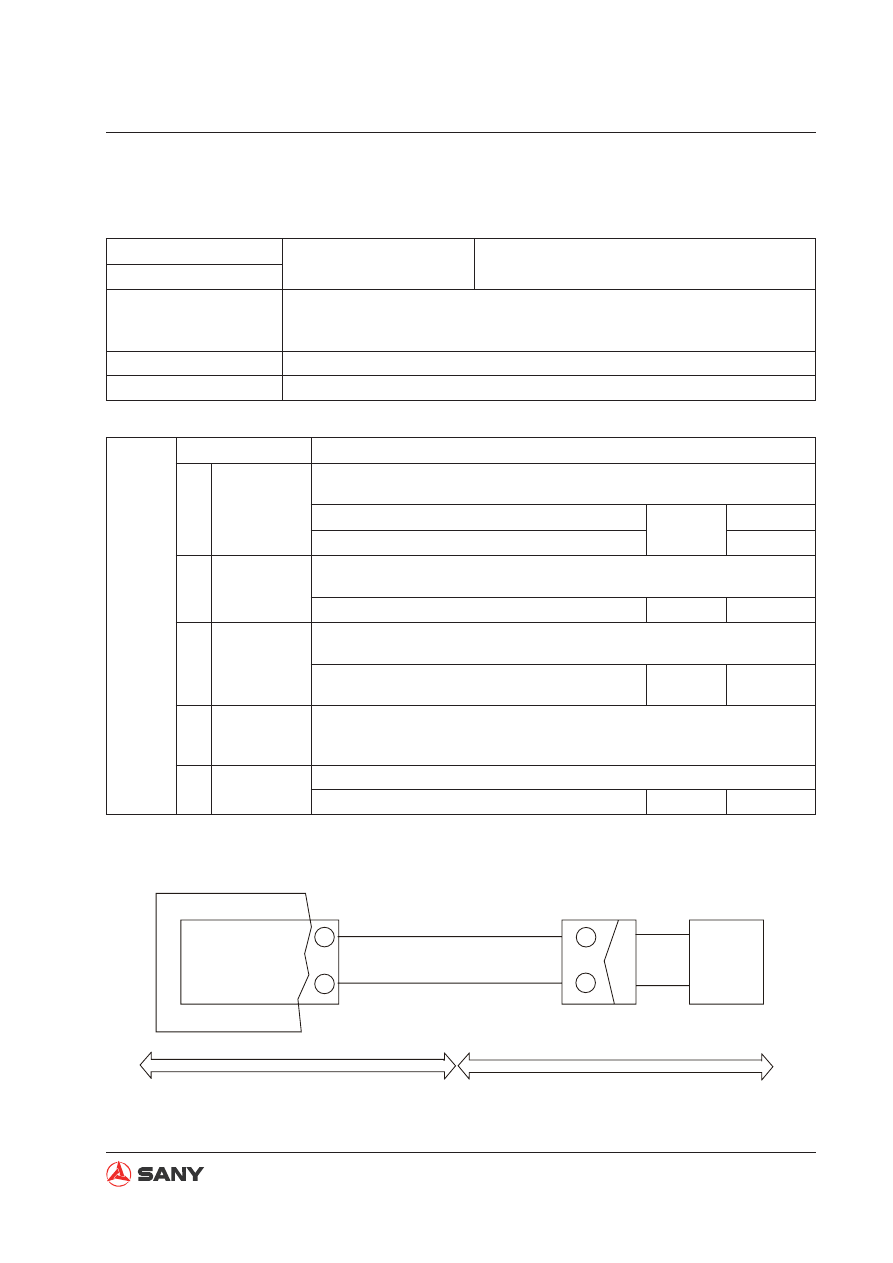
7-43

Troubleshooting

SY365(B)H-9 Crawler Hydraulic Excavator

E435 Rear pump proportional solenoid current abnormal (A)

Failure code

Failure symptom

Rear pump proportional solenoid current is abnor-
mal. The system operates slowly. 

E435

Failure description

Abnormality occurs in loaded circuit of proportional solenoid. Current which is 
above 1.3A lasts for 3 second. Differential current occurs in drive protection 
loop.

Controller reaction

Stop the solenoid when failure is detected. Power supply must be restored. 

Symptom on machine System operates slowly.

Possible causes and standard values

Cause

Standard values and troubleshooting references

1

Open circuit of

harness


Ɣ

Turn engine start switch to the OFF position before troubleshooting. 
Keep it in the OFF position while troubleshooting is performed. 

Between CN-113F 

ķ

 and pin 17 of controller

Resistance

Under 1

ȍ

Between CN-113F 

ĸ

 and ground

Under 1

ȍ

2

Short circuit 

of harness 

(grounded)


Ɣ

Turn engine start switch to the OFF position before troubleshooting. 
Keep it in the OFF position while troubleshooting is performed. 

Between CN-113F 

ķ

 and wire 0#

Resistance Above 1M

ȍ

3

Failure of pro-

portional valve 

coil


Ɣ

Turn engine start switch to the OFF position before troubleshooting. 
Keep it in the OFF position while troubleshooting is performed. 

Unplug the connector CN-113F, and measure the 

resistance between solenoid valve's 

ķ

 and 

ĸ

.

Resistance

17.5

ȍ

4

Failure of con-

troller

No troubleshooting can be done for failure occurs in the inner of controller. 

(Except for the above reasons, the controller must be replaced in case of 

this failure.)   

5

CN-151F

703#

0#

17

3

1

2

ZX225-1105015

Controller

Rear pump SV
signal output port

GND

Rear pump SV

Signal

GND

Operator station

Chassis harness

Fig. 7-29 

7-44

Troubleshooting

SY365(B)H-9 Crawler Hydraulic Excavator

E436 Front pump proportional solenoid current abnormal (B)

Failure code

Failure symptom

Front pump proportional solenoid current is ab-
normal. The system operates slowly. 

E436

Failure description

Abnormality occurs in loaded circuit of proportional solenoid. Current which is 
under 0.2 A lasts for 3 seconds and PWM output is greater than 10V. 

Controller reaction

Stop the solenoid when failure is detected. Power supply must be restored. 

Symptom on machine System operates slowly. 

Possible causes and standard values

Cause

Standard values and troubleshooting references

1

Open circuit of 

harness


Ɣ

Turn engine start switch to the OFF position before troubleshooting. 
Keep it in the OFF position while troubleshooting is performed. 

Between CN-150F 

ķ

 and pin 28 of controller

Resistance

Under 1

ȍ

Between CN-150F 

ĸ

 and ground

Under 1

ȍ

2

Short circuit 

of harness 

(grounded)


Ɣ

Turn engine start switch to the OFF position before troubleshooting. 
Keep it in the OFF position while troubleshooting is performed. 

Between CN-150F 

ķ

 and wire 0#

Resistance Above 1M

ȍ

3

Failure of pro-

portional valve 

coil


Ɣ

Turn engine start switch to the OFF position before troubleshooting. 
Keep it in the OFF position while troubleshooting is performed. 

Unplug the connector CN-150F, and measure 

the resistance between solenoid valve's 

ķ

 and 

ĸ

.

Resistance

17.5

ȍ

4

Failure of con-

troller

No troubleshooting can be done for failure occurs in the inner of controller. 

(Except for the above reasons, the controller must be replaced in case of 

this failure.)   

5

28

3

1

2

CN-150F

702#

0#

ZX225-1105014

Controller

Front pump SV
signal output port

GND

Operator station

Chassis harness

Front pump SV

Signal

GND

Fig. 7-30 

7-45

Troubleshooting

SY365(B)H-9 Crawler Hydraulic Excavator

E437 Rear pump proportional solenoid current abnormal (B)

Fig. 7-31 

Failure code

Failure symptom

Rear pump proportional solenoid current is abnor-
mal. The system operates slowly. 

E437

Failure description

Abnormality occurs in loaded circuit of proportional solenoid. Current which is 
under 0.2 A lasts for 3 seconds and PWM output is greater than 10V. 

Controller reaction

Stop the solenoid when failure is detected. Power supply must be restored. 

Symptom on machine System operates slowly.

Possible causes and standard values

Cause

Standard values and troubleshooting references

1

Open circuit of

harness


Ɣ

Turn engine start switch to the OFF position before troubleshooting. 
Keep it in the OFF position while troubleshooting is performed. 

Between CN-151F 

ķ

 and pin 17of controller

Resistance

Under 1

ȍ

Between CN-151F 

ĸ

 and ground

Under 1

ȍ

2

Short circuit 

of harness 

(grounded)


Ɣ

Turn engine start switch to the OFF position before troubleshooting. 
Keep it in the OFF position while troubleshooting is performed. 

Between CN-151F 

ķ

 and wire 0#

Resistance Above 1M

ȍ

3

Failure of pro-

portional valve 

coil


Ɣ

Turn engine start switch to the OFF position before troubleshooting. 
Keep it in the OFF position while troubleshooting is performed. 

Unplug the connector CN-151F, and measure 

the resistance between solenoid valve's 

ķ

 and 

ĸ

Resistance

17.5

ȍ

4

Failure of con-

troller

No troubleshooting can be done for failure occurs in the inner of controller. 

(Except for the above reasons, the controller must be replaced in case of 

this failure.)   

5

CN-151F

703#

0#

17

3

1

2

ZX225-1105015

Controller

Rear pump SV
signal output port

GND

Rear pump SV

Signal

GND

Operator station

Chassis harness

7-46

Troubleshooting

SY365(B)H-9 Crawler Hydraulic Excavator

E543 Engine speed abnormal

Failure code

Failure symptom

Engine speed is abnormal.  Only alarm output is 
effective.  

E543

Failure description

CPU detects out that engine speed is too low (below 100 rpm).

Controller reaction

Only alarm output is effective. The alarm resets automatically when conditions 
become normal.

Symptom on machine

——

Possible causes and standard values

Cause

Standard values and troubleshooting references

1

Normal condi-

tion

 Code 43 will be displayed on the monitor when the engine start switch is 

turned from the OFF position to the ON position. 

2

Open circuit of

harness


Ɣ

Turn engine start switch to the OFF position before troubleshooting. 
Keep it in the OFF position while troubleshooting is performed. 

Between CN-125M 

ķ

 and pin 16 of controller

Resistance

Under 1

ȍ

Between CN-125M 

ĸ

 and pin 6 of controller

Under 1

ȍ

3

Short circuit 

of harness 

(grounded)


Ɣ

Turn engine start switch to the OFF position before troubleshooting. 
Keep it in the OFF position while troubleshooting is performed. 

Between CN-125M 

ķ

 and ground

Resistance Above 1M

ȍ

4

Failure of sen-

sor


Ɣ

Turn engine start switch to the OFF position before troubleshooting. 
Keep it in the OFF position while troubleshooting is performed. 

Unplug the  connector CN-125M, and measure 

the resistance between 

ķ

 and 

ĸ

 of the speed 

sensor.

Resistance

2.3 0.2

k

r

:

5

16

6

1

2

CN-125M

ZX225-1105017

108A

108B

Controller

Engine speed collection

GND

Engine speed sensor

Signal

GND

Operator station

Chassis harness

Fig. 7-32 

7-47

Troubleshooting

SY365(B)H-9 Crawler Hydraulic Excavator

E244 Fuel control dial setting voltage abnormal 

Failure code

Failure symptom

Fuel control dial setting voltage is abnormal and engine 

returns auto deceleration.

E544

Failure description

When power is on, voltage of fuel control dial other than 0.25-4.75V lasts for over 

200 msec.

Controller reaction

Throttle is moved to idle position.

Symptom on machine

Engine returns auto deceleration. 

25

16

19

3

4

5

3

4

5

3

9

2

3

9

2

CN-7-113M

CN-209F

7

9

8

7

9

8

CN-501F

50#

506#

0#

ZX225-1105018

Sensor 5V

GND

Fuel control dial 
setting voltage

Yellow

Red

Blue

Fuel
control 
dial

Operator station

Possible causes and standard values

Causes

Standard values and troubleshooting references

1

5V power

failure


Ɣ

Turn the start switch to the OFF position before troubleshooting. Keep it in the 
ON position while troubleshooting is performed.

CN-501F 

Ľ

 and 

Ŀ

 Volt

About 5V

2

Open circuit 

of signal 

line


Ɣ

Turn the start switch to the OFF position before troubleshooting. Keep it in the 
OFF position while troubleshooting is performed.

CN-501F 

ľ

 and controller pin19

Resistance

Under 1

ȍ

3

Short cir-

cuit of 

signal line 

(grounded)


Ɣ

Turn the start switch to the OFF position before troubleshooting. Keep it in the 
OFF position while troubleshooting is performed.

CN-501F 

ľ

 and ground

Resistance

Above 2M

ȍ

4

Short circuit 

of signal 

line (con-

tact with 

power sup-

ply)


Ɣ

Turn the start switch to the OFF position before troubleshooting. Keep it in the 
ON position while troubleshooting is performed.

CN-501F 

ľ

 and ground

Volt

Under 5V

5

Dial failure


Ɣ

Turn the start switch to the OFF position before troubleshooting. Keep it in the 
OFF position while troubleshooting is performed.

Unplug connector CN-501F and measure fuel con-

trol dial 

Ľ

 and 

Ŀ

.

Resistance

5K±15%

ȍ

Fig. 7-33 

7-48

Troubleshooting

SY365(B)H-9 Crawler Hydraulic Excavator

E145 CAN bus abnormal

Failure code

Failure symptom

Abnormality of CAN bus activates alarm.

E145

Failure description

Time-out of CAN bus communication lasts for over 3s. 

Controller reaction

Only alarm output is effective.

Symptom on machine

----

Possible causes and standard values

Causes

Standard values and troubleshooting references

1

CAN re-

sistance 

failure


Ɣ

Turn the start switch to the OFF position before troubleshooting. Keep it in the 
OFF position while troubleshooting is performed.

Between CN-7-709 A and B

 Resistance

60

ȍ

Between CN-185 A and B

Resistance

60

ȍ

2

Open circuit

of Harness


Ɣ

Turn the start switch to the OFF position before troubleshooting. Keep it in the 
OFF position while troubleshooting is performed.

Unplug controller connector and measure pin 

12 and CN-7-112 A.

Resistance

Under 1

ȍ

Unplug controller connector and measure pin 

11 and CN-7-112 B.

Under 1

ȍ

3

Control-

ler internal 

failure

No troubleshooting can be done for failure occurs in the inner of controller. (Except 

for the above reasons, the controller must be replaced in case of this failure.)   

CN-185M

CN-221M

A

B

A

B

A

B

CN-7-112F

CN222F

CN-7-113M

CN-7-709M

1

4

7

2
9

CANH

CANH

CANL

CANL

42

43

0

0

35
12

5

24

11

21

20

31

12

11

F11 15A

F13 10A

ZX335-1005040

Controller 

120 ohms

120 ohms

Monitor

Operator station

Chassis harness

PWR

PWR

Fi

7 30

Fig. 7-34 

7-49

Troubleshooting

SY365(B)H-9 Crawler Hydraulic Excavator

7.5  Troubleshooting Electrical System (E-Mode)

E-1  Engine does not crank .......................................................................................... 7-51
E-2  Engine runs rough or is unstable .......................................................................... 7-54
E-3  Power supply of machine cannot be cut off .......................................................... 7-55
E-4  Throttle motor not working .................................................................................... 7-56
E-5  Auto idle not functioning ........................................................................................ 7-57
E-6  Preheat function fails ............................................................................................ 7-59
E-7  All components not working .................................................................................. 7-60
E-8  Boom-up speed or power is low............................................................................ 7-61
E-9  Arm speed or power is low .................................................................................... 7-62
E-10  Bucket speed or power is low ............................................................................. 7-63
E-11  Travel speed or power is low ............................................................................... 7-65
E-12  Blank monitor display .......................................................................................... 7-66
E-13  Monitor displays nothing ..................................................................................... 7-67
E-14  Dual speed travel not functioning........................................................................ 7-68
E-15  Incorrect engine coolant reading......................................................................... 7-69
E-16  Incorrect fuel level reading .................................................................................. 7-70
E-17  Wiper does not work ........................................................................................... 7-71
E-18  Incorrect arm-in pilot pressure reading ............................................................... 7-72
E-19  Incorrect arm-out pilot pressure reading ............................................................. 7-73
E-20  Incorrect boom-up pilot pressure reading ........................................................... 7-74
E-21  Incorrect boom-down pilot pressure reading....................................................... 7-75
E-22  Incorrect bucket-dig pilot pressure reading ......................................................... 7-76
E-23  Incorrect bucket-dump pilot pressure reading..................................................... 7-77
E-24  Incorrect swing pilot pressure reading  ............................................................... 7-78
E-25  Left travel pilot pressure reading incorrect .......................................................... 7-79
E-26  Right travel pilot pressure reading incorrect ....................................................... 7-80

7-50

Troubleshooting

SY365(B)H-9 Crawler Hydraulic Excavator

Fuse box connection table


This table gives all power supply units and rated currents of fuse box power supplies. 


If power supply is normal, check the fuse box and fuses when you perform troubleshooting of 
the electrical system. 

Information contained in troubleshooting table

Failure information 

Symptom on machine

Related information

Failure occurred and troubleshooting information

Possible causes and standard values

Cause

Standard values and troubleshooting referenc-

es

1

Possible causes of trouble 
(Given numbers are refer-
ence numbers, which do not 
indicate priority)

<Inclusion>


Standard value under normal condition can 
be used to judge possible causes


Reference for passing the above "Good" or 
"No Good" judgement

<Symptom of Wiring Harness Failure>


Open circuit

Faulty contact with connector or open cir-
cuit in wiring harness 


Faulty grounding

An ungrounded wiring is grounded. 


Short circuit

A wiring has mistaken contact with a 24 V 
electric circuit. 

7-51

Troubleshooting

SY365(B)H-9 Crawler Hydraulic Excavator

E-1  Engine does not crank

Trouble

Engine cannot be started. 

Related information

Possible causes and standard values

Cause

Standard values and troubleshooting references

1

Low battery
capacity

 Turn engine start switch to the OFF position before troubleshooting. Keep 

it in the OFF position while troubleshooting is performed. 

Battery voltage

Voltage

24V

2

Internal fail-
ure of engine 
start switch

 Turn engine start switch to the OFF position before troubleshooting. Keep 

it in the OFF position while troubleshooting is performed. 

OFF position: between wire 22# and wire 11#  Resistance

1M

Ω

3

Failure of pilot 
switch

 Turn engine start switch to the OFF position before troubleshooting. Keep 

it in the OFF position while troubleshooting is performed. 

Lockout control in unlocked position: between 
105 # and 27# wire

Resistance

1

Ω

Lockout control in locked position: between wire 
105 #  and wire 27# 

1 M 

Ω

4 Failure of 

start motor

  Turn engine start switch to OFF position. Keep the engine running during 

troubleshooting. (When all power supplies, grounding, signal and engine 
inputs are normal except engine output, it is the failure of  start motor)

Engine starting motor

Start switch

Voltage

Power supply: Terminal B and ground

Start

20

30V

Between start motor input terminal S and ground

20

30V

5

Open circuit
of harness

  Turn engine start switch to OFF position before proceeding. Turn it to the 

ON position to perform troubleshooting. 

Wire 21#  and start motor terminal B

Resistance

1

Ω

Wire 12#  and start motor terminal S

1

Ω

Start relay terminal L and safety relay terminal S

1

Ω

7-52

Troubleshooting

SY365(B)H-9 Crawler Hydraulic Excavator

Possible causes and standard values

Cause

Standard values and troubleshooting references

6

Failure of fuse 
F1

Battery terminal "+" (wire 20#) and control dial 
wire 22#

Resistance

1

Ω

7

Short circuit 
of harness 
(grounded)

 Turn engine start switch to the OFF position before troubleshooting. 

Keep it in the OFF position while troubleshooting is performed. 

Start relay terminal S  and ground

Resistance

1 M 

Ω

Start motor input terminal S and ground

1 M 

Ω

8

Internal failure
of alternator

 Turn engine start switch to the OFF position before troubleshooting. Turn  

the start switch to the ON position and keep it in the ON position while 
troubleshooting is performed. 

Alternator terminal R and ground

Voltage

1.5V 

9 Start relay

Turn engine start switch to OFF position. Move it to ON position when 

performing troubleshooting.  
Between relay coils

Resistance

300 

Ω

Between start relay terminal B and line 11#

1

Ω


10

Failure of
parking unit

 Turn engine start switch to the OFF position before troubleshooting. Turn 

the start switch to the ON position and keep it in the ON position while 
troubleshooting is performed. 

Check parking relay

Resistance

Measure resistance of motor coil. 

Approx 63

Ω

7-53

Troubleshooting

SY365(B)H-9 Crawler Hydraulic Excavator

ZX225-1105020

0

0

0

k3

0

k11

0

0

C

R2

S0

BR ACC

B

HEAT

ON

OFF

TERMINAL

R1

START

897044-4180

B2

63

65

64

17

21

0

22

11

60

14

14

0

21

105

20

22

61 11

F1-20A

E3

k7

F13-160A

F2-10A

0

HLR

E2

G

k1

k3

GR-1 GLOW PLUG

B1

BAT-1

+

-

-

+

F7-10A

27

0

606

0

D-10

D-1

15

k-8

22

15a

620

11a

P600G

14

16

60

12

S

E

M1

B

M

B

C

R

E

S

11b

R0

1

2

4

3

66

HL2

2

5

6

69

1

3

4

68

61

13

62

P1

E

P2

A

B

5

1

6

2

3

L

R
B

E

VA7

Start switch

Low-temp switch

Preheat 
relay

PReheat indicator

Preheat controller

Preheater

Charging indicator

Start motor

Engine

Parking motor

Parking relay

Safety relay

Pilot solenoid valve

Lockout relay

Start relay

SQ1 Pilot switch

Shutdown relay

Pilot valve relay

K4

Battery

Battery
relay

Fig. 7-35 

7-54

Troubleshooting

SY365(B)H-9 Crawler Hydraulic Excavator

E-2  Engine runs rough or is unstable

Failure information

Engine Runs Rough or Is Unstable

Related information

Engine speed can be read on the monitor.

Possible causes and standard values

Cause

Standard values and troubleshooting references

1

Open circuit of

harness


Ɣ

Turn engine start switch to the OFF position before troubleshooting. Keep it in 
the OFF position while troubleshooting is performed. 

Unplug the connector controller, and measure 

the resistance between pin 16 and pin 7. 

Resistance

 2.3±0.2 K

ȍ

2

Internal failure

in sensor


Ɣ

Turn engine start switch to the OFF position before troubleshooting. Keep it in 
the OFF position while troubleshooting is performed. 

Between CN-125M A and B


Resistance

 2.3±0.2 K

ȍ

3

Short circuit 

of harness 

(grounded)


Ɣ

Turn engine start switch to the OFF position before troubleshooting. Keep it in 
the OFF position while troubleshooting is performed. 

Between CN-125M A and ground

Resistance

Above 1M

ȍ

4

Internal failure 
of controller

No troubleshooting can be done due to internal failure. (Failure lies in the control-

ler if the reasons above are ruled out)

5

GND

16

HCU_J1

7

B

A

S-2

CN-125M

ZX225-1105021

Controller

RPM sensor

Signal

GND

Chassis harness

Operator station

RPM sensor 
input signal

Fig. 7-36 

7-55

Troubleshooting

SY365(B)H-9 Crawler Hydraulic Excavator

E-3  Power supply of machine cannot be cut off

Failure information

Engine cannot be stopped. 

Related information

Engine stalls when start switch it turned to OFF position. There 
is no time delay for power cutout.

Possible causes and standard 

values

Cause

Standard values and troubleshooting references

1

Failure of battery 

relay

When the engine start switch is operated, if the operation of battery relay con-

tact is heard, the battery is normal. Turn the start switch OFF

ĺ

ON

ĺ

OFF.

2

Breakdown of 

surge diode 


Ɣ

Turn engine start switch to the OFF position before troubleshooting. Keep 
it in the OFF position while troubleshooting is performed. 

Between battery relay wire 20# and  wire 21#

Resistance Above 1M

ȍ

3

ZX225-1105020

0

0

0

k3

0

k11

0

0

C

R2

S0

BR ACC

B

HEAT

ON

OFF

TERMINAL

R1

START

897044-4180

B2

63

65

64

17

21

0

22

11

60

14

14

0

21

105

20

22

61 11

F1-20A

E3

k7

F13-160A

F2-10A

0

HLR

E2

G

k1

k3

GR-1 GLOW PLUG

B1

BAT-1

+

-

-

+

F7-10A

27

0

606

0

D-10

D-1

15

k-8

22

15a

620

11a

P600G

14

16

60

12

S

E

M1

B

M

B

C

R

E

S

11b

R0

1

2

4

3

66

HL2

2

5

6

69

1

3

4

68

61

13

62

P1

E

P2

A

B

5

1

6

2

3

L

R
B

E

VA7

Start switch

Low-temp switch

Preheat 
relay

PReheat indicator

Preheat controller

Preheater

Charging indicator

Start motor

Engine

Parking motor

Parking relay

Safety relay

Pilot solenoid valve

Lockout relay

Start relay

SQ1 Pilot switch

Shutdown relay

Pilot valve relay

K4

Battery

Battery
relay

Fig. 7-37 

7-56

Troubleshooting

SY365(B)H-9 Crawler Hydraulic Excavator

E-4  Throttle motor not working

Failure information

Engine speed does not increase or decrease.

Related information

Turn the fuel control dial but engine speed does not 

change.

Possible causes and standard values

Causes

Standard values and troubleshooting references

1

Preheat 

fuse fail-

ure.


Ɣ

 Turn he start switch to the ON position and keep it in the ON position while trouble-
shooting is performed.

The monitor shows failure code 41. Coolant temperature and oil level are normal.

2

Sensor 

power 

abnormal


Ɣ

 Turn he start switch to the ON position and keep it in the ON position while trouble-
shooting is performed.

Measure the voltage between motor plug, 50# wire 

and ground.

Volt

5.0V

3

Throttle 

motor 

failure

Unplug the connector of the harness between throttle motor and chassis.

Measure the resistance between the blue and red 

wires.

Resistance

8~15

ȍ

Measure the resistance between the yellow and 

green wires.

5k

ȍ

 ± 10%

4

Throttle 

motor 

failure


Ɣ

 Turn he start switch to the ON position and keep it in the ON position while trouble-
shooting is performed.

The monitor shows failure codes 41, 12, 13, 14 and 32. 

7-57

Troubleshooting

SY365(B)H-9 Crawler Hydraulic Excavator

E-5  Auto idle not functioning

Failure information

Auto idle speed do not work

Related information

Engine speed do not decrease wen the mode is auto idle 
speed and grip keeps still in NEUTRAL position

Possible causes and standard values

Cause

Standard values and troubleshooting references

1

Error of boom-

up signal


Ɣ

Turn engine start switch to OFF position. Start the engine and keep it run-
ning to perform troubleshooting. 

Levers in NEUTRAL, pressure signal transmitted

Pressure

       0   KG

Lever in operation, pressure signal transmitted

       0-39 KG

2

Error of boom-

down signal


Ɣ

Turn engine start switch to OFF position. Start the engine and keep it run-
ning to perform troubleshooting. 

Levers in NEUTRAL, pressure signal transmitted

Pressure

0   KG

Lever in operation, pressure signal transmitted

 0-39 KG

3

Error of arm-in

signal


Ɣ

Turn engine start switch to OFF position. Start the engine and keep it run-
ning to perform troubleshooting. 

Levers in NEUTRAL, pressure signal transmitted

Pressure

0   KG

Lever in operation, pressure signal transmitted

0-39 KG

4

Error of arm-out

signal


Ɣ

Turn engine start switch to OFF position. Start the engine and keep it run-
ning to perform troubleshooting. 

Levers in NEUTRAL, pressure signal transmitted

Pressure

0   KG

Lever in operation, pressure signal transmitted

0-39 KG

5

Error of bucket-

dig signal


Ɣ

Turn engine start switch to OFF position. Start the engine and keep it run-
ning to perform troubleshooting. 

Levers in NEUTRAL, pressure signal transmitted

Pressure

0   KG

Lever in operation, pressure signal transmitted

0-39 KG

7-58

Troubleshooting

SY365(B)H-9 Crawler Hydraulic Excavator

Possible causes and standard values

Cause

Standard values and troubleshooting references

6

Error of Bucket-

dump signal


Ɣ

Turn engine start switch to OFF position. Start the engine and keep it 
running to perform troubleshooting. 

Levers in NEUTRAL, pressure signal 

transmitted

Pressure

0   KG

Lever in operation, pressure signal 

transmitted

0-39 KG

7

Error of swing 

signal


Ɣ

Turn engine start switch to OFF position. Start the engine and keep it 
running to perform troubleshooting. 

Levers in NEUTRAL, pressure signal 

transmitted

Pressure

0   KG

Lever in operation, pressure signal 

transmitted

0-39 KG

8

Error of travel 

signal


Ɣ

urn engine start switch to OFF position. Start the engine and keep it 
running to perform troubleshooting. 

Levers in NEUTRAL, pressure signal 

transmitted

Pressure

0   KG

Lever in operation, pressure signal 

transmitted

0-39 KG

9

Error of attach-

ment signal


Ɣ

Turn engine start switch to OFF position. Start the engine and keep it 
running to perform troubleshooting. 

Levers in NEUTRAL, pressure signal 

transmitted

Pressure

0   KG

Lever in operation, pressure signal 

transmitted

0-39 KG

10

Failure of con-

troller

No troubleshooting can be done for it is internal failure. (If it is not caused 

by one of the factors listed above, it should be the failure of controller.)


Content      ..     23      24      25      26     ..