SANY Crawler Hydraulic Excavator SY215CLC (CUMMINS QSB6.7 engine). Shop Manual - page 38
 

  Index      Manuals     SANY Crawler Hydraulic Excavator SY215CLC (CUMMINS QSB6.7 engine). Shop Manual


Search            copyright infringement  


Content      ..     36      37      38      39     ..


SANY Crawler Hydraulic Excavator SY215CLC (CUMMINS QSB6.7 engine). Shop Manual - page 38


Disassembly and Assembly

SY215C

LC

8-116


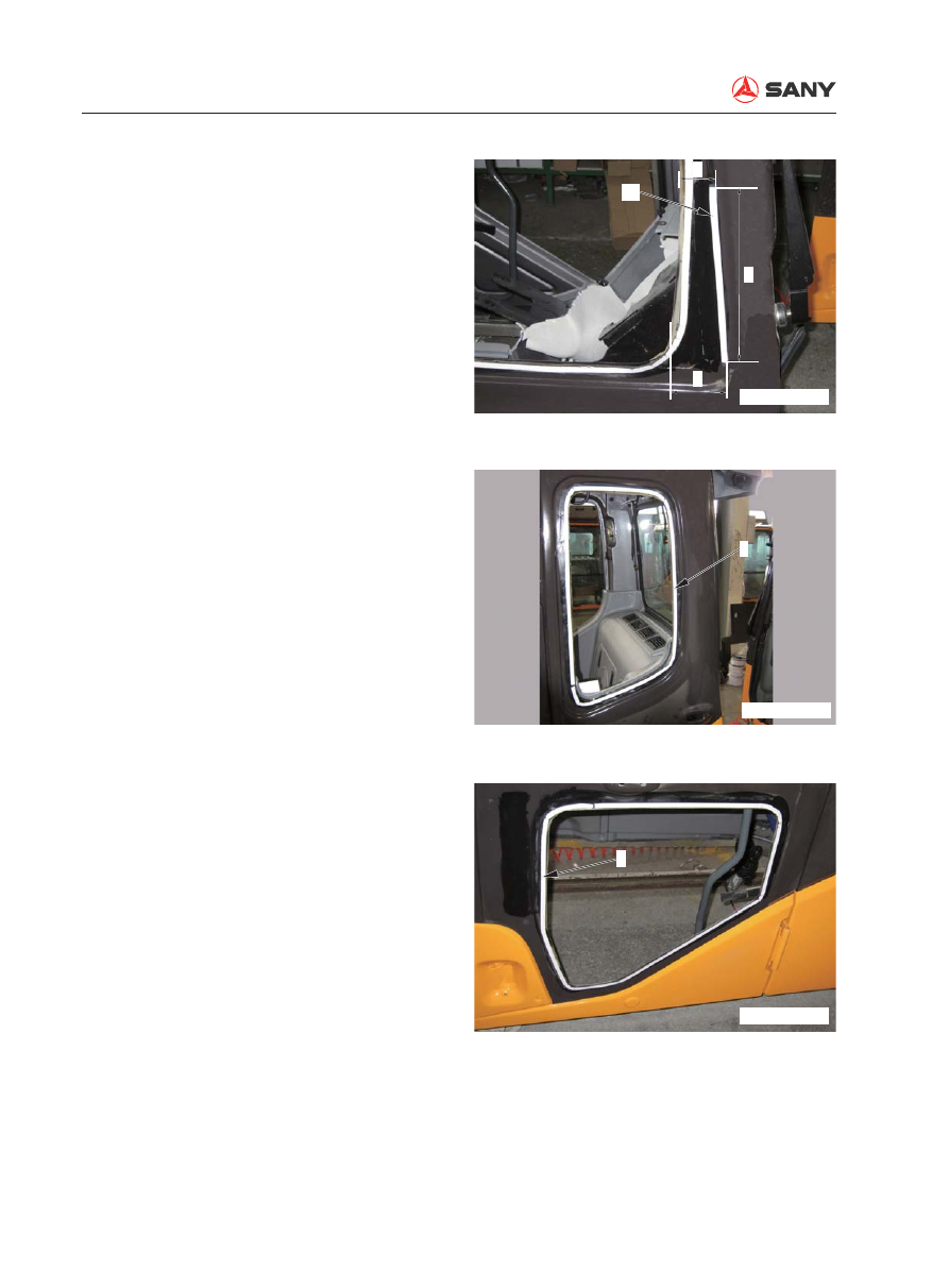
Adhere additional rubber seal (6a) 
onto the right cab window


Position of the additional rubber 
seal: 

(f): 50 mm

(f): 90 mm

(h): 250 mm

2)  Adhere rubber seal (6) on the left cab 

window as illustrated. 

3)  Adhere rubber seal (6) onto the lower 

cab door window as illustrated. 

f

h

g

6a

ZXT225-1006247

6

ZXT225-1006248

6

ZXT225-1006249

Disassembly and Assembly

SY215C

LC

8-117


Adhere additional rubber seal (6b) 
onto the lower cab door window 
frame as illustrated.


Position of additional rubber seal: 

(j): 110 mm

(k): 90 mm

(m): 200 mm

4)  Adhere rubber seal (6) onto the front 

window glass as illustrated. 


Different from the rubber seal (6) on 
other window, rubber seal (6c) on 
the bottom of the front window shall 
be adhered onto the external edge 
of the lower part of the front window 
frame. (If it is adhered along the 
inner edge, the rubber seal will be 
seen through the clear part of the 
glass.)

j

m

k

6b

ZXT225-1006250

6

6c

ZXT225-1006252

6

ZX225-1006251

Disassembly and Assembly

SY215C

LC

8-118

5.  Positioning of new window glass

1)  Check the clearance between the edge 

of glass and the cab in 4 directions, 
and position the glass. Make sure the 
clearance is even.

2)  Put a tape [6] across the glass (9) and 

cab (8) and draw a line (n) on it for 
alignment. 


Adhere tape [6] at 3 points as 
illustrated for precise alignment of 
right window glass, left rear window 
glass and cab door lower window 
glass. 

3)  Cut the tapes across the glass (9) and 

the cab (8) and remove the glass.


Do not remove the tape on the left 
side of the glass until the glass is 
installed. 


When positioning front window 
glass (4), cover it across the width 
of the window frame in the horizon-
tal direction. 

Set the clearance (p) between the 
top edge of the glass and the upper 
frame at 3 mm when positioning it in 
the vertical direction. 

8

9

[6]

n

ZXT225-1006253

[6]

[6]

[6]

8

9

ZX225-1006254

P

4

ZX225-1006255

Disassembly and Assembly

SY215C

LC

8-119

6.  Adhesive


Store adhesion agent in dark places 
where temperature is blow 25°C.


Do not heat the adhesive to above 
30°C.


Before using adhesive that has been 
unsealed, remove the hardened part at 
the nozzle. 

1)  Open the aluminum seal (13) on the 

head of the cylinder (12) and install the 
nozzle.

 Adhesive:

Sunrise MSI SR sealant U90 4463876

2)  Cut the tip of nozzle as illustrated. Di-

mension of the cut: 


(q): 10 mm


(r): 5 mm

3)  Set the cylinder (12) in the gun [7].


An electrical caulking gun is more 
ef

fi

 cient.

13

12

ZX225-1006256

q

r

14

ZX225-1006257

12

[7]

ZX225-1006258

Disassembly and Assembly

SY215C

LC

8-120

4)  Remove the waxed paper of the rubber 

seal on the surface where adhesive is 
to be applied. 

5)  Apply adhesive (15) along the external 

edge of the rubber seal (6).


Adhesive (15) for rubber seal (6) 
on cab (8) shall be applied  as 
illustrated: 


Dimension of (s): 10 mm


Dimension of (t): 15 mm


Adhesive (15) shall be thicker that 
the rubber seal (6).


Apply adhesive of the same thick-
ness evenly. 

6

15

ZX225-1006259

s

8

t

6

15

ZX225-1006260

Disassembly and Assembly

SY215C

LC

8-121


Apply adhesive (15) onto the 
additional rubber seal of the right 
window (6a) and additional rubber 
seal of the cab door lower window 
(6b).

7.  Install window glass

1)  Install window glass (9) and align it with 

the mark on the cab. (See step 5)


Since the glass can not be remove 
once installed, be very careful when 
performing this task.


Install the glass properly within 5 
minutes after adhesive has been 
applied.

2)  Press the perimeter of the glass (9) 

after is has been put in place until it is 
securely stuck to the rubber seal. 


Press the corners of the glass hard.

6a

15

ZX225-1006261

15

6b

ZX225-1006262

9

ZXT225-1006263

Disassembly and Assembly

SY215C

LC

8-122


After the front window glass has 
been installed, fill the clearance  
between the glass on area (s) and 
the center adjusting seal (16) to 
the dimension of (t) and (u). Coat 
primer onto glass (4) on section A-A 
and apply the adhesive as 

fi

 llers.


Dimension of (t): 2 mm


Dimension of (u): 5 mm


Use a rubber spatula to cover the 
edge of the glass and trim the 
adhesive. 


Remove surplus adhesive.

 Glass primer:

Sunrise MSI Primer 35

 Adhesive:

Sunrise MSI SR Sealant U90 

4463876

ZX225-1006264

4

t

A-A

16

u

A

A

S

Disassembly and Assembly

SY215C

LC

8-123

8.  Fix the glass

1)  After the right window glass (1) has 

been adhered to the cab, put position-
ing chips a (1 or 2 pcs) beneath the 
glass in order to 

fi

 x it. 

2)  Use foam polystyrene blocks [9] and 

rubber band [10] to fix the glass and 
the rubber seal as illustrated. 

9.  After the glass has been fixed, remove 

all the remaining primer and adhesive on 
the cab and on the glass.


Clean the adhesive with unleaded 
gasoline before it is hardened. 


Do not apply impacting force onto the 
glass when cleaning it. 

10.  Protection of 

fi

 xed window glass

1)  Remove the positioning chips, foam 

polystyrene blocks and the rubber band 
after 10 hours. 

(Condition: Temperature: 20; humidity: 
60%)

2)  Wait for another 14 hours after the re-

moval of positioning chips, foam poly-
styrene blocks and rubber band before 
operating the machine. 

[9]

[10]

ZX225-1006266

1

a

ZXT225-1006265

Disassembly and Assembly

SY215C

LC

8-124

8.28  Front Window AS - Disassemble and Assemble

 Lower the work equipment onto the 

ground and shut down the engine. 


The front window assembly must be 
removed from the cab in order to replace 
the front window glass. Disassembling 
and assembling method of front window 
assembly (frame and glass) is illustrated in 
the following part.

8.28.1 Disassemble

1.  Raise the front window assembly to the 

roof and secure it with the rear locks (at 
both sides).

2.  Remove left corner plate (1) and right 

corner plate (2).                                    


Mounting bolt (4) and washer (3) of the 
left corner plate will be used in Step 6 
to hang the pull rod.

4

3

1

2

ZX225-1006267

6

5

ZX225-1006268

3.  Release the rear lock of the cab.

4.  Lower the front window assembly care-

fully a bit. Take out and hold the rollers (5) 
and (6) at the bottom of the front window 
from the removed parts in Step 2. 

5.  Remove roller (5) and (6) from both 

sides of the bottom of the front window. 

Disassembly and Assembly

SY215C

LC

8-125

6.    Remove  pin  (7)  at  the  lower  left  side.                           


Plate (8) at the end of the pull rod (9) 
will come out by removing of pin (7).


Hang plate (8) onto the mounting bolt 
of left corner plate (using the washer) 
and 

fi

 x it. 

 A return load of 58.8 N {6 kg}is ap-

plied onto the rear of the cab. Be 
very careful when removing pin (7) 
to disconnect pull rod (9). 

7.  Pull out the front window assembly (10) 

from the opened part of the guide rail and 
lower the assembly gradually. 

6

7

8

9

ZX225-1006269

9

8

ZX225-1006270

10

ZX225-1006271

Disassembly and Assembly

SY215C

LC

8-126

9.  Move the front window assembly (10) 

to the right and the left and remove the 
two upper rollers (11) and (12) from the 
guide rail. Then, remove the front window 
assembly (10).

8.  Lower the front window assembly (10)  

completely. 


Be careful not to allow the front window 
assembly to damage the machine 
monitor. 

10

ZX225-1006272

10

ZX225-1006273

10

12

11

ZX225-1006274

Disassembly and Assembly

SY215C

LC

8-127

8.28.2 Assemble


Reverse the disassembling sequence.


Adjust the opening and closing of the front 
window assembly as per the following in-
struction.

1.  Open and close the front window assembly 

and check if it interferes with the guide rail. 
Check if the roller is jammed. 

2.  If the front window can not be opened or 

closed properly, loosen the mounting bolt 
of the roller adjusting bracket (13) and 
adjust the condition of the front window. 
Tighten the mounting bolt after adjusting. 


Make sure bracket (13) is installed 
without an angle. 

 Mounting bolt: 34.3 N·m {3.5 kgf·m}

13

ZX225-1006275

a

a

2

ZX225-1006276

R

ZX225-1006277

3.  Raise the front window assemble and fix 

it with rear locks (at both sides).


Check if the locks at the rear of the cab 
are securely 

fi

 xed. 

4.  Install the right corner plate (2).


After the "locked" position is adjusted in 
Step 6, tighten the corner plate. 


Install the right corner plate. Clearance 
(a) between the guide rail and the right 
corner plate (2) is 0 – 2.0 mm.


Install the right corner plate. Keep the 
surface (R) of the roller without a level 
error.

Disassembly and Assembly

SY215C

LC

8-128

5.  Install left corner plate (1)


After the "locked" position is adjusted in 
Step 6, tighten the corner plate. 


Install left corner plate. Clearance (b) 
between the guide rail and the left 
corner plate (1) is 0 – 2.0 mm. 


Install left corner plate and keep the 
surface (R) of the roller without a level 
error. (See the previous illustration).

6.  Adjust the "locked" position of the lock of 

front window assembly as per the following 
instruction. 

1)  Tighten the left corner plate (1) and  the 

right corner plate (2) in a nearly correct 
position so that front window glass (14) 
is pressed closely against the adjusting 
seal (19) on the cab. 

b

b

1

ZX225-1006278

15

14

ZX225-1006279

Disassembly and Assembly

SY215C

LC

8-129

2)  Open and close the front window as-

sembly and check the working condi-
tion of left lock (16) and right lock (17). 


If left lock (16) and right lock (17) do 
not work properly, 

i)  Loosen the mounting bolt (19) of 

the lock and move the lock (16) for-
ward. Tighten the bolt after that. 


Adjust the right lock with the same 
method.

ii)  Check again the adaptability be-

tween the front window assembly 
(14) and the adjusting seal (15) on 
the cab. (Checked in Step 1)


Repeat Step i) and Step ii) until the 
condition of front window glass and 
lock (16) and (17) is satisfactory. 
Tighten the mounting bolts of the 
left and right corner plates. 

7.  After adjustment is finished, flush the 

front window glass and check if any water 
leaks into the cab. 

8.  Adjust the "locked" position of the lock of 

front window assembly

1)  After the "locked" position of the lock of 

front window assembly is adjusted in 
Step 6 and Step 7, raise the assembly 
to the roof.

2)  Set the locks of the front window as-

sembly at the rear of the cab at the 
"locked" position, and check the follow-
ing items:


Check the conditions of left lock (16) 
and right lock (17). 


The front window assembly must 
contact the left and right rubber 
stopper (18), and the rubber stop-
pers must be pushed backward by 

17

16

ZX225-1006280

16

19

ZX225-1006281

18

18

ZXT225-1006282

Disassembly and Assembly

SY215C

LC

8-130

3)  Close  the front window assembly (10).

4)  Loosen the retaining nut (20) at the left 

and right side of rubber stopper (18), 
and pull the two rubber stoppers (18) 
inward so that they can not contact the 
"unlocked" front window assembly.

1.5 – 3.0 mm.


The front window assembly shall 
push the limit switch 4 – 7mm back-
ward.

5)  Adjust the position of latch bolt (21).


Latch bolt(21): M10, Inner diameter 
of plate (23): ø14.5 mm

6)  Adjustment of left and right rubber stop-

per (18)

i)  Allow front window assembly (10) 

to contact the left and right rubber 
stopper (18). (when the lock is "un-
locked")

18

20

ZX225-1006283

10

18

ZX225-1006285

23

21

ZXT225-1006284

Disassembly and Assembly

SY215C

LC

8-131

ii)  Lock front window assembly (10).

iii) Turn the left/right rubber stopper 

(18) to the left by one and a half 
round.


Turning the rubber stopper (18) 
leftward for one round is equivalent 
to pressing it by 1.5 mm.


When front window assembly is 
"unlocked", it must move the left/
right rubber stopper (18) by 1.5 – 3.0 
mm.

18

ZX225-1006286

18

20

ZX225-1006287

iv) Tighten the retaining nuts (20) at 

both sides of the rubber stopper 
(18).


Content      ..     36      37      38      39     ..