SANY SRT95C Off-Highway Truck. Service Manual - page 29
 

  Index      Manuals     SANY SRT95C Off-Highway Truck. Service Manual


Search            copyright infringement  


Content      ..     27      28      29      30     ..


SANY SRT95C Off-Highway Truck. Service Manual - page 29


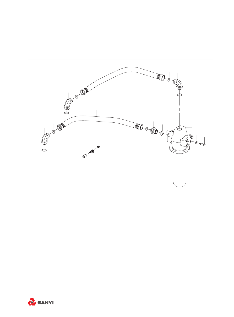
Transmission Oil Filter Assembly

1

1

1

1

2

2

2

3

3

3

3

4

5

6

7

8

9

10

11

12

Fig.1  Transmission Oil Filter Assembly

1. 'O' ring 

7.  Filter assembly

2. Elbow

8.  Adaptor

3. 'O' ring 

9.  Hose assembly 2

4. Hose assembly 1

10. Connector

5. Bolt

11. Adaptor

6. Washer

12. Adaptor

28 TRANSMISSION OIL FILTER ASSEMBLY

Overview

Numbers in parentheses refer to Fig.2.

The transmission oil filter assembly is installed 

on the frame to remove dirt, metals and other 
contaminants  from  the  transmission  oil  to 
reduce wear and provide maximum service life 
for the transmission.
A bypass valve in filter head (1) ensures an 
adequate  flow  of  oil  to  the  transmission  if 
element (2) becomes clogged and cannot pass 
oil through quickly enough to satisfy demand. 
Pressure switch (4, Fig.2) is located in the 
main filter assembly valve block. When the 
filter is blocked to a certain degree, Installed 
in filter head (1) is pressure switch (4) which 
sends a signal to a filter restriction indicator 
warning light (mounted on the dash panel) to 
warn the operator when element (2) becomes 
sufficiently clogged to restrict oil flow. This 
indicates that element (2) should be changed.

Oil flows from the transmission to the inlet side 

of filter head (1) where the oil will then take 
one of two paths:
a. If the oil is cold and thick, or element (2) is 
clogged, oil pressure increases and opens the
bypass valve allowing the oil to bypass the 

filter and flow through filter head (1) and exit at 

the outlet port to the transmission.
b. If the oil is not thick and element (2) is 
not clogged, oil will flow through element (2) 
before returning to the transmission.

Removal

Numbers in parentheses refer to Fig.1, unless

otherwise specified.

WARNING

To prevent personal injury and property 

damage, be sure wheel blocks are properly 

secured and of adequate capacity to do the 

job safely.

1

3

2

4

Fig.2 Main filter assembly

1. Filter head

4. Pressure switch

2. Element

5. Housing

3. 'O' ring 

Transmission Oil Filter Assembly

1. Position the vehicle in a level work area, 
raise the body and secure in place with the 
body safety pins. Apply the parking brake and 
switch off the engine. Turn steering wheel 
in  both  directions  several  times  to  relieve 
pressure in the steering system.
2.  Operate  the  treadle  valve  continuously 
to discharge the brake accumulators. Block 
all road wheels. Set the battery in the ' off ' 
position.
3. Tag filter hose assembly 1 (4) and  hose 
assembly  2  (9)  to  aid  in  installation  and 
disconnect from adaptor (8) and elbow (2) in 

filter assembly (10). remove  'O' ring (3) . Cap 
open line ends and fittings to prevent entry of 

dirt.
4.  Support  filter  assembly  (7)  and  remove 

bolts (5) and washers (6). Then  remove filter 

assembly (7) and drain oil from assembly into 
a suitable container.
5.  If  filter  assembly  (7)  is  being  replaced, 
remove  adaptors (8) and elbow (2) . If filter 
element  (2,  Fig.2)  is  only  being  replaced, 
disassemble filter assembly (7) and replace 
element  (2,  Fig.2)  as  described  under 

changing filter element.
6. If required, remove filter  hose assembly 1 

(4) and  hose assembly 2 (9) from adaptors (2) 
in the transmission. Cap open line ends and 

fittings to prevent entry of dirt.

Installation 

Numbers in parentheses refer to Fig.1, unless

otherwise specified.

1. If new filter assembly (7) is being fitted, 

install adaptors (8) and elbow (2) in filter head 

(1, Fig.2).
2. Position filter assembly (7) to frame and 
secure with bolts (5) and washers (6).
3.  If  filter  hose  assembly  1  (4)  and    hose 
assembly  2  (9)  were  removed,  remove 

blanking caps,  fit  'O' ring (3)  and install lines 

on elbow(2) in the transmission, as tagged 
during removal.

Transmission Oil Filter Assembly

4. Remove blanking caps, fit  'O' ring (3) and 
connect filter hose assembly 1 (4) and  hose 

assembly 2 (9) to adaptor (8) and elbow (2) in 

filter assembly (7), as tagged during removal.

5. Set the battery in the ' on ' position. Start 
the engine and check for leaks.
6. Check transmission oil level and add oil if 
required.
Refer  to  chapter  6,  '  Transmission And 
Mounting ' for correct fill level and Section 
36.1, ' LUBRICATION AND MAINTENANCE ' 

for oil specification.

7. Ensure parking brake is applied, remove the 
body safety pins and lower the body. Remove 
wheel blocks from all road wheels.

Changing filter element

WARNING

To prevent personal injury and property 

damage, be sure wheel blocks are properly 

secured and of adequate capacity to do the 

job safely.

Numbers in parentheses refer to Fig.2, unless

otherwise specified.
Change filter element (2) at intervals specified 

in  Section  36.1,  '  LUBRICATION  AND 
MAINTENANCE '. Element (2) should also be 
changed whenever a transmission overhaul is 
performed, or other internal servicing is carried 
out.
1. Position the vehicle in a level work area, 
raise the body and secure in place with the 
body safety pins. Apply the parking brake and 
switch off the engine. Turn steering wheel 
in  both  directions  several  times  to  relieve 
pressure in the steering system.
2.  Operate  the  treadle  valve  continuously 
to discharge the brake accumulators. Block 
all road wheels. Set the battery in the ' off ' 
position.

Transmission Oil Filter Assembly

3. With a suitable container under the filter 
assembly(7,  fig.1)  to  catch  draining  oil, 
unscrew locking collar on housing (5) and 
remove housing (5) and element (2). Discard 
element (2).

4. Remove and discard 'O' ring (3) from filter 

head (1).
5. Clean housing (5) with clean fuel oil and dry 
with a clean lint free cloth. Lubricate new 'O' 

ring (3) and install on filter head (1).

6. Install new element (2) on filter head (1), 
making sure plastic insert in element centre 

contacts spiral snap ring on filter head (1).

7. Install housing (5) over element (2) and 
secure tightly with locking collar.
8. Set the battery in the ' on ' position. Start 
the engine and check for leaks. Tighten lines, 

fittings and filter locking collar as required.

9. Check transmission oil level and add oil if 
required. Refer to chapter 6, ' Transmission 

And Mounting ' for correct fill level and Section 

36.1, ' LUBRICATION AND MAINTENANCE ' 

for oil specification.

10. Ensure parking brake is applied, remove 
the  body  safety  pins  and  lower  the  body. 
Remove wheel blocks from all road wheels.

Special tools

There  are  no  special  tools  required  for 
procedures outlined in this section. Refer to 
Section 36.3, ' SERVICE TOOLS '.

Transmission Oil Filter Assembly

Disc Brake Cooling System Pipeline And Joint

Overview

The  double-gear  pump  II  installed  to  the 
transmission  PTO  supplies  oil  to  the  disc 
brake cooling system.
The double-gear pump II is a composite gear 
pump assembly consisting of two independent 
parts. The front part includes: driving shaft and 
gear, driven gear and transmission. The rear 
part includes: driving gear, driven gear and 
transmission. The rear part is connected to 
the driving shaft and gear through connecting 
shaft.

Operation

See  Fig.2  for  the  principle  of  double-gear 
pump II.
When the drive gear rotates, the driven gear 
rotates  in  the  reverse  direction. The  tooth 
socket between the teeth of gear will bring the 
hydraulic oil from the gear pump case inlet 
to the outlet.  When the teeth of gears are 
engaged again, the hydraulic is forced out of 
the outlet. The delivery capacity of gear pump 
is determined by the width of its corresponding 
gear set and the rotating speed of drive gear.
The double-gear pump II pumps oil from the 
the tank of hoist and disc brake system and 
send it to the disc brake cooling circuit.

Fig.1 Outline drawing of double-gear pump II 

Fig.2 Outline drawing of double-gear pump II 

29 DISC BRAKE COOLING SYSTEM PIPELINE AND JOINT

Brake Oil Cooler And Installation

Fig.1 Disc brake oil cooler

1. Disc brake oil cooler 

13. Nut

2. Washer

14. Gasket

3. Bolt

15. Washer

4. Sleeve    

16. Bolt

5. Clamp

17. Bolt

6. Coolant outlet pipe

18. Washer

7. Bolt

19. Drain plug

8. Oil Inlet lines

20. Cooler flanges

9. Split flange 

21. Gasket

10. 'O' Ring  

22. Drain plug

11. Oil out lines

23. Heat exchanger

12. Coolant inlet pipe

30 BRAKE OIL COOLER AND INSTALLATION

OIL 

OUTLET 

LINES

11

1

23

20

21

17

18

22

COOLANT 

INLET 

PIPE

12

19

16

15

14

13

7

8

9

10

OIL INLET 

LINES

C

B

D

3

2

4

5

6

COOLANT 

OUTLET 

PIPE

A

Overview and operation

Numbers and letters in parentheses refer to 
Fig.1
The disc brake oil cooler is connected in the 
cooling system between the transmission oil 
cooler and engine oil cooler. The disc brake 
oil cooler is connected in the hydraulic system 
between  disc  brake  filters  and  disc  brake 
assemblies, and is used to cool disc brake 
cooling oil.
The disc brake oil cooler consists mainly of 
heat exchanger (23) and two cooler flanges 
(20),  and  is  mounted  at  the  engine  front 
crossmember.
Coolant enters disc brake oil cooler (1) at 
port  'B'  from  the  engine  water  pump. The 
coolant  circulates  through  cooler  tubes  in 
heat exchanger (23) and exits at port 'A' to 
the transmission oil cooler. Disc brake cooling 
oil enters through ports 'C' from disc brake oil 
filters, circulates around cooler tubes in heat 
exchanger (23) and exits from ports 'D' to rear 
disc brakes.

Note

: Oil flow must always flow in the opposite 

direction to coolant flow through the disc brake 

oil cooler.

Removal

Numbers in parentheses refer to Fig.1.

WARNING

To prevent personal injury and property 

damage, be sure wheel blocks and lifting 

equipment are properly secured and of 

adequate capacity to do the job safely.

1. Position the vehicle in a level work area, 
apply the parking brake and shutdown the 
engine.  Turn  the  steering  wheel  in  both 
directions several times to relieve pressure in 
the steering system. 
2. Block all road wheels, set the switch of 

Brake Oil Cooler And Installation

accumulator into the “off” position.

3. Remove filler cap from the hydraulic oil tank 

to relieve pressure. With a suitable container 
in position, remove drain plug from the bottom 
of the hydraulic oil tank and drain the oil.
4.  Using  a  suitable  lifting  device,  support 
engine  pan  guard  and  remove  mounting 
hardware. Remove engine pan guard from 
truck. Open drain cocks and drain cooling 
system.  Refer  to  Section  32.1  RADIATOR 
AND MOUNTING.
5.  Remove  drain  plugs  (22)  from  the  disc 
brake oil cooler (1) and drain oil into a suitable 
container. Remove bolt (7) and split flange 
(9) securing oil inlet lines (8) to ports 'C', and 
oil outlet line (11) to port ‘D’. Drain oil from oil 
inlet and outlet lines (8 & 11) into a suitable 
container and discard 'O' rings (10). Cap oil 
inlet and outlet lines (8 & 11) and ports 'C',’D’ 
to prevent ingress of dirt.
6.  Remove  drain  plugs  (19)  from  cooler 

flanges (20) and drain coolant into a suitable 

container. Remove clamp (5) securing sleeve 
(4) to ports ‘A’.
7. Support disc brake oil cooler (1) with a 
suitable lifting device and remove bolts (3) 
and  washers  (2)  securing  disc  brake  oil 
cooler (1) to mounting bracket at engine front 
crossmember.  Lower  disc  brake  oil  cooler 
(1)  and  remove  to  a  clean  work  area  for 
disassembly.

Cleaning and Disassembly

Numbers in parentheses refer to Fig.1

Note

:  In  the  event  of  a  major  mechanical 

failure,  transmission  oil  cooler  assembly 
should be cleaned thoroughly or replaced. 
Do not attempt to clean cooler cores, after a 
transmission failure in which metal particles 
from worn or broken parts are released into 
the oil. Replace the cooler cores. 
In  many  areas,  raw  water  is  extremely 
corrosive  or  scale  forming  and  should 
be  treated  to  prevent  damage  to  the  disc 

Brake Oil Cooler And Installation

brake oil cooler (1). A properly maintained 
cooling  system  will  significantly  reduce 
cleaning  intervals.  Refer  to  Section  36.1, 
LUBRICATION AND MAINTENANCE.

Cleaning oil side

WARNING

Dangerous  fumes.  To  prevent  personal 

injury, use trichloroethylene only in the 

open or in a well ventilated room.

1.  Clean  disc  brake  oil  cooler  (1)  before 
sludge hardens. After disc brake oil cooler 
(1) is completely drained, circulate a solution 
of  trichloroethylene  through  the  passages 
surrounding  the  cooler  tubes  in  heat 
exchanger (23) to remove sludge.
2. If cooler tubes are badly clogged, circulate 
an alkaline solution through the heat exchanger 
(23). Solution should be circulated through the 
heat exchanger (23), in the reverse direction 

to normal flow, for approximately 15 minutes, 

after soaking for 10 minutes. The duration of 
circulation depends on how badly clogged the 
cooler tubes are. Flush thoroughly with clean 
hot water.

Cleaning water side

1. Match mark cooler flanges (20) and heat 
exchanger (23) to aid in assembly.
2. Remove washers (18), bolts (17) securing 
cooler flanges (20) to heat exchanger (23). 
Discard gaskets (21).
3.  Make  up  a  solution  composed  of  1/3 
muriatic acid and 2/3 water. To each 9.5 litres 
(2.5 gal) of solution, add 225 g (0.5 lb) of 
oxalic acid.
4.  Immerse  heat  exchanger  (23)  in  the 
cleaning solution. Cleaning action is noticeable 
by bubbling and foaming. The process must 
be  carefully  observed  and  when  bubbling 

Brake Oil Cooler And Installation

stops, usually between 30 - 60 sec, remove 
heat exchanger (23) from cleaning solution 
and flush thoroughly with clean, hot water. 
After cleaning, dip disc brake oil cooler in light 
oil.

Note

: Severely fouled cooler tubes can be 

cleaned by use of a rotary brush if normal 

cleaning is not sufficient.

Assembly

Numbers in parentheses refer to Fig.1.

Note

: Tighten all fasteners without special 

torques specified to standard torques listed in 

Section 36.2, TECHNICAL CONDITIONS FOR 
BOLTS AND NUTS.
1. Install new gaskets (21) to cooler flanges 
(20) and secure cooler flanges (20) to heat 
exchanger (23) with bolts (17), washers (18).
Tighten  bolts  securing  cooler  flanges  (20) 
alternately to give an even seal around cooler 

flange area.

2. Install drain plugs (19 & 22) in underside of 
disc brake oil cooler (1).

Installation 

Numbers and letters in parentheses refer to 
Fig.1

Note:

 Tighten all fasteners without special 

torques specified to standard torques listed in 

Section 36.2, TECHNICAL CONDITIONS FOR 
BOLTS AND NUTS.

WARNING

To prevent personal injury and property 

damage, be sure wheel chocks and lifting 

equipment are properly secured and of 

adequate capacity to do the job safely.

1. Using suitable lifting equipment, position 
disc brake oil cooler (1) to mounting bracket 
at engine front crossmember and secure with 
bolts (3) and washers (2).

Brake Oil Cooler And Installation

2. Install sleeve (4) on coolant outlet pipe (6) 
and secure sleeve (4) to port 'A' with clamps 
(5).
3. Install new gasket (14) on coolant inlet pipe 
(12) and secure coolant inlet pipe (12) to port 
'B' with bolts (16) and nuts (13).
4. Install new 'O' rings (10) on oil inlet lines (8) 
and oil outlet lines (11). Secure oil inlet lines (8) 
to ports 'C' and oil outlet lines (11) to ports 'D' 

with split flanges (9), and bolts (7).

5.  Fill  the  hydraulic  oil  tank  with  hydraulic 
oil specified in Section 36.1, LUBRICATION 
AND MAINTENANCE. Refer to Section 15, 
'HYDRAULIC  OIL  TANK ASSEMBLY'  for 

correct fill level. Install filler cap.

6.  Ensure  all  drain  cocks  on  the  cooling 
system are securely locked and fill cooling 

system with coolant specified in Section 32.1 

'RADIATOR AND MOUNTING'.
7.  Using  suitable  lifting  equipment,  install 
engine pan guard on the truck. Secure engine 
pan guard to the truck with mounting hardware 
removed during removal.
8.  Start  the  engine  and  check  for  leaks. 

Tighten lines and fittings as required.

9. Remove wheel blocks from all road wheels.

Special tools

There  are  no  special  tools  required  for 
procedures outlined in this section. Refer to 
Section  36.3,  MAINTENANCE TOOLS,  for 
part numbers of general service tools required.

Brake Oil Cooler And Installation

Transmission Cooling Piping Mounting

Fig.1 Transmission cooling piping mounting

1.Bolt

18.Bolt

2.Washer

19.Oil outlet pipe assembly

3.Washer

20.Steel tube assembly

4.Nut

21.Fixed plate

5.' O 'ring

22.Washer

6.Flange

23.Nut

7.Washer

24.Fixed plate

8.Bolt

25.Rubber pad

9.Oil inlet pipe assembly

26.Steel tube assembly

10.Clamp

27.Bolt

11.Rubber pad

28.Lockwasher

12.Rubber pad

29.Bolt

13.Steel tube assembly

30.Hose silicone

14.Clamp

31.Oil cooler

15.Hose silicone

32.Gasket

16.Gasket

33.Water inlet tube assembly

17.Water outlet tube assembly

34.Oil outlet pipe assembly

12

11

9

10

1 2 3

4

5

6 7 8

10

10

5

6

7

8

13

14

15

16

17

7

18

8

7

5

19

6

20

21

8

22

22

7

23

5

6

7

8

23

7

22

22

8

24

26

5

28

27

27 28

5

3

2

29

14 30 14

18

7

32

31

33

8

7

6

5

8 7 6

5

34

10

10

14

25

31 TRANSMISSION COOLING PIPING MOUNTING

Overview

Numbers in parentheses refer to Fig.1.
The  transmission  oil  cooler  is  connected 
between  the  radiator  and  transmission  to 
maintain transmission oil within its required 
operating temperature range. Coolant enters 
port ' D ' from disc brake oil cooler, circulates 
through cores in transmission oil cooler (31), 
and exits at port ' A ' to the engine water pump. 
Oil  to  be  cooled  enters  port  '  B  '  from  the 
transmission convertor outlet port, circulates 
around cores in transmission oil cooler (31), 
and  exits  at  port  '  C  '  to  the  transmission 
convertor inlet port.

Note

: Oil flow must always flow in the opposite 

direction to coolant flow through transmission 

oil cooler.

Removal

WARNING

To prevent personal injury and property 

damage, be sure wheel blocks and lifting 

equipment are properly secured and of 

adequate capacity to do the job safely.

1. Position the vehicle in a level work area, 
apply the parking brake and switch off the 
engine.  Turn  the  steering  wheel  in  both 
directions several times to relieve pressure in 
the steering system.
2. Block all road wheels. Set the battery in the 
' off ' position.
3. Open drain cocks and drain the cooling 
system. Refer to chapter 32, ' RADIATOR AND 
MOUNTING ', for procedure.
4. Remove drain plugs from oil cooler (31) and 
drain transmission oil into a suitable container.
5. Remove bolts (8), washers (7) , flange(6) 
and  '  O  '  ring  (5)  securing  oil  inlet  pipe 
assembly (9) to ports 'B' of oil cooler (31).
6.  Drain  oil  into  a  suitable  container.  Cap 

Transmission Cooling Piping Mounting

oil inlet pipe assembly (9)  and port ' B ' to 
prevent ingress of dirt.
7. Remove the oil outlet pipe assembly (34) 
from oil cooler (31) in same method as step 5. 
Cap oil outlet pipe assembly (34)  and port ' C 
' to prevent ingress of dirt.
8.  Slacken clamps (14), drain coolant into 
a  suitable  container.  Remove  bolts  (18)  , 
washers (7) and gasket (32)securing water 
inlet tube assembly (33) to port ' D '.  Cap 
water inlet tube assembly (33)  and port ' D ' to 
prevent ingress of dirt.
9.  Slacken clamps (14), drain coolant into 
a  suitable  container.  Remove  bolts  (18)  , 
washers (7) and gasket (16) securing water 
outlet tube assembly (17) to port ' A '.  Cap 
water outlet tube assembly (17)  and port ' A ' 
to prevent ingress of dirt.
10. Support transmission oil cooler (31) with 
a suitable lifting device and remove nut (4) 
,  bolts  (1,29)  and  washers  (9,10).  Lower 
transmission oil cooler (31) and remove to a 
clean work area.

Cleaning and inspection

Numbers in parentheses refer to Fig.1.

Note

:  In  the  event  of  a  major  mechanical 

failure, transmission oil cooler (31)  should 
be  cleaned  thoroughly  or  replaced.  Do 
not  attempt  to  clean  cooler  cores,  after  a 
transmission failure in which metal particles 
from worn or broken parts are released into 
the oil. Replace the cooler cores. In many 
areas,  raw  water  is  extremely  corrosive 
or  scale  forming  and  should  be  treated  to 
prevent damage to transmission oil cooler 
(31). A properly maintained cooling system will 

significantly reduce cleaning intervals. Refer to 

chapter 32, ' RADIATOR AND MOUNTING ', 
for procedure.

Transmission Cooling Piping Mounting

Clean oil side

WARNING

Dangerous  fumes.  To  prevent  personal 

injury, use trichloroethylene only in the 

open or in a well ventilated room. Avoid 

direct contact with eyes or skin as irritation 

can occur.

1.  Clean  oil  cooler  (31)  before  hardening 
deposits, the oil passages in oil cooler (31) 
by circulating a solution of trichloroethylene 
through the passages, remove all deposits.
2.If the passages are badly clogged, circulate 
an alkaline solution through the oil cooler (31).
After 10 minutes, circulate reversely for 15 
minutes. Flush thoroughly with hot water.

Clean water side

1. Solution is made as follows: add 227 g (0.5 
lb) of oxalic acid to each 9.5 litres (2.5 gal) of 
solution composed of 1/3 muriatic acid and 2/3 
water.
2. Clean the oil cooler (31) by immersing in 
the solution, cleaning action is noticeable by 
bubbling and foaming. The process must be 
carefully observed and when bubbling stops, 
usually  between  30  -  60  seconds,  remove 
oil  cooler  (31)  from  cleaning  solution  and 
flush thoroughly with clean, hot water. After 
cleaning, dip oil cooler (31) in light oil. 

Caution

: If the ordinary cleaning mode is not 

effective, use the rotary brush to remove the 
excessive deposits.

Assembly

Numbers in parentheses refer to Fig.1.

1. Install new gasket  on oil cooler flange and
position oil cooler flange onto oil cooler (31). 

Tighten the bolt.
2.Install the drain plugs onto oil cooler (31).

Transmission Cooling Piping Mounting


Content      ..     27      28      29      30     ..