Shantui SE210 Hydraulic Excavator. Operation & Maintenance Manual - page 4
water immediately.
If the battery electrolyte gets into the eyes, flush immediately with a mount of water,
examined by a doctor as soon as possible.
Check the electrolyte level (except maintenance-free batteries)
1. Open the mechanical right side of the battery box cover.
2. Loosen the cap.
The battery electrolyte level should be above board about 10 mm.
If the level is too low
1. To be filling distilled water.
2. After the filling, operate machine, so that water and electrolyte battery mix,
this is especially important in cold climates.
3. Check the cables and pole terminals are clean, well-fastened, and whether
coated with Vaseline or similar material
Provisions of the battery
Refer to the 62 "battery".
Battery charging
Refer to 64 battery charging.
Alternator
Check the belt tension force
WARNING!
When check the belt tension force, the engine must be stopped,
because the moving parts can cause injury
At the right edge of the belt tension, the belt should be possible to pressure down
about 15 mm. If more than 15 mm, a new belt should be replaced.
Note:Incorrect wiring will affect the alternator’s work and damage the machine,
it should always observe the following instructions
·when the engine is running, the battery and alternator cables can not be disconnected.
Otherwise, the alternator and electronic components may be faulty.
·Before any work is to be done to the alternator, disconnect the battery cables
and insulation
Connect the battery
-Battery terminals must not be confused with each other. (+) or (-) sign are clearly
to be marked on each terminal. If the cable is connected correctly, resulting in the
cable error, alternator rectifier will be damaged immediately.
-When you disconnect the battery, first switch off the circuit with the battery.
Electric welding
-before weld the machine or any mechanical device Installed in the machine,
battery switch must be turned off.
-In any welding machine, you must disconnect the battery cable and plug the cable
plug from the electronic control device.
-when it is open and re-connected, the wire should be no current (off the battery
switch).
-Grounding conductors of welding equipment should be close to the welding point
as soon as possible.
-before welding, remove weld around at least a radius of 10 cm (4 inches) all
paint .because the heat will release harmful gases to paint.
-All paint will break down and format a large number of compounds in the heating
and if prolonged exposure to them, may cause pain, allergy which is Hazardous to
health.
-In addition to health hazards, the welding quality and intensity can be damaged
and even lead to weld fracture in future. So do not the weld on the paint surface
directly.
Storage Box
Summarize
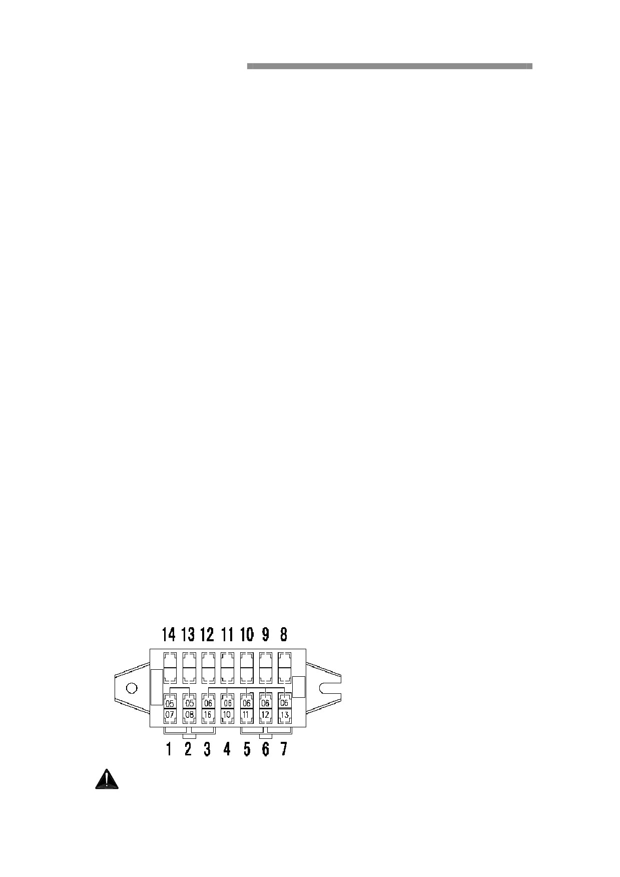
Machine equipped with a fuse box Installed in the bottom of the right control box in
the cab. Fuse box also contains a spare fuse.
WARNING!
Do not install a fuse more than the label of state (a circuit board to
damage or fire hazard).
If the same location of the fuse blows repeatedly, you must find out
the cause of the failure.
Fuses protect electrical equipment from burn out.
If the fuse is eroded or loosened, check and clear the relevant circuit
problems immediately. Replace the fuse if it is broken.
Notice:Only the same fuse as original ones can be used.
Switch off the general switch when replacing the fuse.
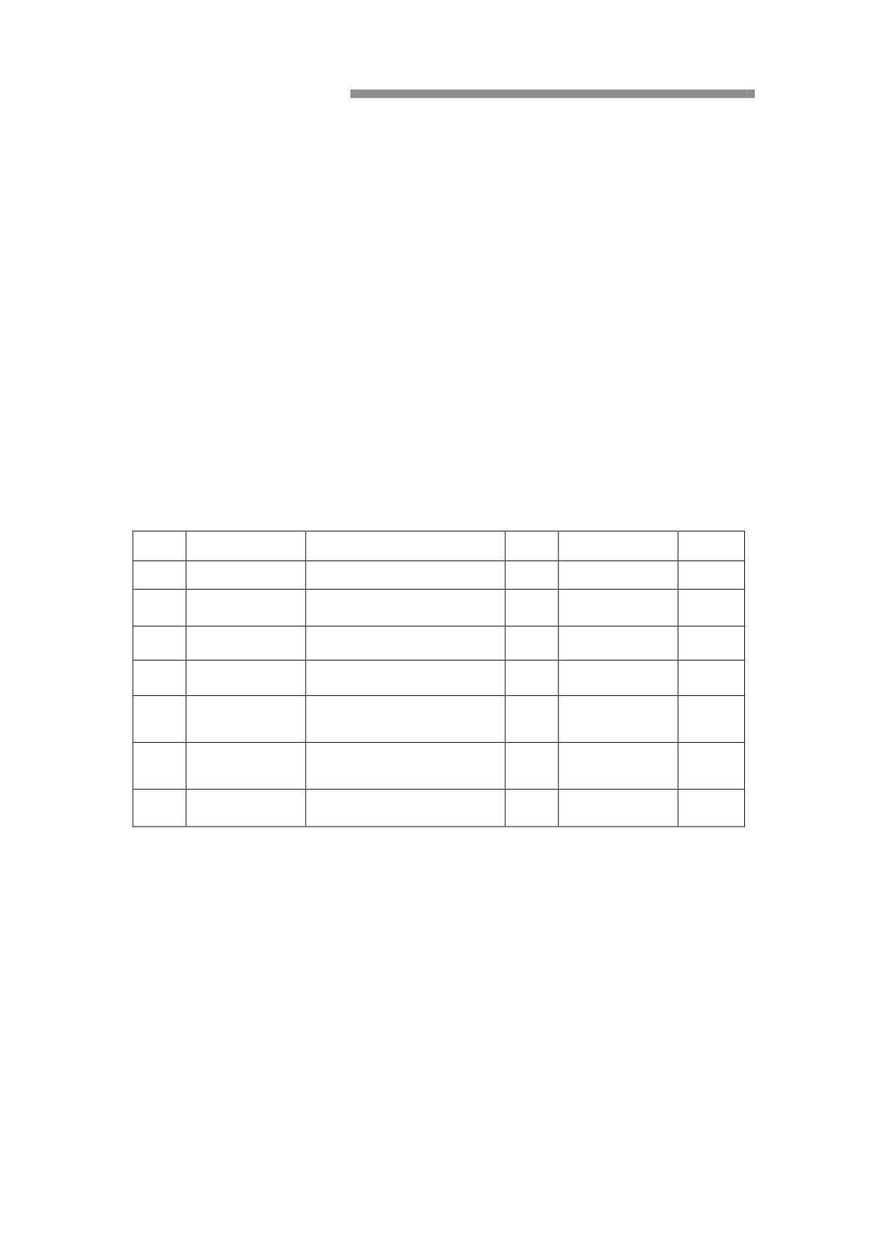
The equipment and circuit of the fuse
NO.
Specification
Circuit
NO.
Specification
Circuit
1
15A
Power electric lock
8
5A
Spare
2
5A
Radio, light lock
9
5A
Spare
3
10A
Electromagnetic valve
10
10A
Spare
4
5A
Relay
11
10A
Spare
air conditioner, Wind
5
10A
12
10A
Spare
device
Speaker, Safety Lock,
6
15A
13
15A
Spare
Light
7
5A
Radio
14
15A
Spare
Hydraulic system
Important!
Keep clean when filling hydraulic oil and operating
hydraulic components.
Check the hydraulic oil level.
Check hydraulic oil level every day.
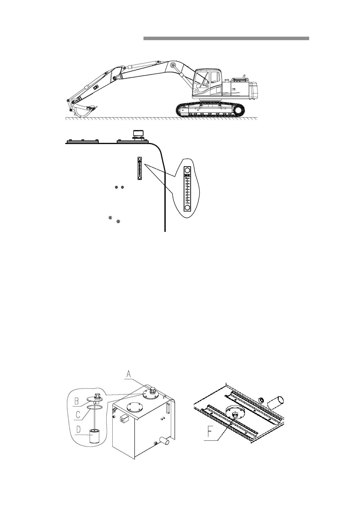
1. Extend the bucket cylinder fully and fully retract stick cylinder, and decline
the work unit to the ground, as shown in photo 80;
2. Stop the engine;
3. Put down safety lock lever and moves left and right joystick in all directions
several times to remove residual hydraulic pressure;
4. Lift safety locking handle , refer to the 25 safety lock system;
5. Turn on right side of the door at upper structure, and check the hydraulic oil
level by visual form, as shown above;
6. If the oil level is in the center of the hydraulic design it is normal. If the oil
level is low, you must fill hydraulic oil.
Replacement of hydraulic oil
Hydraulic oil should be replaced every 2000 hours
WARNING!
Be careful when replacing hydraulic oil, high-temperature will burn
unprotected skin.
1.Turn the upper structure, so that the drain plug which is at the bottom of the
hydraulic oil tank is located between the left and right track;
1. Retract the bucket cylinder fully, recover the arm cylinder fully, and decline
the work unit to the ground. Such as 80 shown in photo;
2. Stop the engine;
3. Put down safety lock lever and moves left and right joystick in all directions
several times to remove residual hydraulic pressure;
4. Lift safety locking handle , refer to the 25 safety lock system;
5. Release internal pressure of the tank by breathing valve (A) , (there are
protective cover installed on the upper, need to be removed first);
6. Unscrew the cover (B);
7. Remove O-ring (C) and coarse filter(D
;
8. Place a container below drain plug(F);
9. Spin open oil drain plug(F
;
10.Discharge hydraulic oil;
11.Tighten the oil drain plug (F);
12.cleaning coarse filter (D) Thoroughly, and re-installation;
13.Perfusion fluid, re-install the cover;
14.Check the oil level on the gauge;
15.when replacing the, total capacity of hydraulic system is about
420
liters ,hydraulic oil tank capacity is about 250 liters.
On the oil level, refer to the 99 recommended lubricant.
Biodegradable hydraulic oil
If you need to replace mineral oils to biodegradable hydraulic oil, please contact the
authorized service center.
Replacement of hydraulic oil return filter
After 250 hours the oil filter should be replaced at the first time, replaced every 1000
hours later.
WARNING!
Before removing the cover (A), the pressure inside the tank must be
released.
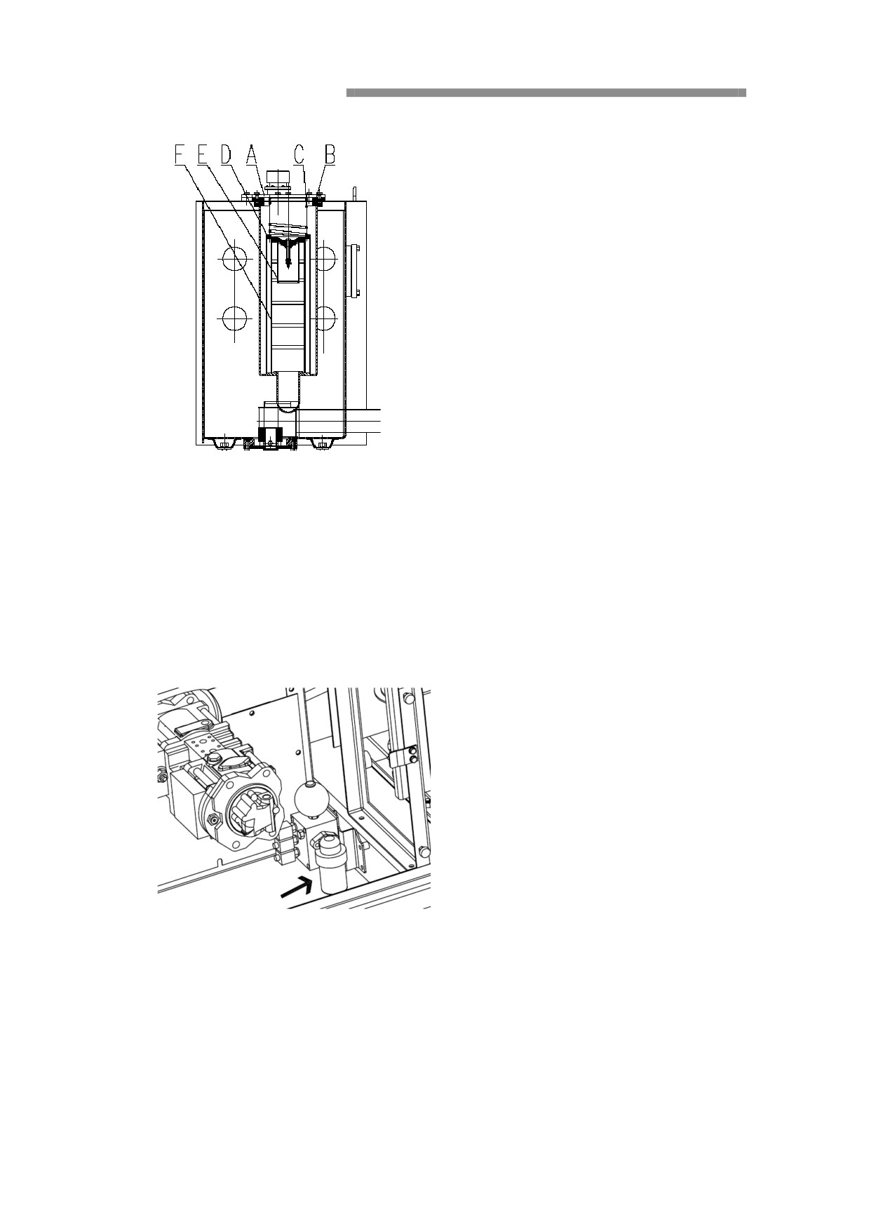
1. Unscrew the lid (A) (there is a protective cover installed on the upper, need to
be removed first);
2. Remove O-ring (B), spring (C) and bypass valve (D), then pull out the filter
bypass valve (E) and the oil filter (F).
3. Clean the removed parts and filter bypass valve (E).
4. Install the new oil return filter (F) and all parts.
5. Start the engine and keep running at low speed for 10 minutes in order to
remove air.
6. Stop the engine
Replacement of Pilot filter cartridge
Replace auxiliary filter element after 250 hours at the first time, replace every
1000 hours later.
1. Place a container below the filter.
2. Remove the filter body.
3. Replace pilot filter cartridge
Cleaning oil filter
Clean coarse filter every 2000 hours, if necessary, then it is replaced.
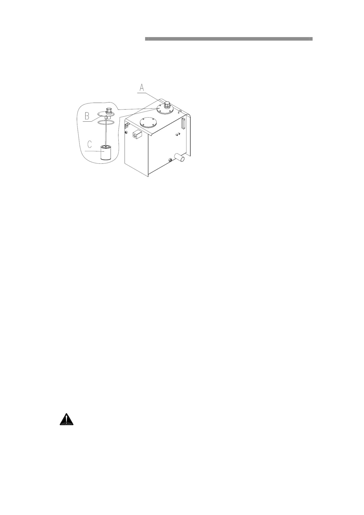
1. Loosen the breathing valve (A) to release the pressure inside the tank out.
2. Unscrew the cover (B), pull out the oil filter (C).
3. Cleaning or replace oil filter according to the number of hours of work.
Replace the air ventilation device components on hydraulic tank
If necessary, replace breathing valve (A) every 2000 hours. When working in dusty
environments for some time, breathing valve will be blocked.
1. Remove the breathing valve.
2. Clean or replace the breathing valve thoroughly.
Rotary drive
Summarize
Important!
Before check the oil level, it is necessary to clean the oil level gauge around. If
there are impurities in the oil, it will damage the rotary drive box.
Maintain oil level normal, check the oil level at operating temperature, it is very
important. Therefore, to keep in mind:
-If the oil is too little, rotary drive impaired because of insufficient lubrication.
-If the oil is too much, it will result in a rotary drive box overheating.
WARNING!Machine just stop working, the oil is hot, be cool
oil.
Check the rotary drive box oil level
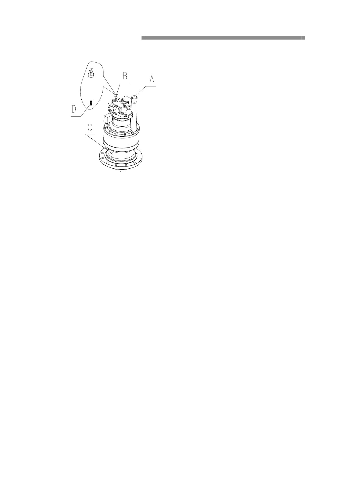
Check the oil level every 250 hours
1. Pull out the oil-foot (B), dry it with a clean cloth.
2. Then insert the oil level scale (B).
3. Then pull out the oil feet (B), and check the oil level. If the oil level in the
center of D, then the oil level is normal.
If the oil level is below the normal oil level, fill the oil through the ventilation port (A)
to the correct oil level. Lubricant specifications: See the 99 recommended lubricant. "
If the oil level is above the correct oil level, loose oil drain plug (C), discharge the oil
to adjust the oil level to the correct oil level. Then tighten the oil drain plug (C).
Replacement of rotary drive box oil
Replace after 500 hours at the first time, replace every 1000 hours later.
1. Prepare a container (10 liters) to emission the filled oil.
2. Put the container below the drain plug, then emission the oil.
3. Open oil drain plug (C), discharge oil.
4. Close the oil drain plug (C).
5. Pull out the oil level-foot (B), fill the oil to the correct oil level through the
ventilation port (A).
6. Then check the oil level, if required, plus note.
Lubricant specifications: See the 99 recommended lubricant.
Track drive
Summarize
Before check the oil level, we should clean up the oil level gauge around. If there are
impurities in the oil, it will damage the track drive boxes.
Maintain oil level normal, and check the oil level at the operating temperature, it is
very important.
Therefore, to keep in mind:
-If too little, drive box does not track drive, will be undermined.
-If the oil is too much, it will from the foam, which will result in track drive boxes
overheating.
WARNING!
Mechanical vehicles just stop working, the oil is hot, be cool oil, the
remaining drive tank pressure may lead to oil or plug injection. So
release the plug slowly.
Check the track drive box oil level
Check the oil level every 250 hours
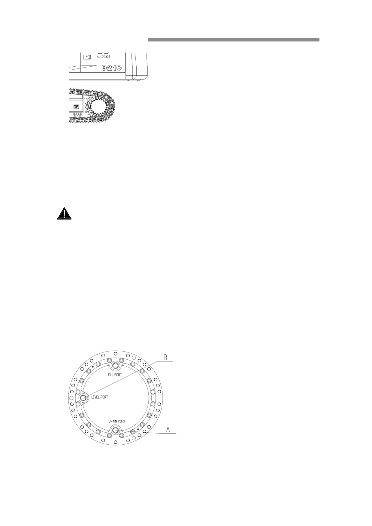
1. Transfer the oil level plug (B) above, so that the drain plug (A) is
perpendicular
to the ground, as the photo shown.
2. Emove the oil level check plug (B). If the oil spill almost from the hole, indicating
the oil level is normal.
If the fuel is short, add the fuel though the injected port (B) to the proper oil level.
Lubrication specification, refer to the 99 recommended lubricant.
Replace track drive tank oil
Replace after 500 hours at the first time, replace every 2000 hours later.
1. Prepare a container (5 liters), then emissions filled oil.
2. Transfer the oil level plug
(B) above, so that the drain plug
(A) is
perpendicular to the ground, as shown above.
3. Put the container (A) below the drain plug.
4. Remove the drain plug (A), oil level check plug (B), and then put the oil.
5. Check the O-ring stuffed, if damaged, must be promptly replaced.
6. Install the drain plug (A)
7. Add oil to the proper oil level from the injection port (C).
Lubrication specification, refer to the 99 recommended lubricant.
8. Install the oil level check plug (B)
Accumulator operation
WARNING!
High pressure nitrogen gas filled accumulator pressure.
To prevent serious casualties, to be careful and follow these
instructions:
Can not tap on the accumulator, drilling or welding.
Away from open flame or other high temperature heat source.
Before disposal, please authorize authorized service center for
pressure relief of the accumulator.
If the engine stopped, operate control handle, the accumulator can
make the device work with their weight down.
After working device down, lift safety lock handle, refer to the 25 safety
lock system
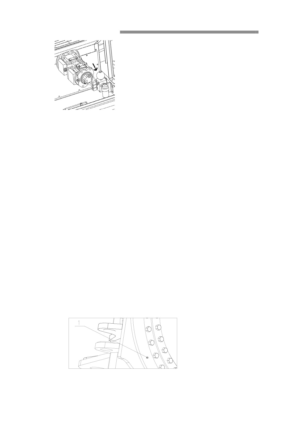
Accumulator operation (emergency)
1. Key to the stop position, stop the engine;
2. Turn the key to running position;
3. Use accumulator operation to make attachment down with their weigh.
Release the pressure of accumulator
1. Make the attachment completely down to the ground;
2. After engine stopped, turn the starter key to connecting position;
3. Put security lock handle down.
4. For the release of the pressure control loop, moving the control handle and
pedal to the Forward / backward, left / right to each location.
5. Turn the starter key to the stop positing.
6. Lift the safety lock handle, refer to the 25 safety lock system
7. Release the hose union slowly, avoid the injection direction of the
hydraulic oil.
Fulling and changing the lubricant
Lubricate the swing circle
Fulling the lubricant every 250 hours
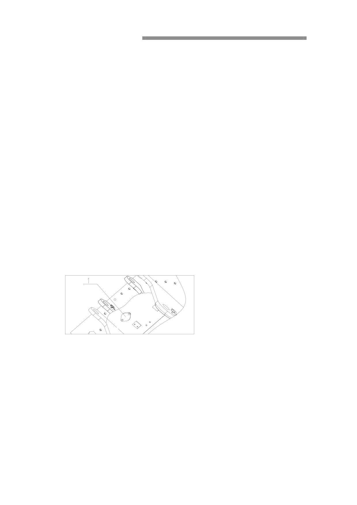
1.
Park the Excavator on level ground.
2.
Put the bucket on the ground
3.
Turn the key start to to “off”
4.
Lift the safety lock lever, refer to the 25 security locking system
5.
Inject the lubricant by the outer oil cup of the swing circle(1)
6.
Start the engine, elevated to the bucket a few inches off the
ground, then rotate the upper structure to the next filling mouth.
7.
Put the bucket on the ground
8.
Starting from step 3, repeat the steps
9.
Injection of grease to the swing circle until the grease overflow from the
joint strip joint of the swing circle.
10. Be careful, don′t add too much
11. After injection of grease, clean the overflow grease.
Check the grease of the swing slot
1. Park the Excavator on level ground.
2. Put the bucket on the ground
3. Turn the key start to to “off”
Lift the safety lock lever, refer to the 25 security locking system
4. Remove cover and bolts (1).
5. Check the oil level and condition of the grease.
6. If necessary, add the grease.
7. Check the pad, replace it if damaged
8. Install the cover.
9. Replace the grease, if the grease is polluted or discoloration
cased by the water. The grease perfusion is about 24 L.
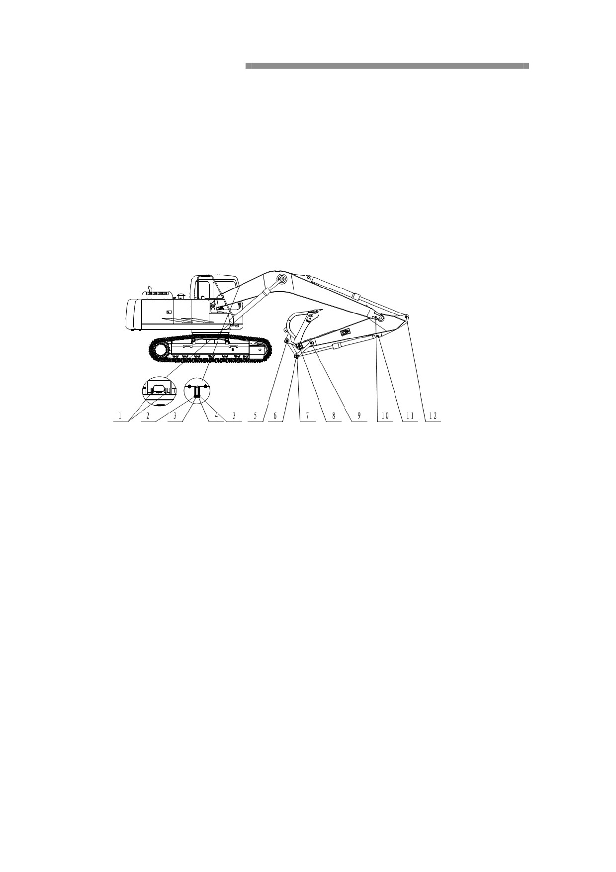
Lubricant the working device
1st using within 50 hours, Maintenance the new machine every 10 working hours or
everyday .
1st using within 100 hours,Maintenance the link system of the working device every
50 working hours or every week.
Notice:
If the machine is used under hard conditions (after using the hydraulic hammer),
embedded in mud, water or abrasive may enter the bearing, maintenance the
link system of the working device every 10 working hours or everyday.
When manual filling the grease, put the working devices on the ground as shown
above chart, and turn off the engine.
Manually or use electric grease gun, full the grease through the grease filling hole.
After fulling the grease, please clean the overflow of grease.
After working in the water, full the new grease to the components (for example pin of
buckets) which are immersed in the water, no matter how the grease filling cycle.
Lubricant specification:refer 98 recommended lubricant.
1.
Boom cylinder install pin(2 points)
2.
The back of boom install pin(2 points)
3.
The end of boom cylinder piston rod pin(2 points)
4.
Arm cylinder install pin(1point)
5.
The connecting pin of connecting rod and bucket(1point)
6.
connecting rod and connecting rod pin(2points)
7.
The end of bucket cylinder piston rod pin(1point)
8.
The connecting pin of arm and bucket(1point)
9.
The connecting pin of arm and connecting rod(1point)
10.
The connecting pin of the front of arm and arm(1point)
11.
Buck cylinder pin(1point)
12.
The concecting pin of arm and piston rod(1point)
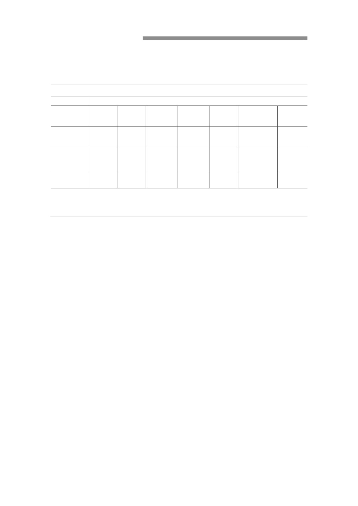
Remmended lubricant and auxiliary materials
Table of Recommended Accessories for SE210 Excavator
Location
Swing
Undercarriage
Hydraulic
Antifreeze
Air
Engine
Fuel
reduction
reduction gear
oil
solution
conditioner
gear unit
unit
API CH-4/
Sulfur
Accessory
API GL-4
API GL-4
SJ SAE
content
ISO VG46
-45℃
R134a
requirement
SAE 90
SAE 85W-90
15W-40
<0.5%
Special
Special
Recommended
Premium
-10# or
hydraulic oil
antifreeze
Mobil GX
Mobil GX
-
variety
Blue
-35#
for
for
SHANTUI.
SHANTUI..
Capacity:
Capacity:25
Amount
20L
360 L
4.4L
2×5.4 L
0.9Kg
360L
L
Description:
The various types of accessories selected in the table are generally required at delivery. For cold northern and hot southern areas,
you can adjust the recommendations in accordance with the requirements of the Owner’s Manual depending on climate
conditions.
Air Conditioning
Important!
Air-conditioning system contains pressurized R134a refrigerant.
According to the provisions of law, don ′t release the R134a refrigerant.
Repair and filling refrigeration systems only by trained personnel, should be
authorized to contact the authorized service center.
Clean or replace the Air-conditioning filters every 1,000 hours or 6 months.
The power of air flow will be reduced, and the capacity of cooling and heating will
be reduced if the air filter is clogged. So it needs to be cleaned regularly
Install and removel the filter:
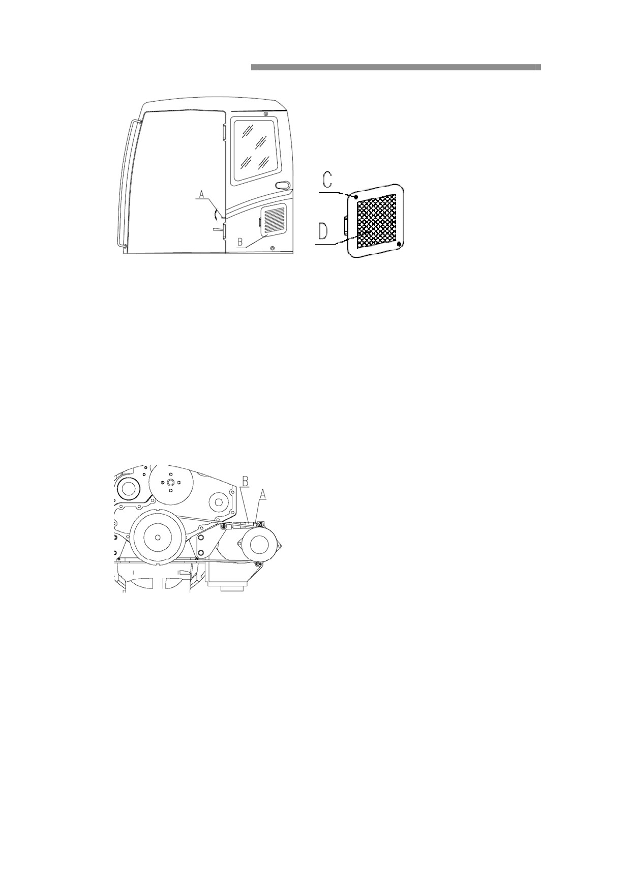
1.
Press the handle(A
,open the door(B)。
2.
Remove the nut (C),remove the filter(D)
3.
Clean the filter with compressed air.
4.
If the filter is damaged, or severely pollution, the filter should
be replaced with new.
5.
Install the filter and assembly in the reverse order.
Adjust the strap tensity of air conditioning
Import!
If the belt tension is incorrect, the compressor performance will drop, and the
belt and the compressor may be damaged.
With 10 kilograms force press two between the central parts of the pulley, if belt are
crushed 7 to 10 mm, show the belt tension force to normal.
1. Locknut screw locknut (A);
2. Adjust tension institutions (B) can adjust the belt tension force;
3. Twist the lock nut.
Crawler tension force
Check and adjust the crawler tension
Every 50 hours check crawler belt tension force
To check the crawler tension force, must be carry crawler belt from the ground.
Measurement, be very careful, in order to avoid falling or movement.
Take connection pin and bush usually wear , and work with the characteristics of the
soil conditions to change. To check the crawler tension force, and will keep the
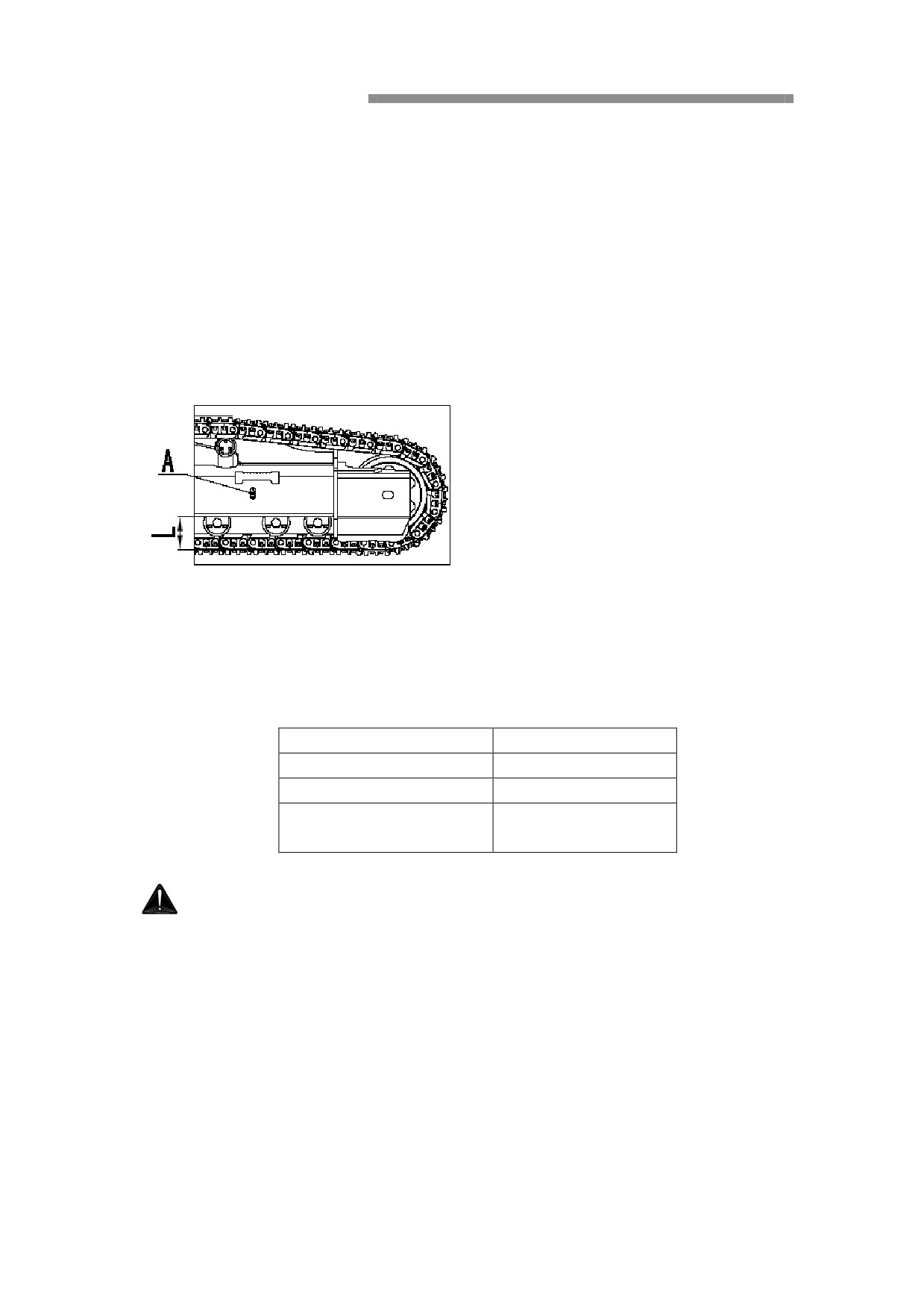
stipulated in the numerical, when in the wet sand or clay sand and clay work the
ground will stick in the chassis of the movement between the parts, can interfere with
the correct meshing between parts, which causes the interference and form big load,
the abrasive materials can be greatly increased the material wheel, pins/bushings,
guide roller, supporting roller and crawler fittings to wear away, and increase the load
and caterpillar tension force. Normally, packing effect is unable to control, can often
clean/remove filling material.
So to thoroughly clean the chassis, at least clean every day one or more, according to
work the soil conditions and decide.
Check
1. Use boom and arm uplift the crawler belt. Then, slowly operate handles.
2. "L", namely between crawler frame a bottom and crawler board surface on the gap.
3. According to the characteristics of the soil, adjust the tension force of crawler belt.
· According to the standard of soil properties determine the crawler tension
force.
Operating condition
L:Clearance (mm)
General soil
320-340
Rocky ground
300-320
Medium soil such as
340-360
gravel, sand, snow, etc
Adjust
Warning
Because of the high pressure of the oil cylinder grease effect, yellow nozzle may
be pop-up, loosen yellow nozzle, loosen don't more than a week.
At this time, don't loose yellow nozzle outside other parts. When operating keep
far away from the lateral and yellow nozzle installation position.
If you can not use the manual adjustment of the method of crawler belt tension force,
please and contact the special arrangement of authorized service center.
Improve the crawler belt tension force
1. The use of high pressure filling grease gun and through the position of A yellow
nozzle to filling grease.
2. Before check and adjustment of the crawler belt tension force, first the mechanical
walk backward and forward several times.
3. Check again for a tight force, if a tight force is not correct, should adjust again.
Reduce the crawler belt tension force
Warning
Because of the oil cylinder high in the role of the grease, yellow nozzle may be
pop-up, loosen yellow nozzle, loosen don't more than a week.
At this time, don't loose yellow nozzle outside other parts, away from the
installation position. If you can not use the manual adjustment of the method of
crawler belt tension force, please and contact the special arrangement of
authorized service center.
1. Gradually loosen yellow nozzle, so that emissions grease, loosen yellow nozzle is
not more than a week, when operating personnel must stand side, banned head near
access port, to ensure safety, because of the high pressure in the cylinder, grease and
refueling nozzle might suddenly pop-up.
2. Close yellow nozzle, but do not twist too tight, otherwise the joint be damaged. For
inspection by the adjustment of tension, mechanical walk backward and forward a few
times.
3. Check again for a tight force. If a tight force is not correct, should adjust again.
Crawler board bolt on tight
Every day to check the crawler board screw
If the crawler board loose bolts, crawler board often was damaged, so should always
check bolt looseness of degree, and will tighten bolts to provisions tightening torque
of 794 ± 39 N.
Tightening again
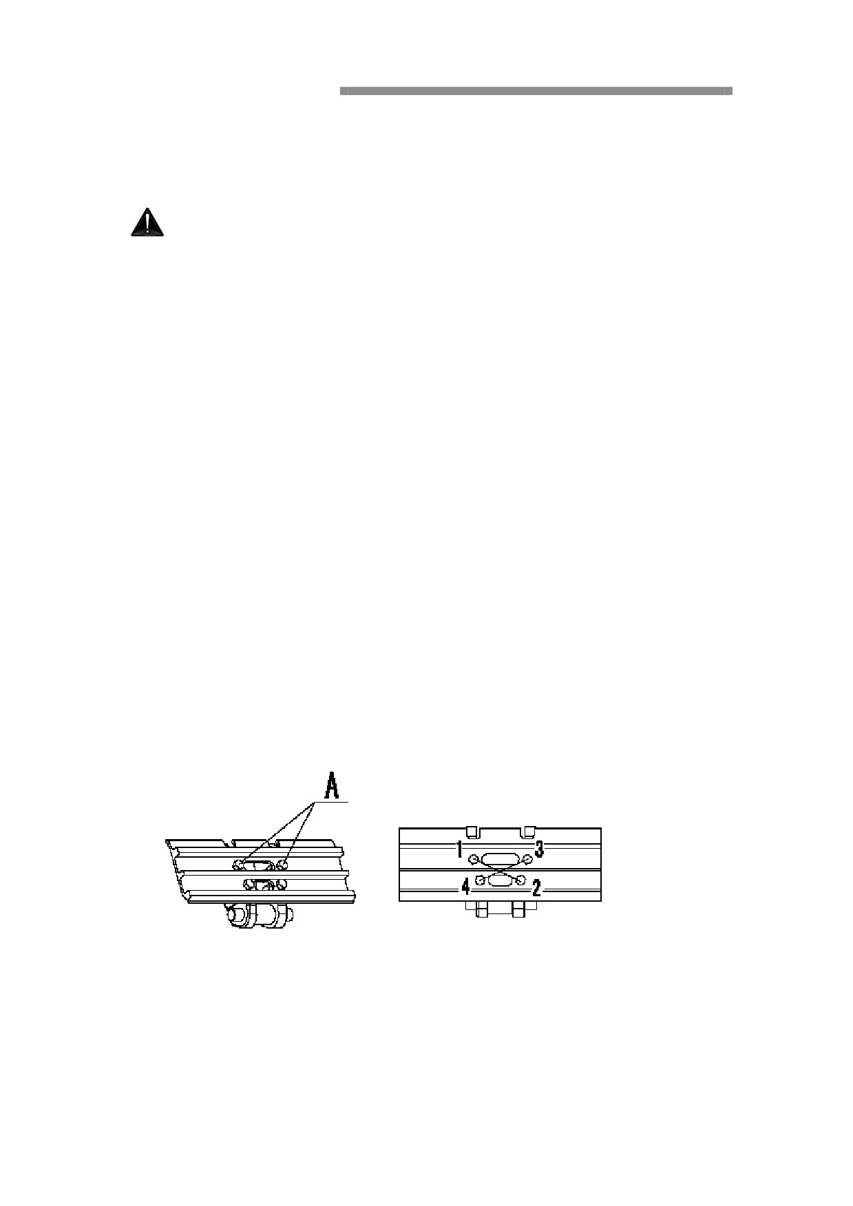
After use 794 + 39 N · m tightening torque tight, it should check the bolts, nuts and
crawler board whether sufficient contact.
Tight sequence
According to the above are shown in order to tighten bolts.
The bucket of clearance adjustment
Warning!
In the adjustment of the gap, due to incorrect operation and cause
work device is very dangerous, must put work device in steady state,
shut down engine and raise safety lock handle.
Clearance adjustment
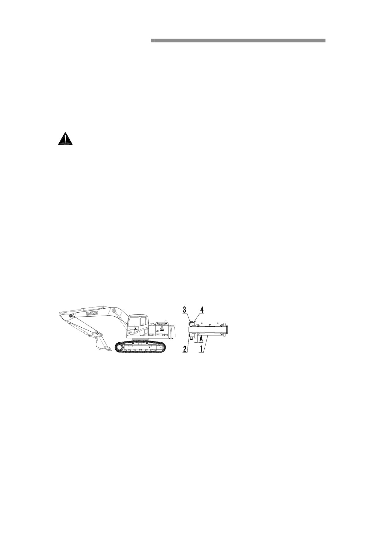
1. According to the following work device placed
2. Remove o-ring and measuring gap value (A), advance to move to one side to
measure the bucket is relative easy, use A feeler gauge more accurate;
3. Loosen the four bolts (2) and board (3), because use the open design, and two of
them will not be removed;
4. According to the gap value (A) remove the adjustment pad (4), such as A = 1.5 mm,
removal 1 mm and 0.5 mm adjustment pad (adjust pad (4) 1 and 0.5 two
specifications) when A less than A clearance adjustment pad thickness need not do to
adjust;
5. Tighten four bolts (2).
Replacement bucket tooth
Before the teeth wear and destroy, the bucket tooth should be replace.
Warning
Replace bucket tooth, always will put the bucket on the ground, that it is in the
most convenient to work state, and shut down engine.
Will a pad on below the bucket, and then put down the bucket, to keep the level.
Shut down engine, and up the safety lock handle, refer to 25 safety lock system ".
Warning
Replace in operation, often can have a fly pieces, so to wear goggles, gloves and
other protective equipment.
Replacement dipper teeth
1. Will a metal bar on the pin head, use hammer to knock out metal pin. Dismantle the
bucket teeth.
2. Note, want to use a root diameter is slightly less than the pin metal bar.
3. Clean install surface. The new bucket teeth into a tooth, by hand push the pin
, then use a hammer will knock into the lock pin to bucket teeth in the bucket.
Lubrication
Summarize
Lubrication is an important part of preventive maintenance. It increases the life of the
bearings and pins if lubricate the machine correctly. Lubrication chart can make the
lubrication easy and reduce the risk of forgotting the lubrication points.
There are two main purpose of lubrication:
-Supply grease for the bearings, and reduce friction between pins and bearing
bushings.
-Replace the old and dirty grease.
IMPORTANT!
Before adding the grease, please wipe the injection mouth and grease gun to
avoid filling of grease into the sand and dirt particles.
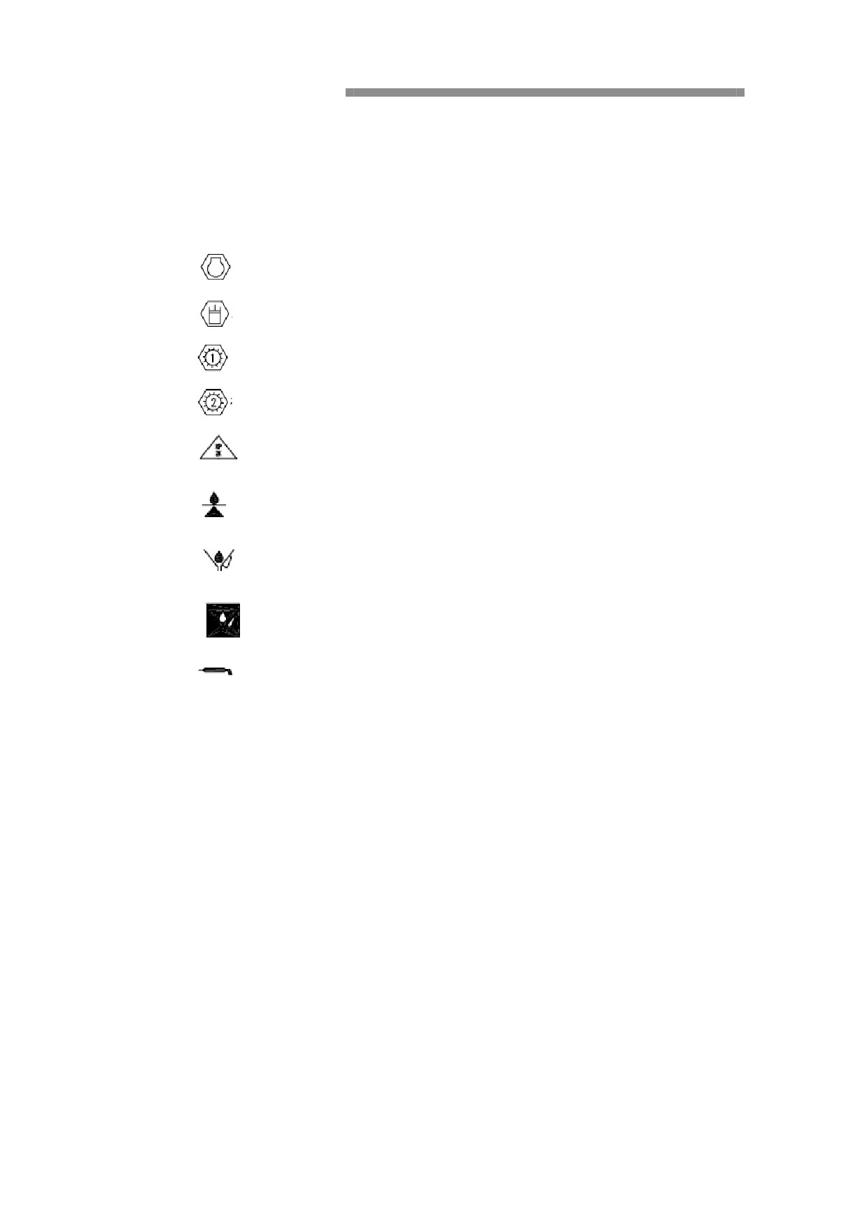
Symbols for lubrication and maintenance chart
The standard symbols for lubrication and maintenance charts, please refer to the
tables.
1.
Engine Oil
2.
Hydraulic System
3.
Swing Gear
4.
Travel Gear
5.
General Lubrication Points
6.
Check The Oil Level
7.
Change lubrication
8.
Change Lubrication For The First Time
9.
Lubrication
Lubricant And Maintenance Chart
10h (daily) and 50h, 250h, 500h, 1,000h, 2,000h maintenance
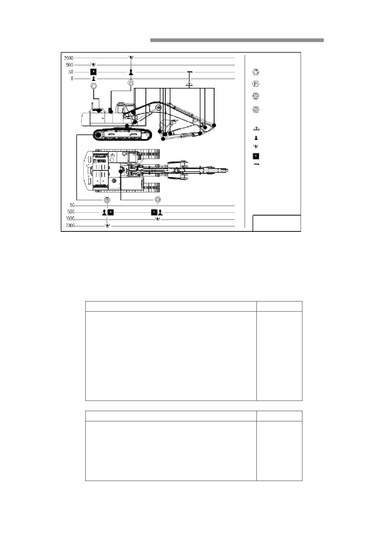
Engine 20L
Hydraulic system 500L
Swing reduction gear unit
10.5L
Undercarriage reduction
Gear unit 2×9.5 L
Routine lubrication point
Oil level check
Lubricant change
First lubricant change
Lubrication
Remark:
1.
Maintenance interval should be as
per owner’s manual.
2.
When servicing the excavator, park
it on a level ground, lower work
equipment, onto the ground and
turn off the engine.
Lubrication schematic
CAUTION: Customer shall assume the liability for any excavator malfunction resulting from
use of inferior oils.
Checking, Replacing and Lubricating
Measures
Page
Everyday= Every 10 hours
Checking:
Check the engine oil level
Check the cooler level
Drain the water in the separator and tank
Battery electrolyte level
Hydraulic oil level
The fixing bolts of the tracks
Alternator belt tension
Measures
Page
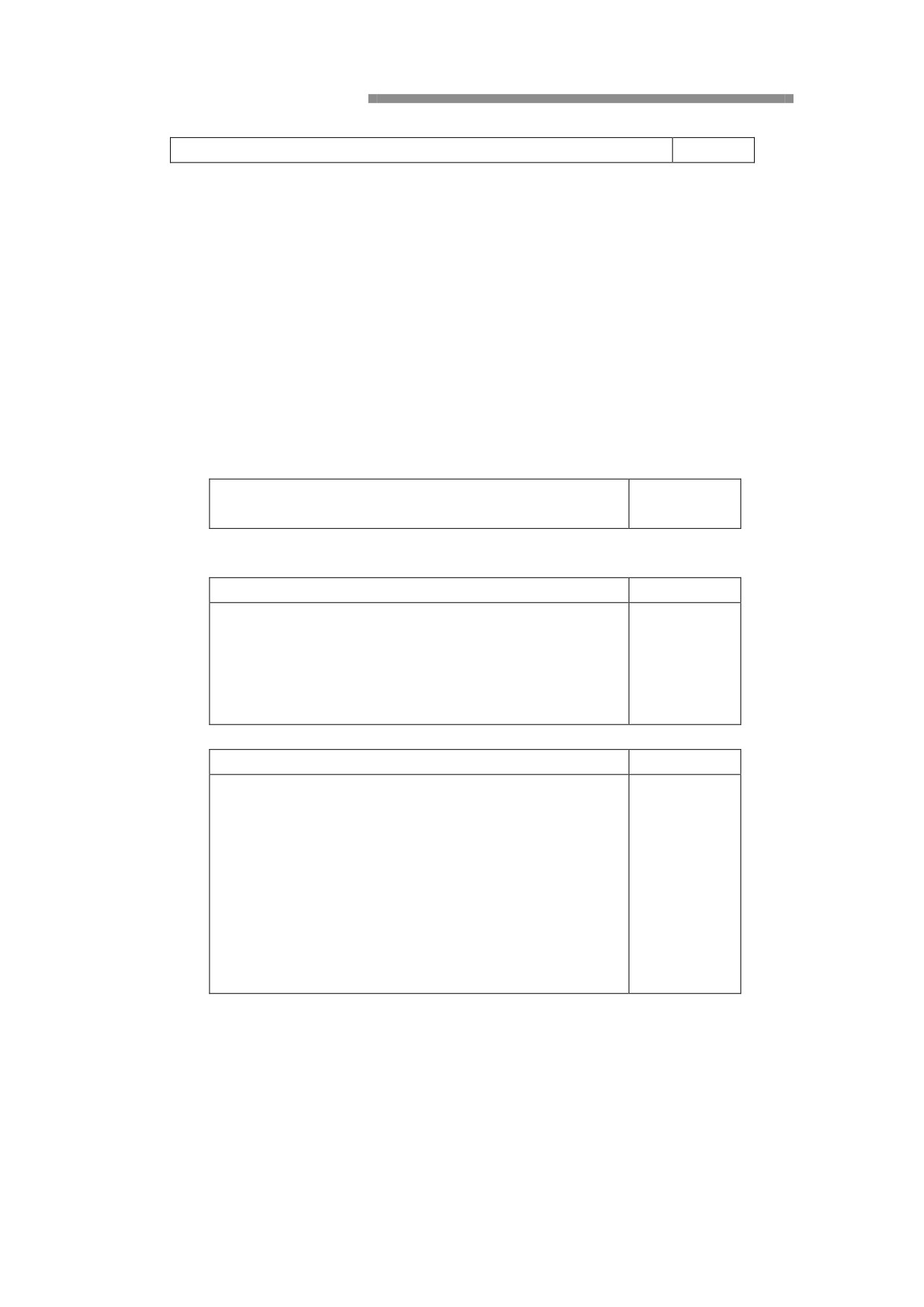
Everyday=Every 50 hours
After completing routine maintenance work:
Checking:
Tension of the tracks
Lubricating:
Lubrication to the working device
Measures
Page
Adjusting:
Check and adjust the track tensity
Measures
Page
Every 100 hours
After completing every day or 50 hours
maintenance work:
Cleaning
(If necessary)
Sediment in the fuel tank
Measures
Page
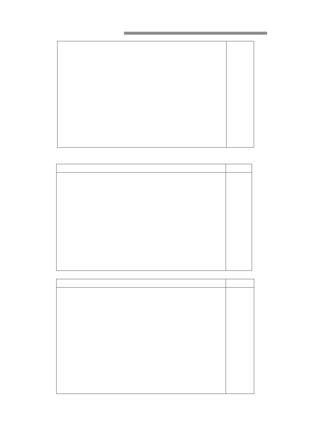
Every 250 hours
After completing every day or 50, 100, 200 hours
maintenance work:
Checking:
Fan strap tension
Swing motor oil lever
Travel motor oil lever
Lubricating:
Lubricating the swing circle
Every 500 hours
After completing every day or 50, 100, 200, 250 hours
maintenance work:
Checking:
Coolant
Lubricating the gear of the swing circle
Replacing:
Engine lubricant and filter
Replace the hydraulic suck filter core
(1st after using the 250 hours)
Cleaning:
Radiator, hydraulic oil condenser and condenser fins
Measures
Page
Every 1,000 hours
After completing every day or 50, 100, 200, 250, 500 hours
maintenance work:
Replacing:
Oil filter
Fuel-Water Separator
Hydraulic components of pilot filter
(1st after using the 250 hours)
Oilof the Swing motor
(1st after using the 500 hours)
Cleaning:
Suck filter(Hydraulic tank)
Measures
Page
Every 2,000 hours
After completing every day or 50, 100, 200, 250,500, 1,000
hours maintenance work:
Replacing:
The main element of air filter
The protection element of air filter
Hydraulic oil
The oil of travel motor
(1st after using the 500 hours)
Coolant
Cleaning:
The vent valve on the hydraulic tank
(If necessary)
Measures
Page
Every 3,000 hours
After completing every day or 50, 100, 200, 250,500, 1,000,
2,000 hours maintenance work:
Replacing:
Coolant
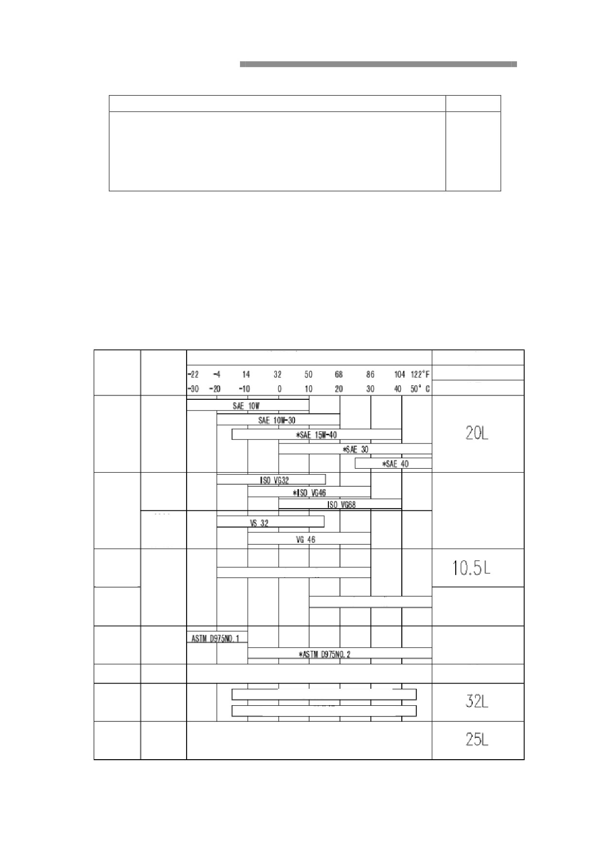
Specification
Recommended lubricants
Recommended lubricants
Ambient temperature
Specification
Position
Type
Capacity L (Gal.)
Total volume
Engine
Engine
lubrication
lubricant
**
Mineral oil
250L
Hydraulic
oil tank
***
Biodegradabl
420L in total
e oil
Swing drive
***
*SAE 90 and APIGL 4 or GL5
Gear oil
Traveling
drive
*SAE 140 and APIGL 4 or GL5
2X5.4L
Fuel tank
Diesel oil
360L
Swing
Grease
*Multipurpose NLG12
24L
support
Multipurpose NLG12
Axis pin
Grease
track
*Molybdenum disulfide NLG12
Cooling
Antifreeze
50% antifreeze
50% water
system
*: Filling in the factory
**: High viscosity index or better resistance to water hydraulic oil
***: With EP additives
****: Biodegradable hydraulic oil is made of synthetic resin
ASTM:美国测试与材料学会
SAE:汽车工程师学会
ISO:国际标准化组织
API:美国石油学会
Total: Total volume, including the retained part of the piping and other
components
Filling volume: During machinery examination and maintenance, filling the
storage tank that it required
Notice:
Please use the SAE 10W-30 and SAE 15W-40 engine oil, start the engine if the
ambient temperature is below 0 ℃. Please do thi s even if the temperature reached
10 ℃ during the day.
Please replace once every 500 hours, if use fuel with a sulfur content of less than
0.5% and not less than the requirement of GB252-94
NOise level
Noise level of the cab.
The noise level meet the ISO 6395和98/37/EC, when close the cab door.
The noise level around the machine (see the values shown in the cab at the front
windows) according to ISO 6395: 2000/14/EC.
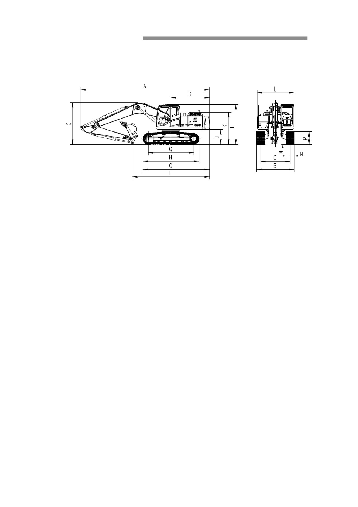
Dimensions
mm
A-------------------------------------------------9549
B-------------------------------------------------2800
C-------------------------------------------------3073
D-------------------------------------------------2853
E-------------------------------------------------2932.5
F-------------------------------------------------5726
G-------------------------------------------------4943
H-------------------------------------------------4160.5
J-------------------------------------------------1075
K-------------------------------------------------2348
L-------------------------------------------------2736
M-------------------------------------------------468
N-------------------------------------------------600
O-------------------------------------------------2200
P-------------------------------------------------946
Q-------------------------------------------------3360
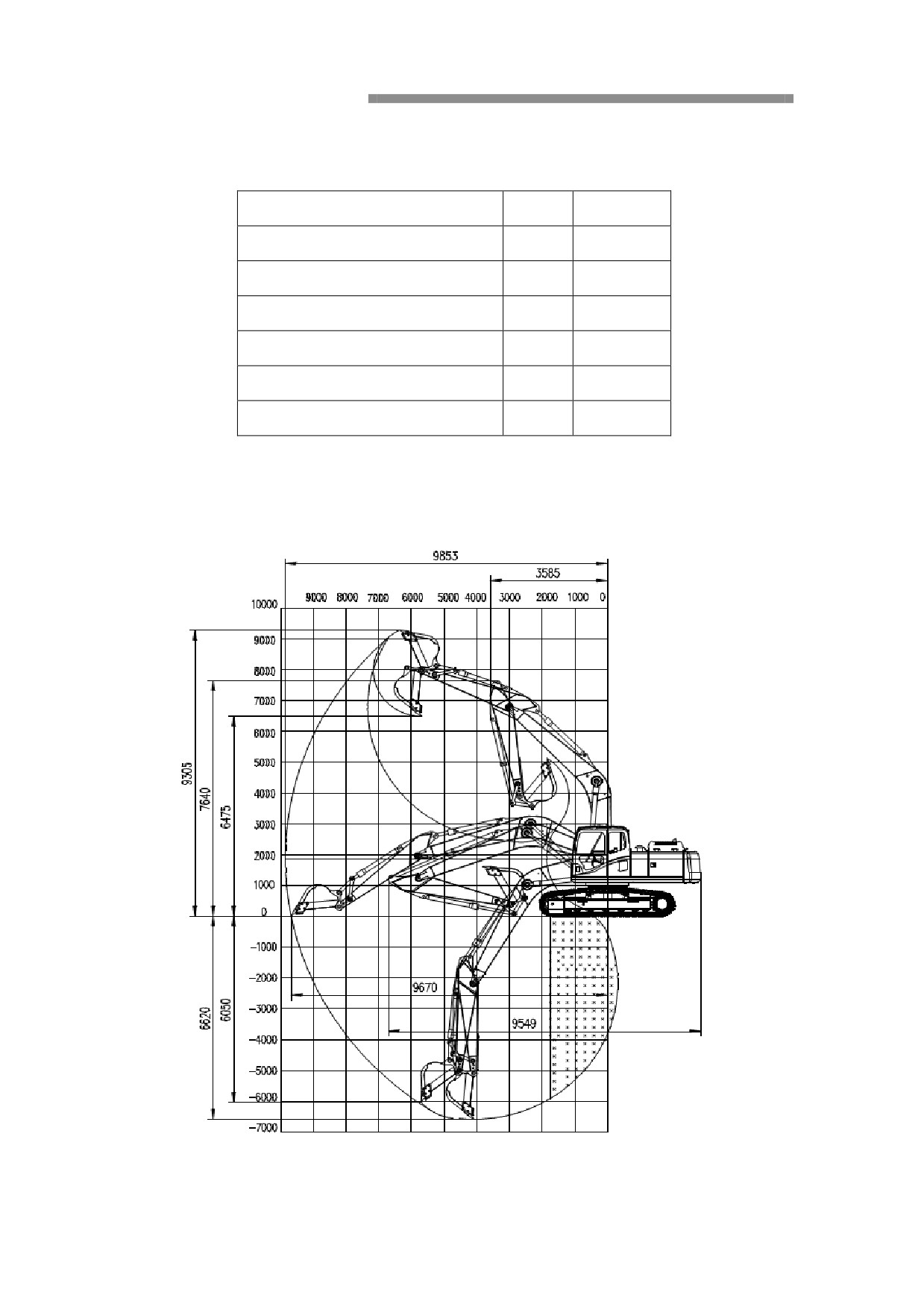
Standard equipments and Digging force
Stick lengths
m
2.919
Max. digging depth
m
6.62
Max. digging radius
m
9.853
Max. reaching height
m
9.305
Max. dump height
m
6.475
Digging force of arm cylinder
kN
92.5
Digging force of bucket cylinder
kN
115
Working Ranges
Operating Weight and Ground Pressure
Operating weight includes basic machine
( With
5.7m boom, 2.919 arm, and
0.36-1.0m³bucket)
Track width (mm)
600
Weight ( kg)
20500
Ground pressure (KPa)
45
Standard equipments with Boom 5.7m, Arm2.919m and 0.36-1.0m³bucket.
Warning: Only after getting the permission of our company that the optional or
special parts can be install on the machine.