Shantui SE210 Hydraulic Excavator. Operation & Maintenance Manual - page 1
Unsafe use of this machine may cause serious
injury of death. Operators and maintenance
personnel must read this manual before operating
or maintaining this machine. This manual should
be kept near the machine for reference and
periodically reviewed by all personnel who will
come into contact with it.
SHANTUI CONSTRUCTION MACHINERY CO., LTD
THE PEOPLE’S REPUBLIC OF CHINA
I
Warning!
There should be no any operation or maintainace before reading and
comprehending this manual.
Both of right maintainance and operation is very important to
machine’ssafety, reliability and operability. The way of maintaince
and operation in this book is the most efficient.Following this way
would be helpful to insure equioments’ reliability, economy and
efectiviness. To reduce the rate of casualties, equipment damage
caused by improper operation and risk of unsafe factor, please pay
attention to “notice” and “caution”.
Notice:
This book has been modified to fit all market. But the special
equipments are not contained, for these maybe not for your machine.
We keep the right to perfect prodect’s specification of technical
parameters, standard, designs, operation and maintaince, and also
keep right to improve these products. And please forgive us that we
would not notice you about the previous products having no such
equipments.
Safety requirement
Operate this machine under governmental rules. So the following operation safety
omformation is just advice.
The following marks, apper with words means:
III
Warning!
Keep in mind, this is related to your own safety!
Ignoring this danger would cause accident, damage and
even death.
The operator has the responsibility to make sure all the marks are on
the machine and readability.
Be familiar to this machine’s function and limitation.
Maintaince and operation
We JCM are responsible for the following situation:
·operate and maintaince the machine follow this book
·service and maintaince of every part is on time
·use the lubricating oil and fuel oil recommended by this book
·Protective seals are in good condition, or adjusted or reinstall byauthorized dealer.
·all the change and maintaince should follow rules of JCM.
·use the original sapre parts and equipments, or from supplier confirmed by JCM.
Warning!
The operator should have enough skills and be familiar tothis book
before operation.
Untrained operator may caus terrible damage and even death.
Do not operate machine without this book.
Before operation, be familiar to marks, plates and this book.
Assembling of communication equipments
All the optional communication equipments should be assembled by trained people
and follow rules of JCM.
IV
Protection of EMI
This machine has been tested follow EU89/336 EC, so it is very importantto test
all the unauthorized equipments before or after working, for they may disturb
electronic system.
Mobile telephone
A mobilephone should be assembled permantent in electronic system to get the best
function. And there should be an antenna in cabin assembled follow manufacturer’s
advice. When the telephone is working, ie should always send information to base
station, even out of working, so it should not be put inside of electronic equipments.
Rule
Assemble under the following rules:
·antenna’s palace shoud be fit to around situation
·antenna must be coaxial type. Keep the cable in good condition and has good
electricity contect.
·Between the antenna fixture and machine must be metal without surface dirt and
oxide. Avoiding corrosion after assembling to keep in good contact.
·Keep distance between disturb cable and disturbed cable, disturb cable contains
communication equpments’ power and antenna cable. Disturbed cable is to
connect machine’s electronic equipments. For the metal has function to shield,
these cables shoud be close to grounded metal.
V
Catalogue
Foreword
Safety requirement
.................................................................................................................. III
Maintaince and operation
........................................................................................................IV
Assembling of communication equipments
............................................................................IV
Catalogue
........................................................................................................................................VI
Introduction
.................................................................................................................................. - 1
-
Summarize
........................................................................................................................... - 1
-
Plate and lamination
............................................................................................................. - 2
-
Repair and maintenance
..................................................................................................... -
10 -
General Information
........................................................................................................... -
11 -
Instruments and controls
.................................................................................................... -
13 -
Overview
.................................................................................................................... -
13 -
2. Fuel display area
-
16 -
3. Coolant temperature display area
........................................................................... -
16 -
4. Calendar and clock display area
............................................................................. -
16 -
II. Description of key board
.................................................................................... -
17 -
1.
Troubleshooting
-
21 -
If selecting Troubleshooting, then you will enter the frame shown right:.................. -
22 -
2.
Clock display and adjustment
-
22 -
3.
Maintenance time records (optional).............................................................. -
23 -
4.
System Help
....................................................................................................... -
23 -
5.
Restore Factory Settings
-
24 -
Controls
.............................................................................................................................. -
25 -
1.
Control lever (LH): This lever is used for swing and dipper operation.......... -
25 -
2.
Control lever (RH): This lever is used for boom and bucket operations.
....... -
25 -
3.
Travel lever/pedal
............................................................................................... -
26 -
Safety lock system
-
26 -
Operator seat
.................................................................................................................... -
27 -
Safety belt
-
28 -
Cab and window
............................................................................................................... -
29 -
Fire extinguisher and emergency exits
........................................................................... -
30 -
Cab lighting
-
30 -
Cigarette lighter.................................................................................................................. -
30 -
A/C system
......................................................................................................................... -
30 -
Radio/MP3 player
............................................................................................................ -
31 -
Operating instruction
-
32 -
Introduce
........................................................................................................................... -
32 -
Grinding-in instruction.................................................................................................... -
32 -
VI
Safety and Responsibility
- 33 -
Machine transportation
................................................................................................... - 37
-
Dismantlement fot transportation
.................................................................................. - 38
-
Overall dimensions:
- 38 -
Detachable parts for easier transport:
......................................................................... - 39
-
Hoisting machine
.............................................................................................................. - 39
-
Counterweight installation
.............................................................................................. - 40
-
Changing bucket
- 41 -
Selection of track shoes...................................................................................................... - 43
-
Explosion-proof valve(Optional part)
....................................................................... - 43
-
Before operation
................................................................................................................. - 44
-
Start Switch
........................................................................................................................ - 46
-
Start the engine................................................................................................................... - 47
-
Operation............................................................................................................................ - 48
-
Operation completed
.......................................................................................................... - 50
-
Parking machine................................................................................................................. - 51
-
Hauling method
.................................................................................................................. - 52
-
Work with the bucket
......................................................................................................... - 53
-
Exit from the muddy ground
.............................................................................................. - 54
-
Optional Components
- 55 -
Maintenance of safety
................................................................................................................ - 58
-
Introduction
........................................................................................................................ - 58
-
Maintenance position
......................................................................................................... - 59
-
Statement
............................................................................................................................ -
60 -
Prevention measures
-
62 -
Storage battery
................................................................................................................... -
66 -
Air conditioner
................................................................................................................... -
68 -
Handrails and pedals to be on/off the machine
.................................................................. -
70 -
Repair and maintenance
............................................................................................................. -
72 -
Engine
................................................................................................................................ -
72 -
Fuel system
........................................................................................................................ -
74 -
Intermediate cooler
-
76 -
Turbocharger
...................................................................................................................... - 76
-
Air filter
- 77 -
Lubricant specifications: See the 99 recommended lubricant.
........................................... - 93 -
Air Conditioning
................................................................................................................ - 99
-
Lubrication
....................................................................................................................... - 104 -
Summarize
- 104 -
Symbols for lubrication and maintenance chart
....................................................... - 105 -
Lubricant And Maintenance Chart
........................................................................... - 105 -
Checking, Replacing and Lubricating
...................................................................... - 106 -
Specification
- 109 -
Recommended lubricants
................................................................................................. - 109 -
Recommended lubricants
................................................................................................. - 109 -
VII
Dimensions
- 111 -
Standard equipments and Digging force
.......................................................................... - 112 -
Working Ranges
............................................................................................................... - 112 -
VIII
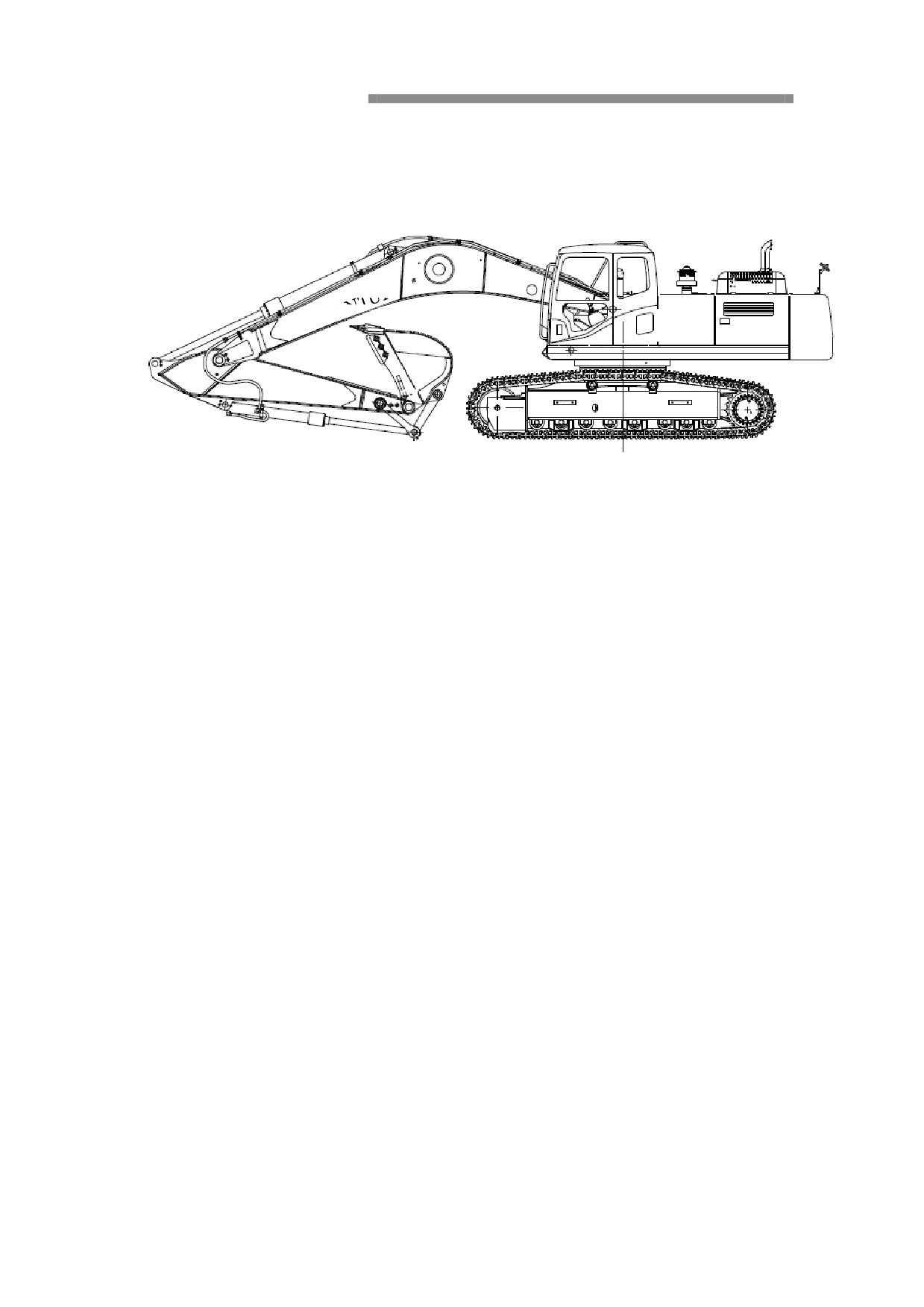
Introduction
SHANTUI
Summarize
Designed function
This machine is designed to work in normal situation. In special and dangerours
condition, operator should follow special reles and equipped special equipments.
Please contact dealer to get more information.
Engine
The engine is 6 cylinder, 4 stroke, direct injection, turbocharging, intercooling
and water-cooling, with 5.9 L output volume, the model is Cummins B5.9-C
Electronic system
This system consists engine, charging, monitoring, engine-pump control and air
condition sustem.
The speed is controlled by segmented increased continues button andautomatic
idling system. Idling and increased speed system would reduce engine’s revoling
speed after operation in 7 seconds, and increases the speed to the designed.
Hydraulic pump
Hydraulic pump component consists two variable cam-type pump connected by two
multiple keys and a quantitative gear pump, driven by engine.
Pump consists valve shroud and two groups of rotors and swash plates.
Two cam-type pumps’ output volume is controlled by regulator
, engine’s is
controlled by solenoid controlled proportional relief valve.
Main Control Valve
The control valve consists of 9 spool valve blocks, including 4 spool valves that are
used for excavating gear, 4 spool valves for confluence and continuous driving, and
1 spool valve for optional equipment, 1 main relief valve, several outlet relieve
valves, and several balance valves and one-way valves. All these valves are
controlled by the servo-hydraulic system.
Travel Motor and Reduction Gear Unit
The travel motor is a cam-type axial piston including brake valve block and parking
brake. The rear flange contains counterbalance valve, one-way valve, switch relief
valve, and displacement conversion valve. The reduction gear unit consists of master
gear, planetary gear, pinion, and casing.
Swing Motor and Reduction Gear Unit
The swing motor unit comprises a cylinder block and a piston assembly located
in the block. Guided by the return plate and spring, the piston assembly can slide
onto the swash plate smoothly. There is a relief valve for buffering and a cavitation
inhibitor valve used to prevent cavitation erosion on the cylinder head unit. The
reduction gear unit consists of sun gear, planetary gear, pinion, and casing. The
power to the output shaft of the swing motor is transmitted to the pinion after motor
speed is reduced and torque is increased through the sun gear and planetary gear.
Plate and lamination
Plate
The following explanation and words should be on machine.
The product’s model should be marked out when its spare parts are orded.
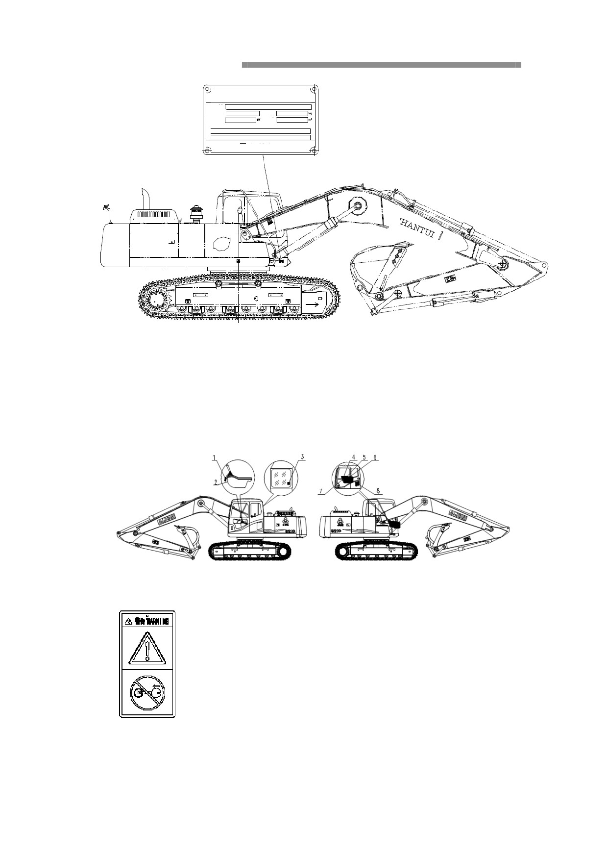
1. Plate(show model, number, weight, engine ourput mark) is on theleft side of
upper frame which is close to body frame.
HYDRAULIC EXCAVATOR
MODEL
SERIAL NO.
MASS
ENGINE
CAPACITY
POWER
Product identification Number
SHANTUI
SHANTU
I
2. Engine’s model and number and so on is on the plate where is on
theengine’s right sid (from fan).
Information and caution mark
The following is the caution and words which should be foune on machine.
1.Do not start engine
2. Safety lockout
Refer to “safety lockout system”
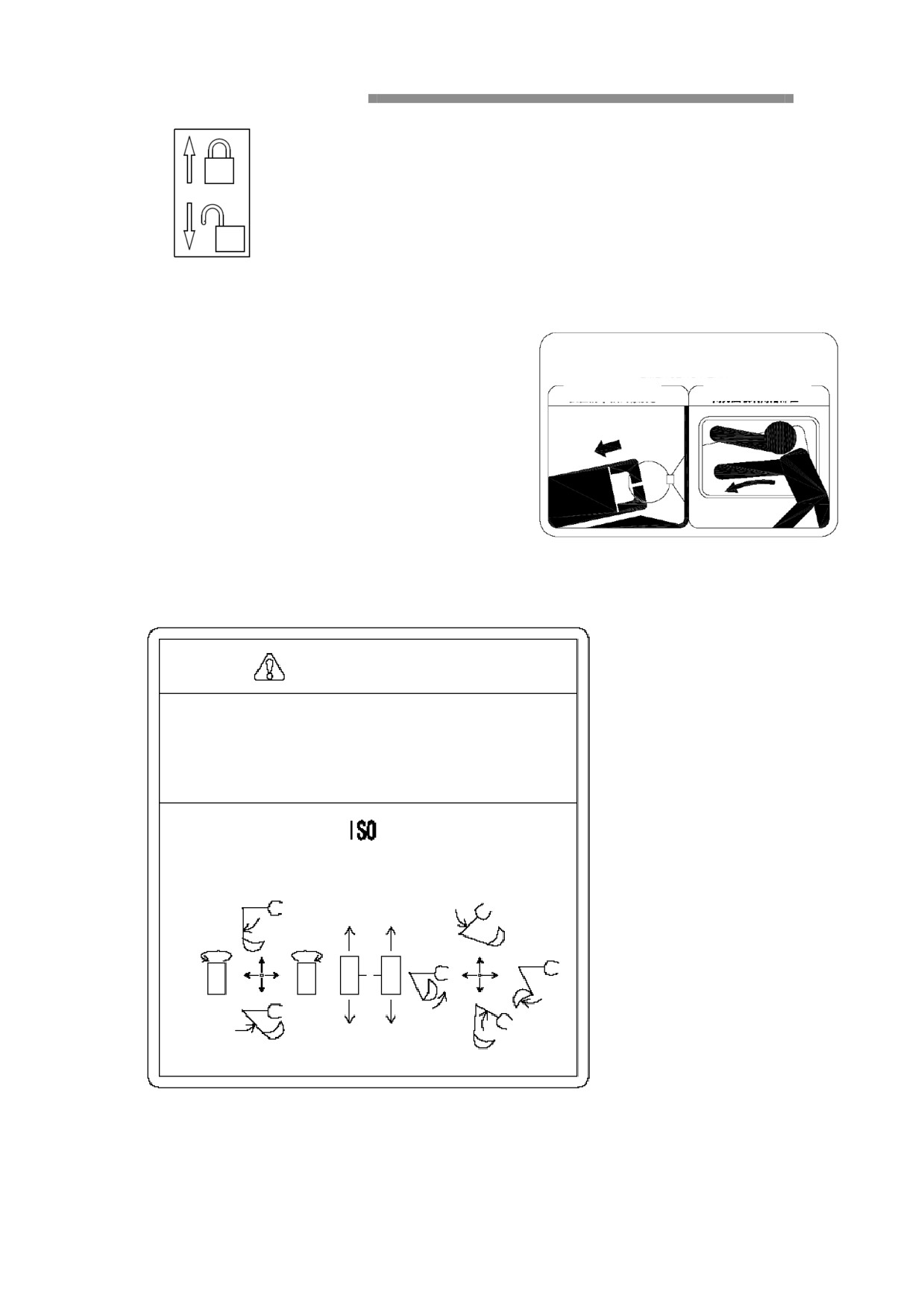
3.
Emergency exit
EMERGENCY EXIT
Please refer to “Escape in case of emergency”.
Hold the steel loop and draw
Press corners of the glass hard
out the rubber core
4. Operating options
Warning
To prevent personal injury or death resulting from incorrect operation, please
identify the operating condition of the machine and the operation mode
displayed when you operate the machine. When identifying the operating
condition of the machine, please pay attention to its peripheral portion while
operating slowly.
5. Accessories recommended table
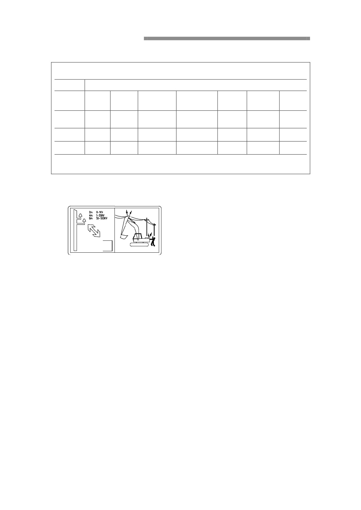
Table of Recommended Accessories
Table of Recommended Accessories for SE210 Excavator
Location
Swing
Undercarriage
Antifreeze
Air
Engine
Fuel
Hydraulic oil
reduction
reduction
solution
conditioner
gear unit
gear unit
API CH-4/
Sulfur
Accessory
API GL-4
API GL-4
SJ SAE
content
ISO VG46
-45℃
R134a
requirement
SAE 90
SAE 85W-90
15W-40
<0.5%
Recommended
Premium
Special hydraulic
Special antifreeze for
-10# or -35#
Mobil GX
Mobil GX
-
variety
Blue
oil for SHANTUI
SHANTUI
Capacity:
Amount
20L
420 L
Capacity:25 L
4.4 L
2X5.4 L
0.9Kg
360L
Description:
The various types of accessories selected in the table are generally required at delivery. For cold northern and hot southern areas, you can adjust the
recommendations in accordance with the requirements of the Owner’s Manual depending on climate conditions.
6. High voltage
7. Maintaince
Service and maintenance
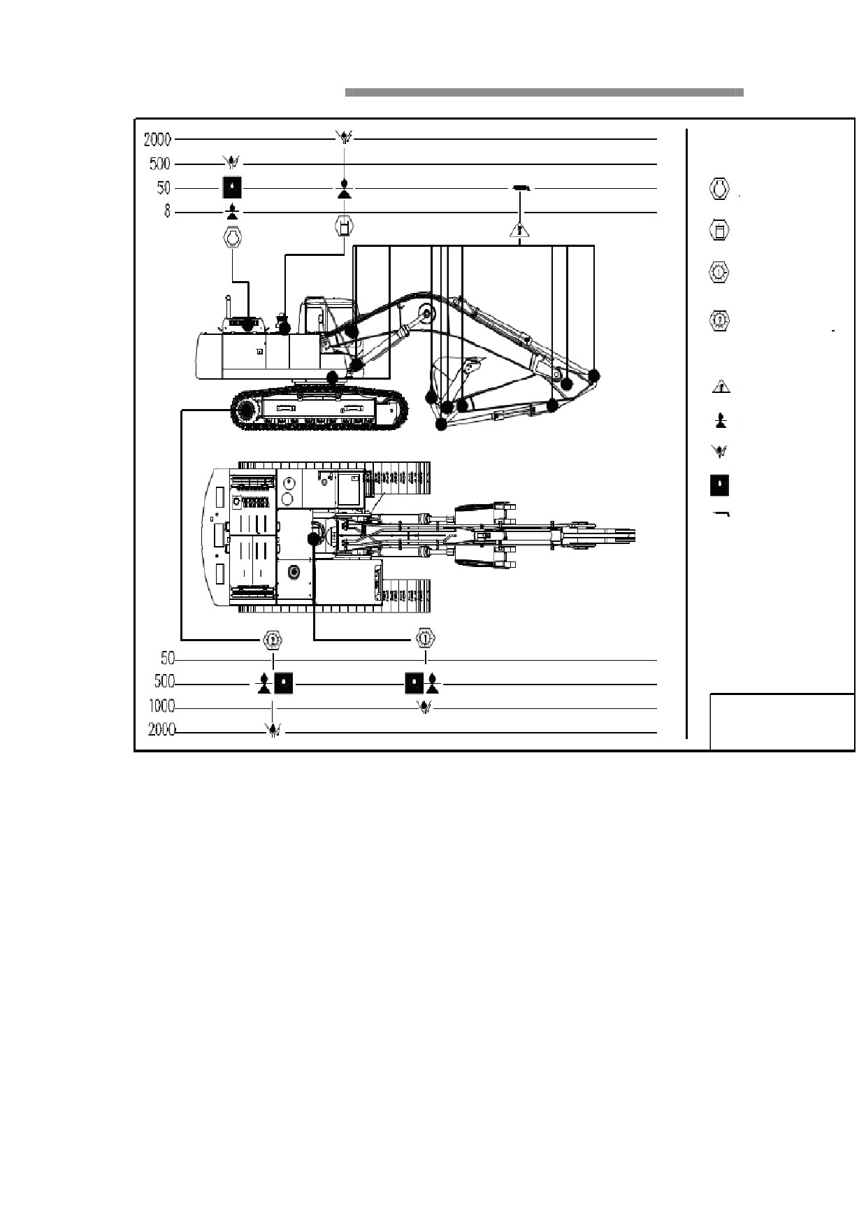
Engine 20L
Hydraulic system 500L
Swing reduction gear
unit 10.5L
Undercarriage reduction
gear unit 2X9.5 L
Routine lubrication point
Oil level check
Lubricant change
First lubricant change
Lubrication
Remark:
1.
Maintenance interval per owner’s manual
2.。 When servicing the excavator, park it on a
level ground, secure the work equipment,
and turn off the engine.
on a level ground, secure the work equipment,
and turn off the engine.
Lubriczation
schematic
8. Note
Caution
Before operating the vehicle, you must
If any hydraulic cylinder or a part of the
read the Owner’s Manual carefully.
circulating system is removed, be sure to
Before starting the vehicle, check it.
follow the procedure below to bleed it
When any unsafe factor exists, do not
when reinstalling it.
start the vehicle.
1.
Idle the engine at low speed.
The personnel must make clear the safe
2.
Extend and retract the cylinder piston for
distance to high-tension lines.
4-5 times at first and stop it at
100m
Before leaving the driver’s seat, you must
before its stroke end.
observe the following:
3.
Then move piston of each cylinder to
Lower the work equipment to the ground.
respective stroke end for 3-4 times.
Lock control lever with safety lock, and
For details of track adjustment, refer to
stop the engine.
the Owner's Manual.
When jacking up the vehicle body using
After a long-stay parking, you must
boom or stick, do not allow anyone to
follow the procedure below when starting
enter under the body.
the engine.
When parking on a slope, be sure to put
1.
Turn the starting switch of the engine to
stoppers under tracks.
the "ON" position.
When adjusting track tension, do not
2.
Start the engine.
slacken the valve for more than 1 turn.
Select engine oil according to ambient
When exceeded,
the
internal
temperature. Please refer to the Owner's
high-pressure grease may blow out.
Manual.
When stopping the engine, idle it with
minimum throttle opening for 5 minutes
before stopping it.
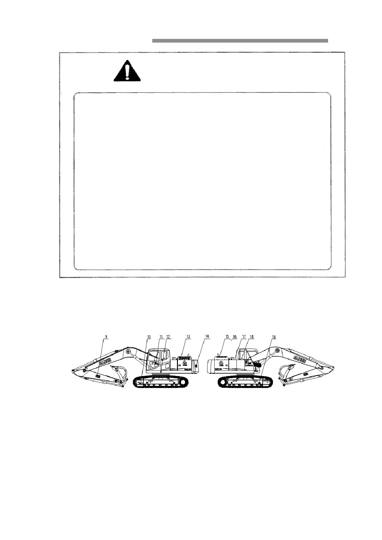
9. Keep distance
Working area, keep in distance!
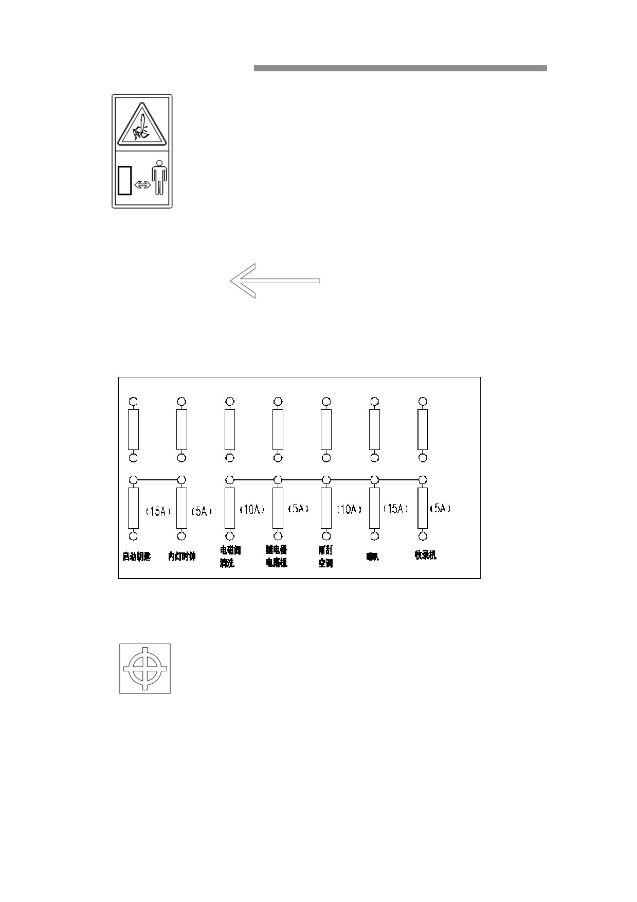
10. Travel direction
11. Fuse parameters
12. Swing location
13.Warning!Banned trample, prevent slip
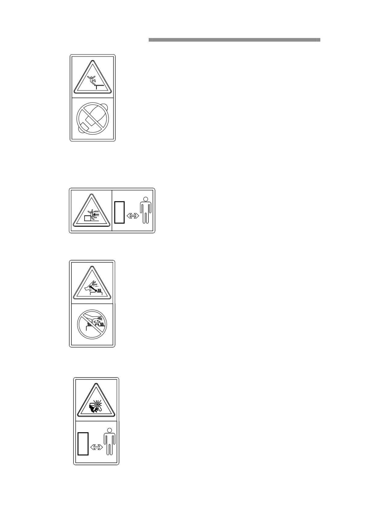
14. Keep distance
In swing radius, keep in distance!
15. Warning! Cooling liquid is with high heat and pressure, be careful of scald.
16. Warning! Turnng, keep in distance
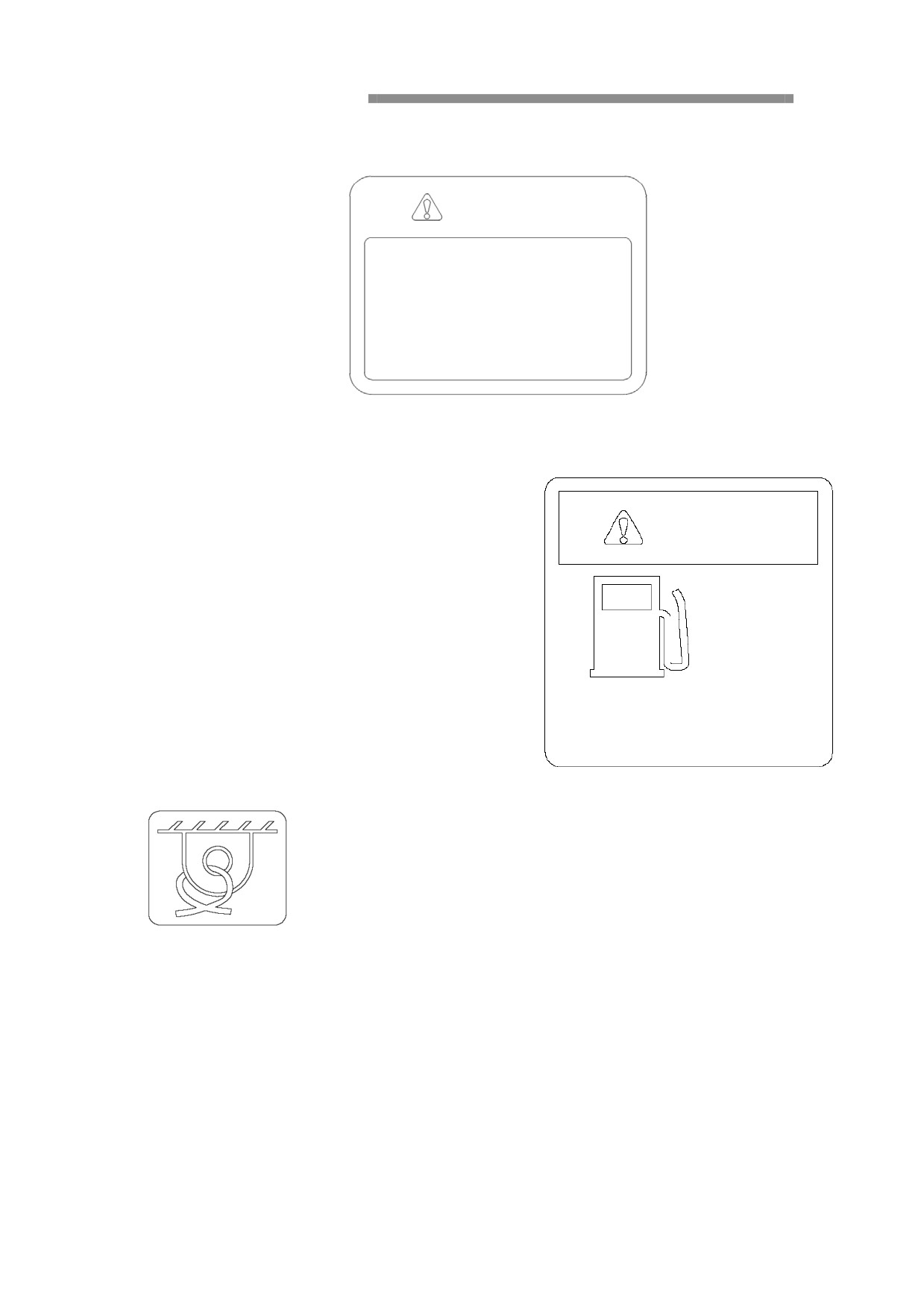
17. Caution! Hydraulic oil is with high heat and pressure, be careful of scald.
CAUTION
1.
Be sure to turn off the engine before
opening its hood.
2.
Do not open the hood when oil temperature
is too high.
3.
Open the hydraulic oil tank cap slowly to
release its internal pressure completely.
4.
Do not loosen the drain plug when oil
temperature is too high.
18.
Dangerous! Inflammable and explosive! Keep
fire away!
DANGER
Fuel
Diesel oil
When refueling, be sure to stop the
engine and keep safe distances from all
lights and open flames.
19. Lifting and fixed position.
Repair and maintenance
Overview
In order to reduce the cost of using the machine as much as possible, you must do
the machine with good maintenance and repair. Repair and maintenance intervals
apply to normal environmental and working conditions of the machine, the operator
can do the maintenance work described in the "Manual", further adjustments and
repairs should be done by authorized service center or manufacturer.
Delivery and Inspect
The machine has completed the test and adjusts accordingly before leaves the factory.
According to the instructions in this manual, the dealer should also do further
"delivery inspection." before the delivery of the user.
Warranty inspection
It is very important to inspect the machine regularly at an early stage. The contents
include: checking the degree of tightening bolts, the set value and actual value to
compare and make minor adjustments.
Therefore, the follow-up examination is divided into three phases: The first is in 500
hours later, the second is in 1000 hours later, and the third time is in 2000 hours later.
Strong construction machinery co.,ltd has the right to make changes of the inspection
time without prior notice.
Service
State testing and maintenance program
In addition to the measures described in manual and maintenance program,
authorized service center also provides special state-based testing service content, as
well as the general state of the machine.
You can get the information about the content of the authorization from the nearest
Authorized Service Center.
General Information
U.S. federal "Clean Air Act."
The federal Clean Air Act Section 203 (a) (3) section shall prohibit removal of air
pollution control device, or make the inspection and approval of non-road engines
convert into the form without checking the structure.
Federal regulations at 40 CFR Part 89 1003 (a) (3) (i) section supplements the
non-road engines of the Clean Air Act, as follows:
Prohibit the following acts and the reasons:
Before the sale or delivery of the machine prior to the end user, unauthorized
removal or disposal of equipment used in line with the regulations, components,
non-road engines or equipment;
After the sale or delivery to the end users, intentional removal or disposal of such
devices or components.
Violation of this law shall be punishable by a fine of $ 2,500;
Unauthorized modification to the fuel system to increase the certified calibration of
engine power or torque is also an offense.
It is not allowed to change the passed certification of non-road engines, otherwise it
will cause the current engine models that meets the federal standard does not match
the overall machine system.
User support
Strong construction machinery co.,ltd is willing to provide to ensure better
implementation of the emission control system warranty.
If you do not enjoy the warranty service that should get according to the emission
control system warranty, please contact the nearest regional office for assistance.
The general-purpose of Non-road engines
Prerequisite for the maintenance of the machine according to the set "Manual" in the
manner prescribed, and only use the specified fuel and lubricants.
Maintenance of non-road engines
Non-road engines are belonging to conventional design; any local sales agents can
finish maintenance tasks that described in this manual require non-road engine
emission control.
Particularly recommend that users comply with the "basic preventive maintenance"
section of the non-highway engine maintenance instructions.
Such maintenance includes the maintenance of the engine emission control devices.
In order to carry out with written proof of status of regular maintenance, Strong
construction machinery co.,ltd recommends that users retain all maintenance records
and receipts. These records and receipts for all purchases should be handed over to
users of non-road engines.
Services provided by local distributors
Local dealers are equipped with the manufacturer's original spare parts, special tools,
the latest technical information and well-trained service technicians, which have the
ability to provide you with quality, reliable service.
Please notify your local dealer of maintenance service requirements. According to
your needs, they will make specialized maintenance program.
For regular maintenance work, you had better to get in touch with local dealers,
mutually agreed time, to deploy the necessary equipment and maintenance
technicians to repair your machine in order to ensure and improve the utilization of
your machine.
Preventive maintenance and maintenance plan
In order to maintain the reliability of the engine, control exhaust emissions, noise,
radiation, it is very important to maintenance, inspect and adjust the engine regularly.
Fuel System
Suggestions about the fuel:
The fuel must be clean, safe distillation, stable and non-corrosive. Optimal choice of
fuel in the combustion efficiency and minimum wear and tear, the distillation range,
Hexadecane number and sulfur content is the most important factor.
To cold characteristics and Hexadecane number, the engine working conditions and
ambient temperature affect the fuel choice.
In cold climates, such as temperature below 0 ℃, it is best to use lighter distillation
or higher Hexadecane number. (Final boiling temperature of 349 ℃ and minimum
Hexadecane number of 45).
In order to avoid the formation of too much precipitation, and reduce the exhaust
emissions of sulfur dioxide to a minimum, you should choose the fuel with sulfur
content as low as possible, we recommend the use of diesel engines should meet the
American Society for Testing and Materials ASTM requirements: D975NoID (CB)
or No.2D (TT) and not less than 42 Hexadecane number, sulfur content by weight
not more than 0.5% of the fuel.
Check fuel leakage
If the engine is running at high idle, you should inspect all fuel fittings and hoses by
eyes.
Check the fuel hose situations:
• Aging
• cracking
• blistering
• wear and tear
The fuel tank of the situation:
• discharge condensate
• Check the cracks and damage
• Check the installation
• Check for leaks
Check the turbocharger and intercooler:
• Visually inspect for loose suction and discharge lines and leaks.
Instruments and controls
Overview
WARNING!
Do not operate the machine, before you are familiar to the position,
function and usage of the control instrumentation and control
system, you must carefully read and be familiar with this part. You
should view the displayed information at any time, and take
appropriate measures to avoid damage to the machine.
V3.0-13C Excavator monitor is equipped with a wide selection of type, 160 X128 dot matrix
LCD display, vibration, good anti-interference ability, especially suitable for outdoor light
environment; System is displayed in Chinese / English, with text and symbols displaying a
variety of working conditions and a variety of fault alarm information. Various control functions
are came true by centralized key control, monitoring of working conditions at any time, having
the advantage of controlling display modern, reliable, simple operation and easy.
一.Description of the instrument panel
Start key switch
The start key switch has 3 (4) positions: HEATER (optional), OFF, ON, and START.
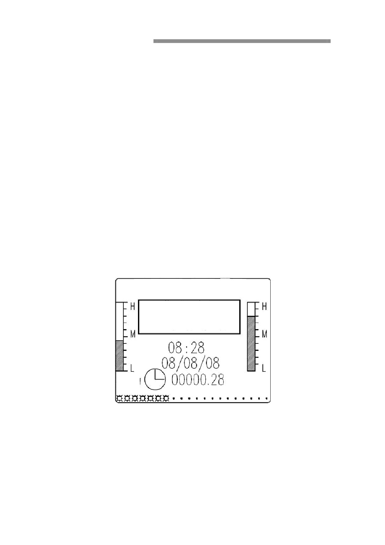
When the machine is operating normally, the monitor will display the following: (main frame)
SHANTUI
Operating state
Waiting to start
Fuel
Coolant
temperature
They can be divided into 6 areas:
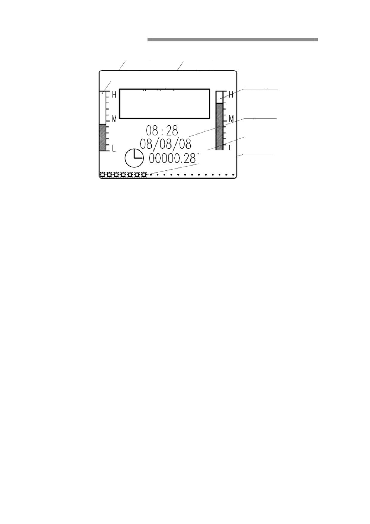
Fuel level display
Operating state display
Coolant temperature
SHANTUI
display
Operating state
Waiting to start
Clock/calendar
disaplay
Time and date
Set speed display
Coolant
Fuel
temperature
Expressed as follows:
1. Status display area
Displays the current engine operating state, such as the [start waiting] , [waiting for
operations], [normal operation], [delay] and so on standby.
Monitoring system monitors the situation of engine lubrication system, cooling
system, intake system, power generation systems, and hydraulic system at the same
time.
If the system gets problem, it will display the following fault alarm information in
the status area:
Level 1 alarms
1.1. It displays [Coolant level] and flashes to indicate that the engine coolant level is below the
normal value. At the same time, the buzzer sounds.
1.2. It displays [Coolant temperature too high] and flashes to indicate that the engine coolant
temperature is above the normal value. At the same time, the buzzer sounds.
1.3. It displays [Oil lubrication] and flashes to indicate that the engine oil pressure is below the
normal value. At the same time, the buzzer sounds.
1.4. It displays [System pressure] and flashes to indicate that the line pressure of the hydraulic
system is above the normal set value. At the same time, the buzzer sounds.
1.5. It displays [Voltage too low] and flashes to indicate that the battery voltage is below 22V.
At the same time, the buzzer sounds.
1.6. It displays [Voltage too high] and flashes to indicate that the battery voltage is above 32V.
At the same time, the buzzer sounds.
1.7. It displays [Speed sensing] and flashes to indicate speed sensor signal abnormality. At the
same time, the buzzer sounds.
Level 2 alarms:
1.8.
It displays [Please refuel] and flashes to indicate that the remaining fuel in the fuel tank is

inadequate and that refueling is needed.
1.9. It displays [Air cleaner dirty] and flashes to indicate that the air cleaner is dirty and that
you need to clean up or replace the intake filter screen.
2. Fuel display area
An analog bar is used to display percentage of fuel in the fuel tank. When fuel level is below 20%,
it will display a “
” in the Time & Date position and flashes; at the same time, the status
display area will display a prompt [Please refuel].
3. Coolant temperature display area
An analog bar is used to display engine coolant temperature (℃). When the temperature is above
100℃, it will display a “
” in the Time & Date position and flashes; at the same time, the
status display area will display a prompt [Coolant temperature too high] and the buzzer will sound.
4. Calendar and clock display area
4.1. This area displays current date and time.
4.2. In case of malfunction alarm, an alarm prompt will be displayed in this position. (Alarm
messages are highlighted.)
4.2.1. It displays
and flashes to indicate too low engine coolant level.
4.2.2. It displays
and flashes to indicate too high engine coolant temperature.
4.2.3. It displays
and flashes to indicate too low engine oil pressure.
4.2.4. It displays
and flashes to indicate too high line pressure in the hydraulic system.
4.2.5. It displays
and flashes to indicate inadequate remaining fuel.
4.2.6. It displays
and flashes to indicate abnormal battery voltage.
4.2.7. It displays
and flashes to indicate dirty air cleaner.
4.2.8. It displays
and flashes to indicate abnormal speed sensor signal.
5. Hour meter
Then the engine start to timing meter start to working, the engine stop the timing meter will
stop too. Every time restart engine, the timing meter working base on the total time. The
picture will display the total time from the newest time.
6. Set speed display
Displaying the engine set speed of the current operating mode.
II. Description of key board
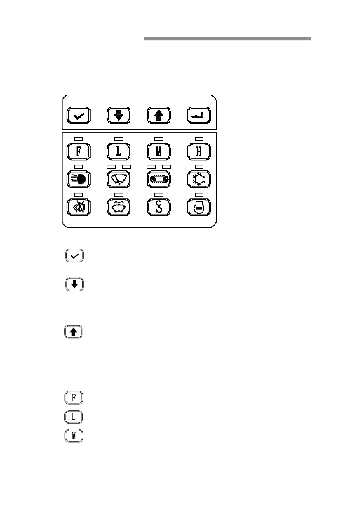
Monitor operating key board screen, as shown
Menu button
1.
is enter button, press this key to confirm that the contents of the prompt or
enter the options menu;
2.
is Page Down key, the contents of the key is corresponding to the
operation with the top of the screen.
In normal display mode, in addition to 【F】 mode, pressing this button can follow
50RPM / set times to reduce the engine speed.
3.
is Page Up key, the contents of the key is corresponding to the operation
with the top of the screen.
In normal display mode, in addition to 【F】 mode, pressing this button can follow
50RPM / set times to increase the engine speed.
Working Mode key
5.
is【F】 mode control keys; System is working in fine (slow) mode;
6.
is
【L】mode control keys; The system is working in Light-load mode;
7.
is
【M】mode control keys; The system is working in Standard operating
mode;
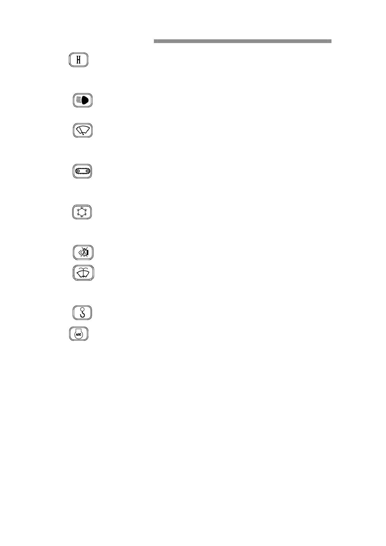
8.
is
【H】mode control keys; Strong power mode system.
Control key
9.
is working lights switch, press once to turn on the lights, and press again
will turn off the light.
10.
is brush key, press this key ,the L light will on means the brush in the
interval working situation , press again , the H lamp will light means brush in the
continue working situation, press the third time , the brush will stop working.
11.
is the double walk speed key , press this key , the above L lamp will light
means walking in the low speed, press again the H lamp light , means walking in
high speed situation. Press again the walking situation will back to low speed.
12.
is air conditioner key , press this key the refer lamp will light , means the
air conditioner have turn on
, when press again the lamp will off and the
air-conditioner will not working .
13.
is mute control buttons, press this key to keep the buzzer silent;
14.
is the brush water spray key, press this key, the lamp will light, the spray
pump will out of water, same time the brush will working. Leave this key the lamp
will off, and spray stopping and the brush stop too.
15.
(Optional) is Micro-mode control keys;
16.
is idle speed key, the lamp light time the situation are automatic to come back idle
speed and so operation leader, the engine automatic to back default speed to working , operation
leader in middle position stop more than 1 second, and start to delay, delay 7 seconds , the engine
automatic back to idle speed. The lamp off and the working will be manual work, now engine are
working on the default situation.
III.
Operating instructions
Make sure the safety lock lever is in the locked (raised up) position.
1.
After the start key is turned ON, the system will perform self check and initialization first. After
finishing initialization, the system will enter the main working interface automatically. If no
alarm signal appears on the display screen, the status display area should show [Waiting to start].
2. Turn the start key clockwise to the START position to start the engine. After the engine is started,
release the key rapidly to allow the engine to run automatically in idle state. Then the status
display area will show [Waiting to operate].
3.
Select operating mode according to operational need. (At engine start, the default mode is
[F].)
[H] mode: maximum power output. It is suitable for heavy-load operation.

[M] mode: 90% power output. It is suitable for operation in standard condition.
[L] mode: 70% power output. It is suitable for light-load operation.
[F] mode: 30% power output. It is suitable for occasions where fine movements are
required.
Generally [M] mode is recommended because it can significantly improve working condition,
reduce fuel consumption, noise, temperature rise and wear, and prolong life of the engine. In
auto idle state, set down the safety lock lever and operate the left and right levers or the travel
lever, then the engine will automatically run in the selected operating mode and the status
display bar will show [Running normally].
4.
To change engine speed in the operation process, you can press
or
key to
decrease or increase the working speed of the engine. Each press can rev down (up) the
engine by 50prm. The speed adjustment is valid only in this on/off period. At restart after
the system is turned off, the engine will return to the default set speed.
5.
Once an alarm signal, such as [Oil lubrication], [Coolant level] or [Coolant temperature too
high] message, appears in the status display area, stop immediate and check (refer to latter
fault handling section for details). Otherwise, the system will rev down the engine to idle
speed and record down time after 1 minute automatically. No record will be kept when
the engine is out of operation.
6.
After finishing work, do not turn off the engine immediately. Instead, let the engine rev
down to idle speed automatically and run 3-5 minutes before shutdown, otherwise the
service life of the engine will be affected.
CAUTION: All keys are touch keys (each press corresponds to an operation) except that
the wiper spray key must be pressed and held to complete an operation.
IV. Fault handling and troubleshooting
In addition to displaying operating states, the monitor can also supervise operating states of the
lubrication system, cooling system, intake system, and generator system of the engine. If any of
above systems is out of order, the following prompts will appear in the Time & Date position on
the screen respectively:
Level 1 alarms
1.
[Oil lubrication] prompt: low pressure in lubrication system. Troubleshooting should
be carried out mainly in the following 3 aspects.
Check engine oil line for clogging.
Check engine oil pump for proper operation.
Check for lack of engine oil.
2.
[Coolant temperature too high] prompt: It indicates that coolant temperature is above
100℃. In case of coolant temperature alarm, check the cooling system immediately.
Check the water tank for too high actual temperature and heavy coolant leak.
3.
[Coolant level too low] prompt: It indicates that the coolant level in the radiator or
surge tank is below the safe value. Then a troubleshooting is required:
Check surge tank and water radiator for lack of coolant and seals of water radiator and

adapters for leakage.
Check if coolant level in surge tank is below LOW mark.
Check coolant level sensor which is mounted in two ways and falls into two types:
A. Mounted on water radiator: To check it in case of alarm, disconnect the sensor
connector and short it. If the alarm disappears, poor contact of the connector, sensor
bubbles or sensor damage may occur; if the alarm remains, perform troubleshooting
forward in turn to check for poor contact of connector.
B. Mounted on surge tank: To check it incase of alarm, disconnect the liquid level sensor
of the surge tank. If the alarm disappears, you need to replace the coolant level sensor;
if the alarm remains, perform troubleshooting forward in turn to observe signal wires
for short circuit.
4.
[System pressure] prompt: The pressure in the main pump of the hydraulic system is
above the set value.
·Check the constant pressure valve on the main valve for normal operation.
If none of above occurs, please contact the nearest agent for help.
CAUTION: Once such alarm signal is displayed, stop immediately and check. Otherwise,
the system will rev down the engine to idle speed and record down time after 1 minute
automatically.
Please see the figure below:
Failure time
Low oil alarm
Min
Low coolant alarm
Min
High temperature alarm
Min
Clear record Options
Back
Level 2 alarms:
5.
[Voltage too low] prompt: It indicates that the battery voltage is below 22V. Then
you should try to start the engine once and judge the fault according to the response:
If the engine can start and the alarm will disappear after the former has run for 10
minutes, then minor power loss occurs. You can troubleshoot the problem by running
the engine for an extended period of time. You can troubleshoot the problem by
running the engine for an extended period of time.
If the engine can start but the alarm remains after the former has run for 10 minutes,
then you should check the generator for normal power generation and the battery for
damage.
If the engine can not start, then serious battery power loss occurs or the battery has
been damaged and you should service or replace the battery.
6.
[Vol tage too high] prompt: It indicates that the battery voltage is above 32V. When

the engine is running properly, its working voltage should be 26V-31V. At this point, you
should measure the actual voltage of the battery.
·If the voltage is greater than 31.5V when the engine is running properly, then the
generator regulator is out of order and you should service or replace the generator.
7.
[Air cleaner dirty] prompt: It indicates that the air cleaner element is dirty. Then you
should clean up or replace the element.
8.
[Please refuel] prompt: It indicates that the actual fuel level in the fuel tank is less than
20%. Then you should check fuel level in the fuel tank and refuel in a timely manner.
9.
[Speed sensing] prompt: It indicates that no speed signal comes from the speed sensor
on the flywheel housing of the engine. Then you should check the engine speed sensor and
corresponding lines.
Other operations
After entering the main interface, you can press [OK] key to open System Setup and Log frame:
System Setup and Log options
01 Troubleshooting
02 Speed and Power
03 Time Setting
04 Failure Logging
05 System Help
Clear Record
Options
Back
After entering the main interface, you can press [OK] key to open System Setup and Log frame:
General settings include Troubleshooting, Time Setting, and System Help. Speed and Power
Settings, Working Hourmeter Setting, and Failure Logging are advanced settings which will not
be described here. (Only service personnel of or persons authorized by the company have access
to advanced settings.)
1. Troubleshooting
Press Page Up/Down key to move the black box in the figure up/down, and select “01”. Then
press [OK] key to open Troubleshooting frame.
Circuit Fault Display
Temperature Sensor Circuit
Fuel Sensor Circuit
Speed Sensor Circuit
Troubleshooting
Back
a.
The displayed statuses of the temperature sensing circuit are divided into [Normal], [Open
Circuit/Low Temperature], and [Short Circuit].
b. The displayed statuses of the fuel sensing circuit are divided into [Normal], [Open Circuit], and
[Short Circuit].
c.
The displayed statuses of the speed sensing circuit are divided into [Normal] and [No Signal].
If selecting Troubleshooting, then you will enter the frame
shown right:
Troubleshooting Flow
01 Check a switch for control failure
02 Troubleshoot a power regulation
failure
03 Check for throttle circuit fault
OK Options Options Back
Press Options key to select and [OK] key to enter the items of next level. You can troubleshoot a
problem step by step by screen.
2. Clock display and adjustment
In System Setup and Log frame, press Page Up/Down key to select “03” and press [OK] key in
succession to open [Clock Adjustment] frame. Date and Time on display screen of the monitor
can be set respectively.
Clock Time Setting
Year Month Day Hour Minute
Options Adjustment- Adjustment+ Back
In above figure, you can cycle among Year, Month, Day, Hour and Minute by pressing
corresponding keys of the options. When an option is selected, you can adjust the corresponding
item using Adjustment keys.
After Year is selected, you can adjust it within 00-99 by using [Adjustment+] /
[Adjustment-].
After Month is selected, you can adjust it within 01-12 by using [Adjustment+] /
[Adjustment-].
After Day is selected, you can adjust it within 01-31 by using [Adjustment+] /
[Adjustment-].
After Minute is selected, you can adjust it within 00-59 by using [Adjustment+] /
[Adjustment-].
Press [Esc] key to exit the frame.
3. Maintenance time records (optional)
In System Setup and Log frame, press Page Up/Down key to select “05” and then press [OK] to
enter [Maintenance Records] frame where can display schedule of periodic maintenance and
prompt customers to perform maintenance periodically.
The frame displays the specific time records of the 3 free maintenance services carried out by the
manufacturer for the vehicle delivered:
500h, 1,000h, and 2,000h
1.
The first engine maintenance should be carried out at 500 working hours as of the date of
delivery. Now xxx hours left until the 500h maintenance.
2.
The second engine maintenance should be carried out at 1,000 working hours as of the date
of delivery. Now xxx hours left until the 1,000h maintenance.
3.
The third engine maintenance should be carried out at 2,000 working hours as of the date of
delivery. Now xxx hours is left until the 2,000h maintenance.
After each maintenance service is completed, the system will display a “Maintenance
Finished” prompt
4. System Help
In System Setup and Log frame, press Options key to select “05” and then press [OK] to enter
the interface shown below.
System Help
01 System Status
02 Start and Stop
03 Lubrication and Maintenance
04 Engine Maintenance
05 Hydraulics and Circuits
06 Default Settings
OK
Options
Back
This setting can help customers solve some problems, troubleshoot malfunctions, and inquire
about current operating state of the machine.
When the machine is out of order, you should view system status first. Press [OK] key, and the
interface shown below will appear:
//////////////////////////////////////////