Technical Manual for Drilling Works for Technical Support Plan for the Drillers in DDCA (2013) - page 1
Drilling and Dam Construction Agency (DDCA)
Japan International Cooperation Agency (JICA)
DDCAP
Technical Manual for Drilling Works
for Technical Support Plan for the
Drillers in DDCA
Version 1
March 2013
Groundwater Development and Management Capacity Development (DDCAP)
Project
Contents
1 INTRODUCTION
1
2 DRILLING TOOLS AND EQUIPMENT (TA COde 2)
3
2.1
SELECTION OF DRILLING BIT AND DRILLING METHOD (TA CODE 2-1)
3
2.2
ROTARY BITS (TA CODE 2-2)
8
2.3
DTH AND DTH BIT (TA CODE 2-3)
9
2.4
RIG ACCESSORY (TA CODE 2-4)
11
2.5
CASING TOOLS (TA CODE 2-5)
17
2.6
DRILLING EQUIPMENT (TA CODE 2-6)
22
2.7
DRILLING CALCULATION (TA CODE 2-7)
26
2.8
WEIGHT OF DRILLING TOOLS (TA CODE 2-8)
37
2.9
ROTARY BIT ROTATION SPEED AND WEGHT ON BIT (TA CODE 2-9)
39
2.10
DTH BIT ROTATION SPEED AND WEGHT ON BIT (TA CODE 2-10)
41
3 DRILLING CONTROL (TA Code 4)
42
3.1
MUD CONTROL (A CODE 4-1)
42
3.2
MUD PUMP OPERATION (TA CODE 4-2)
43
3.3 CASING FOR MUD DRILLING (TA CODE 4-3)
44
3.4 DRILLING OPERATION FOR MUD DRILLING (TA CODE 4-4)
45
3.5 BIT CONTROL AND REPARING FOR MUD DRILLING (TA CODE 4-5)
48
3.6 AIR CONTROL FOR DTH DRILLING (TA CODE 4-6)
49
3.7 AIR COMPRESSOR OPERATION (TA CODE 4-7)
50
3.8 CASING FOR DTH DRILLING (TA CODE 4-8)
51
3.9 DRILLING OPERATION FOR DTH DRILLING (TA CODE 4-9)
52
3.10 BIT CONTROL AND REPARING FOR DTH DRILLING (TA CODE 4-10)
53
4 BOREHOLE LOGGING (TA CODE 5)
54
4.1 BOEREHOLE LOGGING INSTRUMENTS (TA CODE 5-1)
54
4.2 INTERPRETATION OF BOREHOLE LOGGING RESULTS (TA CODE 5-2)
60
5 GRAVEL PACKING (TA COde 7)
65
5.1 DETERMINATION OF GRAVEL SIZE (TA CODE 7-1)
65
5.2
CALCULATION OF GRAVEL VOLUME (TA CODE 7-2)
67
5.3 GRAVEL PACKING (TA CODE 7-3)
68
6 WELL DEVELOPMENT (TA CODE 8)
70
6.1
WELL CLEANING AFTER DRILLING (TA CODE 8-1)
70
6.2
SINGLE TUBE METHOD AIR LIFTING (TA CODE 8-2)
72
6.3
DOUBLE-TUBE METHOD AIR LIFTING (TA CODE 8-3)
73
7 BACK-FILLING&SURFACE CEMENTING (TA CODE 9)
74
7.1
BACK-FILLING (TA CODE 9-1)
74
7.2 SURFACE CEMENTING (TA CODE 9-2)
77
2. Slurry poured into the borehole
78
8 PUMPING TEST (TA CODE 14)
79
8.1 PURPOSE AND METHODS OF PUMPING TEST (TA CODE 14-1)
79
8.2 PUMPING TEST EQUIPMENT (TA CODE 14-2)
81
8.3 SELECTION OF SUBMERSIBLE PUMP (TA CODE 14-3)
83
8.4
INTERPRETATION OF TEST RESULTS (TA CODE 14-4)
88
9 WATER QUALITY (TA CODE 15)
95
9.1 PURPOSE OF WATER QUALITY ANALYSIS (TA CODE 15-1)
95
9.2 ITEM OF WATER QUALITY ANALYIS (TA CODE 15-2)
97
Tables
Table 1 Identified Technical Areas Covering Drilling Works of DDCA
1
Table 2 Technical Area / Item Covered by Teaching Guidance and Manuals
1
Table 3 Drilling Performance of Drilling Methods for Type of Formation
6
Table 4 Selection of Bit for Rotary Cum DTH Drilling
7
Table 5 Connection of Rotary Bit
8
Table 6 Rig Accessories DDCA’s New Drilling Rig of 150 m Capacity
11
Table 7 Capacity of API Drill Pipe
14
Table 8 Capacity of API Drill Collar
15
Table 9 Identification of API Threads
16
Table 10 Size of API 5L-B Steel Pipes
17
Table 11 Size of JIS STPG Sch-40 Steel Pipes
18
Table 12 Size of JIS SGP Steel Pipes
18
Table 13 Size of BS Heavy Steel Pipes
18
Table 14 Size of uPVC Pipes
21
Table 15 Specifications of NP-700 Mud Pump
24
Table 16 Conversion Factors - Imperial to Metric
27
Table 17 Conversion Tables - Length and Area
29
Table 18 Conversion Tables - Velocity and Flow
29
Table 19 Conversion Tables - Imperial Gallons to Litres
30
Table 20 Conversion Tables - Litres to Imperial Gallons
30
Table 21 Conversion Tables - Acre-Feet to 1,000 Cubit Meters
31
Table 22
Conversion Tables - Cubic Yards to Cubic Meters
32
Table 23
Conversion Tables - Imperial Gallons Per Minute to Litres Per Second
33
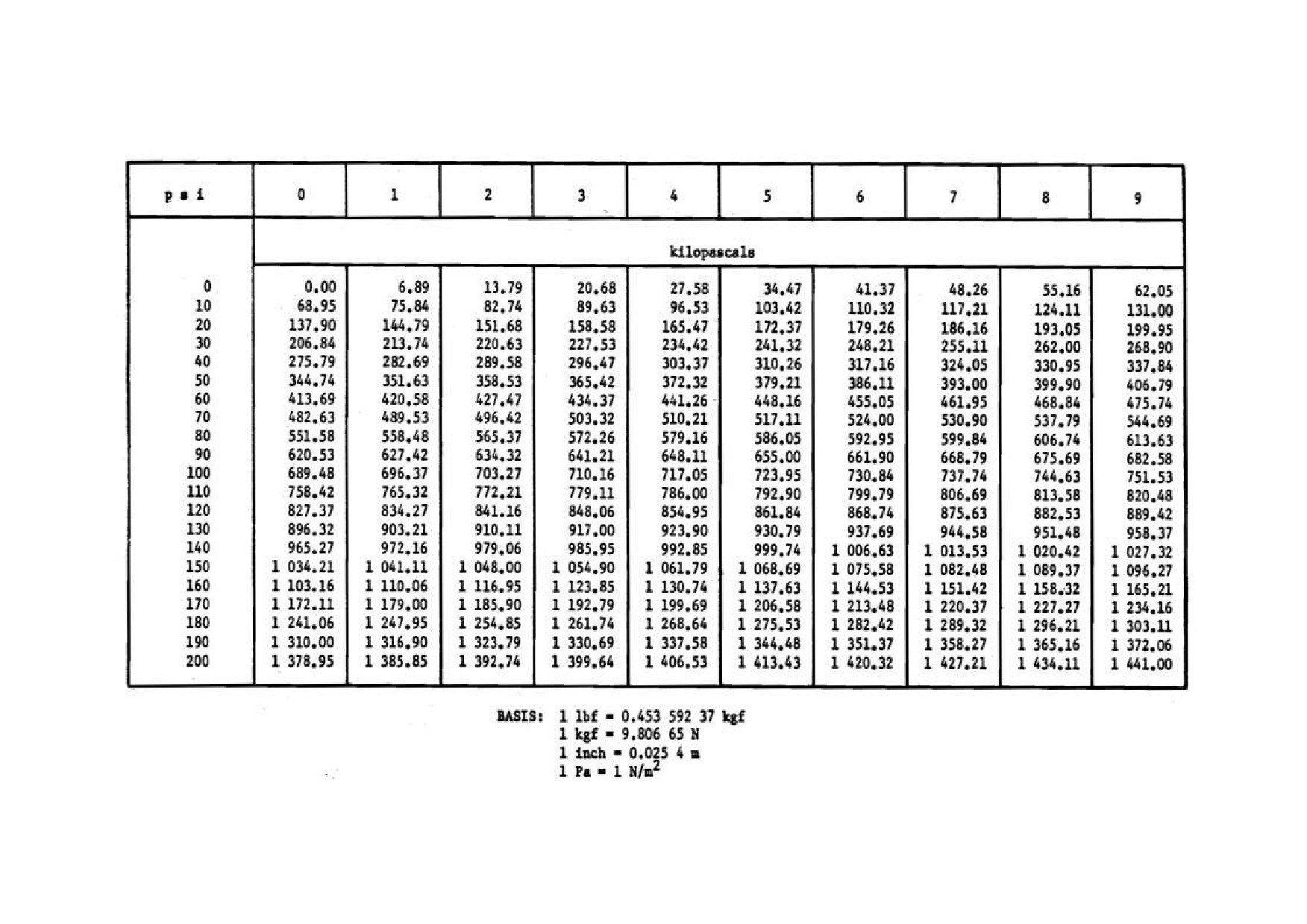
Table 24
Conversion Tables - Pounds Per Square Inch to Kilo Pascals
34
Table 25
Conversion Tables - Horsepower to Kilowatts
35
Table 26
List of Necessary Tools for 12-1/4” and 8-1/2” Drilling
37
Table 27
Drill String Assembly for 12-1/4” x 30 m Drilling
37
Table 28
Drill String Assembly for 8-1/2” x 100 m Drilling
37
Table 29
Weight Calculation of Drill String Assembly for 12-1/4” x 30 m Drilling
38
Table 30
Weight Calculation of Drill String Assembly for 8-1/2” x 100 m Drilling
38
Table 31
Example of Bit Log Sheet
48
Table 32
Example of DTH Log Sheet
53
Table 33
Example of Cement Mixing Calculation
77
Table 34
Conversion Table of Discharge Rate for 90 Deg. Notch Tank
82
Table 35
Specifications of Submersible Pump SP17 (Grundfos)
84
Table 36
Water Quality Parameters and each Pollition Sources and Effects
95
Table 37
Values of WHO Guideline and TTS
97
Table 38
Frequency of Sampling for Rural Water Supply
98
Table 39
Frequency of Sampling for Urban Water Supply
98
Figures
Figure 1 Mechanism of DTH Drilling Method
4
Figure 2 Mechanism of Mud Rotary Drilling Method
5
Figure 3 Structure of Cable and Tool Drilling Machine
5
Figure 4 Structure of Tri-cone Tooth Bit
8
Figure 5 Structure of DTH
9
Figure 6 Structure of DTH Bits
9
Figure 7 Standard Drill Sttring Assembly
13
Figure 8 Specifications of Steel Casings and Drill Bits
20
Figure 9 Casing Lifting Tools
21
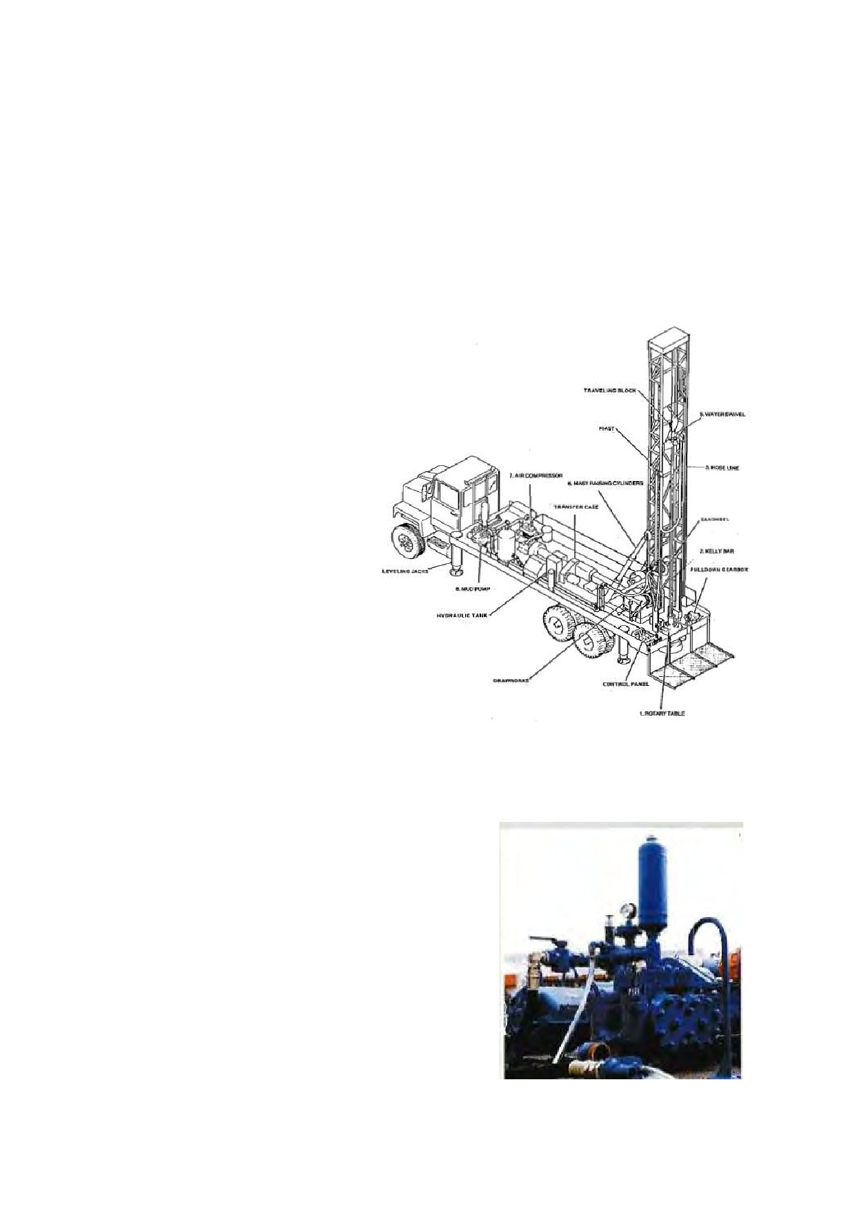
Figure 10 Structure of Truck-mounted Drilling Rig
22
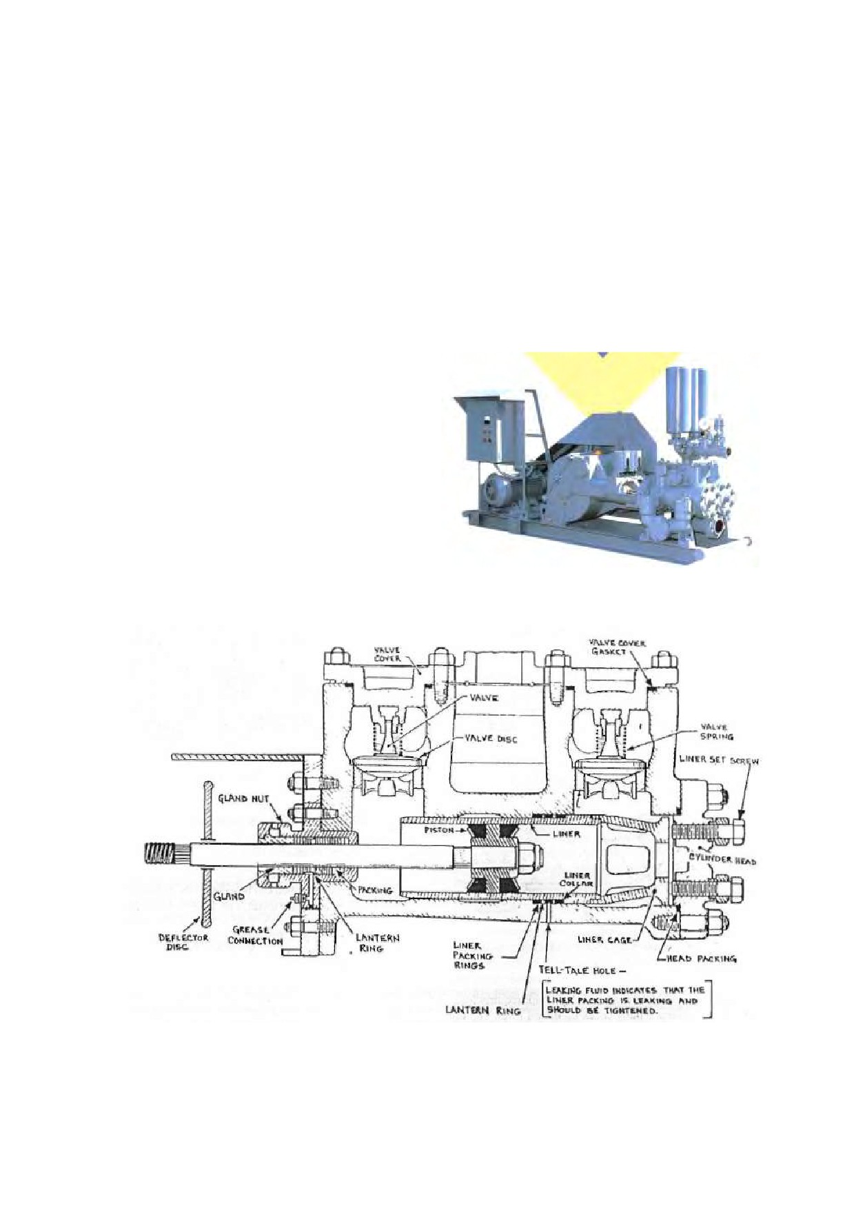
Figure 11 Structure of Mud Pump
22
Figure 12 Duplex Mud Pump NP-700 (TONE)
23
Figure 13 Internal Structure of Mud Pump
23
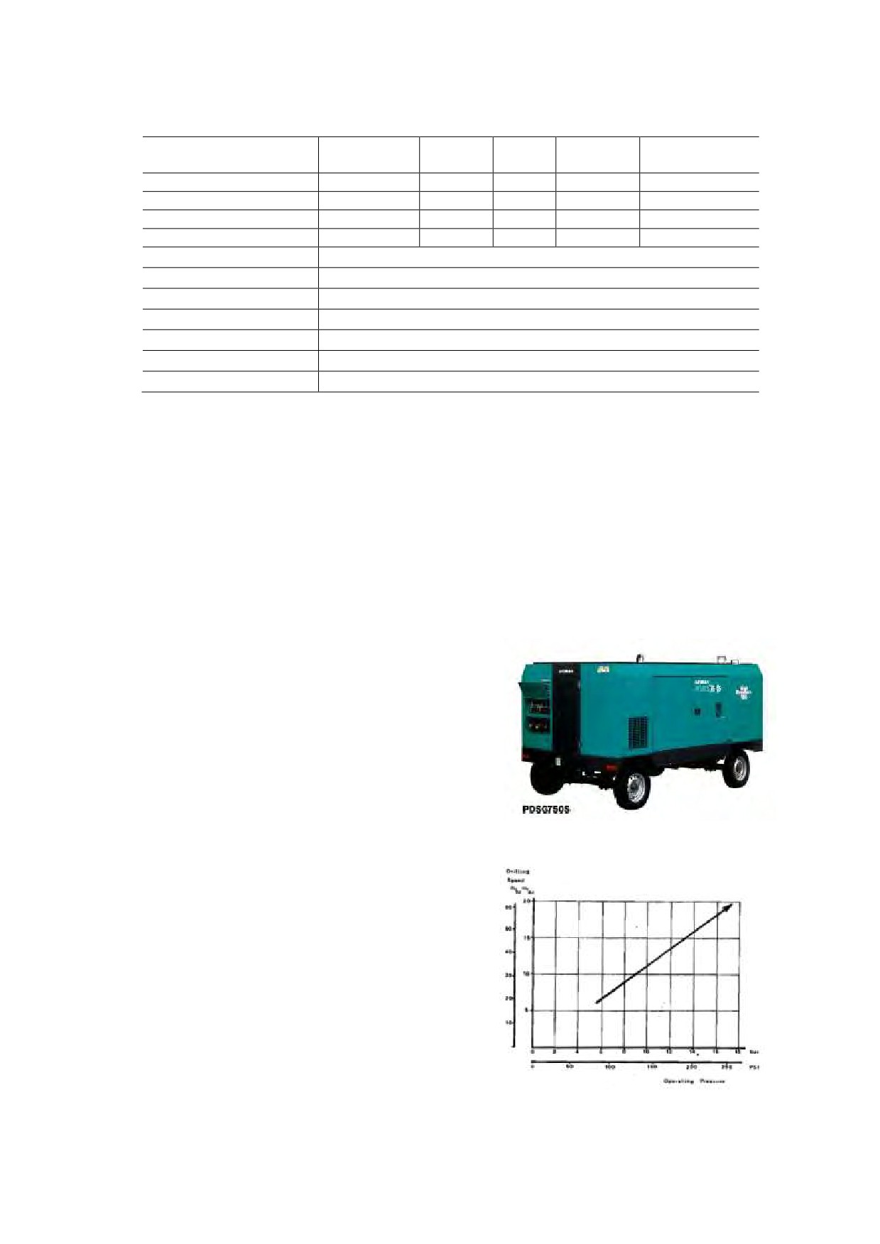
Figure 14 Rotary Screw Air-Compressor PDSJ750S (21 m3/h, 21 bar)
24
Figure 15 Change of Drilling Speed by Operating Pressure of DTH
24
Figure 16
DDCA’s New Cargo Truck
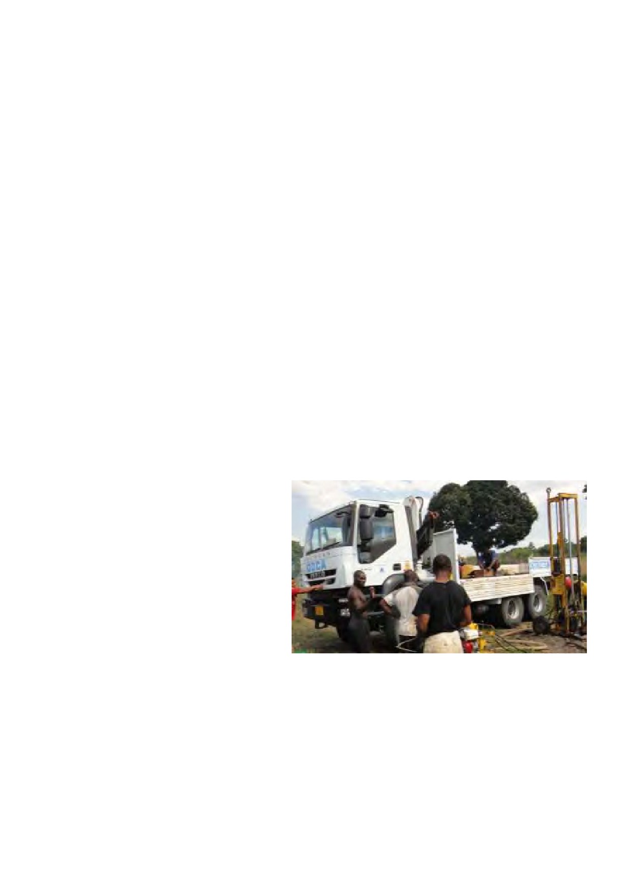
25
Figure 17
Bit Penetration and Rotary Speed
39
Figure 18
Example of the Calculation of WOB
39
Figure 19
Standard Layout of Drilling Equipment on Site
42
Figure 20
Work Flow of Mud Drilling
45
Figure 21
DDCA’s Well Completion Form
46
Figure 22
DDCA’s Well Section Drawing Form
47
Figure 23
Example of the Casing Program for DTH Drilling Borehole
51
Figure 24
Work Flow of DTH Drilling
52
Figure 25
Work Procedure of Borehole Logging (Geologer 3030)
59
Figure 26
Example of Logging Result and Casing Program (Sedimentary Formation)
63
Figure 27
Example of Logging Result and Casing Program (Hard Rock Formation)
64
Figure 28
Example of Gravel Pack Design
65
Figure 29
Example of Sieve Analysis Sheet
66
Figure 30
Example of the Gravel Calculation
67
Figure 31
Installation of Gravel Pack
68
Figure 32
Measurement of Gravel Top
68
Figure 33
Installation of clay pellets
68
Figure 34
Development by Single-Tube Air-Lifting
70
Figure 35
Single Tube Air-Lifting Method
72
Figure 36
Double-Tube Air-Lifting Method
73
Figure 37 Government Specifications and Regulations Applicable to Water Well Drilling and
Installation Method
74
Figure 38 Work Procedure of Surface Cementing
78
Figure 39 Example of Results of Step Drawdown Tests (t-dwl curve)
79
Figure 40 Example of Results of Step Drawdown Tests (Q-s curve)
79
Figure 41 Example of Results of Step Drawdown Tests and Recovery Test (t-s curve)
80
Figure 42 Standard Setting of Pumping Test Instruments
81
Figure 43 Structure of Notch Tank
81
Figure 44 Example of Calculation of Pump Total Head (Discharge Rate 10 m3/h)
85
Figure 45 Pressure Loss Nomogram for Galvanized Steel Pipe
86
Figure 46 Pump Capacity Curve of SP17 Serieis (GRUNDFOS)
87
Figure 47 Example of Form of Summary of Pumping Test
88
Figure 48 DDCA’s Record Form of Constant Discharge Rate Test
89
Figure 49 DDCA’s Record Form of Recovery Test
90
Figure 50 Example of Results of Step Drawdown Test
92
Figure 51 DDCA’s Record Form of Recovery Test
92
Figure 52 Example of Interpretation of Step Drawdown Test
93
Figure 53 Summary Report of Pumping Test Result and Pump Installation Plan
94
DDCAP Technical Manual for Drilling Works
For Technical Support Plan for the Drillers in DDCA
1 INTRODUCTION
The baseline survey on DDCA’s drilling organization was conducted in the course of the Project,
for the purpose to reveal the current status of drilling works and the technical level of drillers in
DDCA. The results of the baseline survey were compiled in the Technical Support Plan for the
Drillers in DDCA (hereinafter referred to as “TSP”) which was formulated in January 2013. This
plan identified
15 technical areas which cover the drilling works of DDCA including eight
technical areas necessary to be enhanced and two new technical areas to be needed, as shown in
Table 1.
Table 1 Identified Technical Areas Covering Drilling Works of DDCA
New Areas
Areas to be
No.
Technical Area
All Areas
to be
Enhanced
Needed
1
Site Mobilization
✔
2
Drilling Tools and Equipment
✔
✔
3
Drilling Drawbacks
✔
4
Drilling Control
✔
✔
5
Borehole Logging
✔
✔
6
Casing Program / Installation
✔
7
Gravel Packing
✔
✔
8
Well Development
✔
✔
9
Back-Filling & Surface Cementing
✔
✔
10
Site Demobilization
✔
11
Well Investigation
✔
12
✔
13
✔
14
✔
15 Water Quality Analysis
✔
This Technical Manual for Drilling Works was prepared according the TSP and covers eight
technical areas to be enhanced. This manual is expected to be utilized by the senior drillrs in
DDCA in order to acquire the necessary technical knowledge and the proper work procedures.
Furthermore, it forms a part of materials for the teaching guidance which is used for the technical
instruction to both private drillers and DDCA’s drillers. In the TSP, the technical areas were
further divided into details namely technical items. Technical areas and items are the important
basic units for the activities of technical training and guidance in the Project, in the respects of the
manual formulation, training plan, technical evaluation and so on. They are commonly used
between three major training related documents i.e. the Teaching Guidance, the Manual for Drilling
Works and the Manual for Well Rehabilitation and Tool Fishing, as shown in Table 2.
Table 2 Technical Area / Item Covered by Teaching Guidance and Manuals
Manual for Well
Teaching
Manual for
TA Code
Technical Area / Item
Rehabilitation and
Guidance
Drilling Works
Tool Fishing
1
Site Mobilization
✔
1-1
Site Preparation and Drilling Machine Setting-Out
✔
2
Drilling Tools and Equipment
✔
✔
2-1
Selection of drilling bit and drilling method
✔
✔
2-2
Rotary Bits
✔
✔
2-3
DTH and DTH Bit
✔
✔
2-4
Rig Accessory
✔
✔
2-5
Casing Tools
✔
✔
2-6
Drilling Equipment
✔
✔
2-7
Drilling Calculation
✔
✔
2-8
Weight of drilling tools
✔
✔
2-9
Rotary bit rotation speed and weight on bit
✔
✔
2-10
DTH Bit rotation speed and weight on bit
✔
✔
1
DDCAP Technical Manual for Drilling Works
For Technical Support Plan for the Drillers in DDCA
Manual for Well
Teaching
Manual for
TA Code
Technical Area / Item
Rehabilitation and
Guidance
Drilling Works
Tool Fishing
3
Drilling Drawbacks
✔
3-1
Countermeasures against lost circulation during mud
✔
drilling
3-2
Countermeasures against lost circulation during DTH
✔
drilling
3-3
Countermeasures against bore wall collapse during mud
✔
drilling
3-4
Countermeasures against bore wall collapse during DTH
✔
drilling
3-5
Countermeasures against jamming of drilling tools
✔
4
Drilling Control
✔
✔
4-1
Mud control
✔
✔
4-2
Mud Pump Operation
✔
✔
4-3
Casing for mud drilling
✔
✔
4-4
Drilling operation for mud drilling
✔
✔
4-5
Bit control and repairing for mud drilling
✔
✔
4-6
Air control for DTH drilling
✔
✔
4-7
Air compressor operation
✔
✔
4-8
Casing for DTH drilling
✔
✔
4-9
Drilling operation for DTH drilling
✔
✔
4-10
Bit control and repairing for DTH drilling
✔
✔
5
Borehole Logging
✔
✔
5-1
Borehole logging instruments
✔
✔
5-2
Interpretation of borehole logging results
✔
✔
6
Casing Program / Installation
✔
6-1
PVC casing, screen pipe
✔
6-2
Casing Program
✔
6-3
Role of centralizer
✔
6-4
Casing, screen pipe installation
✔
7
Gravel Packing
✔
✔
7-1
Determination of gravel size
✔
✔
7-2
Calculation of gravel volume
✔
✔
7-3
Gravel packing
✔
✔
8
Well Development
✔
✔
8-1
Well cleaning after drilling
✔
✔
8-2
Single-tube method air-lifting
✔
✔
8-3
Double-tube method air-lifting
✔
✔
9
Back-Filling & Surface Cementing
✔
✔
9-1
Back-filling
✔
✔
9-2
Surface cementing
✔
✔
10
Site Demobilization
✔
10-1
Precautions upon site demobilization
✔
11
Well Investigation
✔
11-1
Necessary information of well rehabilitation plan
✔
11-2
Well rehibilitation plan
✔
12
Tool Fishing
✔
✔
12-1
Tool fishing plan
✔
✔
12-2
Fishing tools
✔
✔
13
Well Rehabilitatation
✔
✔
13-1
Phenomenan and causes of well deterioration
✔
✔
13-2
Methods of well rehabilitation
✔
✔
13-3
Usage of well camera
✔
✔
14
Pumping Test
✔
✔
14-1
Purpose and methods of Pumping Test
✔
✔
14-2
Pumping test equipment
✔
✔
14-3
Selection of Submersible Pump
✔
✔
14-4
Interpretation of test results
✔
✔
15
Water Quality Analysis
✔
✔
15-1
Purpose of Water quality analysis
✔
✔
15-2
Item of water quality analysis
✔
✔
2
DDCAP Technical Manual for Drilling Works
For Technical Support Plan for the Drillers in DDCA
2 DRILLING TOOLS AND EQUIPMENT (TA CODE 2)
2.1 SELECTION OF DRILLING BIT AND DRILLING METHOD (TA CODE 2-1)
2.1.1 PRICIPLES OF DTH, MUD AND CABLE AND TOOL DRILLING
(1) Types of Drilling Rig
Hydrogeology/ Drilling as an option has a major activities namely as;
1. Prospecting for groundwater
2. Drilling and well construction
Prospecting for groundwater deals with the investigation of groundwater existing at certain areas.
The aim of this task is to allocate well sites to produce water for human consumption. But a
geologist after this prediction is yet to prove weather his work is successful unless the water is
exploited.
The task of exploitation is given to the drillers. The driller sinks the well through the earth to
strike water from underground and takes it out to the surface to accomplish the task of drilling and
well construction. This work is done by the aid of drilling machine called a rig.
What is a Rig
A rig is a device , which is used to penetrate through the earth to a certain depth underground to
exploit minerals for human consumption.
Types of Rigs
1. Cable and tool percussive drilling (percussion )
2. Rotary drill rig
(schramn, xu 600 , pilcon, Romanian, Diamond)
3. Percussive rotary drill rig (schramn, aquadrll etc )
4. Core rotary drill rigs(, xu 600, pilcon, diamond)
5. Reverse circulation rotary drill rigs (Romanian)
EXPLANATION OF DRILLING RIGS
a. Rotary Rigs ;
This type of rig is designed to drill by applying rotation to the drilling
head driven by hydraulic oil pressure, which eventually drives the drilling string to
rotate . Bits like roller , alloyed bit and short bits are used.
b. Percussive Rotary Rigs;
In this type of rig the rotation application is quite the
same , except that the bit is connected
c. Cable and tool Percussive Rig;
This type of drilling method is accomplished by
regular lifting and dropping of a strings of tools. This phenomenon is aided by means of
connecting rod crank mechanism of oscillating movement to the locker frame. The
rocker frame ,the drum with a rope, which has the connection to the pulley and drilling
string.
d. Core Rotary Rigs ;
In this type of rig the drilling method is to drill and take out
cores instead of rocks dust ( rock cuttings ) Hollow bit and core barrel are used drilling
tools
e. Reverse Circulation Method;
In this method of drilling, setting of the circulation
system is reversible, that means the fluid flows hydraulically in the well, and then the
cuttings are uplifted inside the drill pipe up to the swivel where the sucktion hose is
connected to let out cuttings to the pump which eventually pumps the cuttings out to the
mud pit.
3
DDCAP Technical Manual for Drilling Works
For Technical Support Plan for the Drillers in DDCA
(2) Drilling Methods
There are various drilling methods, because of geological conditions range from completely
unconsolidated sediments such as alluvial sand and gravel to hard rock such as basalt and granite.
It is obviously then , that no single drilling methods is best for all geological conditions and well
installations successfully drilling in both , an art developed from long experience and application of
good engineering practices.
Well construction usually comprises five distinct operations
a. Drilling operations
b. Installing the casing
c. Placing a screen and filter pack
d. Developing well to ensure sand free operation at maximum yield(pumping test
)
e. Well completion
The term well drilling method is being used here to include all methods used in creating holes in
the era and for well construction purposes. It includes methods like boring and driving which are
not drilling methods in a pure sense.
Three drilling methods which are employed in DDCA are 1) DTH drilling method, 2) Mud rotary
drilling method and 3) Cable and tool drilling method. Mud rotary drilling methods and Cable
and tool drilling method are regarded as the types of Mud drilling methods. Cable and tool
drilling rigs are used for cable and tool drilling method, while rotary cum drilling rigs are used for
both Mud rotary drilling method and DTH drilling method. In this manual, drilling techniques of
DTH drilling and Mud rotary drilling are described as the drilling equipment to be hired to the
private drilling companies are of the type of DTH cum rotary. Principles of each drilling methods
are described below.
1) DTH Drilling Method
The (DTH) down the hole hammer
② Mud is injected
is rotary percussive tool, which
into the well by
the mud pump though
① Mud is vacuumed from the mud
operates at the bottom of the end of
the drill pipe.
pit to the mud pump
the hole being drilled. It is attached
mud pump
at the end of the drill string and
powered by compressed air flowing
truck-mouted
down the center of the drill string
rig
mud pit
into the hammer. The air operates a
piston within the hammer, which
④ Mud is pumpred to the mud
strikes the rear end of the drill bit
pit. Drill cutting settle down
drill
providing a percussive action. The
drilled
in the mud pit.
pipe
pneumatic drill can be used on any
hole
standard rotary rig with an air
③ Upward mud flow from the
drilling
compressor of sufficient capacity.
bit trasnports drill
bit
cutting.
It is used for fast and economical
Figure 1 Mechanism of DTH Drilling Method
drilling of medium to extremely
hard formation. Fast penetration
results from the air piston blows
are transmitted directly to the bit without losing energy through the string. Figure 1 show the
mechanism of DTH drilling method.
Performance varies with different makes of DHH but as an example a particular hammer
provided with 8 BARS (116Psi) air pressure will deliver 15.5 blows per second at the piston
striking the bit and with 14 BARS
(250Psi) air pressure will deliver 23 blows per second.
In water well drilling particularly air pressure must also overcome ground water pressure when
encountered. When drilling under the head of water, a back pressure is exerted against the air
pressure of the hammer and as the air pressure is less the back pressure approaches the minimum
4
DDCAP Technical Manual for Drilling Works
For Technical Support Plan for the Drillers in DDCA
operating pressure of the hammer penetration rates will gradually fall to zero, and in the fact the
hammer will cease to operate.
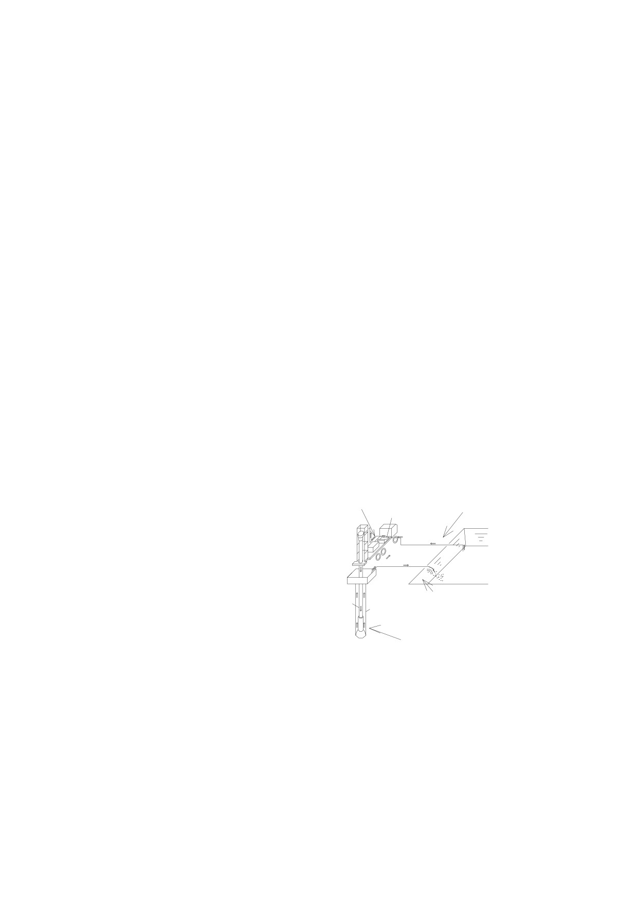
2) Mud Rotary Drilling Method
In this method, action is
② Mud is injected
accomplished by rotating a drill
into the well by
the mud pump though
① Mud is vacuumed from the mud
pipe by means of a power driven
the drill pipe.
pit to the mud pump
rotary table or top-head type
mud pump
swivel, with a bit cuts and breaks
up the material as it penetrates the
truck-mouted
formation. Drilling fluid for mud
rig
mud pit
is pumped through the rotating
drill pipe and through the hole
④ Mud is pumpred to the mud
picking up material broken by the
pit. Drill cutting settle down
drill
bit. Then flow upwards in the
in the mud pit.
pipe
drilled
space outside the drill pipe,
hole
carrying the cutting to the ground
③ Upward mud flow from the
drilling
surface, and clearing the hole.
bit trasnports drill
bit
The greater fluid flow the faster
cutting.
the drilling. The drill pipe and
Figure 2 Mechanism of Mud Rotary Drilling
bit move downward deepening the
Method
hole as the operation proceeds.
At the surface, drilling mud flows into a ditch to a settling pit where the cuttings settle to the
bottom. From the settling pit the fluid overflows into another pit from which it is picked up
through the suction hose of the mud pump and re-circulated through the drill pipe. In thr mud
rotary drilling method the casing pipe is not introduced until the drilling operations are
completed. The walls of the hole are held in place by the pressure of the mud against the sides
of the hole. Figure 2 shows the mechanism of mud rotary drilling method.
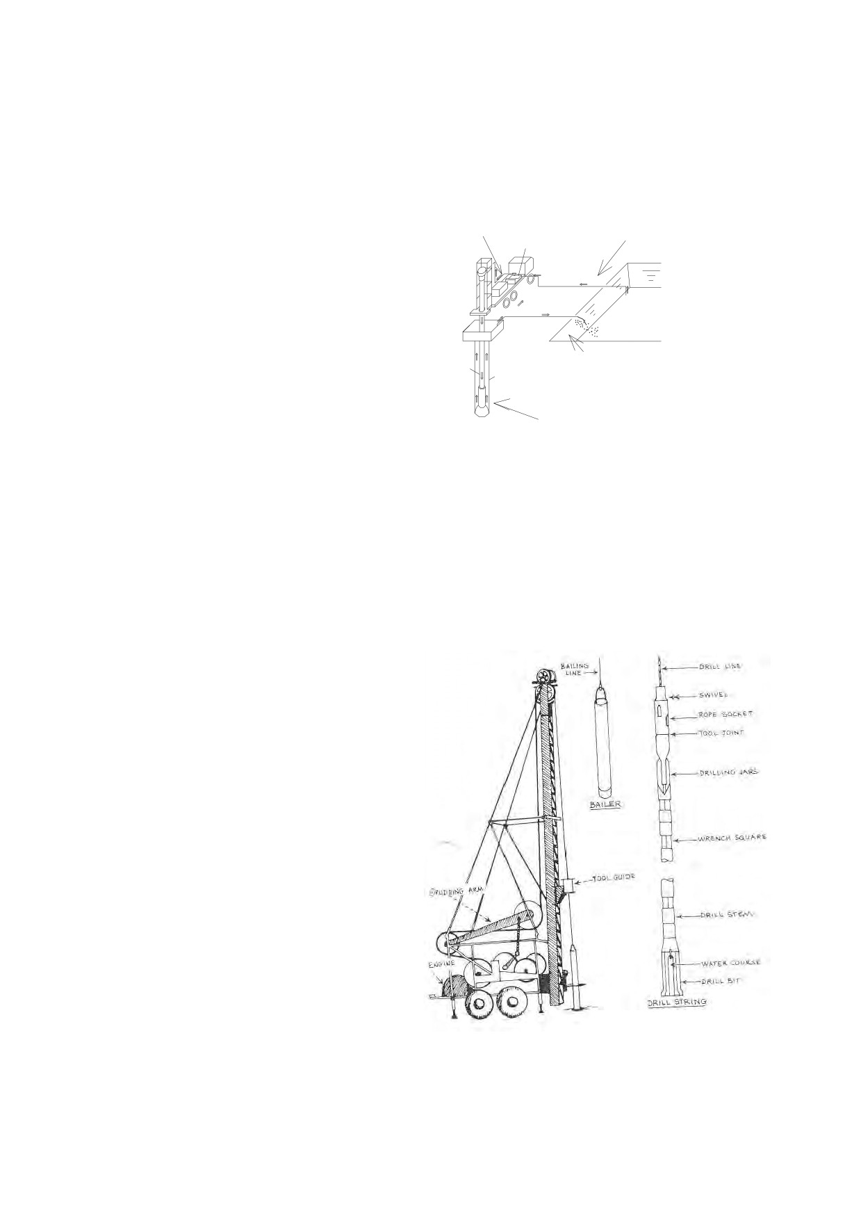
3) Cable Tool Method
The cable tool drills which drills by
means of lifting and dropping as many as
60 times a minute, a drill bit to break-up
and loose the material in well crushing
and breaking the formation material
The cable tool method has survived for
thousands of years because it is reliable
for a wide variety of geological conditions.
Figure 3
The tool method offer the following
advantages
1. Drilling are relatively inexpensive
2. Rig have low energy requirements
3. Rig are simple in design and
require
little
sophisticated
maintenance
4. Well are stabilized during the
entire operation
5. Taking samples is possible
from every depth
Figure 3 Structure of Cable and Tool Drilling
Machine
6. Well can be constructed with
little chance of contamination
7. Only 2 person are needed to operate rig
5

DDCAP Technical Manual for Drilling Works
For Technical Support Plan for the Drillers in DDCA
8. Well can be drilled in area where little water exist
9. Rig can be operated in all temperature regions
10. Well can be drilled in formation where loosen circulation is a problem
11. Well can be bailed at any time to determine the approximately field
DISADVNTAGES OF CABLE TOOL METHOD / METHOD ARE
1. Productive output measured in hole produced per day is low
2. In hard rock’s where penetration rate may be very low
3. When casing is required , deep drilling presents problems in keeping the casing free
4. The heavy hammering action causes disturbance and damage in same formation
2.1.2 SELECTION OF DRILLING METHODS AND BITS ACCORDING TO GEOLOGICAL CONDITIONS
A drilling method is to be selected principally based on their performance for types of geological
formations, as shown in Table 3.
Table 3 Drilling Performance of Drilling Methods for Type of Formation
Type of Formation
Cable and Tool
Mud Rotary
DTH
Dune sand
Difficult
Rapid
Not recommended
Loose sand and gravel
Difficult
Rapid
Not recommended
Quicksand
Difficult, except in thin
Rapid
Not recommended
streaks. Requires a string of
drive pipe.
Loose boulders in alluvial
Difficult - slow but
Difficult, Frequently
Not recommended
fans or glacial drift
generally can be handled by
impossible
driving pipe.
Clay and silt
Slow
Rapid
Not recommended
Firm shale
Rapid
Rapid
Not recommended
Sticky shale
Slow
Rapid
Not recommended
Brittle shale
Rapid
Rapid
Not recommended
Sandstone - poorly
Rapid
Rapid
Not recommended
cemented
Sandstone - well cemented
Fair
Slow
Not recommended
Chert nodules
Slow
Slow
Not recommended
Limestone
Slow
Rapid
Very Rapid
Limestone with chert
Very Slow
Slow
Very Rapid
nodules
Limestone with small
Very Slow
Slow
Very Rapid
cracks or fractures
Limestone cavernous
Very Slow
Slow to impossible
Difficult
Dolomite
Very Slow
Rapid
Very Rapid
Basalts, thin layers in
Slow
Slow
Very Rapid
sedimentary rocks
Basalts - thick layers
Slow
Slow
Rapid
Metamorphic rocks
Slow
Slow
Rapid
Granite
Slow
Slow
Rapid
Source: Drillers Training and Reference Manual
Though the cable and tool method is effective for the collapsible and/or large size gravel layer, the
mud rotary cum DTH method can cover larger range of geological conditions. Therefore, the
major drilling methods which are used in DDCA are the mud rotary and the DTH methods.
Rotary cum DTH drilling rigs correspond to both DTH methods and mud rotary method.
Therefore, suitable drilling method and bits are selected basically according to the hardness and
collapsibility of the formations.
6
DDCAP Technical Manual for Drilling Works
For Technical Support Plan for the Drillers in DDCA
Table 4 Selection of Bit for Rotary Cum DTH Drilling
Formation
Drilling Method
Bit
Drag Bits are used used for
very soft and unconsolidated
formations such as clay and
sand.
Soft
Mud Rotary
Formation
Tri-cone tooth bits are
used for soft to hard
formations. The tooth of
cone is long for soft
formation and short for
hard formation.
Medium
Mud Rotary
Formation
Carbide Button Bit is used for hard
formation. This type of bits needs
the certain weight on bit in order to
obtain the proper drilling progress
(more than 3 tons). Therefore it is
not suitable for small capacity drilling
rigs.
Hard
Mud Rotary
Formation
The down the hole hammer (DTH) is
suitable for very hard and consolidated
formations. They are used for
waterwell drilling in most of the areas of
the mainland of Tanzania.
Very Hard
DTH
Formation
7
DDCAP Technical Manual for Drilling Works
For Technical Support Plan for the Drillers in DDCA
2.2 ROTARY BITS (TA CODE 2-2)
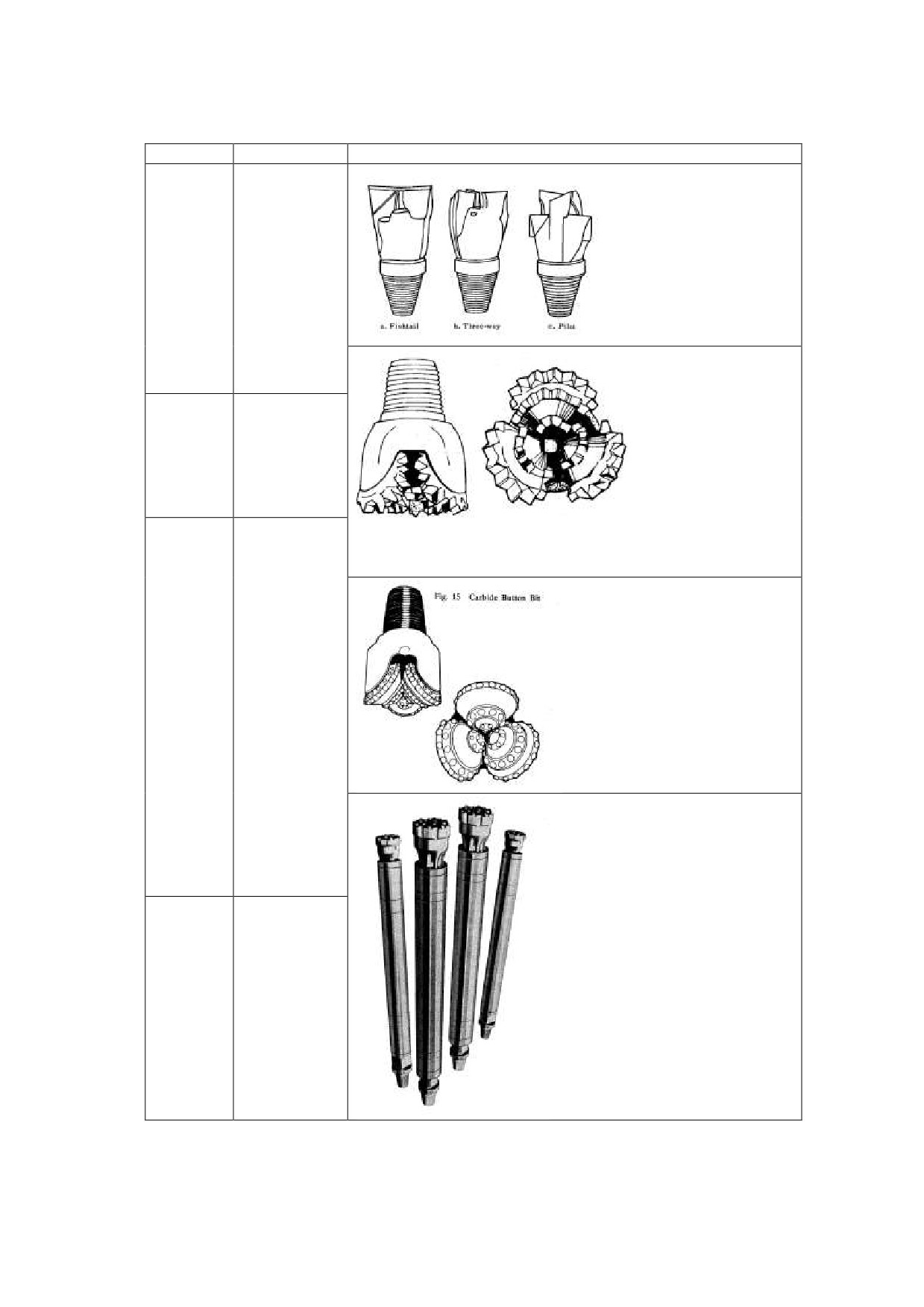
As shown in Table 4, DDCA uses the three types of rotary bit i.e. drag bit, tri-cone tooth bit and
carbide button bit. Commonly to each type of rotary bit, a bit has a pin connection of API Regular
(Reg.) standard. The Table 5 shows the connections of each size of the rotary bits.
Table 5 Connection of Rotary Bit
Bit Size
Connection
3-1/2” - 4-1/2”
2-3/8” Reg. Pin
4-3/2-4” - 5-1/8”
2-7/8” Reg. Pin
5-3/8” - 7-3/8”
3-1/2” Reg. Pn
7-7/8” - 9”
4-1/2” Reg. Pin
9-5/8” - 15”
6-5/8” Reg. Pin
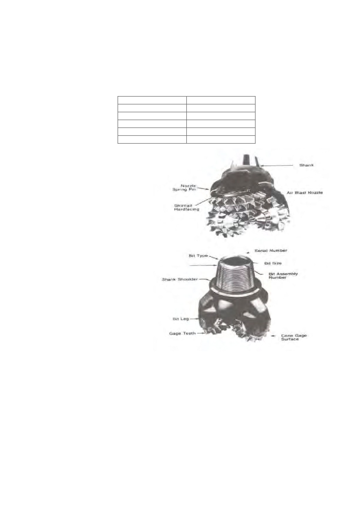
Figure 4 shows the structure of
tri-cone tooth bit.
The drillers
shall execute the following bit
control to realize the proper
drilling operation:
-
Prompt checking of wearing
and cleaning of bit after
pulling-out from the hole,
-
Checking of diameter to
prevent from the decrease of
hole diameter. In case of drag
bits, standard diameter shall be
kept by welding,
-
Record of bit operation hours
with necessary information
such as rotation speed, weight
on bit, pump pressure etc.
Source: Australian Drilling Industry Training Committee Limited
Figure 4 Structure of Tri-cone Tooth Bit
8
DDCAP Technical Manual for Drilling Works
For Technical Support Plan for the Drillers in DDCA
2.3 DTH AND DTH BIT (TA CODE 2-3)
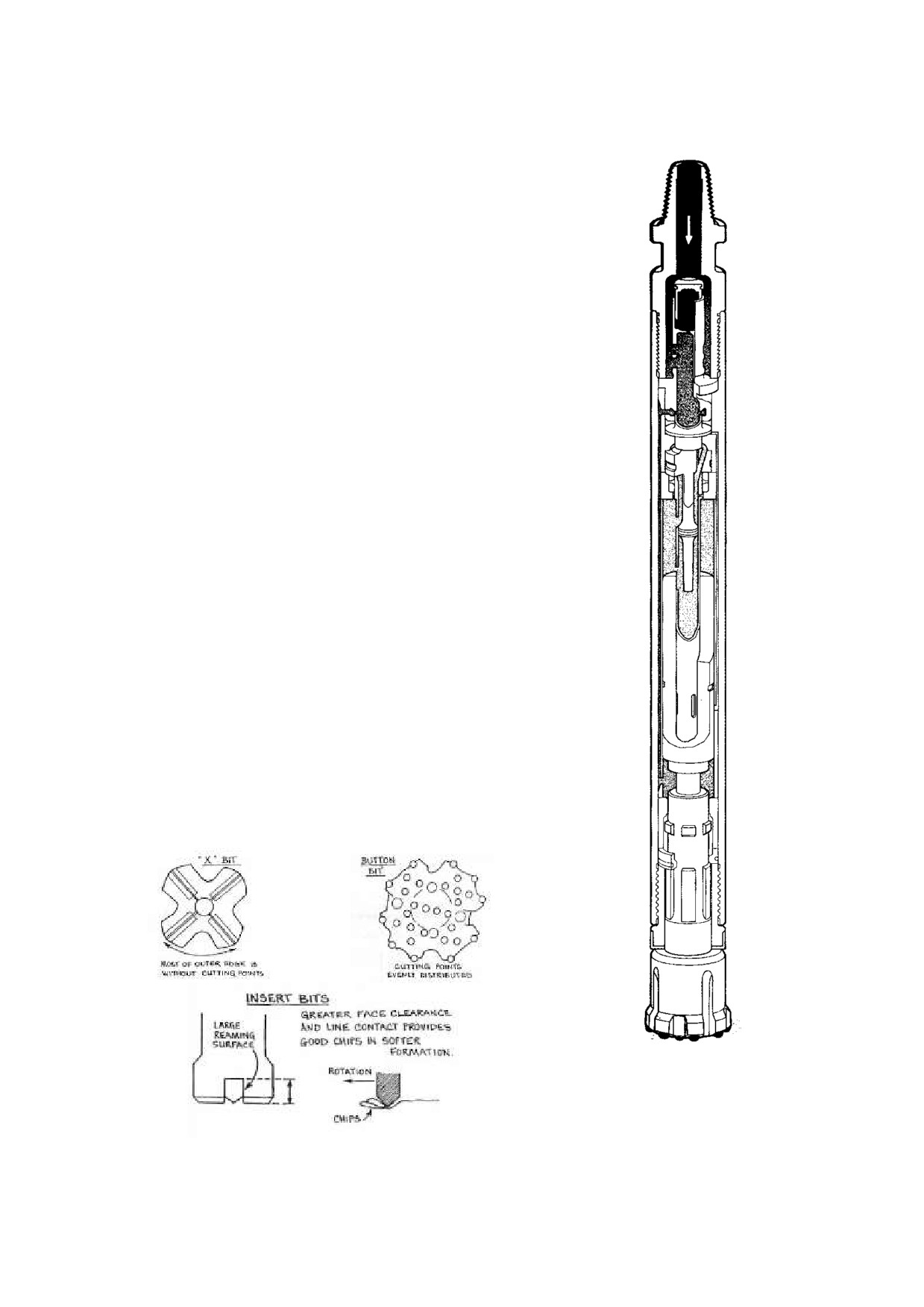
Figure 5 shows the structure of DTH. The DTH is a rotary
percussive tool which operates at the bottom of the hole being
drilled. It is attached at the end of the drill string, and
powered by compressed air flowing down the centre of the drill
string into the hammer. The air operates a piston within the
hammer which strikes the rear end of the drill bit providing a
percussive action. Porting, and in some cases valves within
the hammer cause the piston to return to the upward position
and then strike again in a continuous sequence. The hammer
and drill string is rotated by the drilling machine on the surface
which also provides necessary feed force, or, in a deep hole
feed hold back force. Air exhausted from the hammer
operation and additional air by-passed through the hammer is
then used to cool the drill bit and evacuate drill cuttings from
the hole. The DTH is very effective in drilling hard rock and
the essential difference to rotary drilling is that the percussive
rock breaking effort is being conducted on the hole bottom.
Feed forces are only required to keep to bit on the bottom of the
hole and any further effort
(feed force) will not increase
penetration but damage the hammer tool. Experienced rotary
drillers shold guard againt a natural tendency to overfeed.
Figure 6 shows the structure of DTH bits. Hammers provide
light rigs with the ability to drill hard rodk; rock that cannot be
drilled economically or quickly using any other method unless
a much heavier rig is available.
For most hammer drilling, button bits provide lower costs per
meter drilled as they give:
Faster penetration and
Longer runs between grinding.
The button bit drills more efficiently because the percussive
forces are distributed over the bottom of the hole. Chisel or
cross bits concentrate the energy at the centre of the hole.
Most of the outer edge is without effective cutting points.
Source: Atlas Copco
Figure 5 Structure of DTH
Source: Australian Drilling Industry Training Committee
Figure 6 Structure of DTH Bits
9
DDCAP Technical Manual for Drilling Works
For Technical Support Plan for the Drillers in DDCA
However, cross “X” or insert bits are more resistant to heavy gauge wear. In some formations,
insert bits drill straighter than button bits, and in softer formations which are “scooped out” rather
than shattered, insert bits can give better penetration. Button bits are available, with buttons of
varying sizes to suit different formations and to suit the energy output of the hammer. Button
patterns are varied to suit the rock and the hole size. Bits with a cutting edge at the back shoulder
are supplied to drill “backwards” when caving could be a problem.
In order to keep the good drilling progress, buttons of bit shall be kept being sharped. The drillers
are required to execute the proper bit sharpening by referring the manufacturer’s manual of DTH.
10
DDCAP Technical Manual for Drilling Works
For Technical Support Plan for the Drillers in DDCA
2.4 RIG ACCESSORY (TA CODE 2-4)
2.4.1 CONTENTS OF RIG ACCESORY
The rig accessory shall consist of drilling string elements and handling tools. They are major
tools for the drilling works to be attached to each drilling rig. Table 6 shows the contents of rig
accessories for a set of DDCA’s new rotary cum DTH drilling rig of 150 m in capacity which are
currently under procurement. Total of 6 rigs are to be procured and they are planed to be hired to
the private drilling companies. The major components of rig accessory are drill pipes, drill collars,
subs, DTHs, DTH bits, rotary bits etc. The quantities of each element in Table 6 were calculated
for the drilling of wells of 150 m in depth by using DTH drilling method and mud drilling method.
This section describes the use and the specifications of each element for the purpose of proper use
and selection by the drillers.
Table 6 Rig Accessories DDCA’s New Drilling Rig of 150 m Capacity
No.
Description
Unit
Qty
Drill pipes 41/2'' 0.D flush type with API 31 1/2''IF BOX and pin joints
1
Pcs
30
furnished with wrech squares and steel made protectors,6m long/pc
Drilling collars 5''0.D,2''IF BOX and pin joints,furnished with wretch squares
2
Pcs
3
and steel protectors,6m long/pc
3
Hoisting swivel API 1/2'' IF Pin joint
Pcs
3
4
Hoisting plug API 1/2'' IF Pin joint
Pcs
3
5
Drill pipes collar hanger
Pcs
3
6
Cross over sub API 3 1/2 IF BOX and pin
Pcs
3
DTH Hammer assembly for 6 1/4''(150mm) hole drilling API 3 1/2 Regular pin
7
Assy
3
and 8'' to 10'' hole drillling
8
DTH Hammer assembly for 12''(300mm) hole drilling API 3 1/2 Regular pin
Assy
3
9
DTH Button Bit for 12''(300mm) hole drilling
Pcs
5
Bit sub for drill pipes/collar to 6 1/4'' DTH Hammer API 3 1/2'' Regular box
10
Pcs
3
and API 3 1/2'' IF Box joint
Bit sub for drill pipes/collar to 6 1/4'' DTH Hammer API 3 1/2'' Regular box
11
Pcs
3
and API 3 1/2'' IF Box joint
12
DTH Button bit for 6 1/4''(159mm) hole drilling
Pcs
10
13
DTH Button bit for 8 1/4''(216mm) hole drilling
Pcs
10
14
DTH Button bit for 10''(254mm) hole drilling
Pcs
5
Bit grindeer for button bit and body dressing,furnished with 15 m long high
16
Pcs
1
pressure air hose
17
Tricone roller bits 6 1/2'' dia
Pcs
4
18
Tricone roller bits 8 1/2'' dia
Pcs
4
19
Tricone roller bits 10 1/2'' dia
Pcs
4
20
Tricone roller bits 12 1/2'' dia
Pcs
4
21
Roller bits 8 1/2'' dia
Pcs
4
22
Roller bits 10 1/2'' dia
Pcs
4
23
Roller bits 12 1/2'' dia
Pcs
4
24
Roller bits 14 1/2'' dia
Pcs
4
25
Drag bits three winged 8 1/2'' dia
Pcs
4
26
Drag bits three winged 10 1/2'' dia
Pcs
4
27
Drag bits three winged 12 1/2'' dia
Pcs
4
28
Drag bits three winged 16 1/2'' dia
Pcs
0
29
Roller bit 16'' dia for soft formation
Pcs
0
Stabilizer for
6 1/4'' hole body dia,1.5m long API 3 1/2 IF BOX and pin joints
30
Pcs
3
furnished with wretch squares and steel made thread protectors on both ends
Stabilizer for
8 1/2'' hole 5'' body dia,1.5m long API 3 1/2 IF BOX and pin
31
joints furnished with wretch squares and steel made thread protectors on both
Pcs
3
ends
Stabilizer for
10'' hole 5'' body dia,1.5 long API 3 1/2 IF BOX and pin joints
32
Pcs
3
furnished with wretch squares and steel made thread protectors on both ends
11
DDCAP Technical Manual for Drilling Works
For Technical Support Plan for the Drillers in DDCA
No.
Description
Unit
Qty
Stabilizer for
12'' hole 5'' body dia,1.5m long API 3 1/2 IF BOX and pin joints
33
Pcs
3
furnished with wretch squares and steel made thread protectors on both ends
2.4.2 DRILL STRING ELEMENTS
The composition of different tools and elements as rotary subs, drill rods, stabilizers, drill collars,
reamers, down the hole hammers with various bits, as well as tricone roller bit and drag bits,
starting from the pin of the rotation head and ending with the bit on the bottom of the hole, is
called “DRILL STRING”. The three major functions to be performed by the drill string
are:
a. To transmit rotation from the drill unit to the drill bit
b. To transmit feed pressure (bit weight) from the drill unit to the drill bit
c. To provide passage for air or drill fluid to the bottom of the hole to operate the down the
hole hammer, to cool the drill bit, to flush the cuttings and to lift them up to the surface.
Resulting from these three major functions, the drill string is subject to various kinds of stress such
as torsion, tension bending, buckling and compression depending upon borehole depth, hole
diameter directions etc.
Because of some fact, that almost the total length of the drill string is placed below the ground level,
that all elements of the string are connected through threads and that of the above mentioned
various kinds of stress are caused considerable wear on the whole drill string, care has to be taken
that all elements but in particular threads are in good working condition in order to avoid any
breaking in the string. Therefore it is the responsibility of the Driller in charge and of the Shift
Operators to check various elements of the drill string carefully before being lowered in the
borehole. It is once more emphasized that only equipment in proper working condition should be
used in the borehole. But also drill string handling tools as bit brakers, clamps, chain wrenches,
lifting caps, etc have to be checked before use and should also be in proper working condition.
The strongly requested checking and controls by the personnel concerned are considered as
preventive measures at the drill sites in order to avoid difficult time and money consuming
fishing work hindering drilling crews from good performance. Figure 7 shows the standard
assembly of drill string.
12
DDCAP Technical Manual for Drilling Works
For Technical Support Plan for the Drillers in DDCA
Drive shaft
The drive shaft pin of the rotation gear box is threaded with 31/2" API Reg. Pin and is the
connector from the drill unit to the drill string.
Rotary Substitutes "SUBS"
Rotary substitutes commonly known as "SUBS" are elements of the drill string and are
used where threads of one size or type must be completed together with threads of another size or
type. These subs are called "Cross Over subs". Other subs are used as wear prevention at
connection points that are frequently made up and broken out. These subs are called "Saver Subs."
Casing driver subs are to connect steel surface/conductor casing to the top drive head of
the rig. This enables the drilling by the casing or the mud/air circulation to remove the
sediment which disturbs the casing installation to the desired depth. DDCA has casing
driver subs for 65/8", 85/8", 103/4", 123/4" and14" O.D casings with API 5L line pipe thread;
the connector is 31/2 API IF Box.
Elements of the drill string which are used with our rotary rigs and which have to be coupled in
the drill string with the help of subs are as follows:
Drill Pipes and Drill Collars
Drill pipe is a type of piping used on a drilling rig. It helps with wellbore drilling, which is the
process of digging a hole in the ground in order to access a particular natural resource, such as oil
or water. The pipe pumps drilling fluid, which generates pressure to keep unwanted fluids out of
the liquid pumped, removes drill cuttings, and helps to cool and clean the drill bit. It is one of
the most significant member of the drill string. It is available in different diameters
according to requirements, as FLUSH JOINT DRILL ROD AND UPSET DRILL ROD,
(here the tool joint is larger in diameter than the pipe itself). Tool joints are threaded with
male and female threads for connecting in the drill string. The material of drill pipes is
considered of having the best physical properties and to provide a combination of hardness,
strength and ductility.
DDCA has various size of drilling pipes such as:
51/2" O.D Fitted with 31/2" API IF Box Pin
51/4" O.D fitted with 31/2" API Reg. Box Pin
41/2" O.D fitted with 31/2" API Reg. Box Pin
31/2" O.D fitted with 23/8" API IF Box Pin
31/2" O.D fitted with 27/8" API IF Box Pin.
The drillers are required to correctly grasp the specifications of drill pipes which they use,
i.e. nominal diameter, connection (API Reg. or IF), outside and inside diameters, unit
weight. Table 7 show the general capacity of API drill pipes
Table 7 Capacity of API Drill Pipe
Nominal
Threads
Unit Weight
OD (mm)
ID (mm)
Diameter
/ inch
(kg / m)
2-3/8”
60
47
4
11.0
2-7/8”
73
54.6
4
17.0
3-1/2”
88.9
70.3
4
21.0
4-1/2”
114.3
97.1
4
27.0
5-1/2”
139.7
121.4
32.7
Drill collar is heavy weight pipe which shall be connected between rotary bit and drill pipes. In
water well drilling, one to three tons of drill collars is used and the weight on bit shall be within the
total weight of drill collars. Table 8 shows the general capacity of API drill collars.
14
DDCAP Technical Manual for Drilling Works
For Technical Support Plan for the Drillers in DDCA
Table 8 Capacity of API Drill Collar
Connection
OD (inch)
ID (inch)
Unit Weight (kg/m)
NC23-31
3-1/8"
1-1/4"
NC26-35 (2-3/8 IF)
3-1/2
1-1/2"
39.7
NC31-41 (2-7/8 IF)
4-1/8"
2"
51.6
NC35-47
4-3/4"
2"
73.8
NC38-50(3-1/2 IF)
5"
2-1/4"
79.3
NC44-60
6"
2-1/4"
122.9
NC44-60
6"
2-13/16"
113.0
NC44-62
6-1/4"
2-1/4"
134.7
NC46-62(4IF)
6-1/4"
2-13/16"
124.7
NC46-65(4IF)
6-1/2"
2-1/4"
148.0
NC46-65(4IF)
6-1/2"
2-1/4"
138.1
NC46-67 (4 IF)
6-3/4"
2-13/16"
160.7
NC50-70 (4 1/2 IF)
7"
2-13/16"
174.1
NC50-70 (4 1/2 IF)
7"
2-13/16"
165.2
NC50-72 (4 1/2 IF)
7-1/4"
2-13/16"
178.6
NC56-77
7-3/4"
2-13/16"
208.3
NC 56-80
8"
2-13/16"
224.7
6-5/8REG
8-1/4"
2-13/16"
241.1
NC61-90
9"
2-13/16"
291.7
7-5/8R E G
9-1/2"
3"
322.9
NC70-97
9-3/4"
3"
342.3
NC70-100
10"
3"
361.6
NC77-110
11"
3"
445.0
Stabilizer or/and Reamer
There are a number of stabilizers and reamers manufactured of different type and use in drilling
boreholes. There is the rubber stabilizer used almost only in deep oil well or water well drilling.
More common is the welded blade type stabilizer or reamer in shallow water well drilling. It is
especially effective in soft formation where "balling up" of mud and cuttings on the drill string may
be a problem. These stabilizers are generally used for the following purpose:
To avoid crocked hole drilling
To center the part of the drill string under weight (mostly drill collars) and to make the drill
string more stiff although using more weight.
To prevent the bit from wandering.
But there are also special reamers or hole openers known, placed immediately above the bit in
order to stabilize the bit but also to enlarge the borehole immediately after the pilot bit. (e.g.
Carbide Insert Blade Bit Assy.). DDCA has some kinds of stabilizer sucy as 65/8" O.D fitted
with 41/2" API Reg. Box Pin.
Down the Hole Hammer (DTH), Bits, Drag Bits, Roller Bits
These tools as members of the drill string are doing the actual drilling work on the lower end of the
drill string on the bottom of the borehole. These tools are designed and manufactured in a wide
variety in order to meet the demand originating from the property of the underground to be
penetrated.
DTH
In order to overcome these problems which may result from lack of experience or proper
knowledge of the matter by the rig operators in addition to the above given hints each driller shall
refer to the operation and maintenance manual of the manufacturer of DTH. One copy will have
to be with a driller incharge for the purpose of training his crew and the other copy always to be
available at the drill site for the shift operators disposal in order to have information required when
on duty. The operation and Maintenance Manual shall contain all necessary general information
on:
Preparation for Drilling
15

DDCAP Technical Manual for Drilling Works
For Technical Support Plan for the Drillers in DDCA
Drilling Operation
Maintenance(sharpening bit) which have to be studied and followed thoroughly by the rig
operators and considered as a working guide in order to improve performance of this very
expensive equipment. Emphasis has especially to be put on the “CAUTIONS” mentioned in
the Operation and Maintenance Manual indicating the most decisive actions for proper
operation service and maintenance of the equipment.
In addition to the instructions and guidelines given above general cleanliness at the site
proper handling of drill string as well as use of proper drill oil has to be put on the
“CAUTIONS” mentioned in the Operation and Maintenance Manual indicating the most
decisive actions for proper operation service and maintenance of the equipment.
In addition to the instructions and guideline given above general cleanliness at the site proper
handling of drill string as well as use of proper drill oil has to be maintained. Proper drill
sting handling tools have to be used in order to avoid damages of Megadrills and Megabits
and to avoid general failure. Consultation of Senior Inspector Drilling or Drilling
Superintendent should get more common in future in case of problems with equipment or
low penetration rate in order to seek advices for improving performance of tools.
DDCA has DTH such asMission Mega and Hammer drills as follows:
Model A 53-15
fitted with 31/2" API Reg. Box
Model A 63-15
fitted with 41/2" API Reg. Pin
Model A 100-10 fitted with 65/8" API Reg. Pin
Model A 51-20
fitted with 31/2" API Reg. Box
Model A 43-15
fitted with 25/8" API Reg. Box
Drag Bits, Tri-cone Bits and Tri-cone Roller Bits
These three types of rotary bits are major types for DDCA’s drilling works. Please refer to section
2-1 and 2-2 of this manual for the further explanation.
2.4.3 IDENTIFICATION OF SIZE AND TYPE OF THREADS
Operational trouble may sometimes be caused by not having the right tool-at the right place at the
right time. But the Driller incharge as well as the stores staff must be able to identify threads of
drill rods, bits, stabilizers and other tools of the drill string as well as threads of subs which are
required to assemble the drill string. Identification of threads manufactured according to
API-Standard is possible by measuring the PIN BASE DIAMETER and COUNTER BORE
DIAMETER at box mouth as well as by determination of threads per inch. Table 9 shows an
identification chart and instructions giving how to identify properly threads and how to determine
on the subs required at drill sites for the drilling operation.
Table 9 Identification of API Threads
Thread Type
Thread per inch
Thread Angle
Pin diameter at base
Box diameter at counterbore
REG
5
60°
66.68
68.26
2-3/8
FH
-
-
-
-
IF
4
60°
73.05
74.61
REG
5
60°
76.20
77.79
2-7/8
FH
-
-
-
-
IF
4
60°
86.13
87.71
REG
5
60°
88.90
90.49
3-1/2
FH
5
60°
101.45
102.79
IF
4
60°
102.01
103.58
REG
5
60°
117.48
119.06
4-1/2
FH
5
60°
121.72
123.83
IF
4
60°
133.35
134.94
6-5/8
REG
4
60°
152.20
153.99
16

DDCAP Technical Manual for Drilling Works
For Technical Support Plan for the Drillers in DDCA
2.5 CASING TOOLS (TA CODE 2-5)
2.5.1 SIZE AND TYPE OF STEEL CASING PIPE
(1) Steel Casing Pipes
The steel casing pipes are used as the surface casing and/or the conductor casing. DDCA has
various types and standards of steel casing pipes. Normally, casing pipes are used as temporary
casings. Therefore they are pulled out from the borehole after the completion. In this reason
casing pipes are with threaded flush for the easiness of the handling. Stadards of API 5L-B, JIS
STPG Sch-40, JIS SGP, DIN Medium are popularly used for the steel casing. Their sizes are shown
in Table 10, Table 11, Table 12 and Table 13.
Table 10 Size of API 5L-B Steel Pipes
ND
ND
Thickness
Unit Weight
OD(mm)
ID(mm)
(mm)
(inch)
(mm)
(kg/m)
3-1/2"
88.9
80.9
4
8.37
3-1/2"
88.9
79.3
4.8
9.95
3-1/2"
88.9
77.9
5.5
11.31
4-1/2"
114.3
104.7
4.8
12.96
4-1/2"
114.3
103.9
5.2
13.99
4-1/2"
114.3
103.1
5.6
15.01
4-1/2"
114.3
102.3
6
16.02
6-5/8"
168.3
158.7
4.8
19.35
6-5/8"
168.3
157.1
5.6
22.47
6-5/8"
168.3
154.1
7.1
28.22
6-5/8"
168.3
152.5
7.9
31.25
8-5/8"
219.1
207.9
5.6
29.48
8-5/8"
219.1
206.3
6.4
33.57
8-5/8"
219.1
205.1
7
36.61
8-5/8"
219.1
203.3
7.9
41.14
8-5/8"
219.1
202.7
8.2
42.65
8-5/8"
219.1
201.7
8.7
45.14
8-5/8"
219.1
200.1
9.5
49.1
10-3/4"
273
260.2
6.4
42.09
10-3/4"
273
258.8
7.1
46.57
10-3/4"
273
257.4
7.8
51.03
10-3/4"
273
255.6
8.7
56.72
10-3/4"
273
254.4
9.3
60.5
12-3/4"
323.8
311
6.4
50.11
12-3/4"
323.8
309.6
7.1
55.47
12-3/4"
323.8
308
7.9
61.56
12-3/4"
323.8
307
8.4
65.35
12-3/4"
323.8
306.4
8.7
67.62
12-3/4"
323.8
304.8
9.5
73.65
12-3/4"
323.8
303.2
10.3
79.65
14"
355.6
342.8
6.4
55.11
14"
355.6
341.4
7.1
61.2
14"
355.6
339.8
7.9
67.74
14"
355.6
338.2
8.7
74.42
14"
355.6
336.6
9.5
81.08
14"
355.6
335
10.3
87.71
16"
406
393.2
6.4
63.13
16"
406
391.8
7.1
69.91
16"
406
390.2
7.9
77.63
16"
406
388.6
8.7
85.32
16"
406
387
9.5
92.98
18"
457
442.8
7.1
78.77
18"
457
441.2
7.9
87.49
18"
457
439.6
8.7
96.18
17

DDCAP Technical Manual for Drilling Works
For Technical Support Plan for the Drillers in DDCA
ND
ND
Thickness
Unit Weight
OD(mm)
ID(mm)
(mm)
(inch)
(mm)
(kg/m)
18"
457
438
9.5
104.84
18"
457
436.4
10.3
113.46
Table 11 Size of JIS STPG Sch-40 Steel Pipes
ND
ND
Thickness
Unit Weight
OD(mm)
ID(mm)
(mm)
(inch)
(mm)
(kg/m)
80
3
89.1
78.1
5.5
11.3
90
3-1/2
101.6
90.2
5.7
13.5
100
4
114.3
102.3
6
16
125
5
139.8
126.6
6.6
21.7
150
6
165.2
151
7.1
27.7
200
8
216.3
199.9
8.2
42.1
250
10
267.4
248.8
9.3
59.2
300
12
318.5
297.9
10.3
78.3
350
14
355.6
333.4
11.1
94.3
400
16
406.4
381
12.7
123
450
18
457.2
428.6
14.3
156
Table 12 Size of JIS SGP Steel Pipes
ND
ND
Thickness
Unit Weight
OD(mm)
ID(mm)
(mm)
(inch)
(mm)
(kg/m)
80
3
89.1
80.7
4.2
8.794
90
3-1/2
101.6
93.2
4.2
10.089
100
4
114.3
105.3
4.5
12.186
125
5
139.8
130.8
4.5
15.015
150
6
165.2
155.2
5
19.754
175
7
190.7
180.1
5.3
24.2
200
8
216.3
204.7
5.8
30.1
225
9
241.8
229.4
6.2
36
250
10
267.4
254.2
6.6
42.4
300
12
318.5
304.7
6.9
53
350
14
355.6
339.8
7.9
67.7
400
16
406.4
390.6
7.9
77.6
450
18
457.2
441.4
7.9
87.5
Table 13 Size of BS Heavy Steel Pipes
ND
ND
Thickness
Unit Weight
OD(mm)
ID(mm)
(mm)
(inch)
(mm)
(kg/m)
80
3"
88.75
79.05
4.85
10.0
100
4"
114.05
103.25
5.4
14.4
125
5"
139.65
128.85
5.4
17.8
150
6"
165.2
154.4
5.4
21.1
Figure 8 shows the specifications chart giving indication on what tools and casings have to be used
at drill sites in order to complete boreholes of the required final diameters as requested by the
hydrogeologist. It will help the driller in charge to check at he site whether he has got the proper
tools or to enable him to arrange for the required tools and casings respectively. It should be
considered as general guideline when this type of casings is used for water well drilling.
Each of the columns is giving particulars on casings, couplings, drill bit as well as clearance in
annular spaces required to allow the drill bit to pass, to allow proper running of casing and to insert
gravel pack envelope around screens.
In column 2, 3, 4 and 7 are particulars of casings as O.D. Wall thickness and O.D of couplings
listed. Column 5 is indicating the max. Diameter of drill bit which may be run in the casings with a
clearance as shown in column 6. This clearance is a result from J.D casing column 4 and bit size
column 5. It is important for the Drillers incharge and the Shift Operator to know as what is the bit
clearance in order to avoid jamming of the drill string in the casings. In column 7 it is the O.D. of
18
DDCAP Technical Manual for Drilling Works
For Technical Support Plan for the Drillers in DDCA
the casing coupling listed important for th be determination of the bit size required to run casings
without problems. Now in columns 8 and 9 the required bit sizes are listed depending from the O.D
of casings columns 2 and the O.D. of couplings column 9 in order to have the required clearance
for running casings and inserting gravel pack.
The annular space listed in column 10 is the minimum clearance required which will enable the
Driller incharge or Shift Operator to run casings without trouble provided he has not drilled a
crooked borehole and the borehole has got throughout the same required diameter.
The annular space listed in column II between casing O.D. and borehole wall refers to artificially
gravel packed boreholes drilled in unconsolidated soft soil formation where an effective gravel
envelop around the screens is required in order to get sand free water out. As already mentioned
above this chart is only giving general indication while in some instances special arrangements or
combinations of bit size and casing diameter may be necessary. But even in this respect the listed
diameter of casings and drill bits may help to find the correct decision.
19
DDCAP Technical Manual for Drilling Works
For Technical Support Plan for the Drillers in DDCA
(2) PVC Casing and Screen Pipes
Most of the case in Tanzania, PVC pipes are used as the production casing and screen pipes.
DDCA mainly use the product of the PVC manufacturer, PLASCO, of which the sizes are shown in
Table 14. The products with the remarks of 4”, 5”, 6”, 8” and 10” casing are the standard casing
types.
5” casings are standard type for handpump wells and 6” casings are for wells for piped
water supply schemes, respectively.
Table 14 Size of uPVC Pipes
Unit
Thickness
Description
OD (mm)
ID
Weight
Remarks
(mm)
(kg/m)
FLUSH FITTING DIN4925 CASE
113
99
7
3.9
FLUSH FITTING DIN4925 CASE
125
110
7.5
4.3
4" Casing
FLUSH FITTING DIN4925 CASE
140
124
8
5.2
5" Casing
FLUSH FITTING DIN4925 CASE
165
146
9.5
7.3
FLUSH FITTING PLASCO CASE
165
150
7.5
5.9
6" Casing
FLUSH FITTING DIN4925 CASE
200
177
11.5
10.8
FLUSH FITTING PLASCO CASE
200
182
9
8.6
FLUSH FITTING DIN4925 CASE
225
199
13
13.7
FLUSH FITTING PLASCO CASE
225
205
10
10.7
8" Casing
FLUSH FITTING PLASCO CASE
250
225
12.5
15
FLUSH FITTING DIN4925 CASE
280
248
16
21.3
FLUSH FITTING PLASCO CASE
280
255
12.5
16.9
10" Casing
FLUSH FITTING PLASCO CASE
315
285.4
14.8
22.4
Source: Catalog of PLASCO
2.5.2 CASING HANDLING TOOLS
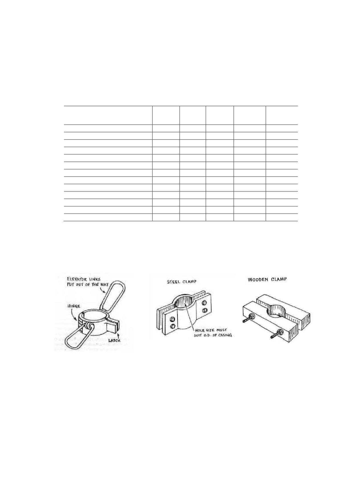
Steel or wooden clampes, or casing elevators (See Figure 9) are usually used to install and/or pull
out the casing string. In addition, wire slings and shackles shall be prepared on site according to
the total weight of the casing string.
Figure 9 Casing Lifting Tools
21
DDCAP Technical Manual for Drilling Works
For Technical Support Plan for the Drillers in DDCA
2.6 DRILLING EQUIPMENT (TA CODE 2-6)
This section describes the major equipment for drilling works by rotary cum DTH drilling. It
consists of drilling rig, mud pump, air-compressor, cargo truck and water tank truck. DDCA is
currently procuring new drilling equipment including two drilling rigs of 300 m depth, six drilling
rigs of 150 m depth and supporting equipment and trucks.
Drillers are required to evaluate the capacity of each equipment whether or not capable to drill a
borehole of various depth, diameter and drilling method. The representative capacity of each
equipment is described below.
2.6.1 SPECIFICATION OF DRILLING RIG
Figure
10 shows the structure of
standard truck-mounted drilling rig.
Besides rig plan, generally either a
mud pump or an air-compressor is
equipped on the truck.
The representative capacity of a
drilling rig is lifting capacity
(ton).
This capacity expresses the maximum
length of drill string which can be
hold and lifted up by the drilling rig.
It is directly related to the maximum
drilling depth.
If the drilling is to be executed by
DTH down to 200 m with 4-1/2” drill
pipes without drill collar, total weight
of the drill string is:
97 kg /m x 200 m = 10 tons
With consideration of stucking of
drill string,
10 to 15 % of surplus
shall be considered as a safety factor.
10
% of safety factor is taken,
necessary lifting capacity comes to b
11 tons.
Source: National Waterwell & Drilling Association of Australia
Prior to the selection and preparation
Figure 10 Structure of Truck-mounted Drilling Rig
of the drilling equipment, drillers shall
determine the necessary drilling tools
such as drilling pipes, drill collars, bits, DTH etc. T
total weight of the drill string is calculated and shall
evaluated whether or not within the capacity of t
drilling rig.
2.6.2 CAPACITY OF MUD PUMP
Most of DDCA’s truck-mounted rigs are equipped wi
duplex mud pump, as shown in Figure
11.
T
representative capacities of mud pump are the dischar
rate and the pressure.
Discharge Rate
Necessary discharge rate shall be calculated from t
necessary annular velocity between drill pipe and ho
diameter. In general, at least 10 m/min of annular
Figure 11 Structure of Mud Pump
22
DDCAP Technical Manual for Drilling Works
For Technical Support Plan for the Drillers in DDCA
velocity is necessary for the proper removal of drilled cuttings.
In case of drilling by 8” bit and 4-1/2” drill pipe:
Necessary Disharge Rate (L/min)
= Annular Volume 22 L/m x Annular Velocity 10 m/min =220 L/min
In case of drilling by 12” bit and 4-1/2” drill pipe:
Necessary Disharge Rate (L/min)
= Annular Volume 63 L/m x Annular Velocity 10 m/min =630 L/min
Therefore, approximately 600 L/min is necessary if 12” bit drilling is used.
Pressure
Each pump has its maximum pressure according
to the discharge rate. The maximum pressure
of mud pump equipped on the DDCA’s new
drilling rig of 150 m depth is 25 bar for 600
L/min of discharge rate. Figure 12 shows an
example of separated type duplex mud pump
made by TONE and its specifications are shown
in Table 15. Discharge rate of a duplex pump
is decided by piston
(liner) diameter, stroke
length and stroke speed
(See Figure
13).
Drillers shall liner and piston of suitable
diameter for the drilling diameter and depth.
Figure 12 Duplex Mud Pump NP-700
(TONE)
Source: Australian Drilling Industry Training Cmmittee
Figure 13 Internal Structure of Mud Pump
23
DDCAP Technical Manual for Drilling Works
For Technical Support Plan for the Drillers in DDCA
Table 15 Specifications of NP-700 Mud Pump
140
127
114
102
89
Cylinder Dia. (mm)
(5-1/2")
(5”)
(4-1/2")
(4”)
(3 一 1/2")
Discharge Rate (L/min)
615
505
405
315
235
Max. Pressure (bar)
22
27
34
43
58
Stroke r.p.m
80
80
80
80
80
Drive Shart r.p.m
395
395
395
395
395
Stroke Length (mm)
130
Valve Type
Ball or Conical
Suction Hose Dia. (mm)
100 or 75
Delivery Hose Dia. (mm)
65 or 50
Power (kw)
30-4P
Total Weight (kg)
1600
Dimension (mm)
3,040 (L) x 830 (W) x 1,575 (H)
Discharge pressure is mainly caused by the friction loss of the inside of drill pipes. Therefore, the
discharge pressure is effected by the discharge rate and inside diameter and length of drill pipes as
the following:
Disharge pressure increases, if the discharge rate is increases,
Disharge pressure increases, if the pipe inside diameter becomes smaller,
Discharge pressure increases proportionally to the length of the pipe for the constant
discharge rate and pipe inside diameter.
Standard type of mud pump has the capacity of 600 L/min and 25 bar. They are sufficient for the
drilling of medium scale borehole down to 150 m with 8” to 12”. However, for large bore and/or
deep borehole drilling more than 150 m, discharge rate not less than 1,000 L/min will be necessary.
In this case, large pressure will occur if the small diameter drill pipes such as 3-1/2” are used.
Drillers are required to always check the relationship
between pipe size, depth, discharge rate and pressure to
utilize such information for the proper selection of drill
pipes and rig capacities.
2.6.3 CAPACITY OF AIR COMPRESSOR
Air-compressors for DTH drilling are of type of either
reciprocating or rotary screw.
Nowadays, rotary
screw type air-compressors are mainly used.
Representative capacities of the air-compressor are
air delivery and maximum pressure. DDCA’s new
Figure 14 Rotary Screw Air-Compressor
compressor for the drilling down to 150 m has the
PDSJ750S (21 m3/h, 21 bar)
capacities of 18.4 m3/min (650 CFM) and 17 bar
(246 psi). Figure 14 show another type of PDSJ750
air-compressor, of which air delivery is 21 m3/min
and the maximum pressure is 21 bar.
Air delivery shall be determined from the necessary
annular velocity for the proper removal of cuttings.
The optimum annular velocity is thought to be 1,220
m/min. The maximum pressure shall be not less
than the hydro static pressure of water in borehole.
If the borehole depth is 150 m, the compressor of not
less than
15 bar is preferable to be selected.
However, if the water level is deep, hydro static
Source: National Waterwell & Drilling Association of Australia
pressure becomes lower. The pressure to drive
Figure 15 Change of Drilling Speed by
Operating Pressure of DTH
24
DDCAP Technical Manual for Drilling Works
For Technical Support Plan for the Drillers in DDCA
the DTH shall be considered as well. More pressure will give the better progress of the drilling.
Figure 15 shows typical performance improvement on a hammer’s speed in hard granite at varying
air pressures. Performance varies with different makes of DTH but as an example a particular
hammer provided with 7 bar air pressure will deliver 15 blows per second of the piston striking the
bit and with 14 bar air pressure will deliver 23 blows per second. In this instance where the piston
weighs 5 kg and has a stroke of 50 cm before striking the bit, some idea of the power of a DTH can
be appreciated.
2.6.4 CAPACITY OF WATER TANK TRUCK
In general, capacity of tank of water tank truck for water well drilling is
5,000 to 6,000 L.
Necessary water volume for the drilling work is though to be three times of bore volume.
The
estimation examples are shown below:
8” x 150 m
Unit bore volme: 8 x 4 = 32 L/m
Total bore volume: 32 L/m x 100 = 3,200 L
Total necessary water: 3,200 L x 3 = 9,600 L
(2 times of transportation)
12” x 150 m
Unit bore volme: 12 x 6 = 72 L/m
Total bore volume: 72 L/m x 100 = 7,200 L
Total necessary water: 7,200 L x 3 = 21,600 L
(4 to 5 times of transportation)
2.6.5 CAPACITY OF CARGO TRUCK
The representative capacities of cargo
truck are gross vehicle weight and
payload. The payload is the maximum
load acceptable to the truk. The gross
vehicle weight is the total of truck
weight and the payload. DDCA’s new
cargo truck has a capacity of 10 tons of
payload
(See Figure
16).
This can
load approximately 370 m of 4-1/2” drill
pipe (unit weight 27 kg/m).
Figure 16 DDCA’s New Cargo Truck
25
DDCAP Technical Manual for Drilling Works
For Technical Support Plan for the Drillers in DDCA
2.7 DRILLING CALCULATION (TA CODE 2-7)
2.7.1 UNIT CONVERSION
During the drilling works, drillers are required to observe and calculate the various values from
materials and equipment actions such as weight, pressure, discharge rate etc. These values are
expressed in different unit system such as metric, imperial etc. Therefore, drillers shall acquire
the knowledge of the conversion between different unit systems. This section describes the major
units to be used for the drilling works and gives the reference for the unit conversion. Examples of
unit conversion using conversion tables are given below:
Length
100
inch
=
2.54
mm
100
mm
=
3.937
inch
10
ft
=
3.048
m
50
m
=
164.05
ft
Discharge
1000
gal/hr
=
3.785
m3/hr
1
m3/hr
=
264.2
gal/hr
1
m3/day
=
0.04167
m3/hr
25
m3/hr
=
600
m3/day
200
l/min
=
12
m3/hr
48
m3/hr
=
800
l/min
100
m3/hr
=
27.78
l/s
100
l/s
=
360
m3/hr
Pressure
1,000
Kgf/cm2
=
98.1
MPa
5
MPa
=
51
Kgf/cm2
Conversion Table
Length
m
ft
in
m
1
3.281
39.37
ft
0.3048
1
12
in
0.0254
0.0833
1
Volume
m3
gal
m3
1
264.17
gal
0.003785
1
Pressure
kN/m2
kgf/cm2
bar
lbf/in2(psi)
(kPa)
kgf/cm2
1
0.981
98.1
14.223
bar
1.02
1
100
14.504
kN/m2
0.0102
0.0098
1
0.145
(kPa)
lbf/in2(psi)
0.0703
0.0689
6.89
1
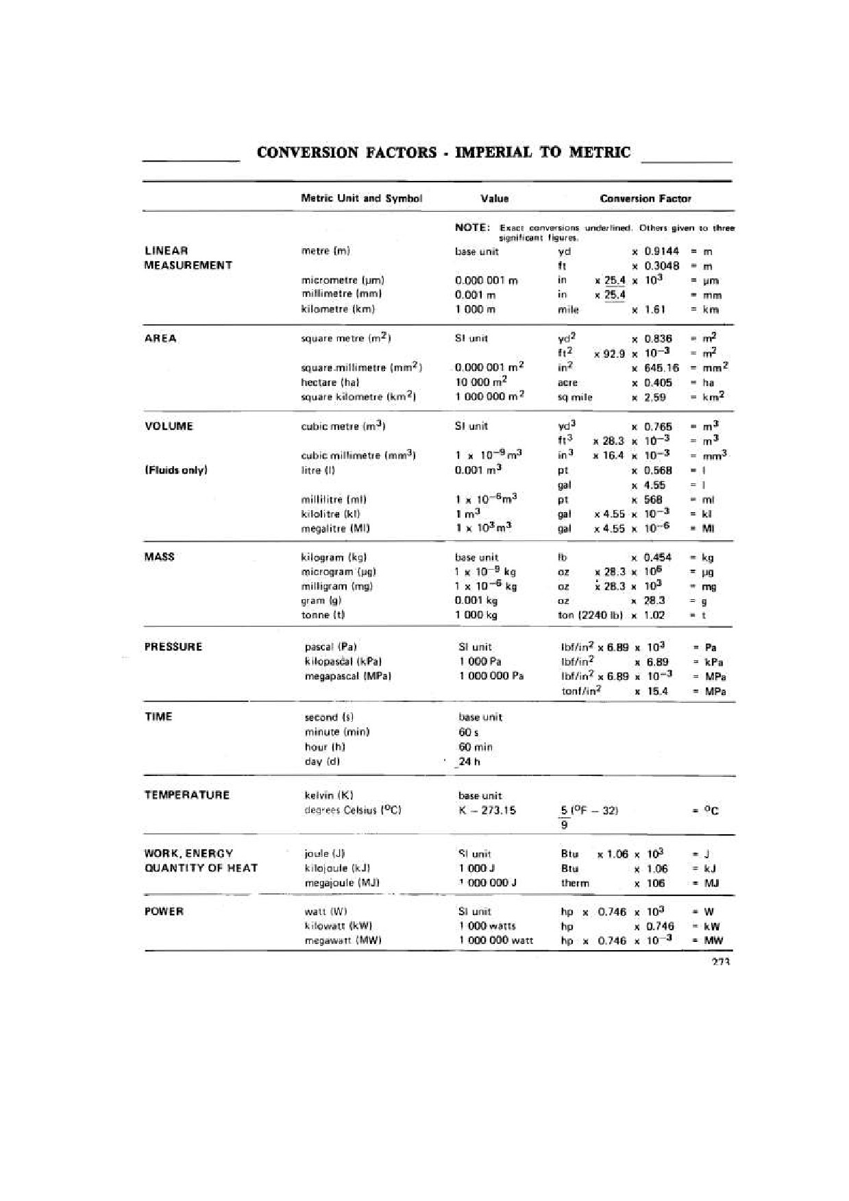
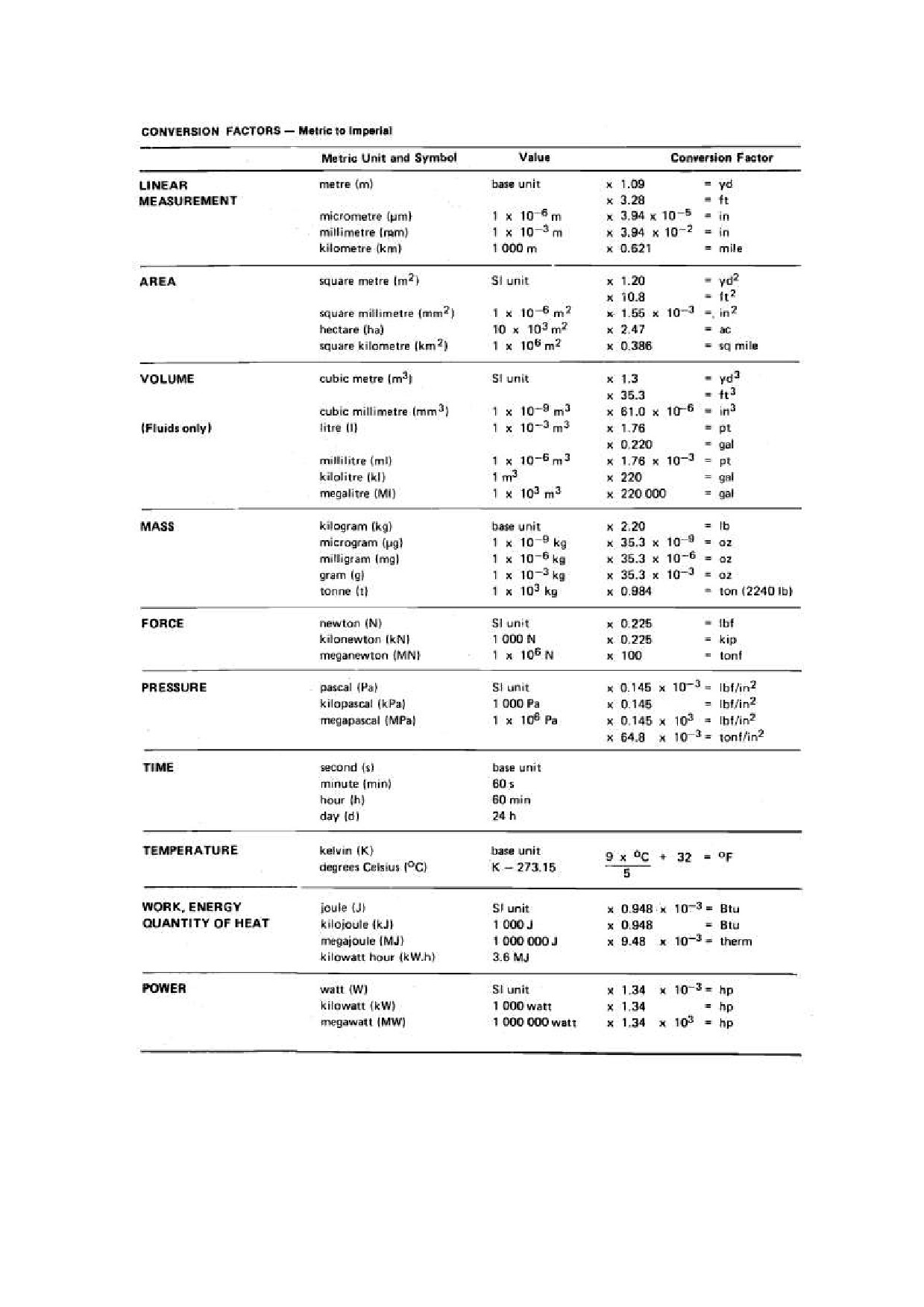
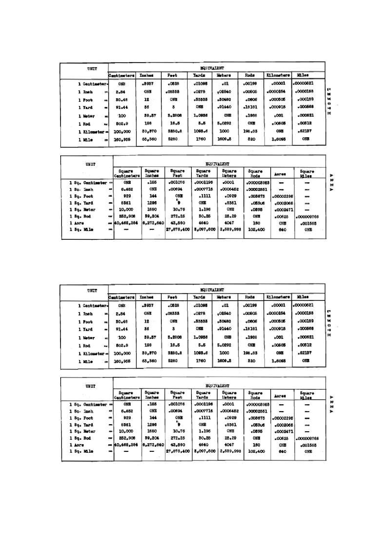
In the following pages, useful conversion factors and conversion tables are provided.
26
DDCAP Technical Manual for Drilling Works
For Technical Support Plan for the Drillers in DDCA
Table 16 Conversion Factors - Imperial to Metric
Source: National Waterwell & Drilling Association of Australia
27
DDCAP Technical Manual for Drilling Works
For Technical Support Plan for the Drillers in DDCA
Source: National Waterwell & Drilling Association of Australia
28
DDCAP Technical Manual for Drilling Works
For Technical Support Plan for the Drillers in DDCA
Table 17 Conversion Tables - Length and Area
Source: National Waterwell & Drilling Association of Australia
Table 18 Conversion Tables - Velocity and Flow
Source: National Waterwell & Drilling Association of Australia
29
DDCAP Technical Manual for Drilling Works
For Technical Support Plan for the Drillers in DDCA
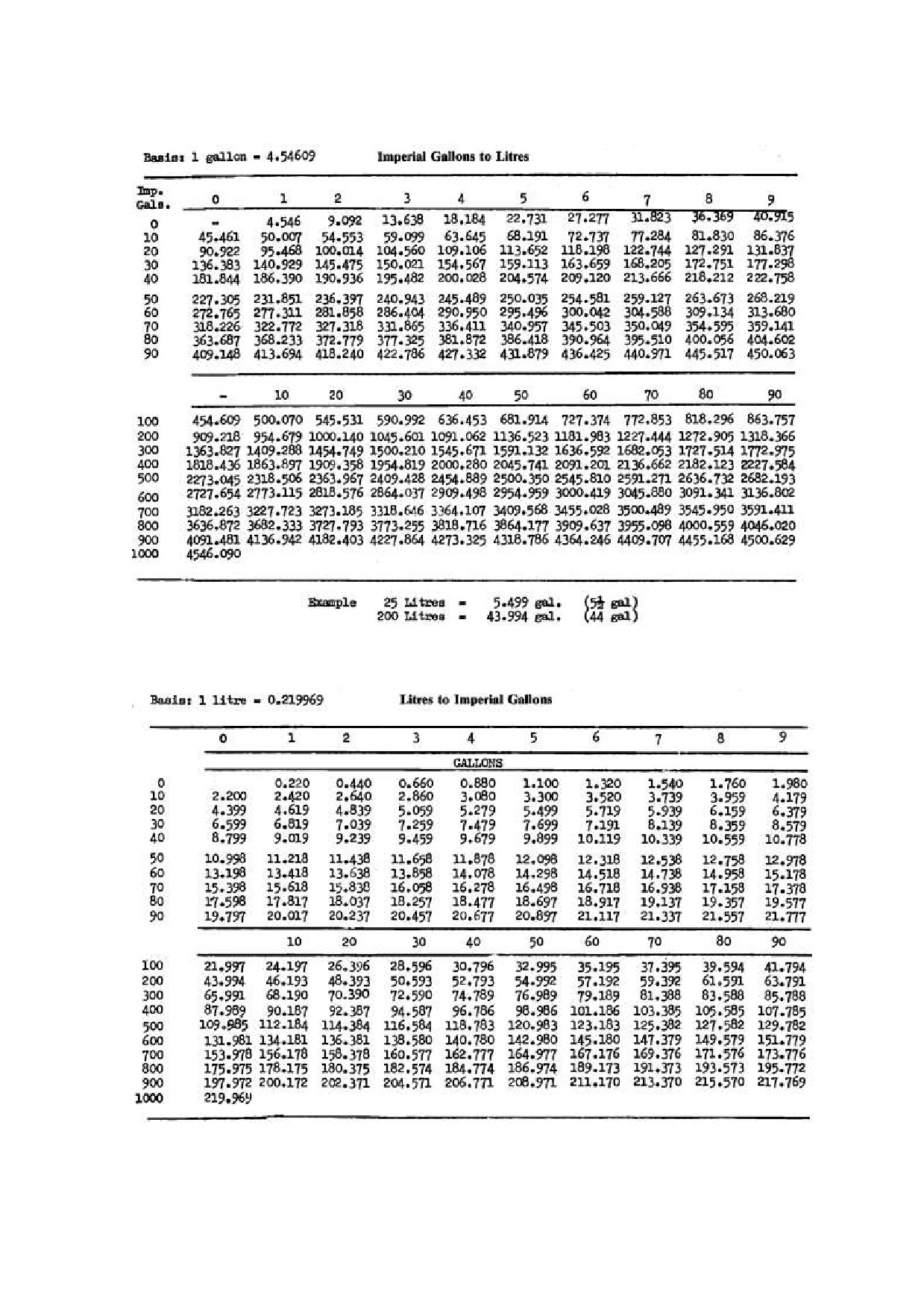
Table 19 Conversion Tables - Imperial Gallons to Litres
Source: National Waterwell & Drilling Association of Australia
Table 20 Conversion Tables - Litres to Imperial Gallons
Source: National Waterwell & Drilling Association of Australia
30
DDCAP Technical Manual for Drilling Works
For Technical Support Plan for the Drillers in DDCA
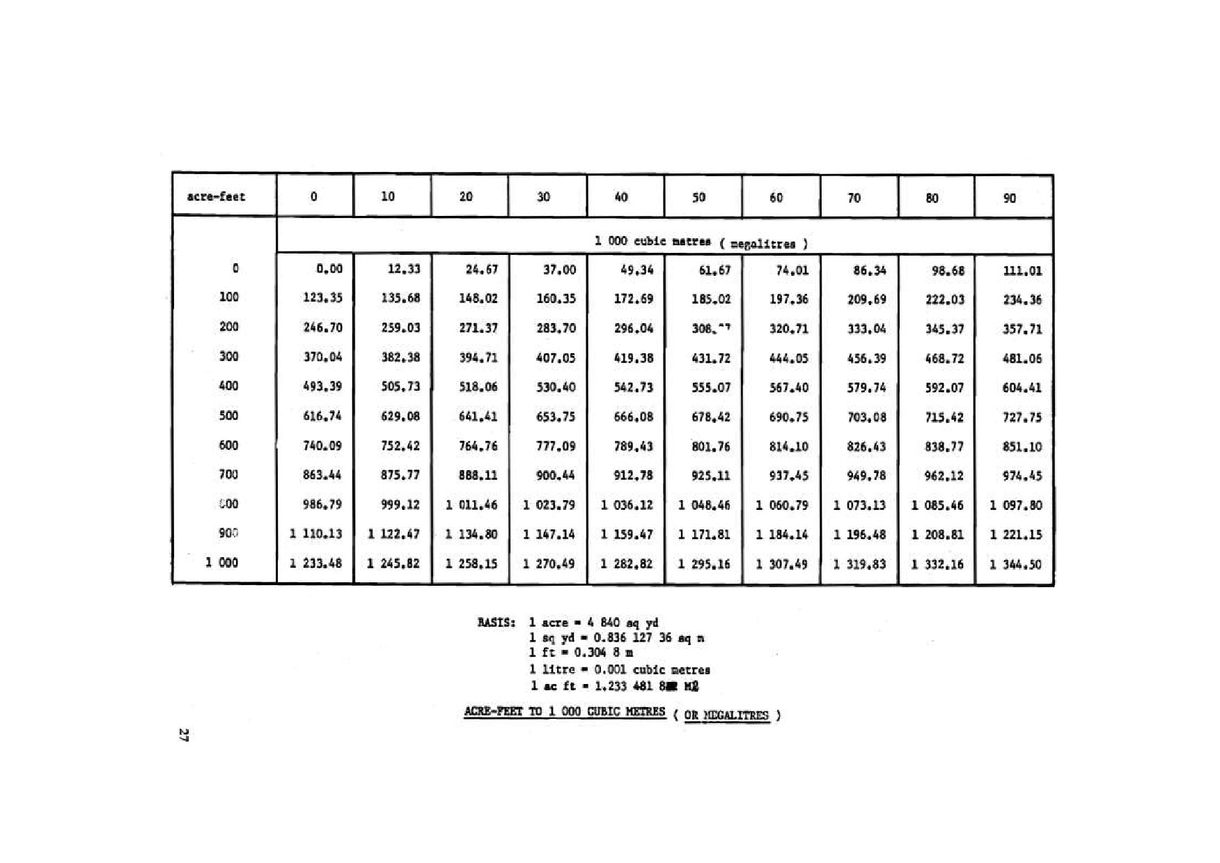
Table 21 Conversion Tables - Acre-Feet to 1,000 Cubit Meters
Source: National Waterwell & Drilling Association of Australia
31
DDCAP Technical Manual for Drilling Works
For Technical Support Plan for the Drillers in DDCA
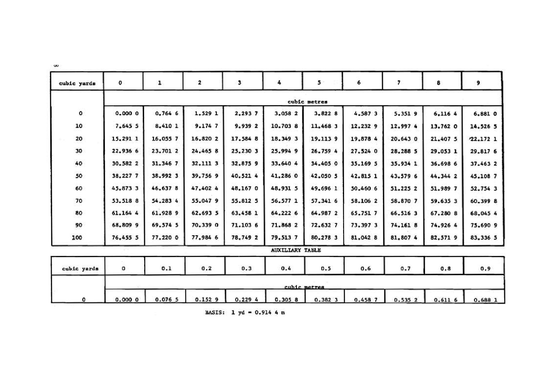
Table 22 Conversion Tables - Cubic Yards to Cubic Meters
Source: National Waterwell & Drilling Association of Australia
32
DDCAP Technical Manual for Drilling Works
For Technical Support Plan for the Drillers in DDCA
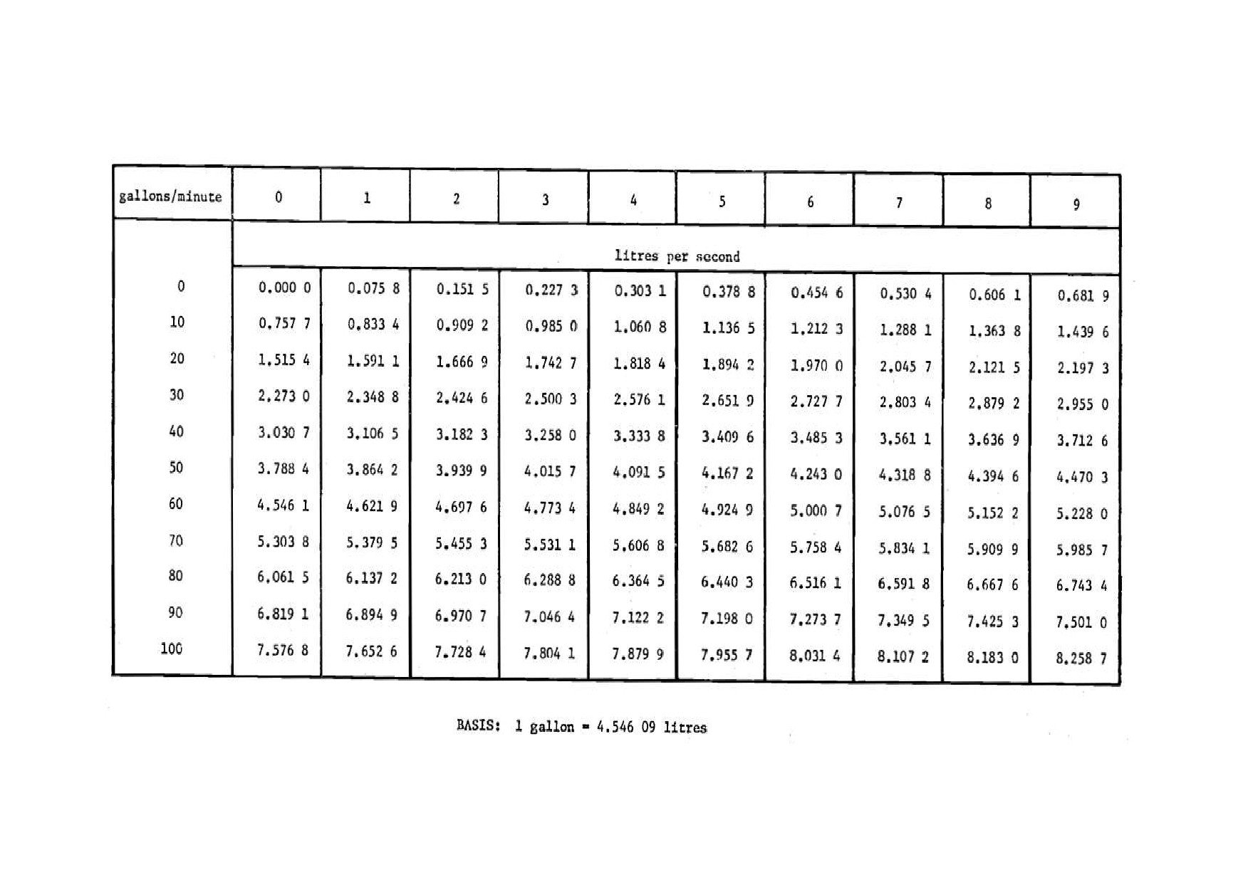
Table 23 Conversion Tables - Imperial Gallons Per Minute to Litres Per Second
Source: National Waterwell & Drilling Association of Australia
33
DDCAP Technical Manual for Drilling Works
For Technical Support Plan for the Drillers in DDCA
Table 24 Conversion Tables - Pounds Per Square Inch to Kilo Pascals
Source: National Waterwell & Drilling Association of Australia
34
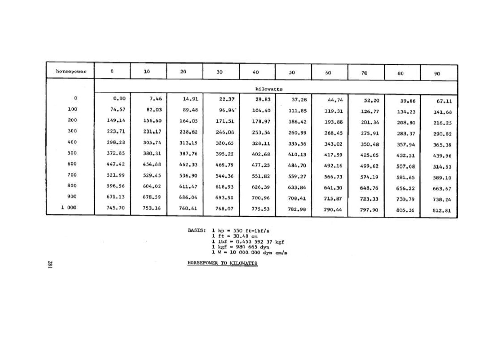
DDCAP Technical Manual for Drilling Works
For Technical Support Plan for the Drillers in DDCA
Table 25 Conversion Tables - Horsepower to Kilowatts
Source: National Waterwell & Drilling Association of Australia
35
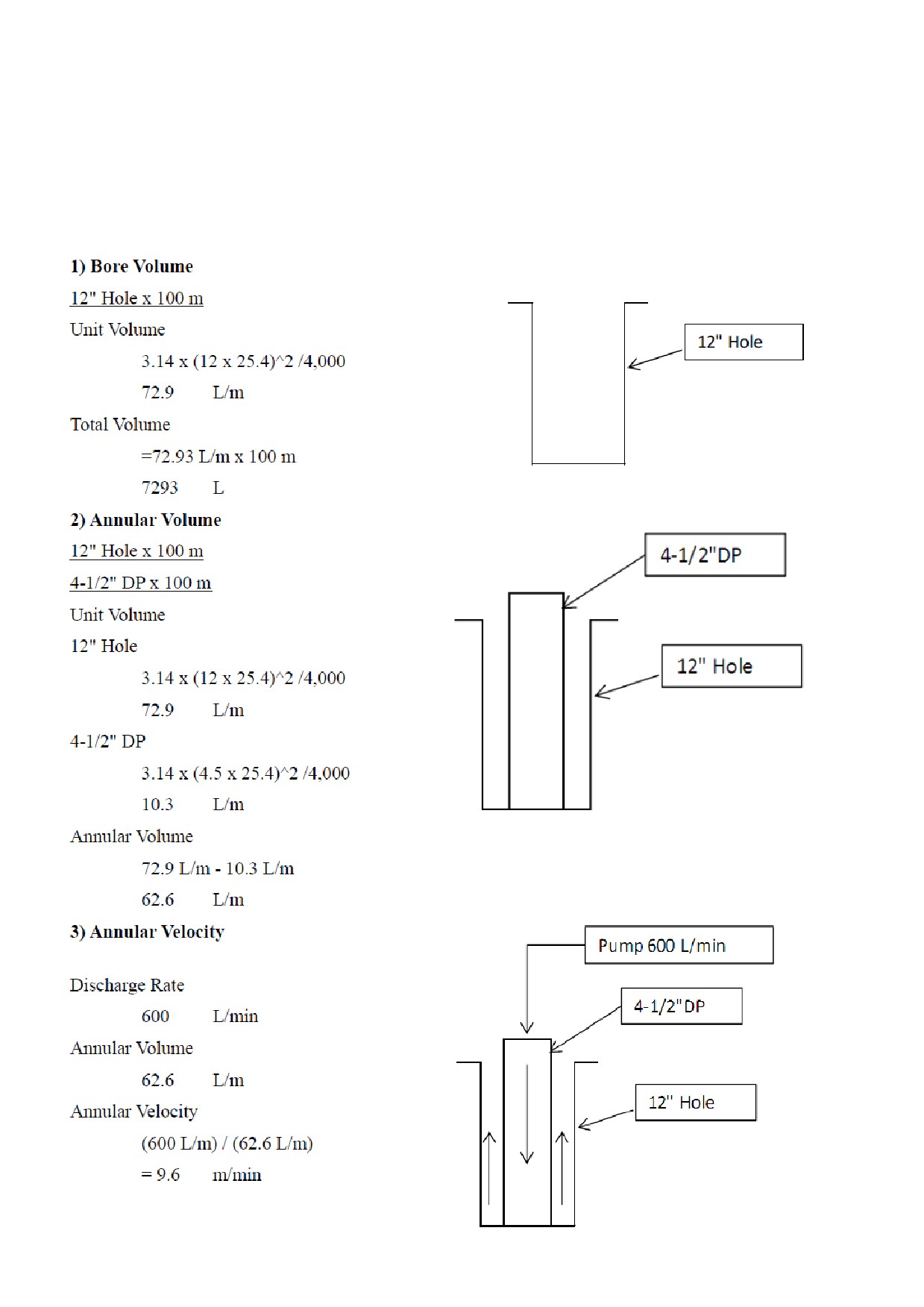
DDCAP Technical Manual for Drilling Works
For Technical Support Plan for the Drillers in DDCA
2.7.2 ANNULAR VOLUME AND VELOCITY
The calculation of annular volume and annular velocity is an indispensable knowledge to all
drillers for the proper drilling plan and control. The follows are an example of the calculation of
annular volume and annular velocity.
DDCAP Technical Manual for Drilling Works
For Technical Support Plan for the Drillers in DDCA
2.8 WEIGHT OF DRILLING TOOLS (TA CODE 2-8)
The elements of the drill string is described in Section 2-4 Rig Accessory of this manual. This
section explains how to express the drill string assembly and how to calculate the total weight of
the drill string.
2.8.1 DRILL STRING ASSEMBLY
Prior to the decision of drill string assembly, necessary tools shall be listed up with their capacities
before the determination of drill string assembly. Example of drill string assembly is shown in
Table 26, DP: Drill Pipe, DC: Drill Collar, ST: Stabilizer
Table 27 and Table 28. These examples are for the mud drilling of 2stages. The 1st stage is
drilling by 12-1/4” bit down to 30 m and the 2nd is drilling by 8-1/2” bit down to 100 m. At first,
necessary drilling tools for 12-1/4” drilling and 8-1/2” drilling shall be listed up as shown in Table
26. Then, the drill string assemblies are determined respectively for 12-1/4” drilling and 8-1/2”
drilling as shown in DP: Drill Pipe, DC: Drill Collar, ST: Stabilizer
Table 27 and Table 28.
Table 26 List of Necessary Tools for 12-1/4” and 8-1/2” Drilling
Connection
Unit Length
Tool
Top
Bottom
(m)
4-1/2" DP
3-1/2" IF Box
3-1/2" IF Pin
6
6-1/4" ST
4" IF Box
4" IF Pin
1.2
6-1/4" DC
4" IF Box
4" IF Pin
6
8-1/4" ST
6-5/8" Reg Box
6-5/8" Reg Pin
1.2
8-1/4" DC
6-5/8" Reg Box
6-5/8" Reg Pin
6
8-1/2" Tri-Cone Bit
4-1/2" Reg Pin
-
0.6
12-1/4" Tri-Cone Bit
6-5/8" Reg Pin
-
0.8
Crossover Sub
3-1/2" IF Box
6-5/8" Reg Pin
0.6
Bit Sub
6-5/8" Reg Box
6-5/8" Reg Box
0.6
DP: Drill Pipe, DC: Drill Collar, ST: Stabilizer
Table 27 Drill String Assembly for 12-1/4” x 30 m Drilling
Connection
Unit Length
Tool
Qty.
Length (m)
Top
Bottom
(m)
4-1/2" DP
3-1/2" IF Box
3-1/2" IF Pin
6
4
24
Crossover Sub
3-1/2" IF Box
6-5/8" Reg Pin
0.6
1
0.6
8-1/4" DC
6-5/8" Reg Box
6-5/8" Reg Pin
6
1
6
8-1/4" ST
6-5/8" Reg Box
6-5/8" Reg Pin
1.2
1
1.2
Sub
6-5/8" Reg Box
4-1/2"Reg Box
0.6
1
0.6
12-1/4" Tri-Cone Bit
6-5/8" Reg Pin
-
0.6
1
0.6
Total Length (m)
33
Table 28 Drill String Assembly for 8-1/2” x 100 m Drilling
Connection
Unit Length
Tool
Qty.
Length (m)
Top
Bottom
(m)
4-1/2" DP
3-1/2" IF Box
3-1/2" IF Pin
6
14
84
Crossover Sub
3-1/2" IF Box
4"IF Box
0.6
1
0.6
6-1/4" DC
4" IF Box
4" IF Pin
6
3
18
6-1/4" ST
4" IF Box
4" IF Pin
1.2
1
1.2
Bit Sub
4" IF Box
6-5/8" Reg Box
0.6
1
0.6
12-1/4" Tri-Cone Bit
6-5/8" Reg Pin
-
0.6
1
0.6
Total Length (m)
105
37

DDCAP Technical Manual for Drilling Works
For Technical Support Plan for the Drillers in DDCA
2.8.2 WEIGHT CALCULATION
Total weight of the drill string assemblies are calculated for each. The weights of bits, subs,
stabilizers can be included in those of driller pipes or drill collars, as they are not heavy comparing
to the total weight.
Table 29 Weight Calculation of Drill String Assembly for 12-1/4” x 30 m Drilling
Tool
Unit Weight (kg/m)
Length (m)
Weight (kg)
4-1/2" DP
27
27
729
8-1/4" DC
241
6
1,446
Total
33
2,175
Table 30 Weight Calculation of Drill String Assembly for 8-1/2” x 100 m Drilling
Tool
Unit Weight (kg/m)
Length (m)
Weight (kg)
4-1/2" DP
27
84
2,268
6-1/4" DC
125
21
2,625
Total
105
4,893
As a result, total weight is 2.2 tons for 12-1/4” drilling and 4.9 tons for 8-1/2” drilling. Therefore,
with the consideration of 10 % of the safety factor for the stucking, the lifting capacity of the
drilling rig shall be not less than 5.4 tons. Furthermore, the total weight of casing pipes shall be
considered as well.
38
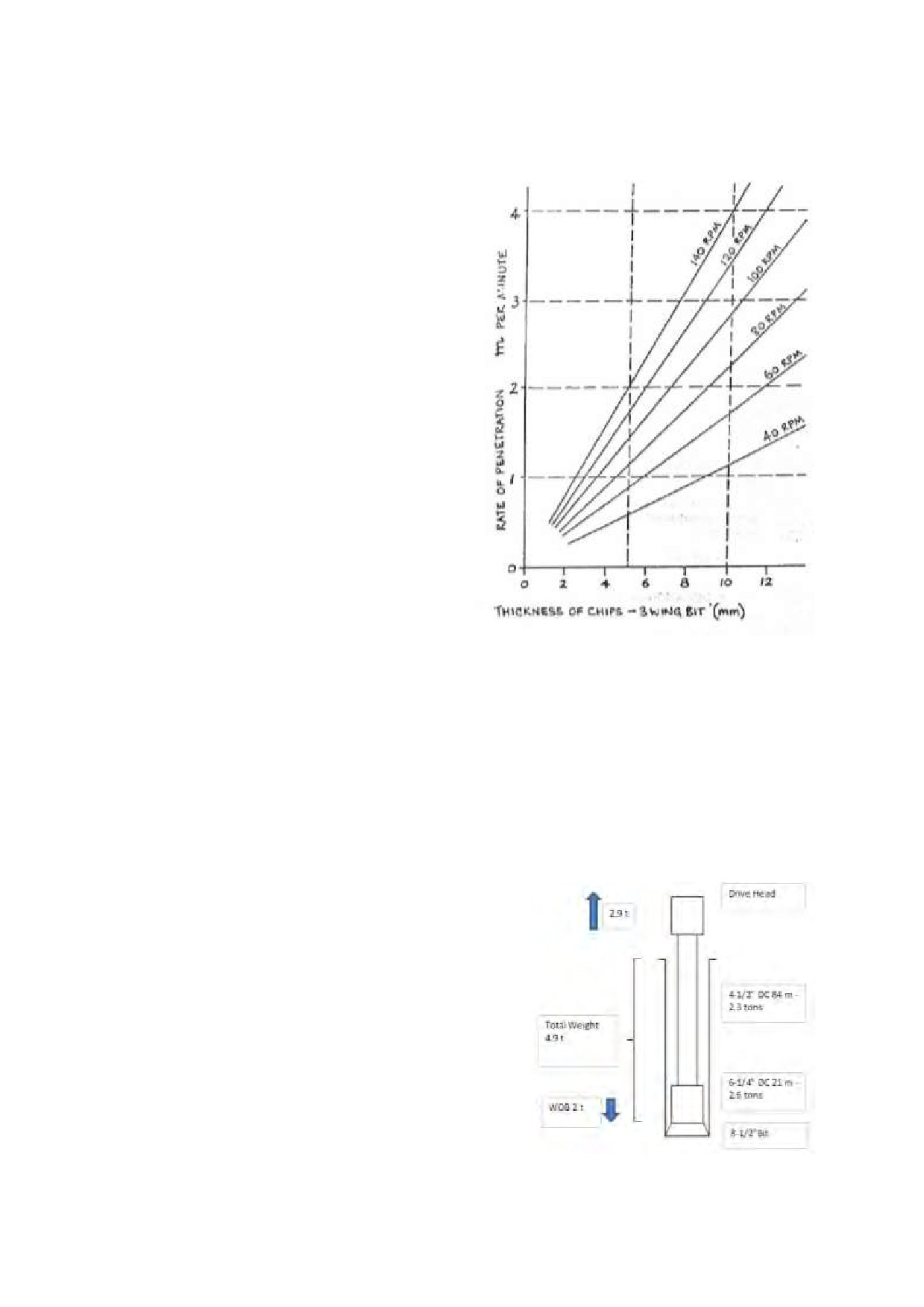
DDCAP Technical Manual for Drilling Works
For Technical Support Plan for the Drillers in DDCA
2.9 ROTARY BIT ROTATION SPEED AND WEGHT ON BIT (TA CODE 2-9)
2.9.1 ROTATION SPEED OF BIT
At the commencement of the hole, safe and
smooth rotation and feed rates must be aimed
for any consideration. When the hole is safely
collared and drilling is proceeding, smooth
operation continues to be the prime aim, but
while maintaining smooth operation, work to
achieve the desirable thrust loadings and
rotational speed to give correct chip making.
The chip size produced by a rotary bit is
controlled by four factors:
1. nature of the formation
2. the way that the bit makes the chip
(crushing, cutting, tearing etc)
3. rotary speed
4. penetration rate
Large chips measn better samples and less
energy required to penetrate. Larger chips
also make chip clearing more difficult.:
1. the formation
2. the drill string
Source: Australian Drilling Industry Training Committee Ltd
3. the interaction between these and the
Figure 17 Bit Penetration and Rotary
drilling rig
Speed
The penetration rate improves as we increase
thrust and rotation speed. But this holds true only while the bit operates correctly. If the bit is
overloaded or runs too fast, the bearings break down, the gauge cutters wear rapidly and the chip
clearing operation bogs down. For all bits, there is a maximum thrust and speed. For most bits,
there is a minimum thrust to make them penetrate correctly.
Figure 17 shows the relationship between bit penetration and rotary speed. However, in DDCA,
the range of 30 to 100 r.p.m is employed for the rotation speed of rotary bits.
2.9.2 WEIGHT ON BIT
The weight required on any rock roller bit for effective
and Maximum Efficient Rate of Penetration (MERP)
varies directly as the compressive strength of material
being cut. This is a broad statement which is bascally
true but within which there are many variations and
exceptions. The heavy weights necessary to drill hard
formations are required to give effective crushing force
to the bit tooh and probably to keep the tool more or
less flat running bottom.
The weight shall be loaded to to the bit when drilling
the hard formations. In general, maximum weight on
bit (WOB) is thought to be 1 to 1.5 tons per inch of bit
diameter. If a bit is of 8 inches, maximum WOB is
estimated to be eight to 12 tons. However, for the
drilling of the level of
150 m boreholes, WOB is
Figure 18 Example of the
Calculation of WOB
39
DDCAP Technical Manual for Drilling Works
For Technical Support Plan for the Drillers in DDCA
between the range of 1 to 3 tons. So as not to cause the damage of the drilling tools and the
deviation of the hole, the WOB shall be within the weight of drill collar. During drilling, WOB
shall be regulated by the lifting force by drive head.
Figure 18 shows an example of the calculation of the WOB for the drilling by 8-1/2” bit with 84 m
of 4-1/2” DPs and 21 m of 6-1/4” DCs. The WOB is calculated as the following:
Maximum Weight on Bit (WOB)
2.6 x 0.8 =
2.08
ton
Total Weight of Drill String
4.9
ton
Target WOB
2
ton
Lifting Load by Drive Head
4.9 - 2 = 2.9
ton
The maximum WOB shall be not more than 80 % of the weitght of DCs (2.6 tons), with the
consideration of the safety factor. Therefore, the target WOB was decided to be 2.0 tons. Total
weight of the drill string is 4.9 ton. In order to regulate the WOB to 2.0 tons, the drill string shall
be lifted up by the drive head. Then remaing weight of 2.9 tons are loaded on the bit as the WOB.
40
DDCAP Technical Manual for Drilling Works
For Technical Support Plan for the Drillers in DDCA
2.10 DTH BIT ROTATION SPEED AND WEGHT ON BIT (TA CODE 2-10)
2.10.1 ROTATION SPEED
To start drilling, turn on air rotary slowly. Then feed down slowly until the piston starts operating.
Add just enough pulldown pressure to start breaking rock. Make sure the bit does not drift when
it first strikes the formation because this can damage the bit buttons. Always check the operation
of a DTH tool before running it into a hole. Try it out first on a solid piece of timber at the
surface. As the tool approaches the bottom of the hole, proceed and start rotation before putting
weight on the bit. The presence of water in the hole when drilling is resumed will not prevent tool
operation. Lowering the tool into the hole with the air turned on will force the water out of the hole.
Proper rotation speed is important for long bit life and optimum penetration. The recommended
speed ranges from 12 to 40 r.p.m. A slower rotation is used in hard, abrasive formations. A
faster rotation is acceptable when drilling in soft, nonabrasive formations. Ideally, the bit should
penetrate about 10 mm (3/8 in) per drill pipe revolution.
“Rule of thumb” is penetration rate in
metres-per-hour x 1.6 to obtain r.p.m about one-half of the penetration rate in feet-per-hour (Adjust
up or down several r.p.m to match formation).
2.10.2 WEIGHT ON BIT
When the bit first cotacts the formation, apply minimal weight on the bit. After a few minutes,
increase the thrust pressure to allow the tool to run smoothly. The correct optimum weight should
be monitored and maintained throughout the drilling operation. As the hole gets deeper and drill
pipe is added, the thrust pressure must be reduced to compensate for the added weight of the drill
pipe. Hydraulic pressure required to keep the optimum weight on the bit varies from rig to rig.
Principally, whole totoal weight of the drill string shall be balanced by the drill head and WOB
shall be less than one ton, so as not to cause the hole deviation. However, WOB and drilling
speed shall be carefully regulated by the driller, so that the DTH can catch up the drilling down
speed.
41
DDCAP Technical Manual for Drilling Works
For Technical Support Plan for the Drillers in DDCA
3 DRILLING CONTROL (TA CODE 4)
3.1 MUD CONTROL (A CODE 4-1)
The roll of mud circulation is as follows:
Prevension from wall collapse
Removal of drill cuttings from the hole
Prevension from flow-in of groundwater
Prevension form lost circulation
Cleaning and cooling of bit
Reducing the friction of bit rotation
Bentonite is the most general mud stabilizer. Other mud additives are CMC, polimers and
dispersant. Viscosiity and density of the mud shall be well controlled by using the marsh funnel
and mud balance. Funnel spped shall be approximately 30 seconds and specific gravity shall be
not more than 1.2. If the mud is too strong, the cutting separation becomes non effective.
Furthermore, it may cause the stucking of the drill string. The separation work from the mud
canal is important.
Mud circulation system is composed of mud pump, suction pit, settlement pit and so on. Drillers
are required to understand the functions of each component and proper operation of the mud
circulation sysmte is important to implement the smooth drilling works. Figure 19 shows the
standard layout of drilling Figure 19equipment including the mud pits and canals.
Figure 19 Standard Layout of Drilling Equipment on Site
42
DDCAP Technical Manual for Drilling Works
For Technical Support Plan for the Drillers in DDCA
3.2 MUD PUMP OPERATION (TA CODE 4-2)
The discharge rate of mud pump is important for the removal of the drill cuttings. Usual cares
shall be taken on the worn out of the parts of the mud pump, because it decreases the discharge rate.
In case that the discharge rate decreases during drilling, drill string shall be raised up to the depth
up to the safe depth (in the casing) to check the mud pump.
The pump pressure shall be kept recorded as it is an important parameters to identify the borehole
conditions. The variation of the pump pressure indicates the following conditions:
Increase of the pressure:
Encountering clayey formations
Mud visicosity and/or density is elevated
Bore wall collapse
Drill cuttings remains in the hole
Bit is covered by the clay
According to the increase of depth
Decrease of the pressure:
Breakdown of the mud pump
Mud viscosity and/or density is decreased
Lost circulation
Encountering sandy formations
Please refer to Technical Item 2-4 for the further specifications and structure of the mud pump.
43

DDCAP Technical Manual for Drilling Works
For Technical Support Plan for the Drillers in DDCA
3.3 CASING FOR MUD DRILLING (TA CODE 4-3)
The boreholes in sedimentary formation are
normally drilled by mud drilling methods in
two stages, i.e. surface hole drilling and
production hole drilling.
Unlike DTH
drilling, conductor casing is not installed
unless collapsible and/or lost circulation
formation exists which shall be protected by
the conductor casing. Figure 20 shows an
example of the casing program for mud
drilling borehole of which production casing
and screen pipes are of 6”.
The surface casing is required when:
Surface water must be sealed off
Unstable formations interfere with
drilling, or
Artesian flows are possible. in this case
the surface casing must be cemented
The purpose of surface casing is to isolate
freshwater zones so that they are not contaminated during drilling and completion.
The surface
casing is also necessary for the smooth work around the borehole during the drilling.
PVC casing and screen pipes are used for most of the boreholes in Tanzania. Please refer
Technical Item 6-1 for the specifications of PVC casing and screens and Technical Item 6-3 for the
installation procedures.
44
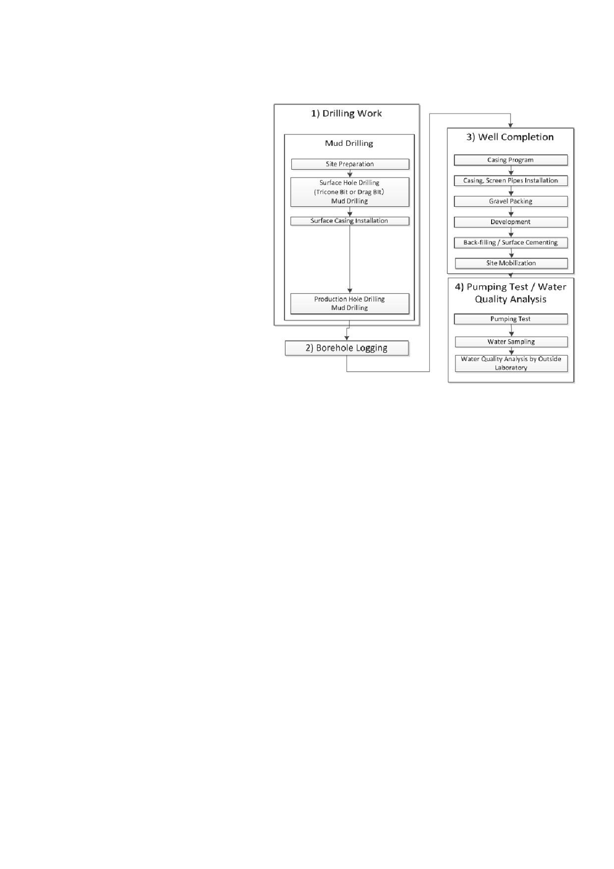
DDCAP Technical Manual for Drilling Works
For Technical Support Plan for the Drillers in DDCA
3.4 DRILLING OPERATION FOR MUD DRILLING (TA CODE 4-4)
Figure 20 shows the process of the
drilling works by mud drilling method.
It includes many processes and
drillers are required to acquire lots of
knowledge
and
techniques.
Technical Item 1 to 15 covers all the
process and drillers can refer to each
material to conduct the works.
DDCA has the report forms for the
record of the drilling works. Drillers
shall keep proper records of their
works using these forms. Figure 21
shows an example of well completion
form and Figure
22 is another
example of well section drawing.
Figure 20 Work Flow of Mud Drilling
45
//////////////////////////////////////////