DYNAPAC Vibratory roller CC224HF/324HF/384HF, CC2200/3200/3800, CC3800H. Instruction manual (2023) - page 1
Instruction manual
Operating & Maintenance
Vibratory roller
CC224HF/324HF/384HF
CC2200/3200/3800
CC3800H
Engine
Cummins QSB 3.3 (IIIA/T3)
Deutz TCD 3.6 L04 (IIIB/T4i), (IIIB/T4f)
Deutz TCD 3.6 L04 (stage V)
Serial number
10000311xxA009344 -
10000315xxA009393 -
10000319xxA009520 -
10000336xxA012872 - 25714
10000340xxA010700 - 23272
10000344xxA012937 - 17508
10000423xxA020964 -
10000427xxA021816 -
10000439xxA023043 -
10000456xxA025046 -
10000460xxA030824 -
Translation of original instruction
Reservation for changes
Printed in Sweden
Table of Contents
Introduction
1
The machine
1
Intended use
1
Signal symbols and meaning
1
Safety information
1
General
2
CE marking and Declaration of conformity
3
Safety - General instructions
5
Safety - when operating
7
Driving near edges
7
Work driving
8
Safety (Optional)
9
Air conditioning
9
Edge cutter/compactor
9
Working lights - Xenon
10
Chip spreader
11
Special instructions
13
Standard lubricants and other recommended oils and fluids
13
Higher ambient temperatures,
above +40°C (104°F)
13
Lower ambient temperature - Freeze risk
13
Temperatures
13
High pressure cleaning
14
Fire fighting
14
Roll Over Protective Structure (ROPS), ROPS approved cab
14
Battery handling
14
Jump starting (24V)
15
Technical specifications
17
Vibrations - Operator station
17
Noise level
17
Electrical system
17
Slopes
17
Dimensions, side view
18
Dimensions, top view
19
Weights and volumes
20
Working capacity
20
General
22
CO2-emission
22
Hydraulic system
23
Air Conditioning / Automatic Climate Control (ACC) (Optional)
23
Technical data, Chip Spreader (Optional)
24
Tightening torque
25
Machine description
27
Diesel engine
27
Electrical system
27
Propulsion system
27
Brake system
28
Steering system
28
Vibration system
28
Cab
29
ROPS
29
Identification
30
Product and component plates
30
Product identification number on the frame
30
Machine plate
31
Explanation of 17PIN serial number
31
Engine plates
32
Decals
33
Location - decals
33
Location - decals, chip spreader (Optional)
34
Location - decals, CALIFORNIA
34
Safety decals
34
Info decals
38
Instruments/Controls
39
Control panel and controls
39
Function descriptions
40
Forward & Reverse lever
44
Function descriptions
44
Forward & Reverse lever
45
Function descriptions
45
Display explanations
45
Machine alarm
48
"MAIN MENU"
51
"USER SETTINGS"
52
"MACHINE SETTINGS"
53
Diesel engine (Stage V)
53
"EXHAUST CLEANING"
53
"SERVICE MENU"
54
"ABOUT"
55
Operator help when starting
56
Operator help Workmode
56
Instruments and controls, cab
57
Function description of instruments and controls in the cab
58
Using the cab controls
59
Defroster
59
Heat
59
AC/ACC
59
Electrical system (version 1)
60
Fuse boxes in main switchbox
60
Electrical system (version 2)
61
Fuse card in main switchbox
61
Power in engine compartment/battery compartment
62
Main fuse panel (Cummins)
62
Fuse box at master switch (Deutz)
63
Fuses in cab
64
Operation
65
Before starting
65
Master switch - Switching on
65
Control panel, adjustments
65
Operator's seat - Adjustment
66
Belt reminder
66
Operator's seat, comfort - Adjustments
67
Parking brake
67
Display - Control
68
Interlock
69
Operator position
70
View
70
Starting
71
Starting the engine
71
Display when activating choice via the button set
72
Alarm descriptions
73
Driving
73
Operating the roller
73
Interlock/Emergency stop/Parking brake - Check
75
Pivotal steering (Optional)
76
Burnout of DPF-filter (Regeneration) - (stage V)
77
DPF displays
77
Edge cutting (Optional)
79
Chip spreader (optional)
80
Adjusting the feed volume
80
Preparations before dismantling/assembly
83
Vibration
84
Manual/Automatic vibration
84
Manual vibration - Switching on
85
Amplitude/frequency - Changeover
85
Braking
85
Normal braking
85
Emergency braking
86
Switching off
86
Parking
87
Chocking the drums
87
Master switch
87
Long-term parking
89
Engine
89
Battery
89
Air cleaner, exhaust pipe
89
Watering system
89
Fuel tank
89
Hydraulic reservoir
89
Hoods, tarpaulin
90
Steering cylinder, hinges, etc
90
Miscellaneous
91
Lifting
91
Locking the articulation
91
Lifting the roller
92
Lifting the roller with jack:
92
Unlocking the articulation
93
Towing/Recovering
93
Short distance towing with the engine running
94
Short distance towing when the engine is inoperative
95
Towing the roller
95
Trailer eye
96
Transport
96
Loading CC224-624, CC2200-6200, CO2200
97
Operating instructions - Summary
99
Preventive maintenance
101
Acceptance and delivery inspection
101
Warranty
101
Maintenance - Lubricants and symbols
103
Maintenance symbols
104
Maintenance - Maintenance schedule
105
Service and maintenance points
105
General
105
Every 10 hours of operation (Daily)
106
After the FIRST 50 hours of operation
106
Every 50 hours of operation (Weekly)
107
Every 250 hours of operation (Monthly)
107
Every 500/1500 hours of operation
108
Every 1000 hours of operation (Every six months)
108
Every 2000 hours of operation
109
Maintenance, 10h
111
Diesel engine - Check oil level
111
Coolant level - Check
112
Fuel tank - Refueling
112
Water tank, Std - Filling
113
Hydraulic reservoir - Check fluid level
113
Sprinkler system/Drum
Check
114
Cleaning the coarse filter
114
Sprinkler system/Drum
Cleaning of sprinkler nozzle
115
Emergency watering (Accessory) - Extra pump in pump system
116
Scrapers, spring-action
Check
116
Scrapers
Setting - Adjustment
117
Maintenance - 50h
119
Fuel filter - Draining
119
Drum gear - Checking the oil level
120
Maintenance measures - 250 h
121
Diesel engine
Oil change
121
Engine
Replacing oil filter
122
Hydraulic fluid cooler
Checking - Cleaning
122
Battery
- Check condition
123
Air conditioning (Optional)
- Inspection
123
Air conditioning (Optional)
Drying filter - Inspection
124
Edge cutter (Optional)
- Lubrication
124
Maintenance measures - 500 h
125
Diesel engine
Oil change
125
Engine
Replacing oil filter
126
The engine fuel filter - replacement/cleaning
126
Hydraulic fluid cooler
Checking - Cleaning
127
Battery
- Check condition
127
Air cleaner
Checking - Change the main air filter
128
Backup filter - Change
128
Air cleaner
- Cleaning
129
Drum - oil level
Inspection - filling
129
Rubber elements and attachment screws
Check
130
Seat bearing - Lubrication
130
Pivot bearing (Optional) - Lubrication
131
Hydraulic reservoir cap - Check
131
Air conditioning (Optional)
- Inspection
132
Air conditioning (Optional)
Drying filter - Inspection
132
Edge cutter (Optional)
- Lubrication
133
Maintenance - 1000h
135
Diesel engine
Oil change
135
Engine
Replacing oil filter
136
The engine fuel filter - replacement/cleaning
136
Hydraulic fluid cooler
Checking - Cleaning
137
Battery
- Check condition
137
Air cleaner
Checking - Change the main air filter
138
Backup filter - Change
138
Air cleaner
- Cleaning
139
Hydraulic filter
Change
140
Drum - Oil change
141
Drum gear - Oil change
141
Drum gear - Checking the oil level
142
Rubber elements and attachment screws
Check
142
Seat bearing - Lubrication
143
Pivot bearing (Optional) - Lubrication
143
Hydraulic reservoir cap - Check
144
Steering hitch - Tightening
144
Cab
Fresh air filter - Replacing
145
Air conditioning (Optional)
- Overhaul
145
Air conditioning (Optional)
Drying filter - Inspection
146
Edge cutter (Optional)
- Lubrication
146
Maintenance - 2000h
147
Diesel engine
Oil change
147
Engine
Replacing oil filter
148
The engine fuel filter - replacement/cleaning
148
Hydraulic fluid cooler
Checking - Cleaning
149
Battery
- Check condition
149
Air cleaner
Checking - Change the main air filter
150
Backup filter - Change
150
Air cleaner
- Cleaning
151
Hydraulic filter
Change
152
Drum - Oil change
153
Drum gear - Oil change
153
Drum gear - Checking the oil level
154
Rubber elements and attachment screws
Check
154
Seat bearing - Lubrication
155
Pivot bearing (Optional) - Lubrication
155
Hydraulic reservoir cap - Check
156
Hydraulic reservoir
Fluid change
156
Fuel tank
- Cleaning
157
Watering system
- Draining
157
Water tank - Cleaning
158
Steering joint - Check
158
Steering hitch - Tightening
159
Cab
Fresh air filter - Replacing
159
Air conditioning (Optional)
- Overhaul
160
Air conditioning (Optional)
Drying filter - Inspection
160
Edge cutter (Optional)
- Lubrication
161
Introduction
Introduction
The machine
Dynapac CC224HF/324HF/384HF,
CC2200/3200/3800 are models of vibratory tandem
rollers in 8/8/9.5 metric tonnes class featuring
1500/1730/1730 mm (59/68/68 in) wide drums. The
machines are equipped with drive, brakes, vibration
and timer for water sprinkler on both drums.
CC224HF/324HF, CC2200/3200 is also available as
Combi with four rubber wheels at rear replacing the
steel drum.
A variety of different engine power settings, operator
platforms, control possibilities and options makes the
machine available in a lot of different configurations.
Intended use
The machine is mainly designed to be used for thin
and thick asphalt layers with regards to dual vibration
amplitudes that are optimized for this purpose. It is
also possible to compact granular soil material, such
as sand and gravel.
Signal symbols and meaning
WARNING ! Indicates potential hazardous
situation/procedure which, if not avoided, could
result in death or serious injury.
CAUTION ! Indicates potential hazardous
situation/procedure which, if not avoided, could
result in minor or moderate injury, damage to
the machine or property.
Safety information
It is recommended to at least train operators in
handling and daily maintenance of the machine
in accordance with the instruction manual.
Passengers are not allowed on the machine,
and you must sit in the seat when operating the
machine.
The safety manual supplied with the machine
must be read by all roller operators. Always
follow the safety instructions. Do not remove
the manual from the machine.
1
Introduction
We recommend that the operator reads the
safety instructions in this manual carefully.
Always follow the safety instructions. Ensure
that this manual is always easily accessible.
Read the entire manual before starting
the machine and before carrying out
any maintenance.
Replace immediately the instruction manuals if
lost, damaged or unreadable.
Ensure good ventilation (extraction of air by fan)
where the engine is run indoors.
CALIFORNIA
Proposition 65
Decal and location of decal shown in section
Machine description.
General
This manual contains instructions for machine
operation and maintenance.
The machine must be correctly maintained for
maximal performance.
The machine should be kept clean so that any
leakages, loose bolts and loose connections are
discovered at as early a point in time as possible.
2
Introduction
Inspect the machine every day, before starting.
Inspect the entire machine so that any leakages or
other faults are detected.
Check the ground under the machine. Leakages are
more easily detected on the ground than on the
machine itself.
If faults or suspected damage are detected on the
roller, contact the responsible supervisor for any action.
THINK ENVIRONMENT ! Do not release oil,
fuel and other environmentally hazardous
substances into the environment. Always send
used filters, drain oil and fuel remnants to
environmentally correct disposal.
This manual contains instructions for periodic
maintenance, where maintenance after every
10 and 50 hours of operation can be performed
by the machine operator. Other maintenance
intervals must be carried out by accredited
(Dynapac) service personnel.
Additional instructions for the engine can be
found in the manufacturer's engine manual.
Specific maintenance and checks on diesel
engines must be performed by engine supplier
authorized personnel.
CE marking and Declaration of conformity
(Applies to machines marketed in EU/EEC)
This machine is CE marked. This shows that on
delivery it complies with the basic health and safety
directives applicable for the machine in accordance
with machinery directive 2006/42/EC and that it also
complies with other regulations and directives
applicable for this machine.
A "Declaration of conformity" is supplied with this
machine, which specifies the applicable regulations
and directives with supplements, as well as the
harmonized standards and other regulations that are
applied and according to the regulations must be
declared in writing.
3
Introduction
4
Safety - General instructions
Safety - General instructions
(Also read the safety manual)
•
The operator must be familiar with the contents of the OPERATION section
before starting the roller.
•
Ensure that all instructions in the MAINTENANCE section are followed.
•
Only the operator is allowed to be on the roller. Remain seated at all times
when operating the roller.
•
Never use the roller if it is in need of adjustment or repair.
•
Only ascend and descend the roller when it is stationary. Use the intended
footsteps, grips and rails. Always use the three-point grip (both feet and one
hand, or one foot and both hands) when ascending or descending the
machine. Never jump down from the machine.
•
Dynapac always recommends mounted ROPS (Roll Over Protective
Structure), or a ROPS-approved cab and seat belt usage.
•
Drive slowly in sharp bends.
•
Avoid driving across slopes. Drive straight up or straight down the slope.
•
Never operate with the drum outside the edge, the substrate might not have
full bearing strength or the edge is close to a slope. Avoid operating close to
edges and ditches and the like as well as on poor ground conditions that
jeopardizes the bearing strength and capacity to support the roller.
•
Make sure that there are no obstacles in the direction of travel, on the
ground, in front of or behind the roller, or overhead.
•
Drive particularly carefully on uneven ground.
•
Keep the roller clean. Clean any dirt or grease that accumulates on the
footsteps or operator platform to avoid slipping risk. Keep all signs and
decals clean and legible.
•
Safety measures before refueling:
- Stop the engine
- Do not smoke.
- No naked flames in the vicinity of the roller.
- Earth the filling equipment nozzle by keeping it in contact to the tank
opening to avoid sparks.
•
Before repairs or service:
- Chock the drums/wheels.
- Lock the articulation if necessary.
- Place blocks under overhanging equipment, such as strike-off blade, edge
cutter/compactor and chip spreader.
5
Safety - General instructions
•
Hearing protection is recommended if the noise level exceeds 80 dB(A). The
noise level can vary depending on the equipment on the machine and the
surface the machine is being used on.
•
Modifications to the roller, including the use of any attachment/equipment,
not approved by Dynapac that might compromise safety (including visibility)
are not allowed. Any modifications are only to be made after written approval
has been given by Dynapac.
•
Avoid using the roller before the hydraulic fluid has reached its normal
working temperature. Braking distances can be longer than normal when the
fluid is cold.
•
For your own protection always wear:
- working boots with steel toecaps
- ear protectors
- reflecting clothing/high visibility jacket
Also wear:
- helmet if no cab or FOPS, or if required by worksite management
- working gloves if no cab and for work outside operator´s platform.
•
If the machine seems to be responding abnormally during travel, stop and
check it.
6
Safety - when operating
Safety - when operating
Prevent persons from entering or remaining in
the risk zone, i.e. a distance of at least 7 m (23
ft) in all directions from operating machines.
The operator may allow a person to remain in
the risk zone, however he/she must be attentive
and operate the machine only when the person
is fully visible or has given a clear indication of
where he or she is.
Avoid driving across a slope. Drive straight up
and down sloping ground.
Driving near edges
Never operate with the drum outside the edge, the
substrate might not have full bearing strength or
the edge is close to a slope.
Keep in mind that the machine's center of gravity
moves outwards when steering. For example, the
center of gravity moves to the right when you steer
to the left.
7
Safety - when operating
Work driving
To exit the cab in an emergency, release the
hammer on the rear right post and break the rear
window.
Dynapac always recommends mounted ROPS
(Roll Over Protective Structure), or a
ROPS-approved cab and seat belt usage.
Avoid operating close to edges and ditches and the
like as well as on poor ground conditions that
jeopardizes the bearing strength and capacity to
support the roller. Pay attention to potential obstacles
above the machine, such as overhead cables and the
branches of trees etc.
Pay particular attention to the stability of the substrate
when compacting close to edges and holes. Do not
compact with a large overlap from the previous track in
order to maintain roller stability. Consider other
compaction methods such as remote-control or a
walk-behind roller close to steep slopes or where the
bearing strength of the substrate is unknown.
8
Safety (Optional)
Safety (Optional)
Air conditioning
The system contains pressurized refrigerant. It is
forbidden to release refrigerants into the
atmosphere.
Work on the refrigerant circuit is only to be carried
out by authorized companies.
The cooling system is pressurized. Incorrect
handling can result in serious personal injury. Do
not disconnect or undo the hose couplings.
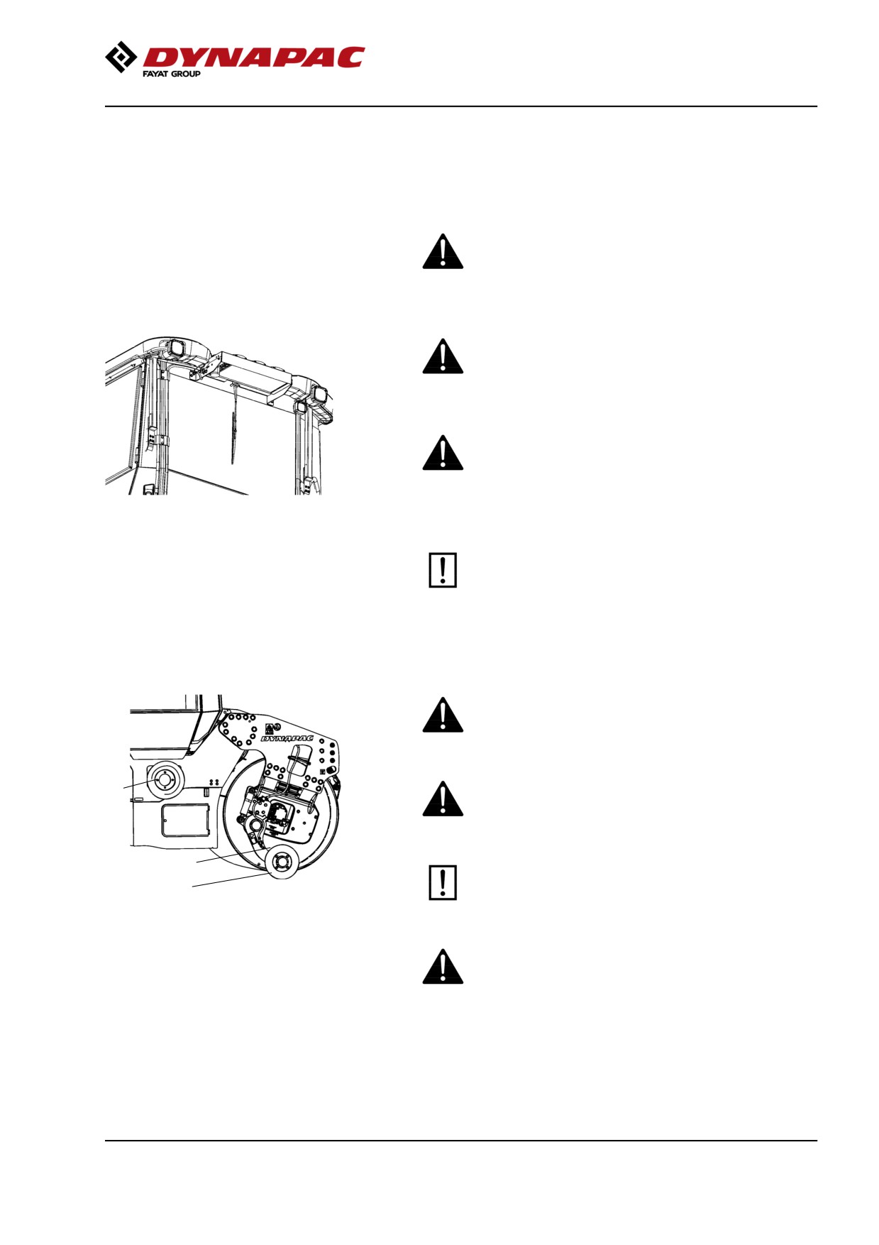
Fig. Air conditioning (ACC)
The system must be re-filled with an approved
refrigerant by authorized personnel when
necessary. See decal on or in the vicinity of the
installation.
Edge cutter/compactor
The operator must make sure that nobody is in the
area of operation while the machine is in use.
The edge cutter consists of rotating components
3
and there is a risk of being crushed.
1
The tool must be returned to the transport
2
position (raised position) (1) every time it has
been used.
Fig. Edge cutter/compactor
1. Transport position
2. Operating position
3. Holder for cutter/compactor wheel.
If the edge cutter and its parts are dismantled,
make sure that it is set in a relieved position and
resting on the ground.
9
Safety (Optional)
Working lights - Xenon
Warning, high voltage!
The working lights of the Xenon type have a
secondary high-voltage source.
Work on the lighting should only be conducted by an
authorized electrician and with the primary voltage
disconnected.
Contact a Dynapac dealer!
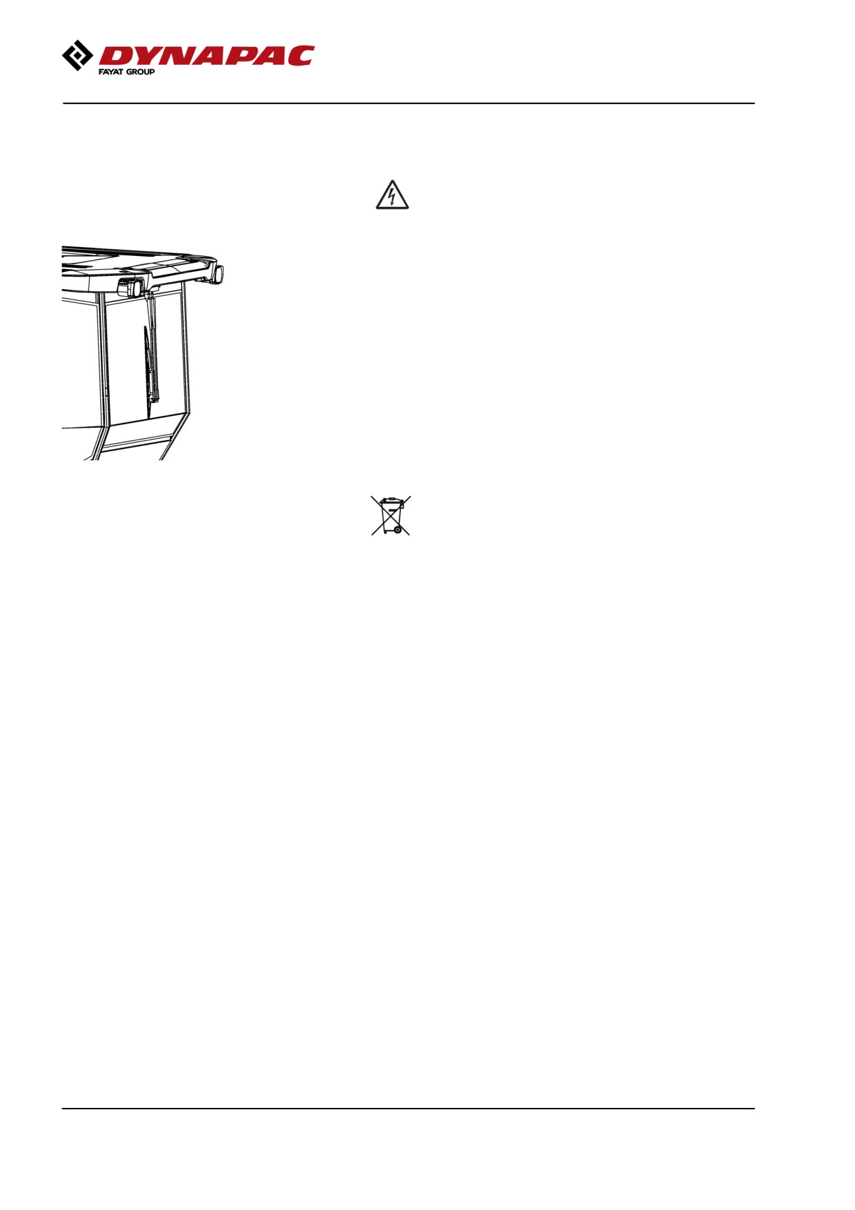
Figure. Xenon lighting on cab
Warning, environmentally hazardous waste!
Working lights of the Xenon type include a discharge
lamp that contains mercury (Hg).
A defective lamp is to be considered as hazardous
waste and shall be disposed off as per local directives.
10
Safety (Optional)
Chip spreader
The machine must not be transported with chip in
the chip spreader. The weight for the chip
spreader is noted on the sign plate of the unit. This
weight is not included in the machine weight noted
on the lift plate.
The operator must make sure that nobody is in
the area of operation while the machine is in
use.
Risk of crushing and pinch injuries. The chip
spreader has rotating parts.
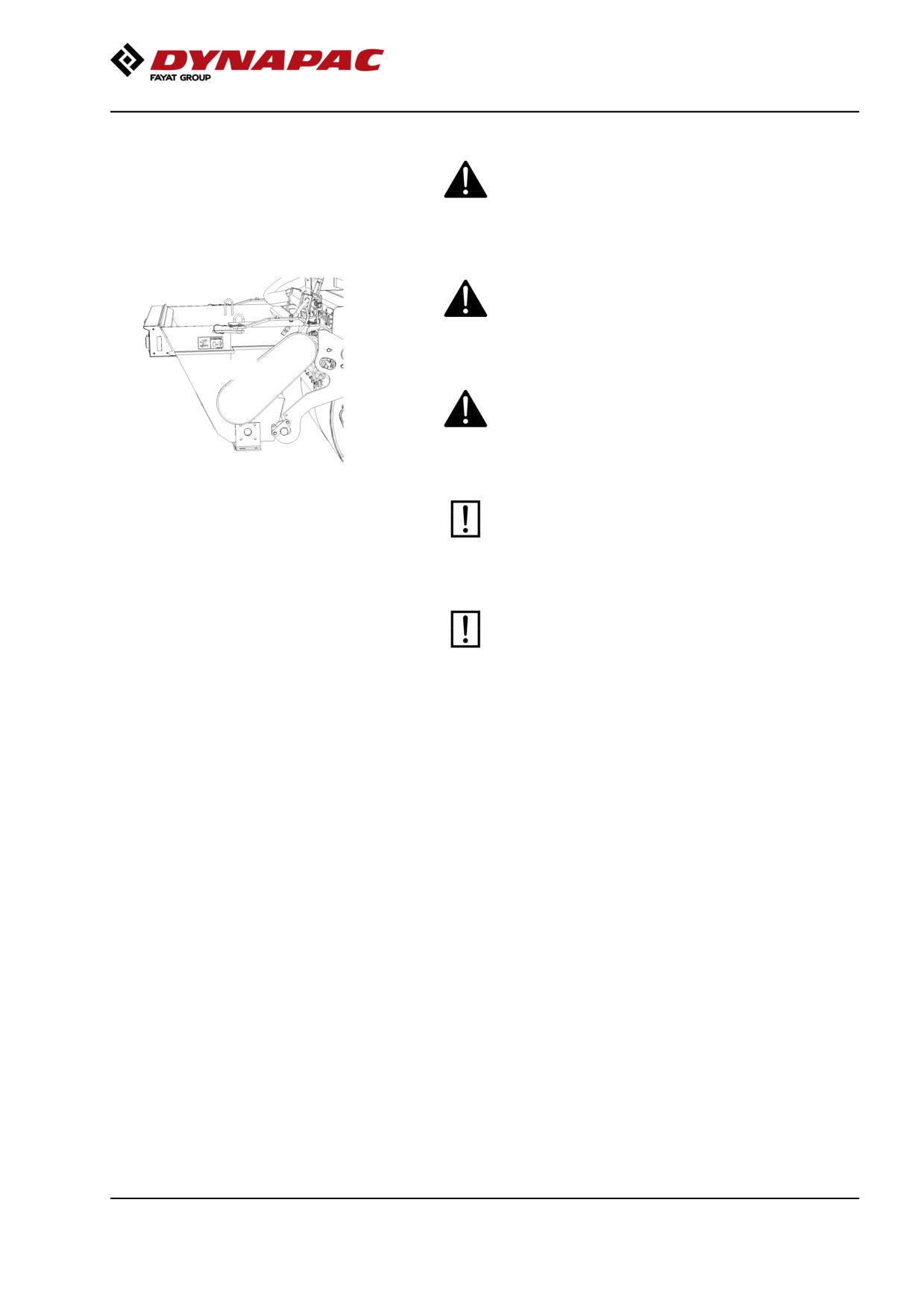
Fig. Chip spreader
The chip spreader must be reset in transport
mode after it has been used.
Fitting the chip spreader changes the total length
of the machine.
11
Safety (Optional)
12
Special instructions
Special instructions
Standard lubricants and other recommended
oils and fluids
Before leaving the factory, the systems and
components are filled with the oils and fluids specified
in the lubricant specification. These are suitable for
ambient temperatures in the range -15°C to +40°C
(5°F - 105°F).
The maximum ambient temperature for
biodegradable hydraulic oil is +35°C (95°F).
Higher ambient temperatures,
above +40°C (104°F)
For operation of the machine at higher ambient
temperatures, however maximum +50°C (122°F), the
following recommendations apply:
The diesel engine can be run at this temperature using
normal oil. However, the following fluids must be used
for other components:
Hydraulic system - mineral oil Shell Tellus S2V100
or similar.
Lower ambient temperature - Freeze risk
Make sure that the watering system is empty/drained
of water (sprinkler, hoses, tank/s) or that anti-freeze
has been added, to prevent the system freezing.
The outlet hose from the central tank can be
disconnected and the end placed in a container with
antifreeze to run this through the pump/filter.
Temperatures
The temperature limits apply to standard versions
of rollers.
Rollers equipped with additional equipment, such as
noise suppression, may need to be more carefully
monitored in the higher temperature ranges.
13
Special instructions
High pressure cleaning
Do not spray directly onto electrical components.
Do not use high pressure cleaning for
dashboard/display.
The Electrical Drive Control and the computer
box may not be washed with high pressure
cleaning and not at all with water. Clean them
with a dry wiper.
Detergent that can destroy electrical parts, or
which is conductive, must not be used.
Place a plastic bag over the fuel filler cap and secure
with a rubber band. This is to avoid high pressure
water entering the vent hole in the filler cap. This could
cause malfunctions, such as the blocking of filters.
Never aim the water jet directly at the fuel tank
cap, or into exhaust pipe. This is particularly
important when using a high-pressure cleaner.
Fire fighting
If the machine catches fire, use an ABC-class powder
fire extinguisher.
A BE-class carbon dioxide fire extinguisher can also
be used.
Roll Over Protective Structure (ROPS), ROPS
approved cab
If the machine is fitted with a Roll Over
Protective Structure (ROPS, or ROPS approved
cab) never carry out any welding or drilling in
the structure or cab.
Never attempt to repair a damaged ROPS
structure or ROPS structure in cab. These must
be replaced with new ROPS structure or new
cab.
Battery handling
When removing batteries, always disconnect the
negative cable first.
14
Special instructions
When fitting batteries, always connect the
positive cable first.
Dispose of old batteries in an environmentally
friendly way. Batteries contain toxic lead.
Do not use a quick-charger for charging the
battery. This may shorten battery life.
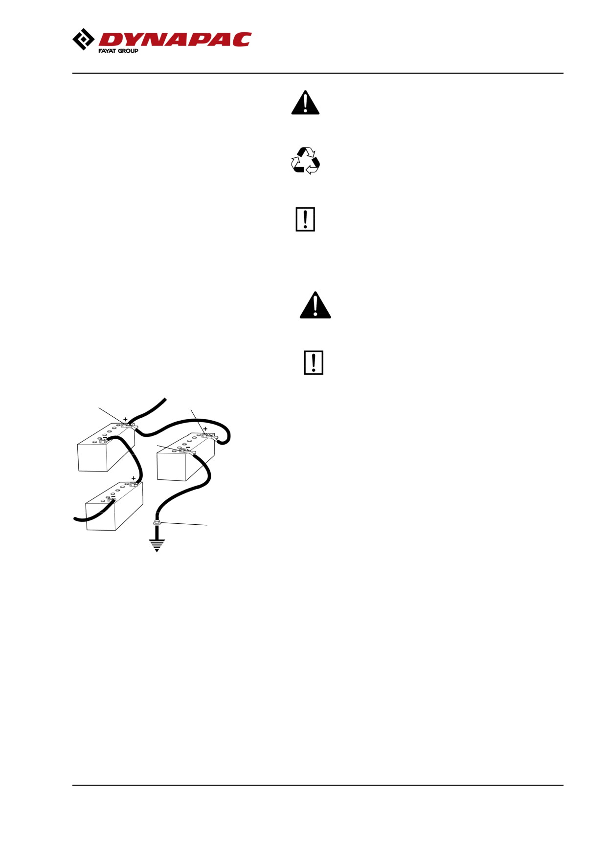
Jump starting (24V)
Do not connect the negative cable to the
negative terminal on the dead battery. A spark
can ignite the oxy-hydrogen gas formed
around the battery.
Check that the battery used for jump starting
has the same voltage as the dead battery.
2
1
Turn the ignition and all power consuming equipment
off. Switch off the engine on the machine which is
12V
providing jump start power.
3
Jump leads must have 24V.
24V
First connect the jump start battery's positive terminal
(1) to the flat battery's positive terminal (2).Then
12V
connect the jump start battery's negative terminal (3)
to, for example, a bolt (4) or the lifjting eye on the
machine with the flat battery.
4
Start the engine on the power providing machine. Let it
run for a while. Now try to start the other machine.
Disconnect the cables in the reverse order.
Fig. Jump starting
15
Special instructions
16
Technical specifications
Technical specifications
Vibrations - Operator station
(ISO 2631)
The vibration levels are measured in accordance with the operational cycle described in
EU directive 2000/14/EC on machines equipped for the EU market, with vibration switched
on, on soft polymer material and with the operator’s seat in the transport position.
Measured whole-body vibrations are below the action value of 0.5 m/s² as specified in Directive
2002/44/EC. (Limit is 1.15 m/s²)
Measured hand/arm vibrations also were below the action level of 2.5 m/s² specified in the same
directive. (Limit is 5 m/s²)
Noise level
The noise level is measured in accordance with the operational cycle described in
EU directive 2000/14/EC on machines equipped for the EU market, on soft polymer
material with vibration switched on and the operator's seat in the transport position.
Guaranteed sound power level, LwA
55/60kW
106 dB (A)
74/75kW
107 dB (A)
Sound pressure level at the operator's ear (platform), LpA
91 ±3 dB (A)
Sound pressure level at the operator's ear (cab), LpA
85 ±3 dB (A)
During operation the above values may differ because
of the actual operational conditions.
Electrical system
Machines are EMC tested in accordance with EN
13309:2000 'Construction machinery'
Slopes
The recommended max slope angle is for a machine
that runs straight on hard, flat surface.
Unstable ground, vibration on, speed and steering the
Max 20° or 36%
machine can all cause the machine to topple at
smaller angles than specified here.
17
Technical specifications
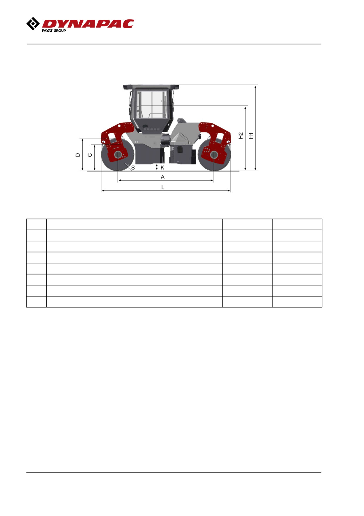
Dimensions, side view
Dimensions
mm
in
A
Wheel base
3340
131
D
Diameter, drum
1150
45
H1
Height, with ROPS/cab
2990
118
H2
Height, without ROPS/cab
2275
90
K
Ground clearance
310
12
L
Length, standard variant
4490
177
S
Thickness, drum amplitude, Nominal
18
0.7
18
Technical specifications
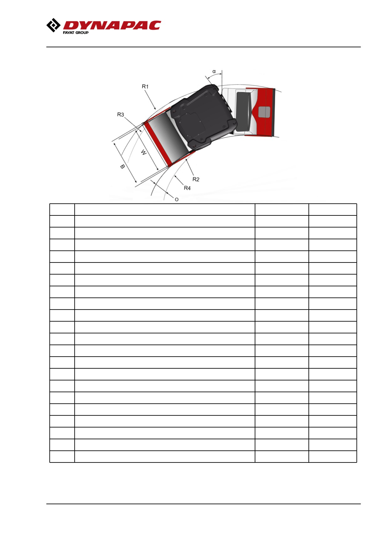
Dimensions, top view
Dimensions
mm
in
B1
Machine width, standard
CC224HF, CC2200
1640
64.5
CC324HF/384HF, CC3200/3800
1870
74
CC3800H
2020
79.5
B2
Machine width, asymmetrical
CC224HF, CC2200
1900
75
CC324HF, CC3200
2010
79
CC384HF, CC3800
2045
80.5
CC3800H
2085
82
R1
Turning radius, outer
CC224HF, CC2200
6570 / 5190*
259 / 204*
CC324HF, CC3200
6685 / 5305*
263 / 209*
CC384HF, CC3800
6685
263
R2
Turning radius, inner
CC224HF, CC2200
5570 / 3225*
219 / 127*
CC324HF, CC3200
-
-
CC384HF, CC3800
-
-
W
Drum width
CC224HF, CC2200
1500
59
CC324HF/384HF, CC3200/3800
1730
68
*) with offset
19
Technical specifications
Weights and volumes
Weights
Service weight
ROPS
Cab
(EN500)
CC224HF, CC2200
STD
(kg)
7 600
7 800
(lbs)
16 760
17 200
OFFSET
(kg)
8 100
8 300
(lbs)
17 860
18 300
CC324HF, CC3200
STD
(kg)
8 100
8 300
(lbs)
17 860
18 300
OFFSET
(kg)
8 600
8 900
(lbs)
18 960
19 630
CC384HF, CC3800
STD
(kg)
9 400
9 600
(lbs)
20 730
21 170
CC3800H
STD
(kg)
9 800
10 000
(lbs)
21 600
22 050
Fluid volumes
Fuel tank
130 liters
34 gal
Water tank
750 liters
198 gal
Working capacity
Compaction data
Static linear load
(Front)
(Rear)
CC224HF, CC2200
25,7
25,7
(kg/cm)
144
144
(pli)
CC324HF, CC3200
23,6
23,6
(kg/cm)
132
132
(pli)
CC384HF, CC3800
27,2
27,2
(kg/cm)
152
152
(pli)
CC3800H
28,9
28,9
(kg/cm)
162
162
(pli)
20
Technical specifications
Amplitude
High
Low
Low(CE-2006)
CC224HF-384HF,
0,7
0,3
0,2 (mm)
CC2200-3800
0.028
0.012
0.008
(in)
CC3800H
0,6
0,3
(mm)
0.024
0.012
(in)
Vibration frequency
High
High
Low
Low
amplitude
amplitude
amplitude
amplitude
(CE-2006)
(CE-2006)
48
48
67
61
(Hz)
2 850
2 850
4 020
3 660
(vpm)
Centrifugal force
High
High
Low
Low
amplitude
amplitude
amplitude
amplitude
(CE-2006)
(CE-2006)
CC224HF, CC2200
78
72
67
38
(kN)
17 550
16 200
15 075
8 550
(lb)
CC324HF/384HF,
90
77
75
43
(kN)
CC3200/3800
20 250
17 325
16 875
9 675
(lb)
Propulsion
Speed range
0-12 km/h
0-7.5 mph
Climbing capacity (theoretical)
CC224HF, CC2200
42 %
CC324HF/384HF,
37 %
CC3200/3800
CC3800H
31 %
21
Technical specifications
General
Engine
Manufacturer/Model
Cummins QSB 3.3
(IIIA/T3)
Deutz TCD 3.6 L04
(IIIB/T4i), (IIIB/T4f)
Deutz TCD 3.6 L04
(stage V)
Power output (SAE J1995), 2200 rpm
60kW (IIIA/T3)
80hp
74kW (IIIA/T3)
99hp
75kW (IIIB/T4i)
100hp
55kW (IIIB/T4f)
74hp
55kW (stage V)
74hp
Engine speed
- idling
900 rpm
- loading/unloading
1600 rpm
- work/transport
2 200 rpm
Tier4i / T4f / Stage IIIB / Stage V engines require the use of Ultra Low Sulphur Diesel
(ULSD) fuel, which has a sulphur content of 15 ppm (parts per million) or less. A
higher sulphur content will cause operating problems and put the useful life of
components at risk, which can lead to engine trouble.
CO2-emission
CO2-emissions measured according to applicable test
cycle in Regulation (EU) 2016/1628.
Manufacturer/Model
Test-cycle
CO2-emission
(g/kWh)
Deutz TCD 3.6 L04
Stage V
NRTC
838,6
NRTC: Non-road transient test cycles.
Electrical system
Battery
24V (2x12V 74Ah)
Alternator
24V 60A
Fuses
See the Electrical system section - fuses
22
Technical specifications
Bulbs (if mounted)
Watt
Socket
Drive lights, front
75/70
P43t (H4)
Direction lights, front
2
BA9s
Side lights
5
SV8,5
Brake-Position lights
21/5
BAY15d
Direction lights, rear
21
BA15s
License plate light
5
SV8,5
Working lights
70
PK22s (H3)
35
Xenon
Cab lights
10
SV8,5
Hydraulic system
Opening pressure
MPa
Psi
Drive system
35
5 080
Supply system
2.5
365
Vibration system
19
2 760
Control systems
20
2 900
Brake release
1.8
260
Air Conditioning / Automatic Climate Control
(ACC) (Optional)
The system described in this manual is an AC/ACC
type (Automatic Climate Control). ACC is a system
that maintains the set temperature in the cab, provided
windows and doors are kept closed.
The system contains fluorinated greenhouse gases.
Coolant designation: HFC-134a
Coolant weight when full: 1.350 kg
CO2-equivalent: 1.930 ton
GWP: 1430
23
Technical specifications
Technical data, Chip Spreader (Optional)
CC224HF/CC234HF
CC324HF/CC334HF
CG2300
CC2200/CC2300
CC3200/CC3300
CO2200
Weight of container
340 kg (750 lb)
410 kg (904 lb)
340 kg (750 lb)
(empty)
Max total extra
1390 kg (3065 lb)
1700 kg (3748 lb)
1390 kg (3065 lb)
weight (full)
Max permitted load
700 l (185 gal)
850 l (224 gal)
700 l (185 gal)
volume
Spreading width
1500 mm (59 in)
1800 mm (71 in)
1500 mm (59 in)
Length of spreader
1200 mm (47 in)
1200 mm (47 in)
1200 mm (47 in)
Total length of
5685 mm (224 in)
5685 mm (224 in)
5190 mm (204 in)
machine (spreader
fitted)
If to mount a chip spreader, check in the spare part
catalogue for correct Dynapac P/N of the chip
spreader for the machine and follow the mounting
instructions.
24
Technical specifications
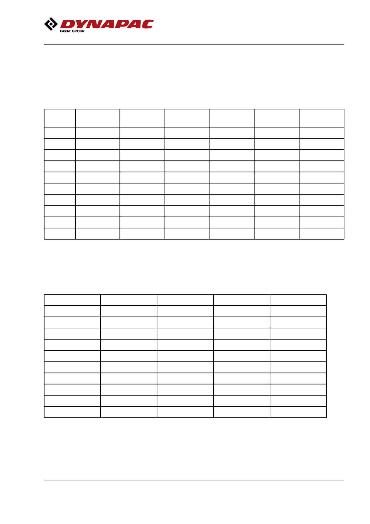
Tightening torque
Tightening torque in Nm for oiled or dry bolts tightened
with a torque wrench.
Metric coarse screw thread, bright galvanized (fzb):
PROPERTY CLASS:
M -
8.8, Oiled
8.8, Dry
10.9, Oiled
10.9, Dry
12.9, Oiled
12.9, Dry
thread
M6
8.4
9.4
12
13.4
14.6
16.3
M8
21
23
28
32
34
38
M10
40
45
56
62
68
76
M12
70
78
98
110
117
131
M14
110
123
156
174
187
208
M16
169
190
240
270
290
320
M20
330
370
470
520
560
620
M22
446
497
626
699
752
839
M24
570
640
800
900
960
1080
M30
1130
1260
1580
1770
1900
2100
Metric coarse thread, zinc-treated
(Dacromet/GEOMET):
PROPERTY CLASS:
M - thread
10.9, Oiled
10.9, Dry
12.9, Oiled
12.9, Dry
M6
12.0
15.0
14.6
18.3
M8
28
36
34
43
M10
56
70
68
86
M12
98
124
117
147
M14
156
196
187
234
M16
240
304
290
360
M20
470
585
560
698
M22
626
786
752
944
M24
800
1010
960
1215
M30
1580
1990
1900
2360
25
Technical specifications
26
Machine description
Machine description
Diesel engine
The machine is equipped with a completely
electronically controlled water-cooled four-cylinder,
turbocharged (WGT) diesel engine with direct injection
(HPCR) and intercooler.
WGT - Waste Gate Turbo
HPCR - High Pressure Common Rail fuel injection
(IIIB/T4i/T4f)
The engine is also equipped with cooled exhaust gas
recirculation (ceGR) and a diesel oxidation catalysator
(DOC) system for exhaust after-treatment.
The engine has also an electronically controlled
variable flow turbo (VFT) and closed crankcase
ventilation.
ceEGR - External Cooled EGR-electronically controlled
DOC - Diesel Oxidation Catalyst
VFT - Variable Flow turbocharger-el. controlled
(stage V)
The engine is also equipped with cooled exhaust gas
recirculation (ceEGR) and a diesel particle filter (DPF)
system for exhaust after-treatment.
The engine has also an electronically controlled
variable flow turbo (VFT) and closed crankcase
ventilation.
ceEGR - External Cooled EGR-electronically controlled
DPF - Diesel particle filter
VFT - Variable Flow turbocharger-el. controlled
Electrical system
The machine has the following control units (ECU,
Electronic Control Unit) and electronic units.
• Main ECU (for the machine)
• Diesel engine control unit (ECM)
• I/O board (Control board)
• Display
Propulsion system
The propulsion system is a hydrostatic system
A drive unit (propulsion motor + gear) drives each
drum or wheel pair.
Machines with split drum/s has a drive unit per drum
half and an anti-spin system.
All propulsion motors are connected in parallel, a
27
Machine description
hydraulic pump supplies all motors with hydraulic oil.
The speed of the machine is proportional to the angle
of the control lever (the deflection of the
forward/reverse lever regulates the speed). A speed
selector is available as option.
Brake system
The brake system comprises a service brake,
secondary brake and parking brake. The service brake
system produces retardation of the propulsion system,
i.e. hydrostatic braking.
Secondary/Parking brake
The secondary and parking brake system comprises
sprung disc brakes to each drum, drum half
respectively wheel pair.The disc brakes are
disengaged by hydraulic pressure.
Steering system
The steering system is a hydrostatic system. The
steering wheel is connected to a steering valve that
distributes the flow to the steering cylinders at the
articulated joint. A hydraulic pump supplies the
steering valve with oil.
The steering angle is proportional to the amount the
steering wheel is turned.
In some markets, the machine is also equipped with
an emergency steering system, either manually or
electro-hydraulically.
Vibration system
The vibration system is a hydrostatic system in which
a hydraulic motor drives the eccentric shaft, which
generates the drum's vibrations.
An eccentric shaft in the front-resp. rear drum
generates the the drum's vibrations.
Each eccentric shaft is driven by a hydraulic motor. A
hydraulic pump supplies each hydraulic motor with oil.
High amplitude/low frequency or low amplitude/high
frequency is controlled by the direction of rotation of
the hydraulic motor.
28
//////////////////////////////////////////