Ironhorsem General Purpose AC Motors Manual Number: IH-MT-AC_UMW Motor Series: MTR (11th Ed. – 06/29/2022) - page 10
Chapter 6: Legacy Motors
MTC EPAct Cast-Iron 3-Phase Motors Features and Specs (continued)
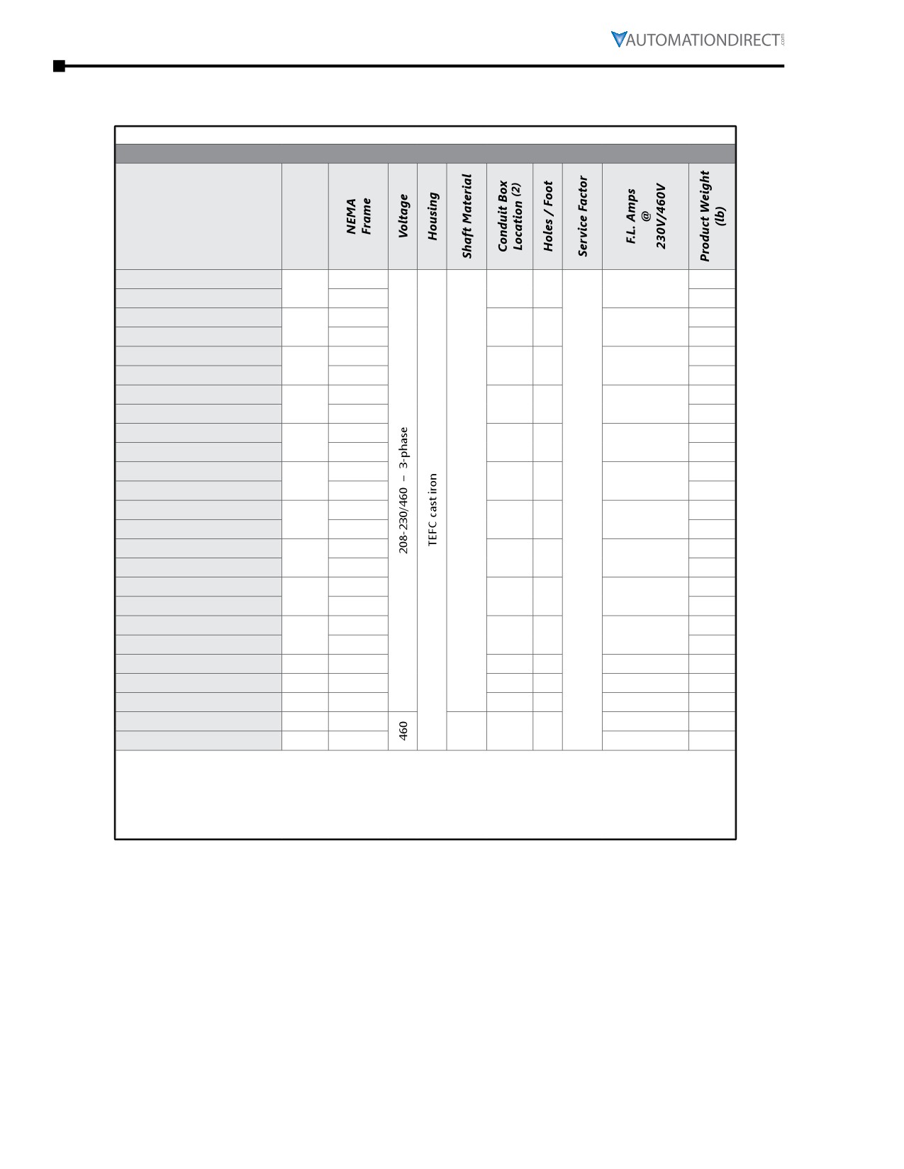
MTC Motor Specifications - Cast-Iron T-frame and TC-frame - 1800 rpm
***** Table Continued From Previous Page (for 1-7.5hp motors) *****
Motor Specifications - EPAct T & TC(1) Frame Three-Phase Motors - 1800 rpm
Part Number
HP (3)
MTC-010-3BD18
215T
179
10
F1(F2)
3
24.8 / 12.4
MTC-010-3BD18CK (1)
215TC
198
MTC-015-3BD18
254T
290
15
F1(F2)
2
35.4 / 17.7
MTC-015-3BD18CK (1)
254TC
310
MTC-020-3BD18
256T
326
20
F1(F2)
3
47.6 / 23.8
MTC-020-3BD18CK (1)
256TC
360
MTC-025-3BD18
284T
400
25
F1
2
56.4 / 28.2
MTC-025-3BD18CK (1)
284TC
440
MTC-030-3BD18
286T
451
30
F1
3
67.2 / 33.6
MTC-030-3BD18CK (1)
286TC
470
MTC-040-3BD18
324T
589
40
1045
F1
2
93.0 / 46.5
MTC-040-3BD18CK (1)
324TC
608
CS
MTC-050-3BD18 (3)
326T
1.15
640
50
F1
3
114.6 / 57.3
MTC-050-3BD18CK (1)(3)
326TC
652
MTC-060-3BD18 (3)
364T
780
60
F1
2
139.4 / 69.7
MTC-060-3BD18CK (1)(3)
364TC
780
MTC-075-3BD18 (3)
365T
870
75
F1
3
172.8 / 86.4
MTC-075-3BD18CK (1)(3)
365TC
837
MTC-100-3BD18 (3)
405T
1350
100
F1
3
230 / 115
MTC-100-3BD18CK (1)(3)
405TC
1335
MTC-125-3BD18 (3)
125
444T
F1(F2)
2
274 / 137
1500
MTC-150-3BD18 (3)
150
445T
F1(F2)
3
326 / 163
1630
MTC-200-3BD18 (3)
200
445/7T
F1(F2)
3
446 / 223
1858
MTC-250-3D18 (3)
250
449T
4140
- / 282
2508
F1
2
MTC-300-3D18 (3)
300
449T
CS
– / 334
2728
1) TC-frame motors are T-frame motors with applicable C-face accessory kits installed.
2) F1(F2) indicates F1 conduit box mounting location, field convertible to F2.
(Refer to “Chapter 5: Reference” for further information regarding F1 and F2 mounting.)
3) For warranty on motors 50 hp and above, motors must be inspected by an EASA motor repair or service
center. See AutomationDirect Terms & Conditions for details.
Page 6-34
Chapter 6: Legacy Motors
MTC EPAct Cast-Iron 3-Phase Motors Features and Specs (continued)
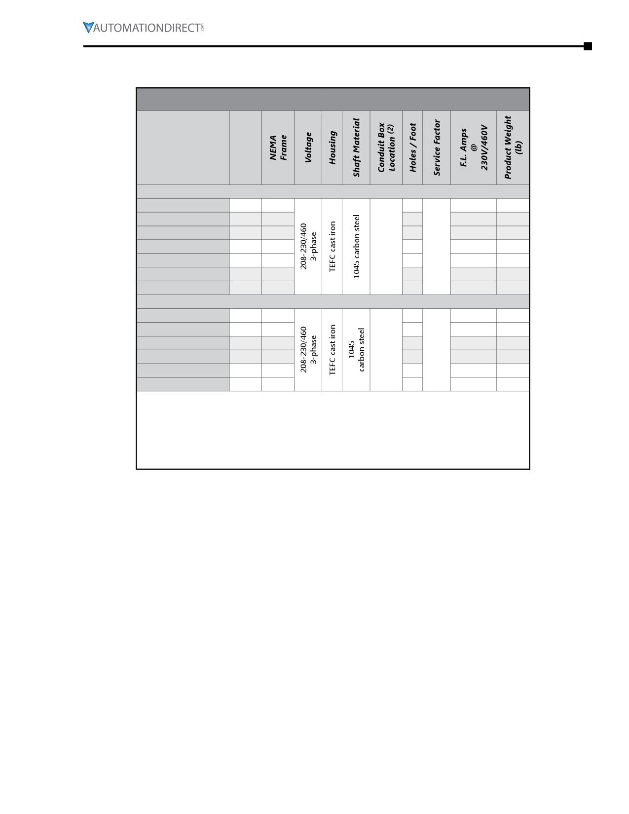
MTC Motor Specifications - Cast-Iron T-frame - 1200 & 3600 rpm
Motor Specifications - EPAct T-Frame Three-Phase Motors - 1200 & 3600 rpm
Part Number
HP (3)
1200 rpm Base Speed
MTC-001-3BD12
1
145T
4
3.2 / 1.6
62
MTC-1P5-3BD12
1-1/2
182T
2
4.8 / 2.4
106
MTC-002-3BD12
2
184T
4
6.1 / 3.1
119
MTC-003-3BD12
3
213T
F1(F2)
2
1.15
8.4 / 4.2
171
MTC-005-3BD12
5
215T
4
13.6 / 6.8
189
MTC-7P5-3BD12
7-1/2
254T
2
21.2 / 10.6
272
MTC-010-3BD12
10
256T
4
28.0 / 14.0
307
3600 rpm Base Speed
MTC-1P5-3BD36
1-1/2
143T
2
3.8 / 1.9
62
MTC-002-3BD36
2
145T
4
5.0 / 2.5
66
MTC-003-3BD36
3
182T
2
7.2 / 3.6
107
F1(F2)
1.15
MTC-005-3BD36
5
184T
4
11.3 / 5.7
112
MTC-7P5-3BD36
7-1/2
213T
2
16.8 / 8.4
165
MTC-010-3BD36
10
215T
4
22.4 / 11.2
185
2) F1(F2) indicates F1 conduit box mounting location, field convertible to F2.
(Refer to “Chapter 5: Reference” for further information regarding F1 and F2
mounting.)
3) For warranty on motors 50 hp and above, motors must be inspected by an EASA
motor repair or service center. See AutomationDirect Terms & Conditions for
details.
IronHorse® General Purpose
AC Motors User Manual - 11th Ed. - 06/29/2022
Page 6-35
Chapter 6: Legacy Motors
MTC EPAct Cast-Iron 3-Phase Motors Features and Specs (continued)
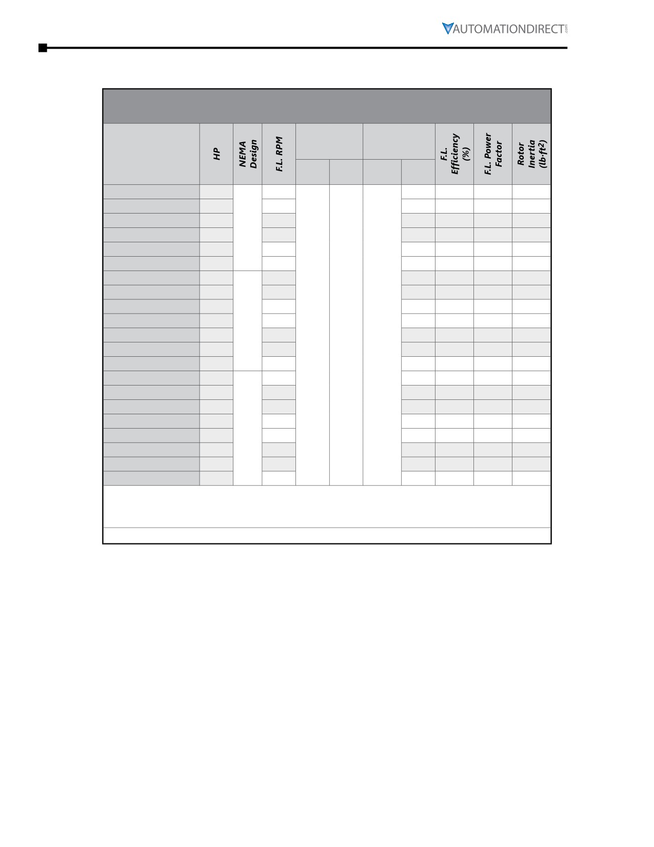
MTC Motor Performance Data - Cast-Iron T-Frame and TC-frame - 1800 rpm
Performance Data - EPAct T & TC(1) Frame Three-Phase Motors - 1800 rpm
(460 Volt except as indicated)
Minimum
Maximum
Speed
Speed
Part Number
(rpm)
(rpm)
CT
VT
CHP(2)
Safe
(2:1)
(5:1)
MTC-001-3BD18(CK)
1
1760
5400
82.5
0.71
0.068
MTC-1P5-3BD18(CK)
1-1/2
1755
5400
84.0
0.74
0.083
MTC-002-3BD18(CK)
2
1750
5400
84.0
0.77
0.09
B
MTC-003-3BD18(CK)
3
1750
5400
87.5
0.81
0.22
MTC-005-3BD18(CK)
5
1750
5400
87.5
0.84
0.285
MTC-7P5-3BD18(CK)
7-1/2
1760
5400
89.5
0.81
0.602
MTC-010-3BD18(CK)
10
1760
4200
89.5
0.83
0.742
MTC-015-3BD18(CK)
15
1770
4200
91.0
0.83
1.71
MTC-020-3BD18(CK)
20
1770
4200
91.0
0.84
2.18
MTC-025-3BD18(CK)
25
A
1775
4200
92.4
0.87
3.3
MTC-030-3BD18(CK)
30
1775
900
360
2700
4200
92.4
0.86
3.76
MTC-040-3BD18(CK)
40
1775
3600
93.0
0.86
5.84
MTC-050-3BD18(CK)
50
1775
3600
93.0
0.86
6.34
MTC-060-3BD18(CK)
60
1785
3600
93.6
0.85
11.4
MTC-075-3BD18(CK)
75
1785
3600
94.1
0.84
12.7
MTC-100-3BD18(CK)
100
1785
2800
94.5
0.87
28.5
MTC-125-3BD18
125
1785
2800
94.5
0.86
38.9
B
MTC-150-3BD18
150
1785
2800
95.0
0.87
47.2
MTC-200-3BD18
200
1785
2800
95.0
0.87
62.3
MTC-250-3D18
250
1790
2800
95.9
0.87
86.0
MTC-300-3D18
300
1790
2800
95.7
0.88
105.0
1) TC-frame motors (MTC-xxx-xxxxCK) are T-frame motors with applicable C-face accessory
kits installed.
2) Maximum Constant HP RPM is for direct-coupled loads.
*** TABLE CONTINUED NEXT PAGE ***
Page 6-36
Chapter 6: Legacy Motors
MTC EPAct Cast-Iron 3-Phase Motors Features and Specs (continued)
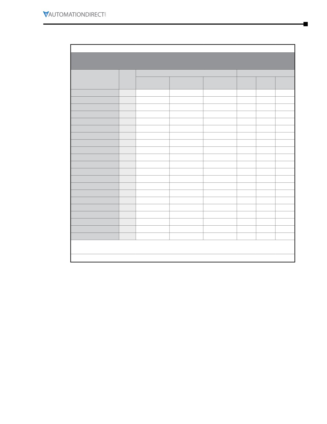
MTC Motor Performance Data - Cast-Iron T-Frame and TC-frame - 1800 rpm
***** Table Continued From Previous Page
*****
Performance Data - EPAct T & TC(1) Frame 3-Phase Motors - 1800 rpm
(460 Volt except as indicated)
Current @ 230V/460V (Amps)
Torque (lb·ft)
Part
HP
No
Full
Locked
Full
Locked
Break
Number
Load
Load
Rotor
Load
Rotor
-down
MTC-001-3BD18(CK)
1
1.9 / 0.95
3.0 / 1.5
30.0 / 15.0
3.00
7.50
10.50
MTC-1P5-3BD18(CK)
1-1/2
2.44 / 1.22
4.2 / 2.1
40.0 / 20.0
4.41
10.58
14.11
MTC-002-3BD18(CK)
2
2.76 / 1.38
5.4 / 2.7
50.0 / 25.0
6.05
13.92
17.55
MTC-003-3BD18(CK)
3
3.74 / 1.87
7.72 / 3.86
64.0 / 32.0
9.07
25.40
29.93
MTC-005-3BD18(CK)
5
5.1 / 2.55
11.8 / 5.9
92.0 / 46.0
15.1
40.8
46.8
MTC-7P5-3BD18(CK)
7-1/2
8.98 / 4.49
18.6 / 9.3
127 / 63.5
22.0
44.0
72.6
MTC-010-3BD18(CK)
10
13.0 / 6.5
24.8 / 12.4
200 / 100
29.8
59.6
92.4
MTC-015-3BD18(CK)
15
15.6 / 7.8
35.4 / 17.7
280 / 140
44.5
89.0
124.6
MTC-020-3BD18(CK)
20
19.0 / 9.5
47.6 / 23.8
400 / 200
59.7
119.4
155.2
MTC-025-3BD18(CK)
25
24.0 / 12.0
56.4 / 28.2
440 / 220
73.9
152.2
206.9
MTC-030-3BD18(CK)
30
27.0 / 13.5
67.2 / 33.6
520 / 260
88.7
177.4
257.2
MTC-040-3BD18(CK)
40
35.0 / 17.5
93.0 / 46.5
720 / 360
118
248
355
MTC-050-3BD18(CK)
50
38.6 / 19.3
114.6 / 57.3
880 / 440
148
311
444
MTC-060-3BD18(CK)
60
48.0 / 24.0
139.4 / 69.7
870 / 435
179
322
483
MTC-075-3BD18(CK)
75
59.2 / 29.6
172.8 / 86.4
1086 / 543
221
398
530
MTC-100-3BD18(CK)
100
72.0 / 36.0
230 / 115
1450 / 725
296
592
858
MTC-125-3BD18
125
82.0 / 41.0
274 / 137
1815 / 908
355
604
888
MTC-150-3BD18
150
97.6 / 48.8
326 / 163
2170 / 1085
433
779
1083
MTC-200-3BD18
200
140 / 70.0
446 / 223
2900 / 1450
590
1180
1652
MTC-250-3D18
250
- / 85.6
- / 282
- / 2017
728
1660
2402
MTC-300-3D18
300
- / 96.6
- / 334
- / 2351
864
1953
2817
1) TC-frame motors (MTC-xxx-xxxxCK) are T-frame motors with applicable C-face accessory
kits installed.
*** TABLE CONTINUED NEXT PAGE ***
IronHorse® General Purpose
AC Motors User Manual - 11th Ed. - 06/29/2022
Page 6-37
Chapter 6: Legacy Motors
MTC EPAct Cast-Iron 3-Phase Motors Features and Specs (continued)
MTC Motor Performance Data - Cast-Iron T-Frame and TC-frame - 1800 rpm
*** TABLE CONTINUED FROM PREVIOUS PAGE ***
Performance Data
EPAct T & TC(1) Frame Three-Phase Motors
1800 rpm - (460 Volt except as indicated)
Max Time @
Temperature
Part
Slip
HP
Locked Rotor
Rise
Number
(%)
Current (hot)
@ Full Load
MTC-001-3BD18(CK)
1
2.22
MTC-1P5-3BD18(CK)
1-1/2
2.50
MTC-002-3BD18(CK)
2
2.78
20 seconds
MTC-003-3BD18(CK)
3
2.78
MTC-005-3BD18(CK)
5
2.78
MTC-7P5-3BD18(CK)
7-1/2
2.22
MTC-010-3BD18(CK)
10
2.20
13 seconds
MTC-015-3BD18(CK)
15
1.67
20 seconds
MTC-020-3BD18(CK)
20
1.67
MTC-025-3BD18(CK)
25
1.38
16 seconds
80° C (176°F)
MTC-030-3BD18(CK)
30
1.38
MTC-040-3BD18(CK)
40
1.39
MTC-050-3BD18(CK)
50
1.39
20 seconds
MTC-060-3BD18(CK)
60
0.83
MTC-075-3BD18(CK)
75
0.83
MTC-100-3BD18(CK)
100
0.83
MTC-125-3BD18
125
0.83
15 seconds
MTC-150-3BD18
150
0.83
MTC-200-3BD18
200
0.83
MTC-250-3D18
250
0.54
20 seconds
85° C (185°F)
MTC-300-3D18
300
0.53
1) TC-frame motors (MTC-xxx-xxxxCK) are T-frame motors with
applicable C-face accessory kits installed.
Page 6-38
Chapter 6: Legacy Motors
MTC EPAct Cast-Iron 3-Phase Motors Features and Specs (continued)
MTC Motor Performance Data - Cast-Iron T-Frame - 1200 rpm
Performance Data - EPAct T-Frame Three-Phase Motors - 1200 rpm
(460 Volt except as indicated)
Maximum
Minimum Speed (rpm)
Speed (rpm)
F.L.
Part Number
HP
Constant
Variable
RPM
Torque
Torque
CHP(2)
Safe
(2:1)
(5:1)
MTC-001-3BD12
1
1150
MTC-1P5-3BD12
1-1/2
1170
MTC-002-3BD12
2
B
MTC-003-3BD12
3
600
240
1800
3600
MTC-005-3BD12
5
1180
MTC-7P5-3BD12
7-1/2
MTC-010-3BD12
10
A
Current @ 230V/460V (Amps)
Torque (lb·ft)
Part Number
HP
Locked
Full
Locked
Break-
No Load
Full Load
Rotor
Load
Rotor
down
MTC-001-3BD12
1
3.2 / 1.6
3.2 / 1.6
25.0 / 12.5
4.59
11.48
14.69
MTC-1P5-3BD12
1-1/2
3.5 / 1.8
4.8 / 2.4
40.0 / 20.0
6.60
18.5
24.4
MTC-002-3BD12
2
4.0 / 2.0
6.1 / 3.1
50.0 / 25.0
9.02
24.4
30.7
MTC-003-3BD12
3
4.7 / 2.4
8.4 / 4.2
64.0 / 32.0
13.4
22.8
37.5
MTC-005-3BD12
5
7.3 / 3.7
13.6 / 6.8
92.0 / 46.0
22.2
37.7
53.3
MTC-7P5-3BD12
7-1/2
12.6 / 6.3
21.2 / 10.6
127 / 63.5
32.9
75.7
98.7
MTC-010-3BD12
10
7.6 / 3.8
28.0 / 14.0
168 / 84.0
44.8
98.6
139
Temperature
Max Time
F.L.
F.L.
Rotor
Slip
Part Number
HP
Rise
Locked
Efficiency
Power
Inertia
(%)
@ Full Load
Rotor (Hot)
(%)
Factor
(lb·ft2)
MTC-001-3BD12
1
81.1
0.72
0.009
3.3
MTC-1P5-3BD12
1-1/2
85.5
0.65
0.068
2.5
MTC-002-3BD12
2
86.5
0.70
0.100
2.5
80°C
20
MTC-003-3BD12
3
87.5
0.72
0.207
1.7
(176°F)
seconds
MTC-005-3BD12
5
87.5
0.72
0.258
1.7
MTC-7P5-3BD12
7-1/2
89.5
0.71
0.480
1.7
MTC-010-3BD12
10
89.5
0.74
2.487
1.7
2) Maximum Constant HP RPM is for direct-coupled loads
IronHorse® General Purpose
AC Motors User Manual - 11th Ed. - 06/29/2022
Page 6-39
Chapter 6: Legacy Motors
MTC EPAct Cast-Iron 3-Phase Motors Features and Specs (continued)
MTC Motor Performance Data - Cast-Iron T-Frame - 3600 rpm
Performance Data - EPAct T-Frame Three-Phase Motors - 3600 rpm
(460 Volt except as indicated)
Maximum
Minimum Speed (rpm)
Speed (rpm)
F.L.
Part Number
HP
Constant
Variable
RPM
Torque
Torque
CHP(2)
Safe
(2:1)
(5:1)
MTC-1P5-3BD36
1-1/2
3480
MTC-002-3BD36
2
MTC-003-3BD36
3
3520
B
1800
720
5400
5400
MTC-005-3BD36
5
3510
MTC-7P5-3BD36
7-1/2
3520
MTC-010-3BD36
10
3530
Current @ 230V/460V (Amps)
Torque (lb·ft)
Part Number
HP
Locked
Full
Locked
Break-
No Load
Full Load
Rotor
Load
Rotor
down
MTC-1P5-3BD36
1-1/2
1.4 / 0.7
3.8 / 1.9
40.0 / 20.0
2.23
4.01
5.58
MTC-002-3BD36
2
1.5 / 0.8
5.0 / 2.5
50.0 / 25.0
3.03
6.06
8.18
MTC-003-3BD36
3
2.8 / 1.4
7.2 / 3.6
64.0 / 32.0
4.50
10.4
16.2
MTC-005-3BD36
5
4.0 / 2.0
11.3 / 5.7
92.0 / 46.0
7.46
15.7
26.5
MTC-7P5-3BD36
7-1/2
5.0 / 2.5
16.8 / 8.4
127 / 63.5
11.0
22.0
36.3
MTC-010-3BD36
10
5.7 / 2.8
22.4 / 11.2
162 / 81.0
15.0
33.0
49.5
Tempera-
Max Time
F.L.
F.L.
Rotor
ture Rise
Slip
Part Number
HP
Locked
Efficiency
Power
Inertia
@
(%)
Rotor (Hot)
(%)
Factor
(lb·ft2)
Full Load
MTC-1P5-3BD36
1-1/2
82.5
0.86
0.009
3.3
MTC-002-3BD36
2
84.0
0.87
0.010
3.3
MTC-003-3BD36
3
80°C
85.5
0.86
0.034
2.2
20 seconds
MTC-005-3BD36
5
(176°F)
87.5
0.88
0.040
2.5
MTC-7P5-3BD36
7-1/2
88.5
0.89
0.258
2.2
MTC-010-3BD36
10
89.5
0.89
0.109
1.9
2) Maximum Constant HP RPM is for direct-coupled loads
Page 6-40
Chapter 6: Legacy Motors
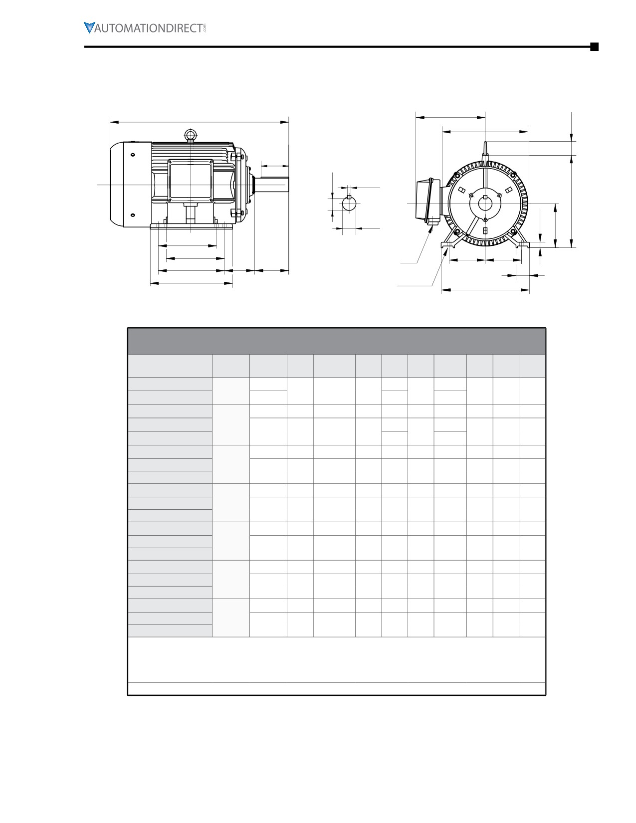
MTC Motor Dimensions
(Dimensions = inches)
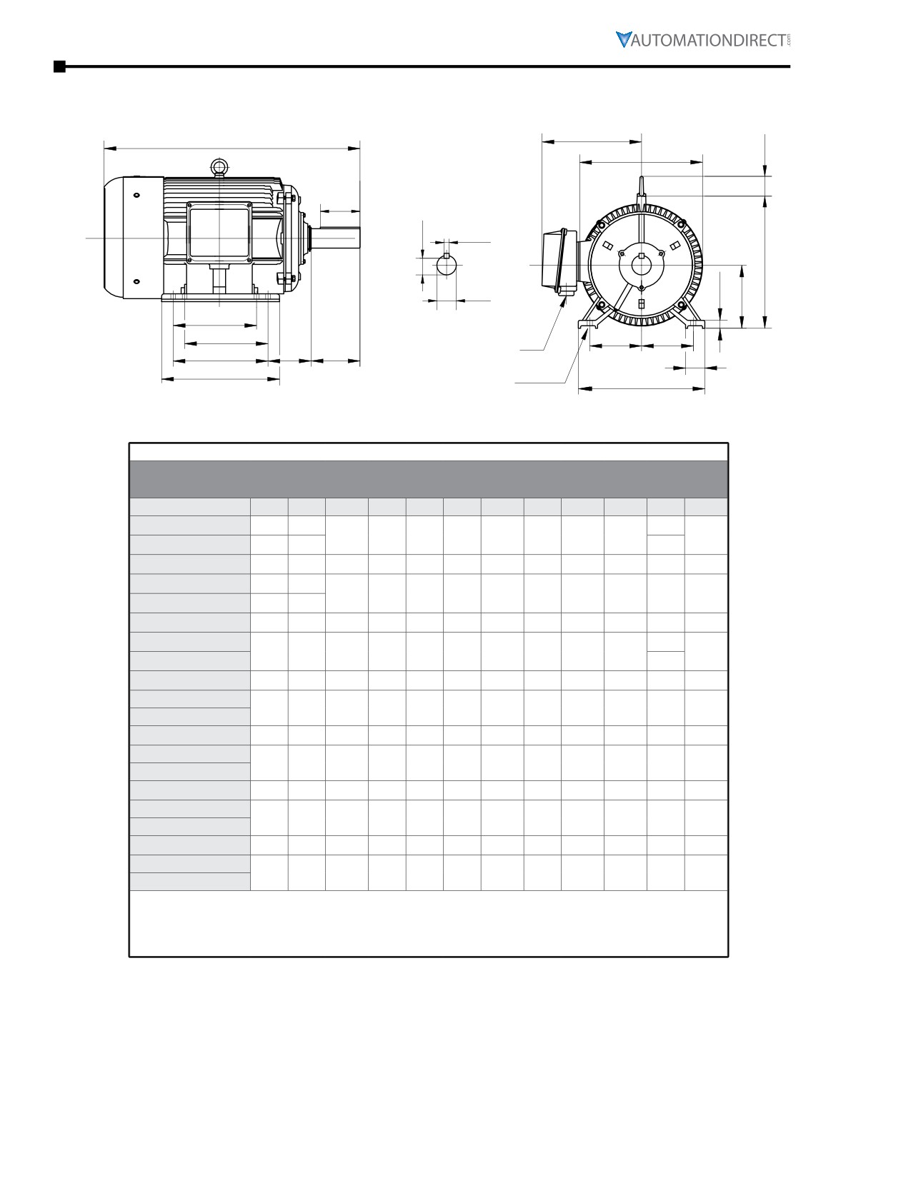
MTC EPAct T-Frame Three-Phase Motor Dimensions
AB
C
T
P
ES
R
S
O
U
G
D
F1*
F1*
E
E
AA**
F2*
BA
N-W
J
B
H (hole)
A
* Various frame sizes have 2 or 4
** F1 mounting shown.
mounting holes per mounting foot
** Some frame sizes are F1/F2 convertible.
(one mounting foot per side).
Dimensions [inches, except as noted]
EPAct Three-phase T-Frame Motors - 1200, 1800, 3600 rpm
NEMA
Part Number
HP
A
AA**
AB
B
BA
C
D
E
ES
Frame
MTC-001-3BD12
145T
6
13.58
1
7
3/4”npt
6.89
2.25
3.5
2.75
1.41
MTC-001-3BD18
143T
5
12.57
MTC-1P5-3BD12
182T
9
1” NPT
7.45
6.5
2.75
15.11
4.5
3.75
1.78
MTC-1P5-3BD18
1-1/2
6
13.58
145T
7
3/4”npt
6.89
2.25
3.5
2.75
1.41
MTC-1P5-3BD36
5
12.57
MTC-002-3BD12
184T
9
1” NPT
7.45
7.5
2.75
16.11
4.5
3.75
1.78
MTC-002-3BD18
2
145T
7
3/4”npt
6.89
6
2.25
13.58
3.5
2.75
1.41
MTC-002-3BD36
MTC-003-3BD12
213T
10.5
1” NPT
8.63
7.5
3.5
18.89
5.25
4.25
2.41
MTC-003-3BD18
3
182T
9
1” NPT
7.45
6.5
2.75
15.11
4.5
3.75
1.78
MTC-003-3BD36
MTC-005-3BD12
215T
10.5
1” NPT
8.63
9
3.5
20.49
5.25
4.25
2.41
MTC-005-3BD18
5
184T
9
1” NPT
7.45
7.5
2.75
16.11
4.5
3.75
1.78
MTC-005-3BD36
MTC-7P5-3BD12
254T
12.5
1.5” NPT
11.2
10.8
4.25
23.29
6.25
5
2.91
MTC-7P5-3BD18
7-1/2
213T
10.5
1” NPT
8.63
7.5
3.5
18.89
5.25
4.25
2.41
MTC-7P5-3BD36
MTC-010-3BD12
256T
12.5
1.5” NPT
11.2
12.5
4.25
25.06
6.25
5
2.91
MTC-010-3BD18
10
215T
10.5
1” NPT
8.63
9
3.5
20.49
5.25
4.25
2.41
MTC-010-3BD36
* Various frame sizes have 2 or 4 mounting holes per mounting foot.
** AA dimension is conduit fitting size.
F1 mounting shown; some frame sizes are F1/F2 convertible; refer to T-frame “Motor Specifications”
table.
(F2 mounting = conduit entrance on right side facing shaft.)
**** TABLE CONTINUED NEXT PAGE (for dimensions F1-U) ****
IronHorse® General Purpose
AC Motors User Manual - 11th Ed. - 06/29/2022
Page 6-41
Chapter 6: Legacy Motors
MTC Motor Dimensions (continued) - (Dimensions = inches)
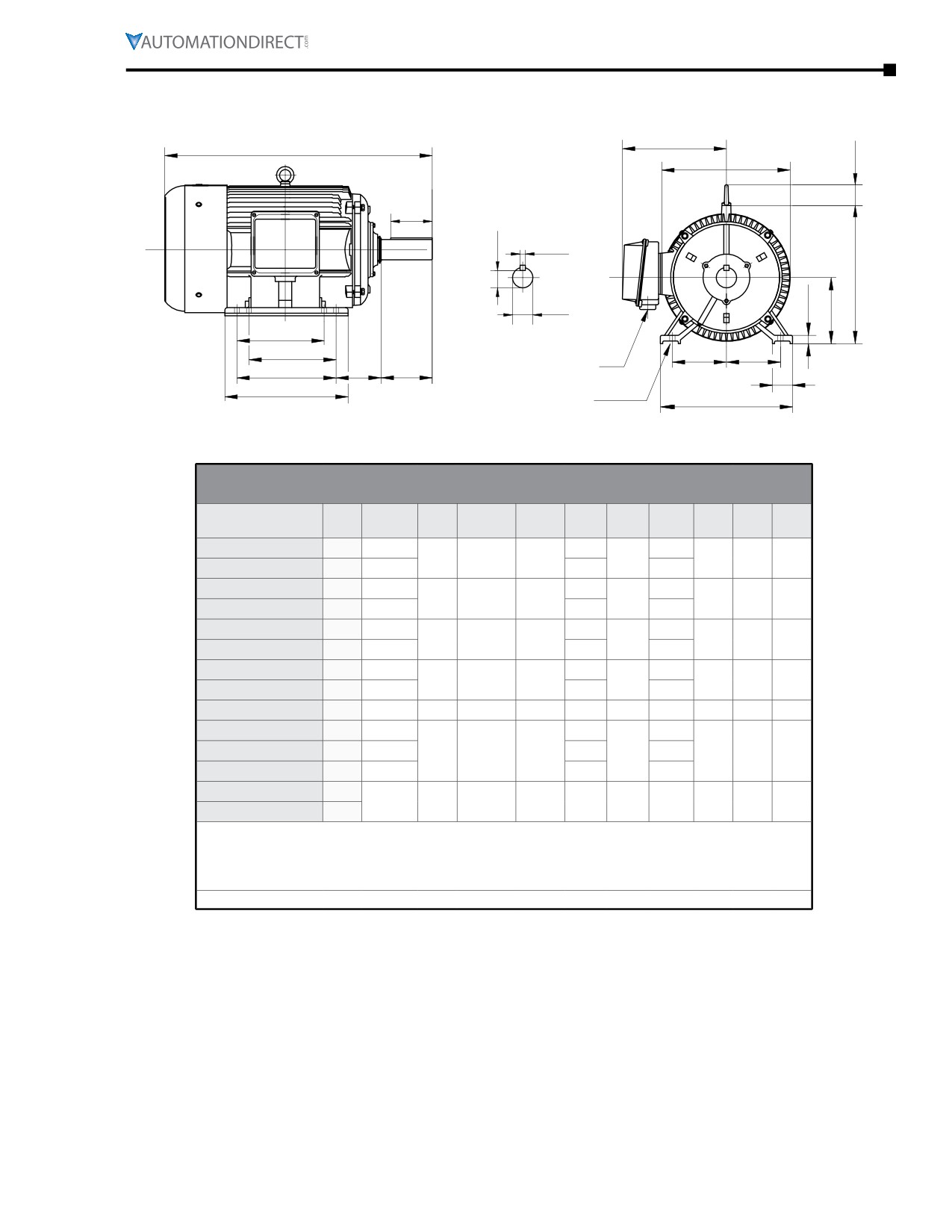
MTC EPAct T-Frame Three-Phase Motor Dimensions (continued)
AB
C
T
P
ES
R
S
O
U
G
D
F1*
F1*
E
E
AA**
F2*
BA
N-W
J
B
H (hole)
A
* Various frame sizes have 2 or 4
** F1 mounting shown.
mounting holes per mounting foot
** Some frame sizes are F1/F2 convertible.
(one mounting foot per side).
**** Table Continued Previous Page (for dimensions A-ES) ****
Dimensions [inches, except as noted]
EPAct Three-phase T-Frame Motors - 1200, 1800, 3600 rpm
Part Number
F1*
F2*
G
H
J
N-W
O
P
R
S
T
U
MTC-001-3BD12
4
5
0.88
0.512
0.34
1.45
2.25
7.08
7.16
0.771
0.188
0.875
MTC-001-3BD18
n/a
4
n/a
MTC-1P5-3BD12
n/a
4.5
0.59
0.41
1.97
2.75
8.97
8.82
0.986
0.25
1.42
1.125
MTC-1P5-3BD18
4
5
0.512
0.34
1.45
2.25
7.08
7.16
0.771
0.188
n/a
0.875
MTC-1P5-3BD36
n/a
4
MTC-002-3BD12
4.5
5.5
0.59
0.41
1.97
2.75
8.97
8.82
0.986
0.25
1.42
1.125
MTC-002-3BD18
n/a
4
5
0.512
0.34
1.45
2.25
7.08
7.16
0.771
0.188
0.875
MTC-002-3BD36
0.88
MTC-003-3BD12
n/a
5.5
0.709
0.41
2.36
3.38
10.53
10.4
1.201
0.312
1.73
1.375
MTC-003-3BD18
n/a
4.5
0.59
0.41
1.97
2.75
8.97
8.82
0.986
0.25
1.42
1.125
MTC-003-3BD36
MTC-005-3BD12
5.5
7
0.709
0.41
2.36
3.38
10.53
10.4
1.201
0.312
1.73
1.375
MTC-005-3BD18
4.5
5.5
0.59
0.41
1.97
2.75
8.97
8.82
0.986
0.25
1.42
1.125
MTC-005-3BD36
MTC-7P5-3BD12
n/a
8.25
0.787
0.53
2.76
4
12.89
12.6
1.416
0.375
2.05
1.625
MTC-7P5-3BD18
n/a
5.5
0.709
0.41
2.36
3.38
10.53
10.4
1.201
0.312
1.73
1.375
MTC-7P5-3BD36
MTC-010-3BD12
8.25
10
0.787
0.53
2.76
4
12.89
12.6
1.416
0.375
2.05
1.625
MTC-010-3BD18
5.5
7
0.709
0.41
2.36
3.38
10.53
10.4
1.201
0.312
1.73
1.375
MTC-010-3BD36
* Various frame sizes have 2 or 4 mounting holes per mounting foot.
** AA dimension is conduit fitting size.
F1 mounting shown; some frame sizes are F1/F2 convertible; refer to T-frame “Motor Specifications”
table.
(F2 mounting = conduit entrance on right side facing shaft.)
Page 6-42
Chapter 6: Legacy Motors
MTC Motor Dimensions (continued) - (Dimensions = inches)
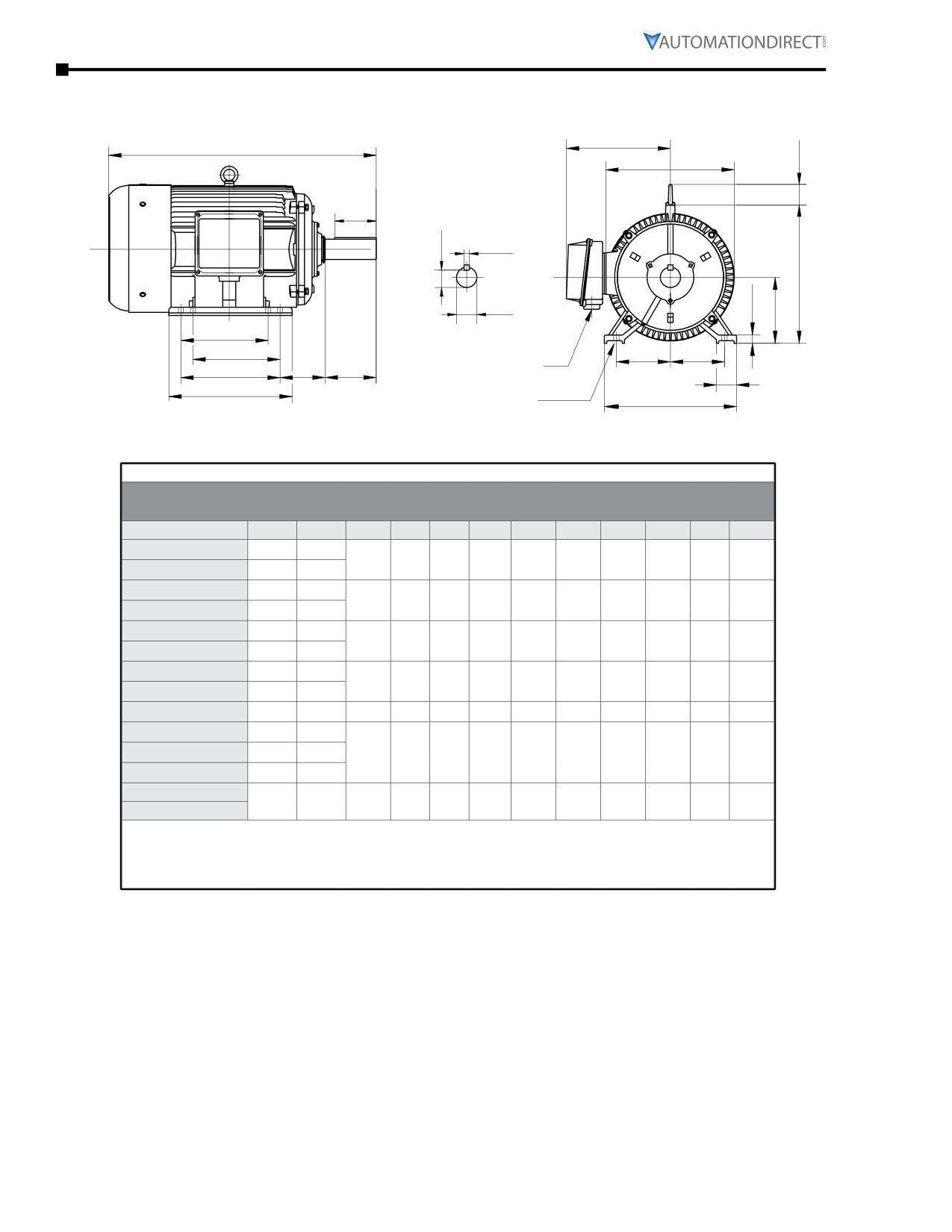
MTC EPAct T-Frame Three-Phase Motor Dimensions (continued)
AB
C
T
P
ES
R
S
O
G
U
D
F1*
F1*
E
E
AA**
F2*
BA
N-W
J
B
H (hole)
A
* Various frame sizes have 2 or 4
** F1 mounting shown.
mounting holes per mounting foot
** Some frame sizes are F1/F2 convertible.
(one mounting foot per side).
Dimensions [inches, except as noted]
EPAct Three-phase T-Frame Motors - 1800 rpm
NEMA
Part Number
HP
A
AA**
AB
B
BA
C
D
E
ES
Frame
MTC-015-3BD18
15
254T
10.8
23.29
12.5
1.5” NPT
11.2
4.25
6.25
5
2.91
MTC-020-3BD18
20
256T
12.5
25.06
MTC-025-3BD18
25
284T
12.5
26.64
14
1.5” NPT
12
4.75
7
5.5
3.28
MTC-030-3BD18
30
286T
14
28.18
MTC-040-3BD18
40
324T
14
29.95
16
2” NPT
13.4
5.25
8
6.25
3.91
MTC-050-3BD18
50
326T
15.5
31.24
MTC-060-3BD18
60
364T
15.2
32.68
18
3” NPT
15.7
5.88
9
7
4.28
MTC-075-3BD18
75
365T
16.2
34.11
MTC-100-3BD18
100
405T
20
3” NPT
18.31
17.8
6.62
38.35
10
8
5.65
MTC-125-3BD18
125
444T
18.5
42.52
MTC-150-3BD18
150
445T
22
2x3”NPT
19.41
20.5
7.5
44.5
11
9
6.91
MTC-200-3BD18
200
445/7T
24
48.03
MTC-250-3D18
250
449T
22
2x3”NPT
19.07
31
7.5
55.51
11
9
7.01
MTC-300-3D18
300
* Various frame sizes have 2 or 4 mounting holes per mounting foot.
** AA dimension is conduit fitting size.
F1 mounting shown; some frame sizes are F1/F2 convertible; refer to T-frame “Motor
Specifications” table.
(F2 mounting = conduit entrance on right side facing shaft.)
**** TABLE CONTINUED NEXT PAGE (for dimensions F1-U) ****
IronHorse® General Purpose
AC Motors User Manual - 11th Ed. - 06/29/2022
Page 6-43
Chapter 6: Legacy Motors
MTC Motor Dimensions (continued) - (Dimensions = inches)
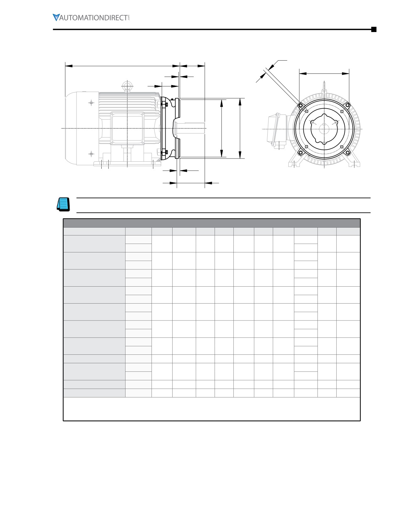
MTC EPAct T-Frame Three-Phase Motor Dimensions (continued)
AB
C
T
P
ES
R
S
O
U
G
D
F1*
F1*
E
E
AA**
F2*
BA
N-W
J
B
H (hole)
A
* Various frame sizes have 2 or 4
** F1 mounting shown.
mounting holes per mounting foot
** Some frame sizes are F1/F2 convertible.
(one mounting foot per side).
**** Table Continued Previous Page (for dimensions A-ES) ****
Dimensions [inches, except as noted]
EPAct Three-phase T-Frame Motors - 1800 rpm
Part Number
F1*
F2*
G
H
J
N-W
O
P
R
S
T
U
MTC-015-3BD18
n/a
8.25
0.787
0.53
2.76
4
12.89
12.6
1.416
0.375
2.05
1.625
MTC-020-3BD18
8.25
10
MTC-025-3BD18
n/a
9.5
0.866
0.53
2.76
4.62
14.28
14.17
1.591
0.5
2.05
1.875
MTC-030-3BD18
9.5
11
MTC-040-3BD18
n/a
10.5
0.984
0.66
2.76
5.25
15.91
15.75
1.845
0.5
2.44
2.125
MTC-050-3BD18
10.5
12
MTC-060-3BD18
n/a
11.25
1.102
0.66
2.95
5.88
18.13
17.7
2.021
0.625
2.44
2.375
MTC-075-3BD18
11.25
12.25
MTC-100-3BD18
12.25
13.75
1.18
0.81
3.15
7.25
21.02
21.42
2.45
0.75
2.83
2.875
MTC-125-3BD18
n/a
14.5
MTC-150-3BD18
14.5
16.5
1.38
0.81
3.35
8.5
22.97
23.43
2.88
0.875
3.46
3.375
MTC-200-3BD18
16.5
20
MTC-250-3D18
n/a
25
1.575
0.81
3.35
8.5
23
24
2.88
0.875
4.25
3.375
MTC-300-3D18
* Various frame sizes have 2 or 4 mounting holes per mounting foot.
** AA dimension is conduit fitting size.
F1 mounting shown; some frame sizes are F1/F2 convertible; refer to T-frame “Motor Specifications”
table.
(F2 mounting = conduit entrance on right side facing shaft.)
Page 6-44
Chapter 6: Legacy Motors
MTC Motor Dimensions (continued) - (Dimensions = inches)
MTC EPAct TC-Frame Three-Phase Motor & C-Flange Dimensions
BF
CB
AH
AJ
BB
CC
AK
BD
BC
N-W
TC-frame motors are T-frame EPAct motors with C-flange accessory kits installed. For more information
about the C-flange accessory kits, refer to Chapter 4: Accessories.
Dimensions (inches) - EPAct T-Frame Motor C-Flange Kits
Part Number
Frame
AH(2)
AJ
AK
BB
BC(2)
BD
BF
CB(2)
CC
N-W(2)
143T
10.51
MTA-CFACE-140TC(1)
1.96
5.875
(1)
4.5
(1)
0.16
0.12
6.5
3/8-16
1.43
2.25
145T
11.62
182T
12.49
MTA-CFACE-180TC
2.62
7.25
8.5
0.25
0.12
9
1/2-13
1.17
2.75
184T
13.49
213T
15.77
MTA-CFACE-210TC
3.12
7.25
8.5
0.25
0.25
9
1/2-13
1.45
3.38
215T
17.37
254T
19.54
MTA-CFACE-250TC
3.75
7.25
8.5
0.25
0.25
10
1/2-13
2.89
4
256T
21.31
284T
22.26
MTA-CFACE-280TC
4.38
9
10.5
0.25
0.25
11.25
1/2-13
3.26
4.62
286T
23.80
324T
24.95
MTA-CFACE-320TC
5
11
12.5
0.25
0.25
14
5/8-11
3.67
5.25
326T
26.24
364T
27.06
MTA-CFACE-360TC
5.62
11
12.5
0.25
0.25
14
5/8-11
4.06
5.88
365T
28.49
MTA-CFACE-400TC
405T
7
11
12.5
0.25
0.25
15.5
5/8-11
31.35
4.33
7.25
444T
34.27
MTA-CFACE-444TC
8.25
14
16
0.25
0.25
18
5/8-11
4.11
8.5
445T
36.25
MTA-CFACE-447TC
445/7T
8.25
14
16
0.25
0.25
18
5/8-11
39.78
4.11
8.5
MTA-CFACE-449TC
449T
8.248
14
16
0.26
0.26
17.72
5/8-11
47.26
4.35
8.5
1) Mounting bolt holes for MTA-CFACE-140TC are located outside of the highest C-face flange surface
(dimension AJ > AK).
2) Motor dependent dimensions apply only to IronHorse MTC-xxx-xxxxx(CK) motors.
IronHorse® General PurposeAC Motors User Manual - 11th Ed. - 06/29/2022
Page 6-45
Chapter 6: Legacy Motors
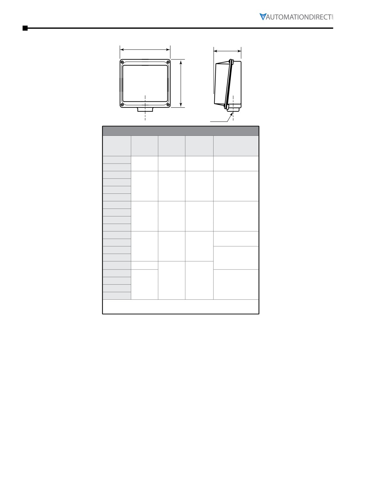
MTC Junction Box Dimensions
XD
HH
XC
AA
Junction Box Dimensions (in)
AA
Frame
XD
XC
HH
(Conduit Hole)
Size *
(Width)
(Height)
(Depth)
(NPT)
143T
4.1
4.5
2.3
3/4
145T
182T
184T
4.6
5.0
2.6
1
213T
215T
254T
256T
6.3
7.2
3.3
1-1/2
284T
286T
324T
2
326T
9
10.6
5.3
364T
365T
3
405T
9.8
444T
445T
11.7
7.1
11.3
3 (2 openings)
445/7T
449T
* TC-frame motors have the same junction boxes as the
comparable T-frame motors.
Page 6-46
Chapter 6: Legacy Motors
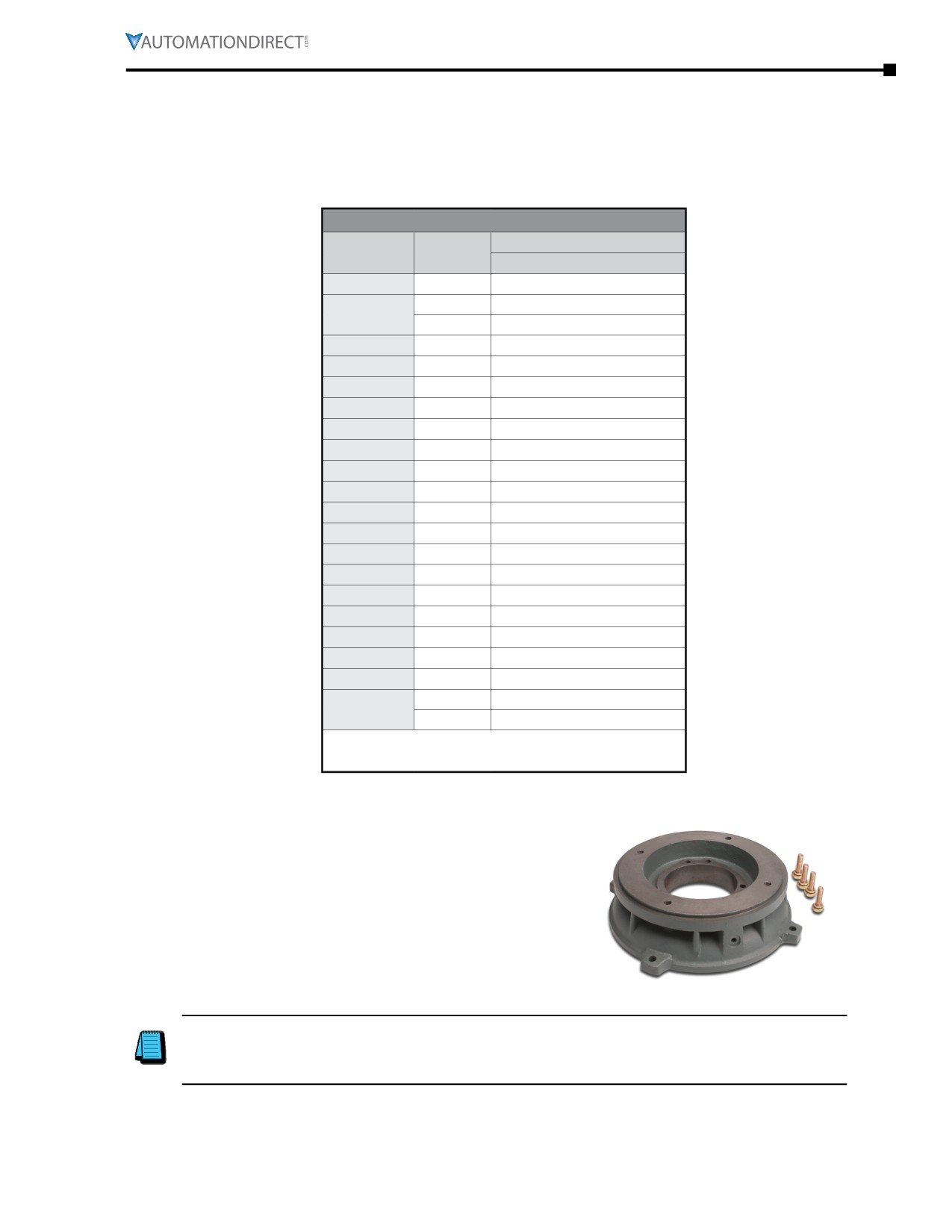
MTC Motors Decibel Levels
The decibel (sound) level of an IronHorse® motor should be measured after initial startup, after 30 days,
and after six months of use. Decibel levels should remain fairly consistent and can be an indication
of misalignment and premature bearing wear. If the measured decibel level for your IronHorse model
exceeds the value listed below by more than 10%, contact AutomationDirect or a local motor service
technician found at www.easa.com.
MTC Average T-Frame Decibel Levels
Noise Level: Lw dB(A) @ 1m
Frame Size *
HP
MTC
143T
1
64.0
1-1/2
68.0
145T
2
68.8
182T
2
-
182T
3
74.0
184T
5
73.0
213T
7-1/2
78.4
215T
10
74.3
254T
15
74.6
256T
20
74.0
284T
25
75.0
286T
30
76.1
324T
40
76.4
326T
50
77.0
364T
60
77.1
365T
75
78.0
405T
100
78.1
444T
125
78.3
445T
150
79.4
445/7T
200
79.4
250
81.0
449T
300
81.4
* TC-frame motors have the same sound ratings as
the comparable T-frame motors.
C-Flange Kits for MTC EPAct Three-Phase Motors
C-Flange Kits
Any IronHorse MTC EPAct T-frame cast-iron motor from
1-300hp can be converted to C-face mounting by using a
cast iron C-flange kit. These kits are field installable and
include the C-faces and mounting bolts.
C-Flange Dimensions
C-flange dimensions are shown in Chapter 2 (Mounting &
Initial Startup) along with TC-frame motor dimensions.
MTA T-Frame C-Flange Kit
Authorized EASA service centers are equipped with the necessary equipment to quickly and
inexpensively install C-Face kits. Visit the EASA website at www.easa.com to find the nearest
authorized service center. C-faces must be installed by an EASA motor shop in order to maintain the
motor warranty.
IronHorse® General PurposeAC Motors User Manual - 11th Ed. - 06/29/2022
Page 6-47
Chapter 6: Legacy Motors
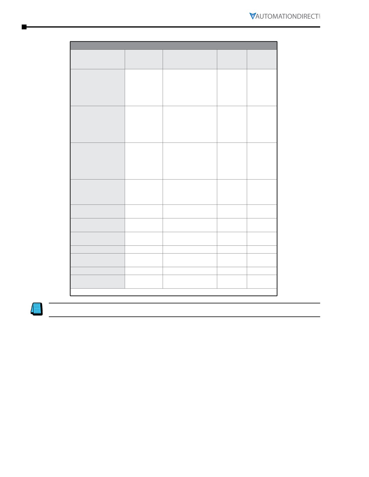
C-Flange Kits for MTC EPAct Three-Phase Motors (continued)
EPAct T-Frame Three-Phase Motor C-Flange Kits
Shipping
Part Number (1)
Fits Frame
Fits Motor (1)
Motor HP
Weight
(lb)
MTC-001-3BD12
1
MTC-001-3BD18
1
MTC-1P5-3BD18
1-1/2
MTA-CFACE-140TC
143T & 145T
6
MTC-1P5-3BD36
1-1/2
MTC-002-3BD18
2
MTC-002-3BD36
2
MTC-1P5-3BD12
1-1/2
MTC-002-3BD12
2
MTC-003-3BD18
3
MTA-CFACE-180TC
182T & 184T
12
MTC-003-3BD36
3
MTC-003-3BD36
5
MTC-005-3BD36
5
MTC-003-3BD12
3
MTC-005-3BD12
5
MTC-7P5-3BD18
7-1/2
MTA-CFACE-210TC
213T & 215T
12
MTC-7P5-3BD36
7-1/2
MTC-010-3BD18
10
MTC-010-3BD36
10
MTC-7P5-3BD12
7-1/2
MTC-010-3BD12
10
MTA-CFACE-250TC
254T & 256T
24
MTC-015-3BD18
15
MTC-020-3BD18
20
MTC-25-3BD18
25
MTA-CFACE-280TC
284T & 286T
30
MTC-30-3BD18
30
MTC-40-3BD18
40
MTA-CFACE-320TC
324T & 326T
48
MTC-50-3BD18
50
MTC-60-3BD18
60
MTA-CFACE-360TC
364T & 365T
50
MTC-75-3BD18
75
MTA-CFACE-400TC
405T
MTC-100-3BD18
100
123
MTC-125-3BD18
125
MTA-CFACE-444TC
444T & 445T
133
MTC-150-3BD18
150
MTA-CFACE-447TC
445/7T
MTC-200-3BD18
200
133
MTC-250-3D18
250
MTA-CFACE-449TC
449T
147
MTC-300-3D18
300
1) MTA-CFACE C-flange kits will NOT fit MTCP2 Premium-Efficiency motors.
Authorized EASA service centers are equipped with the necessary equipment to quickly and inexpensively
install C-Face kits. Visit the EASA website at www.easa.com to find the nearest authorized service center.
Page 6-48
Chapter 6: Legacy Motors
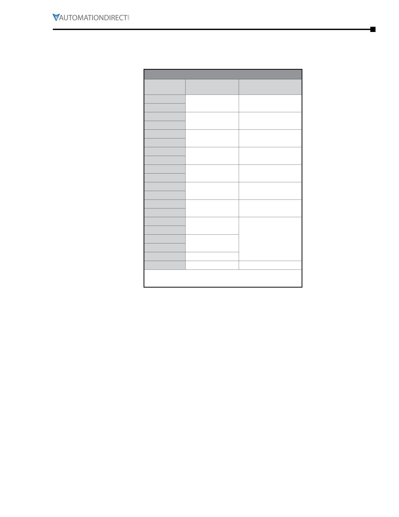
MTC Motors Bearing Size Information
All IronHorse® cast-iron motors use premium name-brand bearings (NSK, NTN, or SKF). Below is a bearing
size chart listing the type of bearings used in each frame size of IronHorse MTC motors. The bearing types
are also listed on the motor nameplate.
MTC Motors Bearing Size Chart
Opposite Drive End
Frame Size *
Drive End Bearing
Bearing
143T
6205-ZZ
6205-ZZ
145T
182T
6306-ZZ
6206-ZZ
184T
213T
6308-ZZ
6308-ZZ
215T
254T
6309
6209
256T
284T
6311
6309
286T
324T
6312
6311
326T
364T
6313
6312
365T
404T
NU316
405T
444T
6313
NU318
445T
445/7T
NU319
449T
NU320
6320
* TC-frame motors have the same bearings as the
comparable T-frame motors.
IronHorse® General Purpose
AC Motors User Manual - 11th Ed. - 06/29/2022
Page 6-49
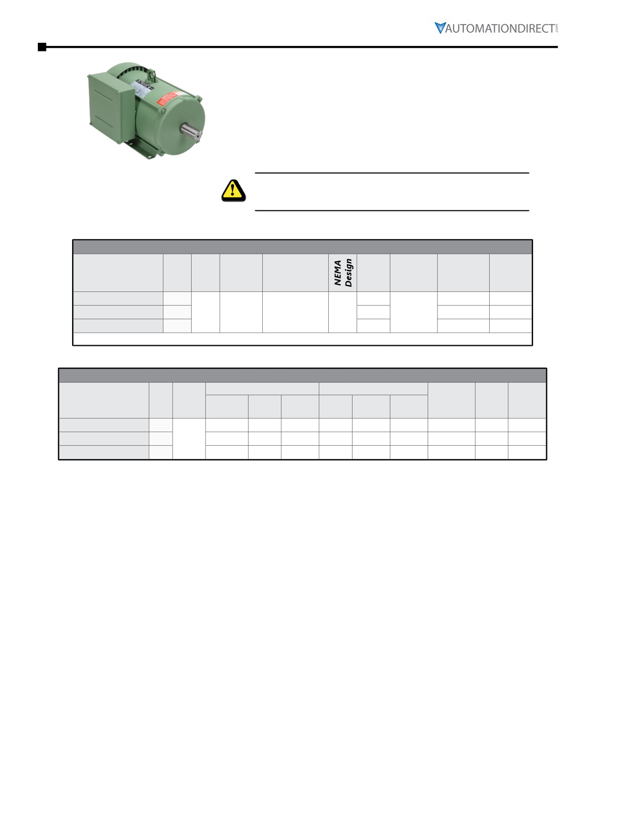
Chapter 6: Legacy Motors
MTF F
-D T-F
S ngle-Phase Motors - Features and Specifications
IronHorse® single-phase farm-duty motors are available from
2hp to 5hp. All models have a TEFC housing (steel frame
with iron end bells) that is fully gasketed for use in dirty
environments. All motors are NEMA L design.
All models include a class-10 manual-reset locked-rotor
thermal protector (motor thermal overload protection must
be provided separately).
We recommend disconnecting power to the motor before reseting the
thermal protector. Do not reset more than twice in succession. The
motor must cool to 40°C (104°F) before a third reset.
Cast-Iron T-Frame 1-Phase Farm-Duty Motor Specifications
Motor Specifications - Single-Phase Farm-Duty Motors (60Hz)
Approx
Base
NEMA
F.L. Amps
Part Number
HP
Voltage*
Service Factor
Housing
Weight
RPM
Frame
@ 230VAC
(lb)
MTF-002-1C18-182
2
182T
8.5
74
230VAC
1.15 @ 230VAC
TEFC
MTF-003-1C18
3
1800
L
184T
12.9
85
±10%
1.0 @ 208VAC
IP55
MTF-005-1C18
5
184T
21.2
105
* Operate on 230VAC +/- 10% (1.15 @ 230VAC; 1.0 S.F. @ 208V), single-phase power only.
Cast-Iron T-Frame 1-Phase Farm-Duty Motor Performance Data
Performance Data - Single-Phase Farm-Duty Motors (60Hz)
Current @ 230V (Amps)
Torque (lb·ft)
F.L.
F.L.
Rotor
F.L.
Part Number
HP
230V
Full
Locked
Full
Locked
Break
Efficiency
Power
Inertia
RPM
No Load
Load
Rotor
Load
Rotor
down
(%)
Factor
(lb·ft2)
MTF-002-1C18-182
2
2.7
8.5
70.0
6.04
20.54
15.10
82.5
0.92
0.35
MTF-003-1C18
3
1725
3.9
12.9
95.0
9.11
32.80
23.69
81.5
0.93
0.60
MTF-005-1C18
5
6.6
21.2
160.0
15.30
58.14
36.72
81.0
0.90
0.81
Page 6-50
Chapter 6: Legacy Motors
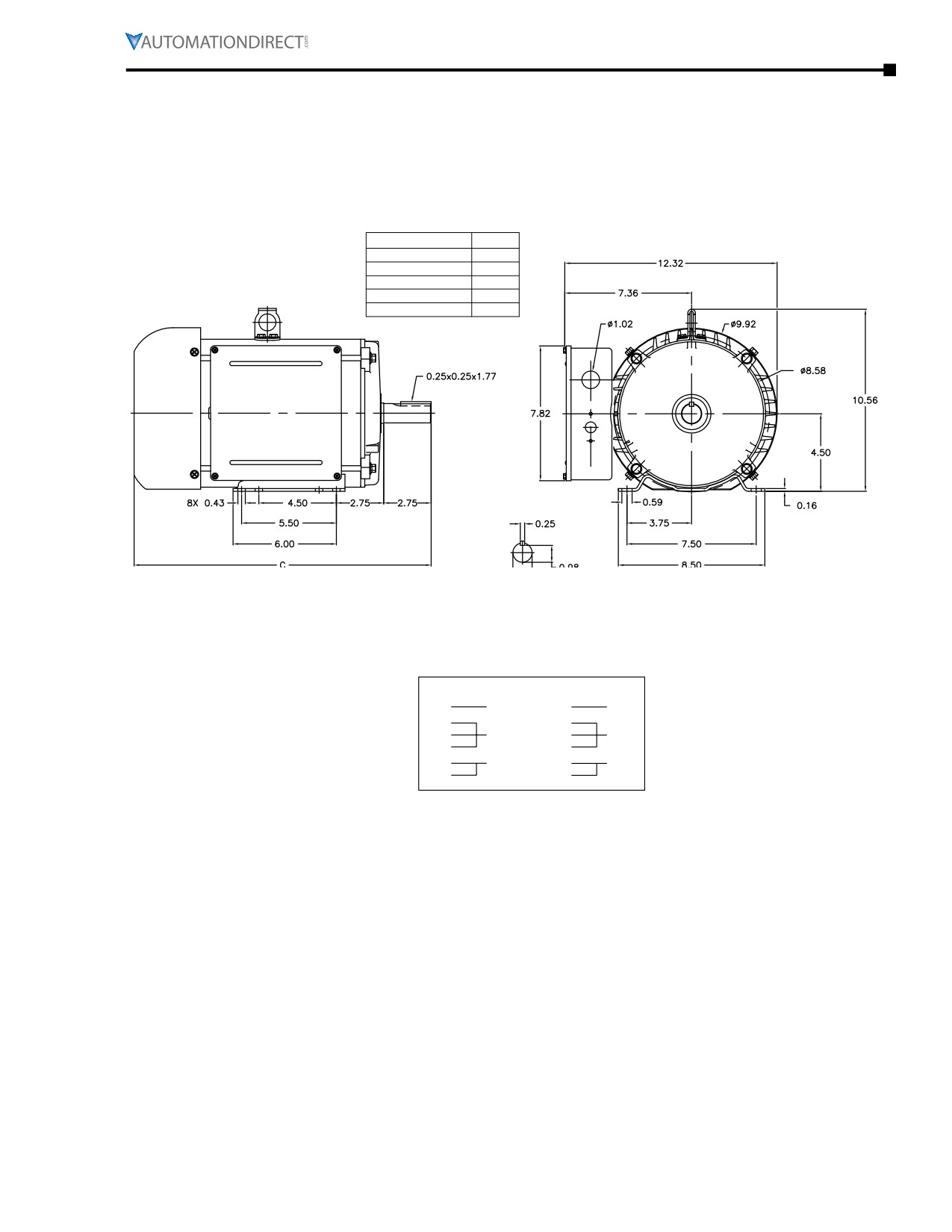
Motor Dimensions
(Dimensions = inches)
MTF T-Frame Single-phase Farm-Duty Motor Dimensions
PART NUMBER
DIM. C
MTF2-002-1B18-182
18.6
MTF2-003-1B18
18.6
MTF2-005-1B18
18.6
MTF2-7P5-1B18-215
20.46
MTF2-010-1B18
20.46
Terminal and Wiring Diagrams
MTF Farm-Duty Motors
2-5hp 1Ø Farm-Duty models ; 6-Lead, 230 VAC
CCW - ODE
CW - ODE
(P1)
LINE 1
(P1)
LINE 1
(T1)
(T1)
(P2)
INS
(P2)
INS
(T5)
(T8)
(T8)
LINE 2
(T5)
LINE 2
(T4)
(T4)
IronHorse® General Purpose
AC Motors User Manual - 11th Ed. - 06/29/2022
Page 6-51
Chapter 6: Legacy Motors
Replacement Parts
Capacitors and Centrifugal Switches for IronHorse® Single-Phase Motors
Single phase motors use capacitors to provide starting torque when power is first applied to the motor.
When the motor begins to turn, the start capacitor is no longer need and is taken out of the circuit by a
centrifugal switch. In addition to the start capacitor, 1-1/2 hp and larger IronHorse single-phase motors
have run capacitors to allow the motor to develop higher running torque and greater efficiency. Run
capacitors also help improve the motor power factor.
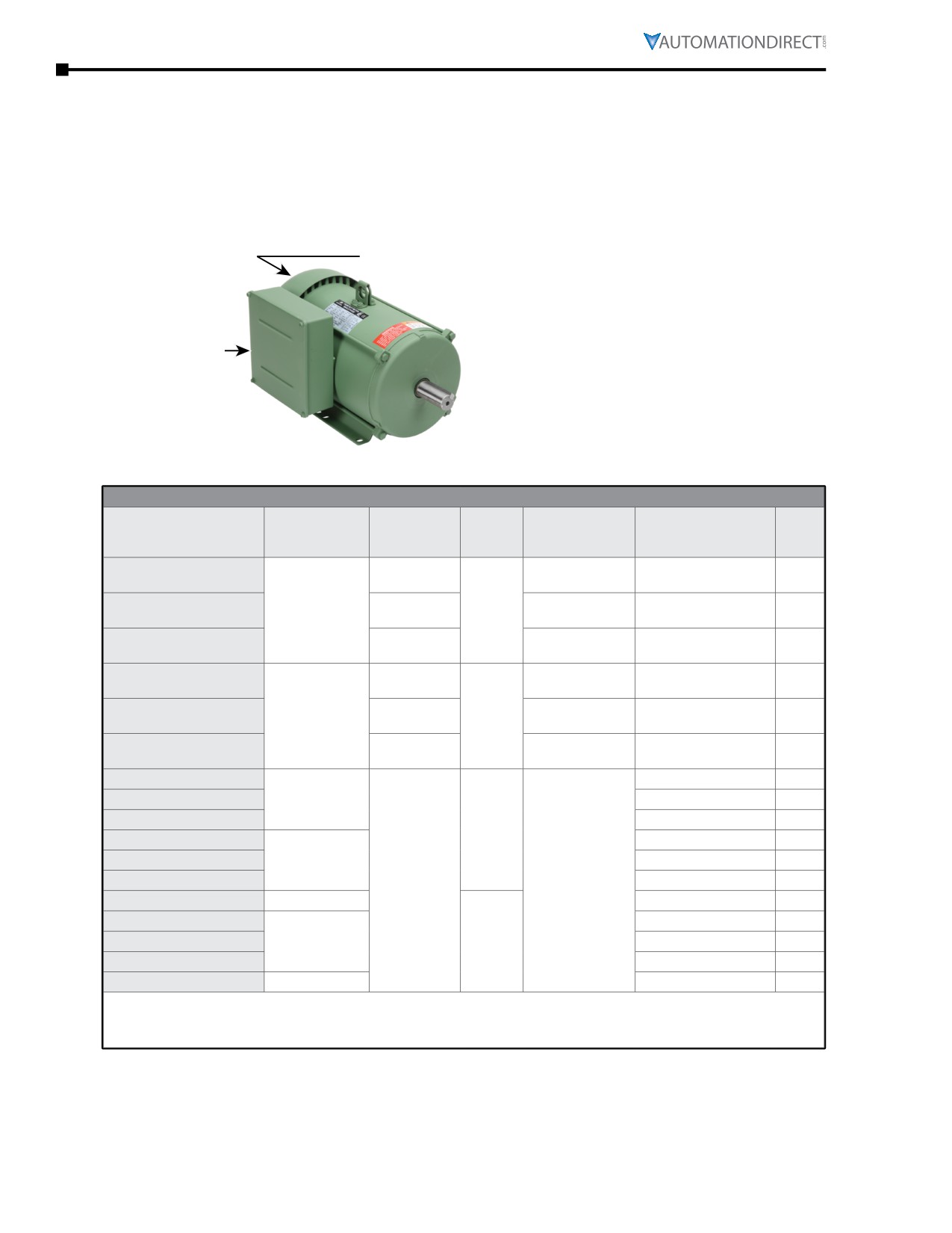
MTF Accessory Locations
Centrifugal Switch
Fan Shroud
Fan
Junction Box
Start Capacitor
Run Capacitor
Manual O/L Switch
Note: Not all accessories
are applicable to all MTF2 motors
Spare/Replacement Parts for MTF Single-Phase Farm-Duty Motors
MTF Single-Phase Motor Spare/Replacement Parts *
Dimension
Accessory
Capacitance
Rated
Applicable
Motor
Part Number
Height x Ø
Type
(µF)
Voltage
Motor Number
HP
(in[mm])
3.39 x 1.81
MTA-CAP-16
200
MTF-002-1C18-182
2
[86.1 x 46.0]
Start
3.39 x 1.81
MTA-CAP-17
300
300
MTF-003-1C18
3
capacitor
[86.1 x 46.0]
4.33 x 1.97
MTA-CAP-18
500
MTF-005-1C18
5
[110.0 x 50.0]
3.96 x 1.77
MTA-CAP-19
35
MTF-002-1C18-182
2
[100.6 x 45.0]
Run
3.96 x 1.97
MTA-CAP-20
40
450
MTF-003-1C18
3
capacitor
[100.6 x 50.0]
4.17 x 1.97
MTA-CAP-21
50
MTF-005-1C18
5
[106.0 x 50.0]
MTA-CSW-05
MTF-002-1C18-182
2
Centrifugal
MTA-CSW-06
MTF-003-1C18
3
switch
MTA-CSW-07
MTF-005-1C18
5
250
MTA-MOL-1**
MTF-002-1C18-182
2
Manual overload
MTA-MOL-2**
MTF-003-1C18
3
switch
MTA-MOL-3**
n/a
MTF-005-1C18
5
MTAF-JBOX-180
Junction box
MTF-xxx-1C18-xxx
all
MTAF-FAN-182
MTF-002-1C18-182
2
MTAF-FAN-184
Fan
n/a
MTF-003-1C18
3
MTAF-FAN-184-2
MTF-005-1C18
5
MTAF-SHROUD-180
Fan shroud
MTF-xxx-1C18-xxx
all
* These accessories are spare/replacement components only for IronHorse MTF series single-phase farm-duty motors.
** MTA-MOL-1 = JOEMEX TC4-0-E-1-44, V07-1; MTA-MOL-2 = JOEMEX TC4-0-E-1-44, V06-1;
MTA-MOL-3 = JOEMEX TC4-0-E-1-40, V08-1
Page 6-52
Chapter 6: Legacy Motors
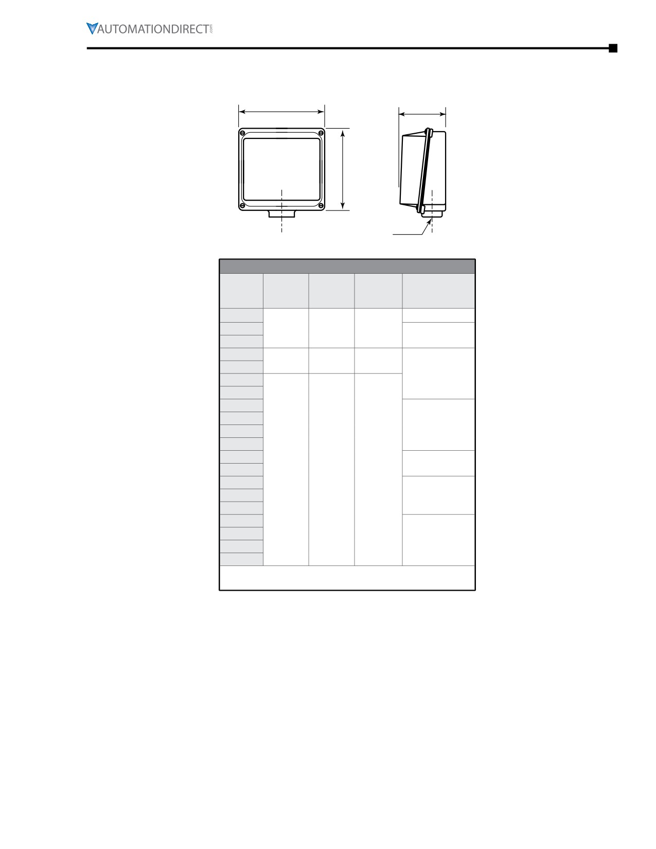
Junction Box Dimensions
XD
HH
XC
AA
Junction Box Dimensions (in)
AA
Frame
XD
XC
HH
(Conduit Hole)
Size *
(Width)
(Height)
(Depth)
(NPT)
56
1/2
143T
n/a
n/a
n/a
3/4
145T
182T
7.8
7.8
2.7
184T
1
213T
215T
254T
256T
1-1/2
284T
286T
324T
2
326T
n/a
n/a
n/a
364T
365T
3
405T
444T
445T
3 (2 openings)
445/7T
449T
* TC-frame motors have the same junction boxes as the
comparable T-frame motors.
IronHorse® General Purpose
AC Motors User Manual - 11th Ed. - 06/29/2022
Page 6-53