Ironhorsem General Purpose AC Motors Manual Number: IH-MT-AC_UMW Motor Series: MTR (11th Ed. – 06/29/2022) - page 9
Chapter 6: Legacy Motors
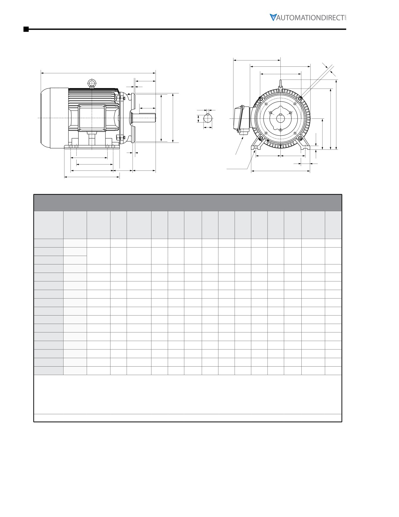
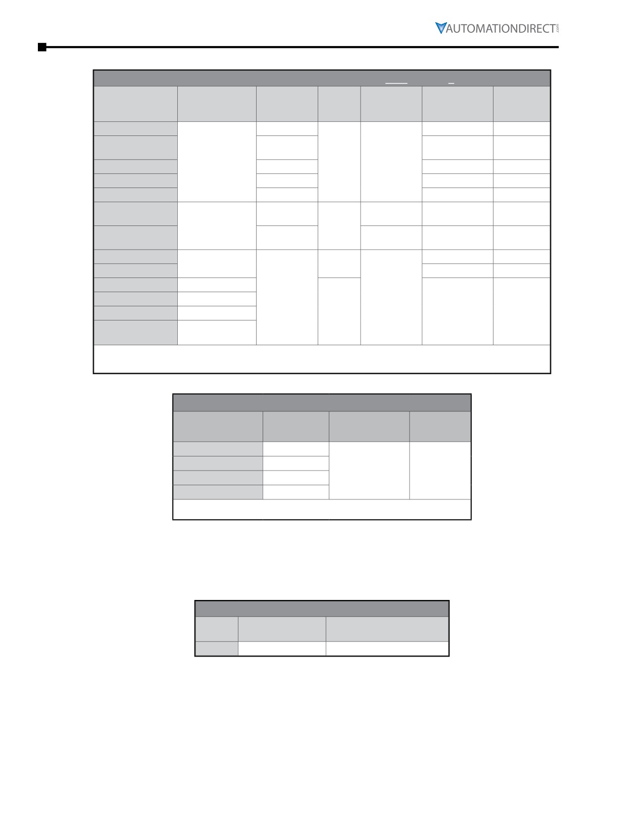
MTCP Motor Dimensions (continued) - (Dimensions = inches)
MTCP Premium-Efficiency TC-Frame Three-Phase Motor Dimensions
AB
BF
P
C
AJ
AH
***
***
L***
BB
ES
L***
S
AK
BD
R
U
D
G
BC
AA**
E
E
F1*
F1*
J
H (hole)
F2
BA
N-W
A
B
** F1 mounting shown. Some frame sizes are F1/F2 convertible.
* Various frame sizes have 2 or 4 mounting holes
per mounting foot (one mounting foot per side).
*** Frames 143TC and 145TC have no lifting eyelet.
Dimensions [inches, except as noted]
Premium-Efficiency Three-Phase TC-Frame Motors - 1800 rpm
Part #
MTCP-
NEMA
HP
A
AA**
AB
AH
AJ
AK
B
BA
BB
BC
BD
BF
C
xxx-
Frame
3BD18C
-001-
1
143TC
7
3/4”NPT
6.89
1.96
5.875
4.5
5.1
2.25
0.16
0.29
6.5
3/8-16
12.5
-1P5-
1-1/2
145TC
7
3/4”NPT
6.89
1.96
5.875
4.5
6
2.25
0.16
0.29
6.5
3/8-16
13.5
-002-
2
-003-
3
182TC
8.9
1” NPT
7.45
2.37
7.25
8.5
6.3
2.75
0.25
0.38
9
1/2-13
15.1
-005-
5
184TC
8.9
1” NPT
7.45
2.37
7.25
8.5
7.1
2.75
0.25
0.38
9
1/2-13
16.1
-7P5-
7-1/2
213TC
10.5
1” NPT
8.63
2.87
7.25
8.5
7.5
3.5
0.25
0.51
9
1/2-13
18.9
-010-
10
215TC
10.5
1” NPT
8.63
2.87
7.25
8.5
9
3.5
0.25
0.51
9
1/2-13
20.5
-015-
15
254TC
12.3
1.5”NPT
12.0
3.75
7.25
8.5
10.3
4.25
0.25
0.25
10
1/2-13
23.3
-020-
20
256TC
12.3
1.5”NPT
12.0
3.75
7.25
8.5
12.4
4.25
0.25
0.25
10
1/2-13
25.1
-025-
25
284TC
13.7
1.5”NPT
13.7
4.38
9
10.5
12.2
4.75
0.25
0.25
11.25
1/2-13
26.6
-030-
30
286TC
13.7
1.5”NPT
13.7
4.38
9
10.5
13.7
4.75
0.25
0.24
11.25
1/2-13
28.2
-040-
40
324TC
15.3
2” NPT
15.3
5
11
12.5
12.6
5.25
0.25
0.24
14
5/8-11
30.0
-050-
50
326TC
15.3
2” NPT
15.3
5
11
12.5
14.0
5.25
0.25
0.25
14
5/8-11
31.2
-060-
60
364TC
17.0
3” NPT
17.3
5.62
11
12.5
14.6
5.88
0.25
0.25
14
5/8-11
32.6
-075-
75
365TC
17.0
3” NPT
17.3
5.62
11
12.5
15.6
5.88
0.25
0.25
14
5/8-11
34.1
-100-
100
405TC
20
3” NPT
18.1
7
11
12.5
17.8
6.62
0.25
0.25
15.5
5/8-11
38.4
* Various frame sizes have 2 or 4 mounting holes per mounting foot.
** AA dimension is conduit fitting size. F1 mounting shown; some frame sizes are F1/F2 convertible; refer to T-frame
“Motor Specifications” table.
(F2 mounting = conduit entrance on right side facing shaft.)
*** Frame sizes 143T(C) and 145T(C) have no lifting eyelet.
**** TABLE CONTINUED NEXT PAGE (for dimensions D-U) ****
Page 6-14
Chapter 6: Legacy Motors
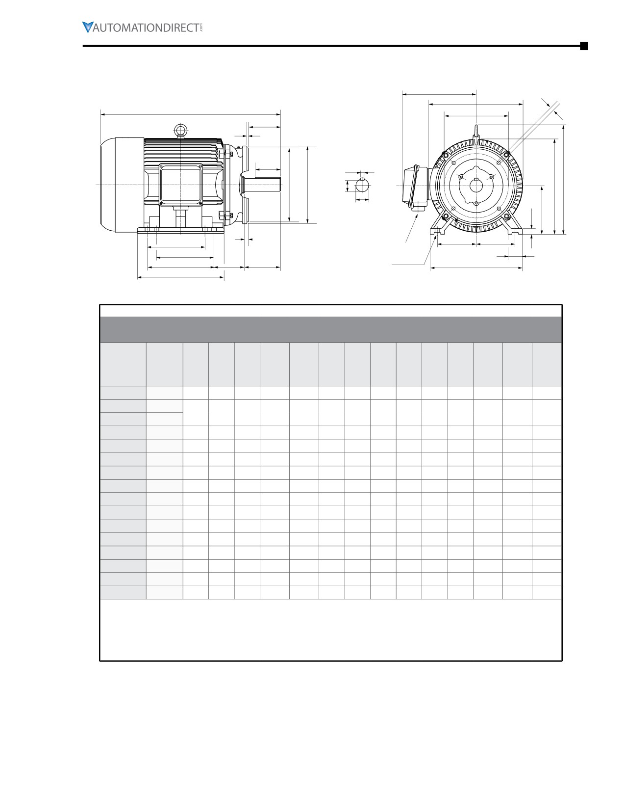
MTCP Motor Dimensions (continued) - (Dimensions = inches)
MTCP Premium-Efficiency TC-Frame Three-Phase Motor Dimensions (continued)
AB
BF
P
C
AJ
AH
***
***
L***
BB
ES
L***
S
AK
BD
R
U
D
G
BC
AA**
E
E
F1*
F1*
J
H (hole)
F2
BA
N-W
A
B
** F1 mounting shown. Some frame sizes are F1/F2 convertible.
* Various frame sizes have 2 or 4 mounting holes
per mounting foot (one mounting foot per side).
*** Frames 143TC and 145TC have no lifting eyelet.
**** TABLE CONTINUED FROM PREVIOUS PAGE (for dimensions A-C) ****
Dimensions [inches, except as noted]
Premium-Efficiency Three-Phase TC-Frame Motors - 1800 rpm
Part #
MTCP-
HP
D
E
ES
F1*
F2*
G
H
J
N-W
L
P
R
S
U
xxx-
3BD18C
-001-
1
3.5
2.75
1.41
n/a
4
0.47
0.34
1.45
2.25
6.9
7.2
0.771
0.188
0.875
-1P5-
1-1/2
3.5
2.75
1.41
4
5
0.47
0.34
1.45
2.25
6.9
7.2
0.771
0.188
0.875
-002-
2
-003-
3
4.5
3.75
1.78
n/a
4.5
0.52
0.41
1.97
2.75
10.4
9.0
0.986
0.25
1.125
-005-
5
4.5
3.75
1.78
4.5
5.5
0.52
0.41
1.97
2.75
10.4
9.0
0.986
0.25
1.125
-7P5-
7-1/2
5.25
4.25
2.41
n/a
5.5
0.78
0.41
2.36
3.38
12.3
10.8
1.201
0.312
1.375
-010-
10
5.25
4.25
2.41
5.5
7
0.78
0.41
2.36
3.38
12.3
10.8
1.201
0.312
1.375
-015-
15
6.25
5
2.91
n/a
8.25
0.87
0.53
2.40
4
15.1
14.4
1.416
0.375
1.625
-020-
20
6.25
5
2.91
8.25
10
0.87
0.53
2.40
4
15.1
14.4
1.416
0.375
1.625
-025-
25
7
5.5
3.28
n/a
9.5
0.98
0.53
2.68
4.62
16.5
16.0
1.591
0.5
1.875
-030-
30
7
5.5
3.28
9.5
11
0.98
0.53
2.68
4.62
16.5
16.0
1.591
0.5
1.875
-040-
40
8
6.25
3.91
n/a
10.5
0.98
0.66
2.76
5.25
18.3
17.5
1.854
0.5
2.125
-050-
50
8
6.25
3.91
10.5
12
0.98
0.66
2.76
5.25
18.3
17.5
1.845
0.5
2.125
-060-
60
9
7
4.28
n/a
11.25
1.10
0.66
3.15
5.88
21.0
19.1
2.021
0.625
2.375
-075-
75
9
7
4.28
11.25
12.25
1.10
0.66
3.15
5.88
21.0
19.1
2.021
0.625
2.375
-100-
100
10
8
5.65
12.25
13.75
1.18
0.81
3.15
7.25
23.5
21.4
2.45
0.75
2.875
* Various frame sizes have 2 or 4 mounting holes per mounting foot.
** AA dimension is conduit fitting size. F1 mounting shown; some frame sizes are F1/F2 convertible; refer to
T-frame “Motor Specifications” table.
(F2 mounting = conduit entrance on right side facing shaft.)
*** Frame sizes 143T(C) and 145T(C) have no lifting eyelet.
IronHorse® General Purpose
AC Motors User Manual - 11th Ed. - 06/29/2022
Page 6-15
Chapter 6: Legacy Motors
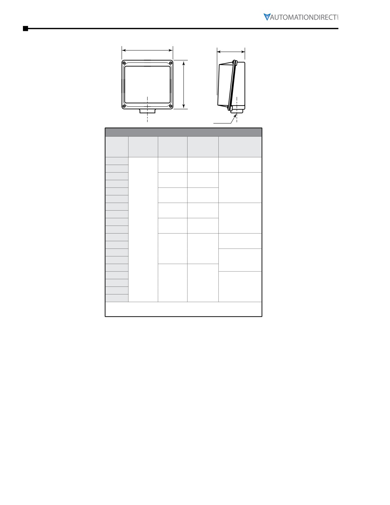
MTCP Junction Box Dimensions
XD
HH
XC
AA
Junction Box Dimensions (in)
AA
Frame
XD
XC
HH
(Conduit Hole)
Size *
(Width)
(Height)
(Depth)
(NPT)
143T
4.5
2.3
3/4
145T
182T
5.0
2.5
184T
1
213T
5.3
2.6
215T
254T
7.3
3.3
256T
1-1/2
284T
10.4
6.0
286T
11.3
324T
2
326T
10.8
5.3
364T
365T
3
405T
444T
445T
11.7
7.1
3 (2 openings)
445/7T
449T
* TC-frame motors have the same junction boxes as the
comparable T-frame motors.
Page 6-16
Chapter 6: Legacy Motors
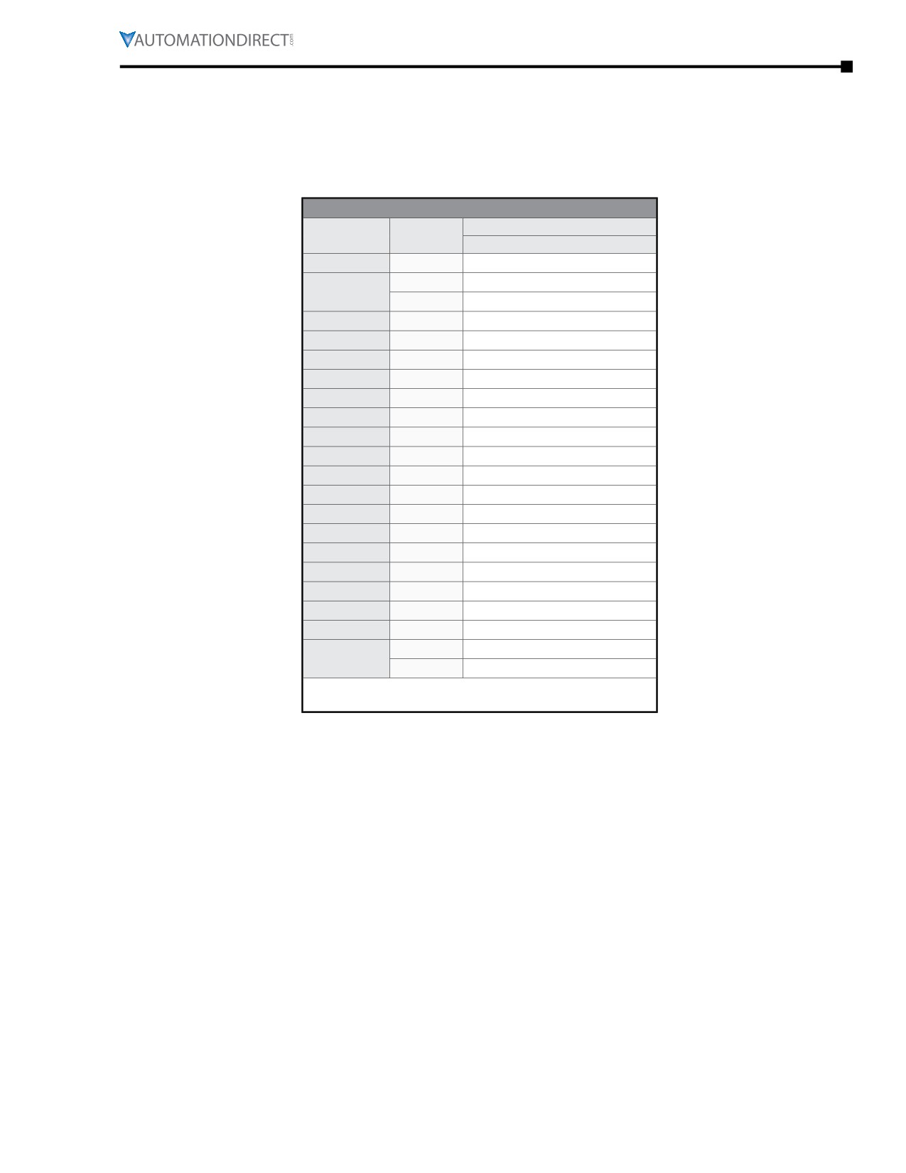
MTCP Decibel Levels
The decibel (sound) level of an IronHorse® motor should be measured after initial startup, after 30 days,
and after six months of use. Decibel levels should remain fairly consistent and can be an indication
of misalignment and premature bearing wear. If the measured decibel level for your IronHorse model
exceeds the value listed below by more than 10%, contact AutomationDirect or a local motor service
technician found at www.easa.com.
MTCP Average T-Frame Decibel Levels
Noise Level: Lw dB(A) @ 1m
Frame Size *
HP
MTCP
143T
1
70.0
1-1/2
70.0
145T
2
70.0
182T
2
-
182T
3
74.0
184T
5
74.0
213T
7-1/2
79.0
215T
10
79.0
254T
15
84.0
256T
20
84.0
284T
25
88.0
286T
30
88.0
324T
40
89.0
326T
50
89.0
364T
60
95.0
365T
75
95.0
405T
100
98.0
444T
125
100
445T
150
100
445/7T
200
103
250
105.0
449T
300
105.0
* TC-frame motors have the same sound ratings as the
comparable T-frame motors.
IronHorse® General Purpose
AC Motors User Manual - 11th Ed. - 06/29/2022
Page 6-17
Chapter 6: Legacy Motors
Spare/Replacement Parts for MTCP Premium-Efficiency Three-Phase Motors
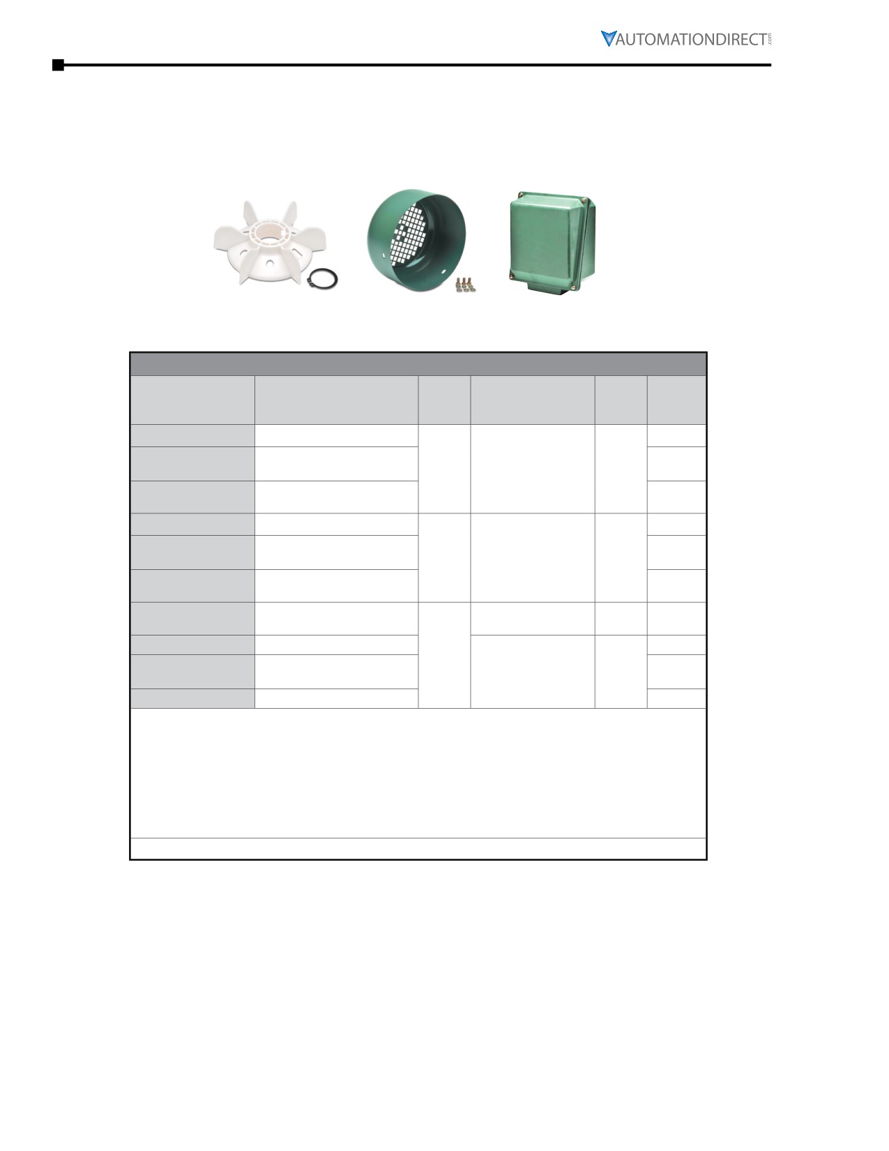
IronHorse junction boxes, TEFC fans, and TEFC fan shrouds are available as direct replacement parts for
MTCP motors.
These parts are field installable, and include installation instructions.
Fan
Fan Shroud
Junction Box
MTCP Premium-Efficiency Three-Phase Motor Replacement Parts
Product
Fits
Fits PE Motor
Motor
Part Number (1)
Description (2)(3)(4)
Weight
Frame
Number (1)
HP
(lb)
MTAP-FAN-140
Replacement Fan
MTCP-001-3BD12
1
0.3
MTCP-001-3BD18(C)
1
MTAP-
143
Replacement Fan Shroud
MTCP-1P5-3BD18(C)
1-1/2
1.1
SHROUD-140
&
MTCP-1P5-3BD36
1-1/2
145
MTCP-002-3BD18(C)
2
MTAP-JBOX-140
Replacement Junction Box
2.6
MTCP-002-3BD36
2
MTAP-FAN-180
Replacement Fan
MTCP-1P5-3BD12
1-1/2
0.3
MTCP-002-3BD12
2
MTAP-
182
Replacement Fan Shroud
MTCP-003-3BD18(C)
3
1.5
SHROUD-180
&
MTCP-003-3BD36
3
184
MTCP-005-3BD18(C)
5
MTAP-JBOX-180
Replacement Junction Box
3.1
MTCP-005-3BD36
5
Replacement Fan
MTCP-7P5-3BD36
7-1/2
MTAP-FAN-210-2
0.3
(for 2-pole motors)
MTCP-010-3BD36
10
213
MTAP-FAN-210
Replacement Fan (4&6-pole)
0.3
MTCP-003-3BD12
3
&
MTAP-
MTCP-005-3BD12
5
Replacement Fan Shroud
215
2.3
SHROUD-210
MTCP-7P5-3BD18(C)
7-1/2
MTCP-010-3BD18(C)
10
MTAP-JBOX-210
Replacement Junction Box
3.4
1) These MTAP replacement components fit only MTCP Premium-Efficiency motors;
they will NOT fit MTC EPAct motors.
2) Replacement Fans include fan, snap ring, and instructions.
3) Replacement Fan Shrouds include shroud, bolts w/washers, rubber plug, and
instructions.
4) Replacement Junction Boxes include gasketed base & cover assembly, base gasket,
base bolts, and instructions.
*** TABLE CONTINUED NEXT PAGE ***
Page 6-18
Chapter 6: Legacy Motors
Spare/Replacement Parts for MTCP Premium-Efficiency 3-Phase Motors (continued)
*** TABLE CONTINUED FROM PREVIOUS PAGE ***
MTCP Premium-Efficiency Three-Phase Motor Replacement Parts
Product
Fits
Fits PE Motor
Motor
Part Number (1)
Description (2)(3)(4)
Weight
Frame
Number (1)
HP
(lb)
Replacement Fan
MTCP-015-3BD36
15
MTAP-FAN-250-2
0.3
(for 2-pole motors)
MTCP-020-3BD36
20
254
MTAP-FAN-250
Replacement Fan (4&6-pole)
MTCP-7P5-3BD12
7-1/2
0.3
&
MTCP-010-3BD12
10
MTAP-SHROUD-250
Replacement Fan Shroud
256
4.5
MTCP-015-3BD18(C)
15
MTAP-JBOX-250
Replacement Junction Box
MTCP-020-3BD18(C)
20
7.0
MTAP-FAN-280
Replacement Fan
MTCP-015-3BD12
15
0.5
284
MTCP-020-3BD12
20
MTAP-SHROUD-280
Replacement Fan Shroud
&
6.5
MTCP-025-3BD18(C)
25
286
MTAP-JBOX-280
Replacement Junction Box
MTCP-030-3BD18(C)
30
7.0
MTAP-FAN-320
Replacement Fan
0.6
324
MTCP-040-3BD18(C)
40
MTAP-SHROUD-320
Replacement Fan Shroud
&
8.3
MTCP-050-3BD18(C)
50
326
MTAP-JBOX-320
Replacement Junction Box
22.3
MTAP-FAN-360
Replacement Fan
0.6
364
MTCP-060-3BD18(C)
60
MTAP-SHROUD-360
Replacement Fan Shroud
&
9.0
MTCP-075-3BD18(C)
75
365
MTAP-JBOX-360
Replacement Junction Box
22.3
MTAP-FAN-400
Replacement Fan
1.1
MTAP-SHROUD-400
Replacement Fan Shroud
405
MTCP-100-3BD18(C)
100
15.8
MTAP-JBOX-400
Replacement Junction Box
30.0
MTAP-FAN-440
Replacement Fan
444
2.0
MTCP-125-3BD18
125
445
MTAP-SHROUD-440
Replacement Fan Shroud
MTCP-150-3BD18
150
17.5
&
MTCP-200-3BD18
200
MTAP-JBOX-440
Replacement Junction Box
447
40.0
1) These MTAP replacement components fit only MTCP Premium-Efficiency motors; they
will NOT fit MTC EPAct motors.
2) Replacement Fans include fan, snap ring, and instructions.
3) Replacement Fan Shrouds include shroud, bolts w/washers, rubber plug, and
instructions.
4) Replacement Junction Boxes include gasketed base & cover assembly, base gasket, base
bolts, and instructions.
IronHorse® General Purpose
AC Motors User Manual - 11th Ed. - 06/29/2022
Page 6-19
Chapter 6: Legacy Motors
MTCP Bearing Size Information
All IronHorse® cast-iron motors use premium name-brand bearings (NSK, NTN, or SKF). Below is a bearing
size chart listing the type of bearings used in each frame size of IronHorse MTCP motors. The bearing types
are also listed on the motor nameplate.
MTCP Bearing Size Chart
Frame
Drive End Bearing
Opposite Drive End Bearing
Size *
143T
6205-ZZ
6205-ZZ
145T
182T
6306-ZZ
6306-ZZ
184T
213T
6308-ZZ
6306-ZZ
215T
254T
6309
6308
256T
284T
6311
6309
286T
324T
6312
6312
326T
364T
6313
6312
365T
404T
-
NU316
405T
6313
444T
NU318
445T
6314
445/7T
NU319
449T
NU320
-
* TC-frame motors have the same bearings as the comparable
T-frame motors.
Page 6-20
Chapter 6: Legacy Motors
MTR Series Motors
MTR Features and Specifications (Single-Phase Motors)
IronHorse® single-phase 56C/56HC-frame* motors are available from 1/3 hp to 2 hp. All models have a
TEFC rolled steel frame, cast aluminum end bell and removable mounting bases.
MTR Rolled-Steel 56C-Frame 1-Phase Motor Specifications
Motor Specifications - Single-Phase 56C/56HC-Frame Motors (60Hz except as indicated)
F.L. Amps @
Base
115V/230V
Approx
HP
Voltage
Part Number
RPM
Housing
60Hz
Weight
(110/220V
(lb)
50Hz)
@ 60Hz (50Hz)
1800 RPM
MTR-P33-1AB18
1/3
IP43
6.6 / 3.3
26
TEFC
MTR-P50-1AB18
1/2
8.8 / 4.4
28
rolled steel
MTR-P75-1AB18
3/4
56C
11.0 / 5.5
32
frame
1800
115/208-230
1.15
N
flange
MTR-001-1AB18
1
Cast AL end
13.6 / 6.8
38
mount
bell
MTR-1P5-1AB18
1-1/2
F1 conduit
15.2 / 7.6
45
box location
3600 RPM
IP43
TEFC
rolled steel
frame
MTR-1P5-1AB36
1-1/2
3600
115/208-230
1.15
N
56C
14.2 / 7.1
37
Cast AL end
bell
F1 conduit
box location
Note: Please review the AutomationDirect Terms & Conditions for warranty and service on this product.
NOTE: *56HC are suitable for 56C C-face mounting or 56, 143T, or 145T frame foot mounting dimensions.
MTR Rolled-Steel 56C-Frame 1-Phase Motor Performance Data
Performance Data - Single-Phase 56C/56HC-Frame Motors
(230V / 60Hz data except as indicated)
F.L.
Current @ 115V/230V
HP
Torque (lb·ft)
RPM
(Amps)
Rotor
Part Number
Inertia
230V
@
Locked
Full
Locked
Break
(lb·ft2)
No
Full Load
60Hz (50Hz)
Rotor
Load
Rotor
down
Load
1800 RPM
MTR-P33-1AB18
1/3
2.2
6.6 / 3.3
31 / 18
1.02
3.06
2.81
56.0
0.62
0.075
MTR-P50-1AB18
1/2
2.93
8.8 / 4.4
37 / 21
1.52
4.56
4.18
57.0
0.63
0.080
MTR-P75-1AB18
3/4
1725
3.67
11.0 / 5.5
55 / 32
2.29
6.30
5.73
65.0
0.65
0.095
MTR-001-1AB18
1
4.53
13.6 / 6.8
75 / 43
3.04
8.36
7.60
68.0
0.66
0.120
MTR-1P5-1AB18
1-1/2
5.07
15.2 / 7.6
120 / 65
4.57
11.43
10.28
71.0
0.75
0.142
3600 RPM
MTR-1P5-1AB36
1-1/2
3450
3.0
14.2 / 7.1
116 / 58
2.2
7.5
5.4
72.0
0.9
0.03
IronHorse® General PurposeAC Motors User Manual - 11th Ed. - 06/29/2022
Page 6-21
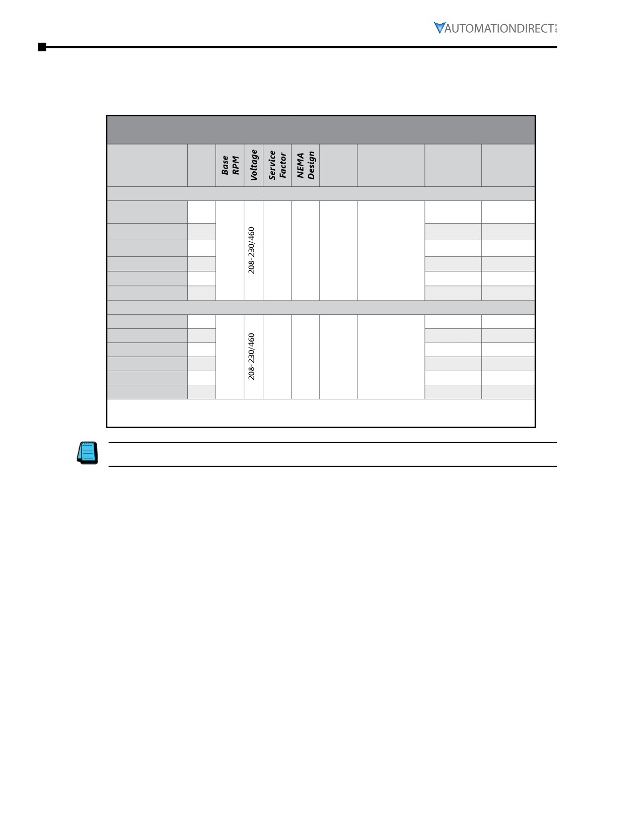
Chapter 6: Legacy Motors
MTR Features and Specifications (Three-Phase Motors)
IronHorse® rolled steel 56C/56HC-frame* three-phase motors are available from 1/3 hp to 3 hp. All models
have a TEFC frame, cast aluminum end bell and removable mounting bases.
MTR Rolled-Steel 56C/56HC-Frame 3-Phase Motor Specifications - 1800 & 3600 rpm
Motor Specifications - MTR 3-Phase 56C/56HC-Frame Motors -
1800 & 3600 rpm
F.L. Amps
Approx
Part
NEMA
HP
Housing
@
Weight
Number
Frame
230V/460V
(lb)
1800 RPM
MTR-P33-3BD18
1/3
1.6 / 0.8
23
TEFC rolled
MTR-P50-3BD18
1/2
steel frame
2.0 / 1.0
24
56C
Cast
MTR-P75-3BD18
3/4
1800
1.15
B
flange
aluminum
2.8 / 1.4
26
MTR-001-3BD18
1
mount
end bell
3.6 / 1.8
29
F1 conduit
MTR-1P5-3BD18
1-1/2
4.8 / 2.4
33
box location
MTR-002-3BD18
2
6.0 / 3.0
42
3600 RPM
MTR-P33-3BD36
1/3
1.6 / 0.8
23
TEFC rolled
MTR-P50-3BD36
1/2
steel frame
2.2 / 1.1
24
56C
Cast
MTR-P75-3BD36
3/4
2.9 / 1.5
26
3600
1.15
B
flange
aluminum
MTR-001-3BD36
1
3.6 / 1.8
28
mount
end bell
MTR-1P5-3BD36
1-1/2
F1 conduit
4.6 / 2.3
34
box location
MTR-002-3BD36
2
6.0 / 3.0
43
Note: Please review the AutomationDirect Terms & Conditions for warranty and service on
this product.
NOTE: *56HC are suitable for 56C C-face mounting or 56, 143T, or 145T frame foot mounting
dimensions.
Page 6-22
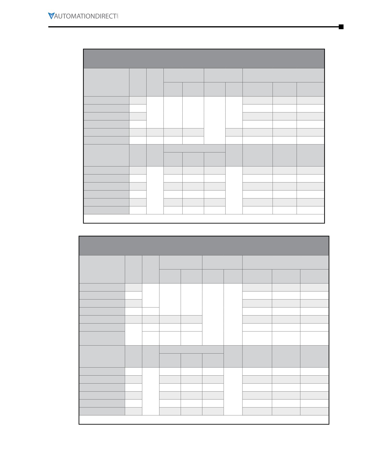
Chapter 6: Legacy Motors
MTR Rolled-Steel 56C/56HC-Frame Three-Phase Motors Features and Specifications (continued)
MTR Motor Performance Data - 1800 rpm
Performance Data - MTR/MTR2 Three-Phase 56C/56HC-Frame Motors - 1800 rpm
(460V data except as indicated)
Minimum
Maximum
Current @ 230V/460V
Part
F.L.
Speed (rpm)
Speed (rpm)
(Amps)
HP
Number
RPM
Full
Locked
CT
VT
CHP*
Safe
No Load
Load
Rotor
MTR-P33-3BD18
1/3
0.53 / 0.27
1.6 / 0.8
8 / 4
MTR-P50-3BD18
1/2
0.67 / 0.33
2.0 / 1.0
12 / 6
1725
863
345
5400
MTR-P75-3BD18
3/4
0.93 / 0.47
2.8 / 1.4
18 / 9
2700
MTR-001-3BD18
1
1.2 / 0.6
3.6 / 1.8
24 / 12
MTR-1P5-3BD18
1-1/2
1725
863
345
5400
1.5 / 0.8
4.8 / 2.4
36 / 18
MTR-002-3BD18
2
1725
863
345
5400
2.0 / 1.0
6.0 / 3.0
48 / 24
Torque (lb·ft)
F.L.
F.L.
Rotor
Part
HP
Full
Locked
Break
Efficiency
Power
Inertia
Number
Load
Rotor
-down
(%)
Factor
(lb·ft2)
MTR-P33-3BD18
1/3
1.02
2.55
2.81
67.0
0.70
0.058
MTR-P50-3BD18
1/2
1.52
3.80
4.18
69.0
0.72
0.068
MTR-P75-3BD18
3/4
2.29
5.73
6.30
71.0
0.74
0.075
n/a
n/a
MTR-001-3BD18
1
3.02
7.55
8.31
73.0
0.76
0.086
MTR-1P5-3BD18
1-1/2
4.57
10.28
11.43
75.0
0.78
0.108
MTR-002-3BD18
2
6.09
13.70
15.23
77.0
0.80
0.143
* Maximum Constant HP rpm is for direct-coupled loads.
MTR Motor Performance Data - 3600 rpm
Performance Data - Three-Phase 56C/56HC-Frame Motors - 3600 rpm
(460V data except as indicated)
Minimum Speed
Maximum
Current @ 230V/460V
Part
F.L.
(rpm)
Speed (rpm)
(Amps)
HP
Number
RPM
Locked
CT
VT
CHP*
Safe
No Load
Full Load
Rotor
MTR-P33-3BD36
1/3
1.2 / 0.59
1.6 / 0.8
9 / 5
MTR-P50-3BD36
1/2
3450
1.4 / 0.7
2.2 / 1.1
14 / 7
1725
690
MTR-P75-3BD36
3/4
1.5 / 0.75
2.9 / 1.5
17 / 8.9
MTR-001-3BD36
1
3450
1.7 / 0.85
3.6 / 1.8
25 / 13
5400
5400
MTR-1P5-3BD36
1-1/2
3450
1725
690
1.8 / 0.9
4.6 / 2.3
29 / 17
MTR-002-3BD36
3450
1725
690
3.4 / 1.7
6.0 / 3.0
57 / 30
MTRP-002-
2
3500
875
350
2.28 / 1.14
5.22 / 2.61
53/27
3BD36
Torque (lb·ft)
F.L.
F.L.
Rotor
Part
HP
Full
Locked
Break
Efficiency
Power
Inertia
Number
Load
Rotor
-down
(%)
Factor
(lb·ft2)
MTR-P33-3BD36
1/3
0.50
3.0
3.0
57.0
0.71
0.084
MTR-P50-3BD36
1/2
0.75
4.4
4.5
62.0
0.71
0.095
MTR-P75-3BD36
3/4
1.13
6.0
5.8
67.0
0.78
0.107
n/a
n/a
MTR-001-3BD36
1
1.50
7.9
7.1
69.0
0.82
0.122
MTR-1P5-3BD36
1-1/2
2.25
11.2
8.4
72.0
0.85
0.143
MTR-002-3BD36
2
3.06
18.9
13.4
75.0
0.78
0.188
* Maximum Constant HP rpm is for direct-coupled loads.
IronHorse® General Purpose
AC Motors User Manual - 11th Ed. - 06/29/2022
Page 6-23
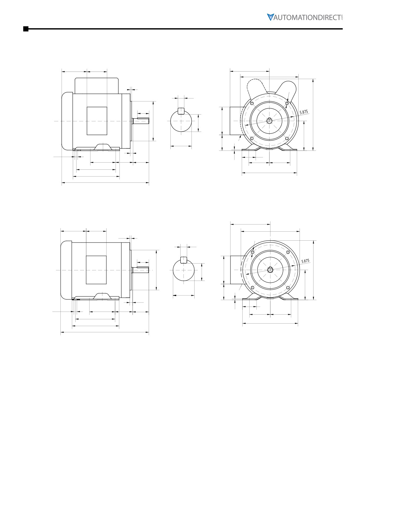
Chapter 6: Legacy Motors
MTR Motor Dimensions
(Dimensions = inches)
MTR 56C-Frame Single-phase Rolled-steel Motor Dimensions
2.85
3.23
5.35
6.9
1.5 hp
0.16
motors
3/8-16
only
0.188
1.41
4.5
3.7
0.517
L
3.5
1/2"NPT
0.625
1.65
0.19
0.34 (SLOT)
1.73
0.12
3
2.75
1.88
2.44
2.44
5
6.5
6.5
C
C = 12.4 in; all except 1 & 1.5 hp motors
L = 8.19”; all except 1.5 hp motors
C = 13 in; 1 hp (1800 rpm) & 1.5 hp (3600 rpm)
MTR-xxx-1ABxx IronHorse Motors
L = 8.5”; 1.5 hp motors
C = 13.8 in; 1.5 hp (1800 rpm)
(single-phase rolled steel)
MTR 56C-Frame Three-phase Rolled-steel Motor Dimensions
5.35
2.85
3.23
6.9
0.16
3/8-16
0.188
1.41
4.5
3.7
7
0.517
3.5
1/2 NPT
0.625
1.65
0.19
1.73
0.34
(SLOT)
0.12
3
2.75
1.88
2.44
2.44
5
6.5
6.5
C
C = 12.2”; 0.33 to 1hp motors
C = 12.6”; 1.5hp MTR-1P5-3BD18
MTR-xxx-3BDxx IronHorse Motors
C = 12.2”; 1.5hp MTR-1P5-3BD36
(3-phase rolled steel)
C = 13.8”; 2hp MTR-002-3BD18
C = 12.4”; 2hp MTR-002-3BD36
Page 6-24
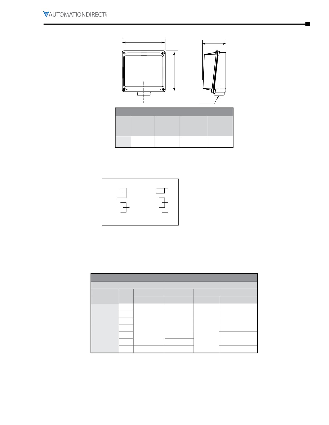
Chapter 6: Legacy Motors
MTR Junction Box Dimensions
XD
HH
XC
AA
Junction Box Dimensions (in)
AA
Frame
XD
XC
HH
(Conduit
Size
(Width)
(Height)
(Depth)
Hole)
(NPT)
56(H)
3.2
3.7
1.6
1/2
C
MTR Terminal and Wiring Diagrams
MTR General-Purpose motors
1/3 hp - 1.5hp 1Ø MTR models
6-Lead, 115/208-230 VAC
Low Voltage
High Voltage
BLUE (T1)
BLUE (T1)
LINE 1
ORANGE (T3)
LINE 1
RED (T8)
RED (T8)
WHITE (T2)
WHITE (T2)
ORANGE (T3)
INS
YELLOW (T4)
LINE 2
BLACK (T5)
BLACK (T5)
YELLOW (T4)
LINE 2
ROTATION CW-OPE TO REVERSE EITHER VOLTAGE
INTERCHANGE RED AND BLACK LEADS.
MTR Motors Decibel Levels
The decibel (sound) level of an IronHorse® motor should be measured after initial startup, after 30 days,
and after six months of use. Decibel levels should remain fairly consistent and can be an indication
of misalignment and premature bearing wear. If the measured decibel level for your IronHorse model
exceeds the value listed below by more than 10%, contact AutomationDirect or a local motor service
technician found at www.easa.com.
MTR Average T-Frame Decibel Levels
Noise Level: Lw dB(A) @ 1m
1800 RPM
3600 RPM
Frame Size
HP
1Ø
3Ø
1Ø
3Ø
1/3
1/2
75.0
3/4
65.0
65.0
56(H)C
1
-
1-1/2
80.0
2
70.0
3
-
-
-
IronHorse® General Purpose
AC Motors User Manual - 11th Ed. - 06/29/2022
Page 6-25
Chapter 6: Legacy Motors
Spare/Replacement Parts for MTR Single-Phase Motors
MTR Single-Phase Motor Spare/Replacement Parts (NOT for MTR2 Motors)*
Dimension
Applicable
Accessory
Capacitance
Rated
MTR Motor
Part Number
Height x Ø
MTR
Type
(µF)
Voltage
HP ; RPM
(in[mm])
Motor Number
MTA-CAP-01
200
MTR-P33-1AB18
1/3 ; 1800
MTR-P50-1AB18
1/2 ; 1800
MTA-CAP-02
250
MTR-P75-1AB18
3/4 ; 1800
3.15 x 1.65
Start capacitor
165
MTA-CAP-03
300
[80.0 x 41.9]
MTR-001-1AB18
1 ; 1800
MTA-CAP-04
250
MTR-1P5-1AB18
1-1/2 ; 1800
MTA-CAP-08
400
MTR-1P5-1AB36
1-1/2 ; 3600
4.02 x 1.75
MTA-CAP-06
40
MTR-1P5-1AB18
1-1/2 ; 1800
[102.1 x 44.5]
Run capacitor
450
4.0 x 1.8
MTA-CAP-09
35
MTR-1P5-1AB36
1-1/2 ; 3600
[101 x 45]
MTA-CSW-01
MTR-xxx-1AB18
all 1800 rpm
Centrifugal switch
250
MTA-CSW-02
MTR-1P5-1AB36
3600 rpm
MTAR-BASE-56
Motor base
MTAR-FAN-56
Fan
N/A
N/A
MTAR-JBOX-56
Junction box
N/A
MTR-xxx-1ABxx
All
MTAR-
Fan shroud
SHROUD-56
* These accessories are spare/replacement components only for MTR series IronHorse motors.
Accessories for MTR series motors are NOT compatible with MTR2 series motors.
MTR Series Three-Phase Motor Spare/Replacement Parts*
Part
Applicable MTR
MTR Motor
Description
Number
Motor Number
HP : RPM
MTAR-BASE-56
Motor base
MTAR-FAN-56
Fan
MTR-xxx-xBDxx
All
MTAR-JBOX-56
Junction box
MTAR-SHROUD-56
Fan shroud
* These accessories are spare/replacement components only for MTR series
IronHorse motors.
MTR Bearing Size Information
All IronHorse® cast-iron motors use premium name-brand bearings (NSK, NTN, or SKF). Below is a bearing
size chart listing the type of bearings used in each frame size of IronHorse MTR motors. The bearing types
are also listed on the motor nameplate.
MTR Bearing Size Chart
Frame
Drive End Bearing
Opposite Drive End Bearing
Size
56(H)C
6203-ZZ or 6205
6203-ZZ
Page 6-26
Chapter 6: Legacy Motors
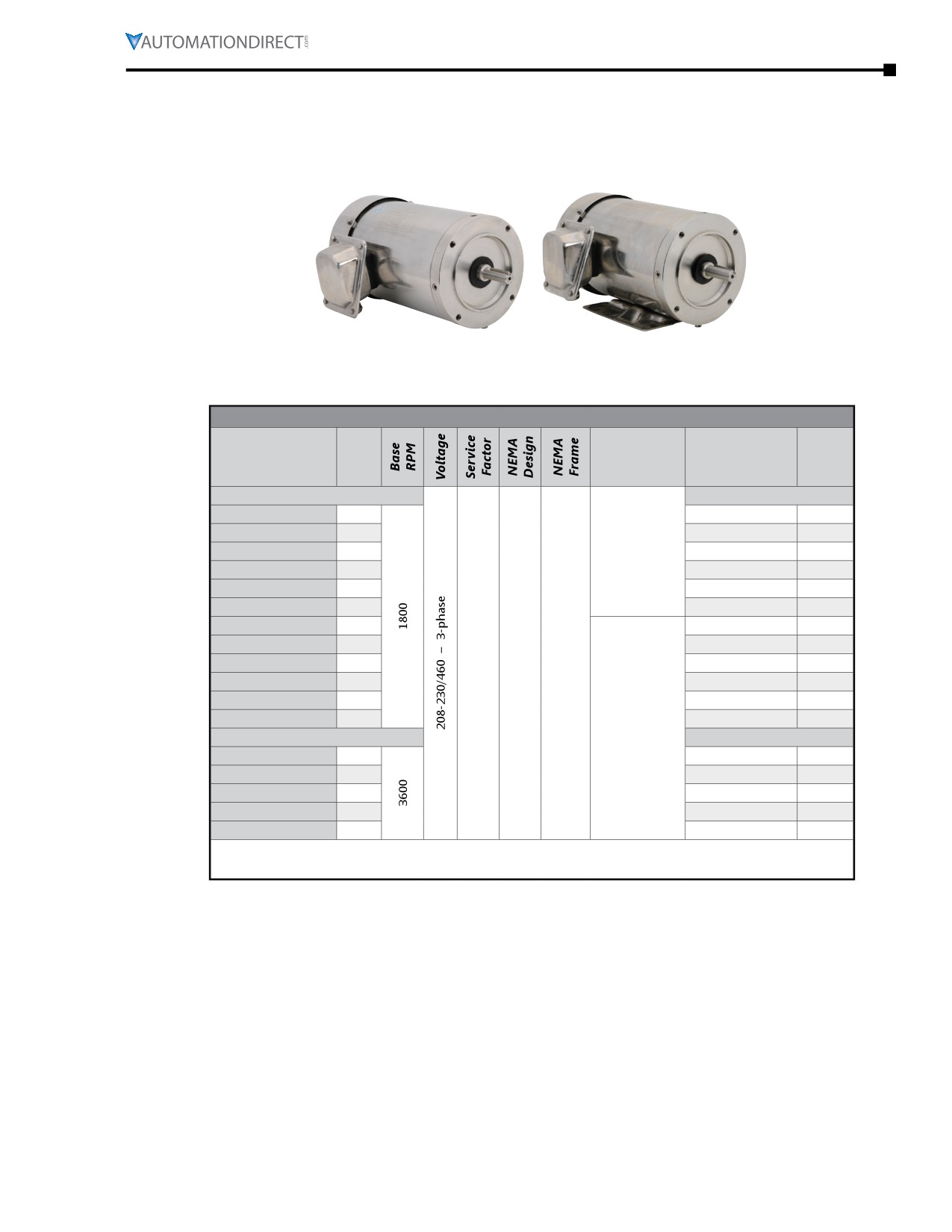
MTSS Series Motors
MTSS Features and Specifications
Stainless-Steel 56C-Frame
Stainless-Steel 56C-Frame
Three-Phase Motor with
Three-Phase Motor with
Round Body
Rigid Base
IronHorse stainless steel 56C-frame three-phase motors are available from 1/3 hp to 2 hp. All models have
TEFC frames and stainless steel end bells, and they are available with or without rigid mounting bases.
MTSS Stainless-Steel 56C-Frame 3-Phase Motor Specifications - 1800 & 3600 rpm
Motor Specifications - MTSS 3-Phase 56C-Frame Motors - 1800 & 3600 rpm
F.L. Amps
Approx
Part
HP
Housing
@
Weight
Number
208-230V/460V
(lb)
1800 RPM
1800 RPM
TEFC
MTSS-P33-3BD18R
1/3
1.5-1.4 / 0.7
27
stainless steel
MTSS-P50-3BD18R
1/2
frame with
1.55-1.5 / 0.75
27
MTSS-P75-3BD18R
3/4
round body
2.6-2.4 / 1.2
29
MTSS-001-3BD18R
1
3.5-3.2 / 1.6
34
F1 conduit box
MTSS-1P5-3BD18R
1-1/2
4.6-4.2 / 2.1
36
location
MTSS-002-3BD18R
2
6.6-6.0 / 3.0
43
MTSS-P33-3BD18
1/3
1.5-1.4 / 0.7
28
MTSS-P50-3BD18
1/2
1.55-1.5 / 0.75
28
56C
MTSS-P75-3BD18
3/4
1.15
B
flange
2.6-2.4 / 1.2
30
MTSS-001-3BD18
1
mount
TEFC
3.5-3.2 / 1.6
35
MTSS-1P5-3BD18
1-1/2
stainless steel
4.6-4.2 / 2.1
36
frame with
MTSS-002-3BD18
2
6.6-6.0 / 3.0
44
rigid base
3600 RPM
3600 RPM
MTSS-P50-3BD36
1/2
F1 conduit box
1.99-1.8 / 0.9
29
MTSS-P75-3BD36
3/4
location
2.4-2.3 / 1.15
31
MTSS-001-3BD36
1
3.3-3.0 / 1.5
31
MTSS-1P5-3BD36
1-1/2
4.2-4.0 / 2.0
36
MTSS-002-3BD36
2
5.0-4.8 / 2.4
43
Note: Please review the AutomationDirect Terms & Conditions for warranty and service on
this product.
IronHorse® General PurposeAC Motors User Manual - 11th Ed. - 06/29/2022
Page 6-27
Chapter 6: Legacy Motors
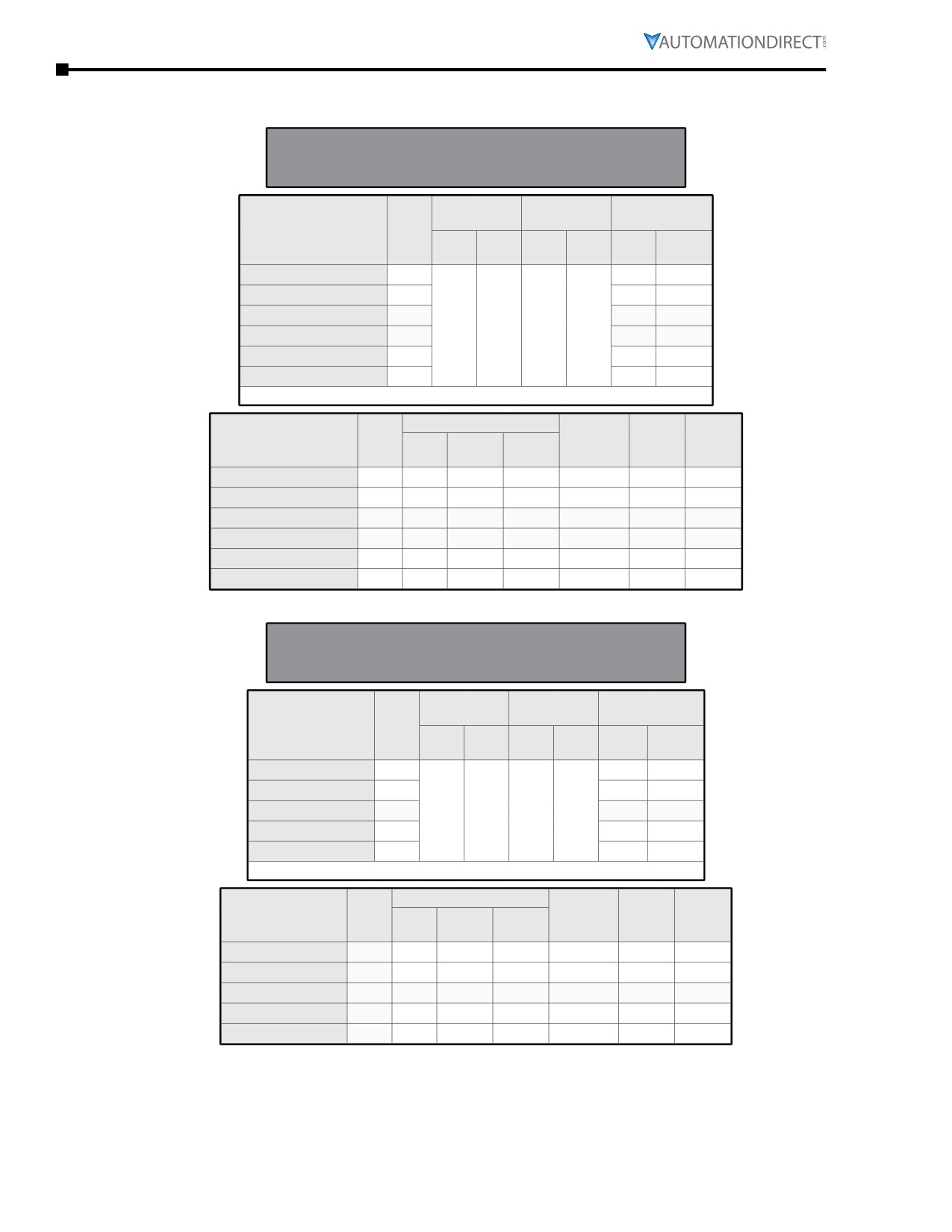
MTSS Stainless-Steel 56C-Frame 3-Phase Motors Features & Specs (continued)
MTSS Motor Performance Data - 1800 rpm
Performance Data
MTSS Three-Phase 56C-Frame Motors - 1800 rpm
(460V data except as indicated)
Minimum
Maximum
Current @
F.L.
Speed (rpm)
Speed (rpm)
460V (Amps)
Part Number
RPM
CT
VT
No
Locked
CHP*
Safe
(2:1)
(5:1)
Load
Rotor
MTSS-P33-3BD18(R)
1725
0.29
4.2
MTSS-P50-3BD18(R)
1725
0.30
4.6
MTSS-P75-3BD18(R)
1725
0.44
7.3
900
360
2250
4500
MTSS-001-3BD18(R)
1740
0.61
10.0
MTSS-1P5-3BD18(R)
1740
0.70
13.8
MTSS-002-3BD18(R)
1740
1.08
21.0
* Maximum Constant HP rpm is for direct-coupled loads.
Torque (lb·ft)
F.L.
F.L.
Rotor
Part Number
HP
Full
Locked
Break
Efficiency
Power
Inertia
Load
Rotor
-down
(%)
Factor
(lb·ft2)
MTSS-P33-3BD18(R)
1/3
1.0
2.9
3.9
82.5
0.71
0.078
MTSS-P50-3BD18(R)
1/2
1.5
3.8
5.2
82.5
0.76
0.078
MTSS-P75-3BD18(R)
3/4
2.2
5.0
7.0
82.5
0.78
0.081
MTSS-001-3BD18(R)
1
3.0
7.2
9.9
84.0
0.78
0.090
MTSS-1P5-3BD18(R)
1-1/2
4.4
10.3
14.5
84.0
0.83
0.087
MTSS-002-3BD18(R)
2
5.9
13.9
18.9
84.0
0.83
0.101
MTSS Motor Performance Data - 3600 rpm
Performance Data
MTSS Three-Phase 56C-Frame Motors - 3600 rpm
(460V data except as indicated)
Minimum
Maximum
Current @
F.L.
Speed (rpm)
Speed (rpm)
460V (Amps)
Part Number
RPM
CT
VT
No
Locked
CHP*
Safe
(2:1)
(5:1)
Load
Rotor
MTSS-P50-3BD36
3460
0.36
6.0
MTSS-P75-3BD36
3470
0.43
7.6
MTSS-001-3BD36
3470
1800
720
4500
4500
0.58
10.0
MTSS-1P5-3BD36
3480
0.70
15.0
MTSS-002-3BD36
3480
0.85
18.0
* Maximum Constant HP rpm is for direct-coupled loads.
Torque (lb·ft)
F.L.
F.L.
Rotor
Part Number
HP
Full
Locked
Break
Efficiency
Power
Inertia
Load
Rotor
-down
(%)
Factor
(lb·ft2)
MTSS-P50-3BD36
1/2
0.7
1.9
2.5
77.0
0.88
0.077
MTSS-P75-3BD36
3/4
1.1
2.7
3.3
73.0
0.84
0.100
MTSS-001-3BD36
1
1.5
4.6
5.5
80.0
0.72
0.094
MTSS-1P5-3BD36
1-1/2
2.3
6.6
9.0
84.0
0.74
0.098
MTSS-002-3BD36
2
2.9
8.6
11.3
80.0
0.72
0.107
Page 6-28
Chapter 6: Legacy Motors
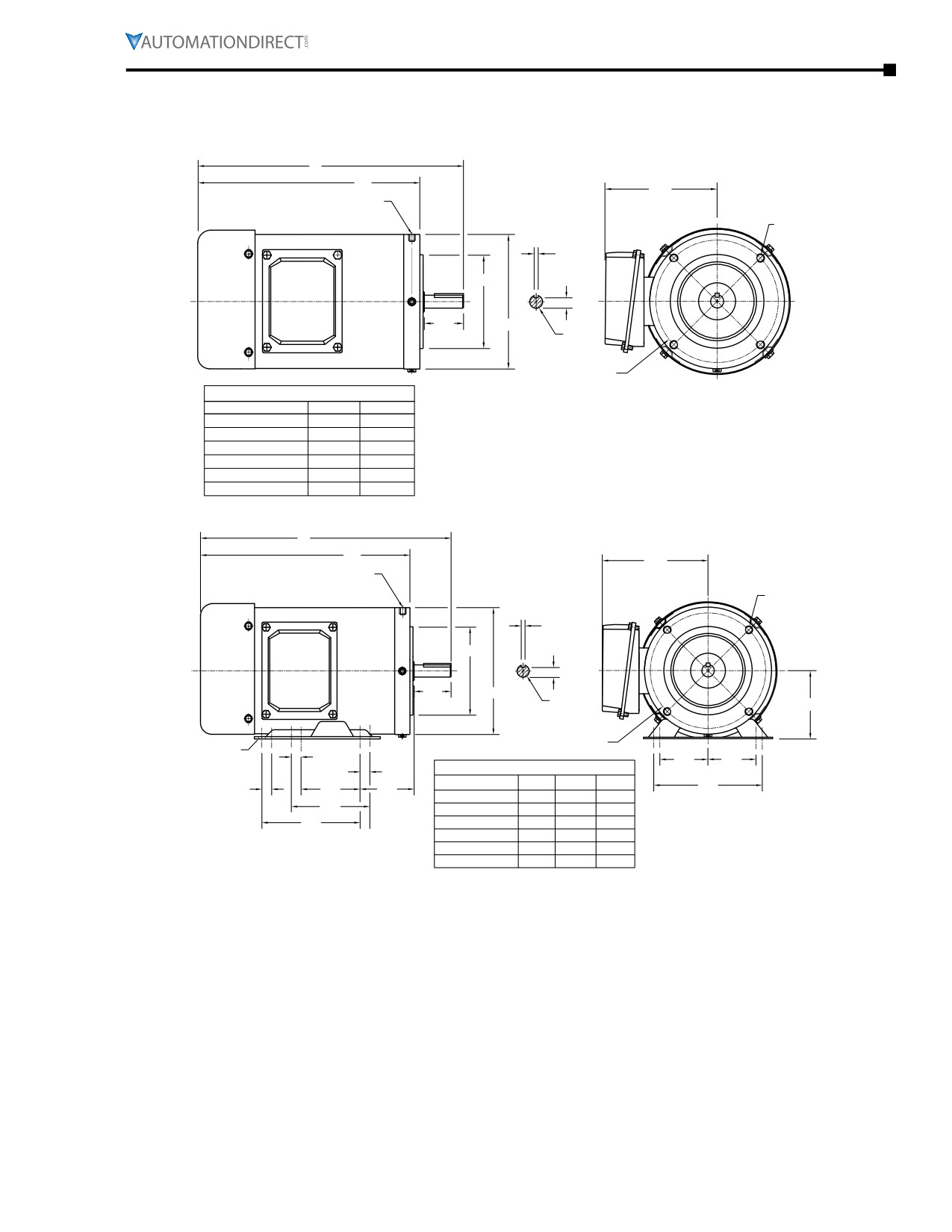
MTSS Motor Dimensions
(Dimensions = inches)
MTSS 56C-Frame Three-phase Round-body Motor Dimensions
C
AG
5.39
R1/8 BSPT THREADED DRAIN HOLE
4X FRONT, 4X REAR, 90° APART
4X 3/8-16
0.19
Ø4.50
0.52
1.88
Ø6.46
Ø0.62
Ø5.87
B.C.
AC MOTOR WITHOUT FEET
PART NUMBER
DIM. C
DIM. AG
MTSS-P33-3BD18R
11.59
9.50
MTSS-P50-3BD18R
11.59
9.50
MTSS-P75-3BD18R
12.76
10.67
MTSS-001-3BD18R
12.76
10.67
MTSS-1P5-3BD18R
12.76
10.67
MTSS-002-3BD18R
12.76
10.48
MTSS 56C-Frame Three-phase Rigid-base Motor Dimensions
C
AG
5.39
R1/8 BSPT THREADED DRAIN HOLE
4X FRONT, 4X REAR, 90° APART
4X 3/8-16
0.19
Ø4.50
0.52
1.88
Ø6.46
Ø0.62
3.50
Ø5.87
Ø0.34 SLOT
B.C.
0.50
2.44
2.44
0.50
AC MOTOR WITH FEET
PART NUMBER
DIM. C
DIM. AG
DIM. F3
5.50
0.50
3.00
2.75
MTSS-P33-3BD18
11.77
9.69
n/a
4.00
MTSS-P50-3BDxx
11.77
9.69
n/a
F3
MTSS-P75-3BDxx
12.76
10.67
5.00
MTSS-001-3BDxx
12.76
10.67
5.00
MTSS-1P5-3BDxx
12.76
10.67
5.00
MTSS-002-3BDxx
13.50
11.42
5.00
IronHorse® General Purpose
AC Motors User Manual - 11th Ed. - 06/29/2022
Page 6-29
Chapter 6: Legacy Motors
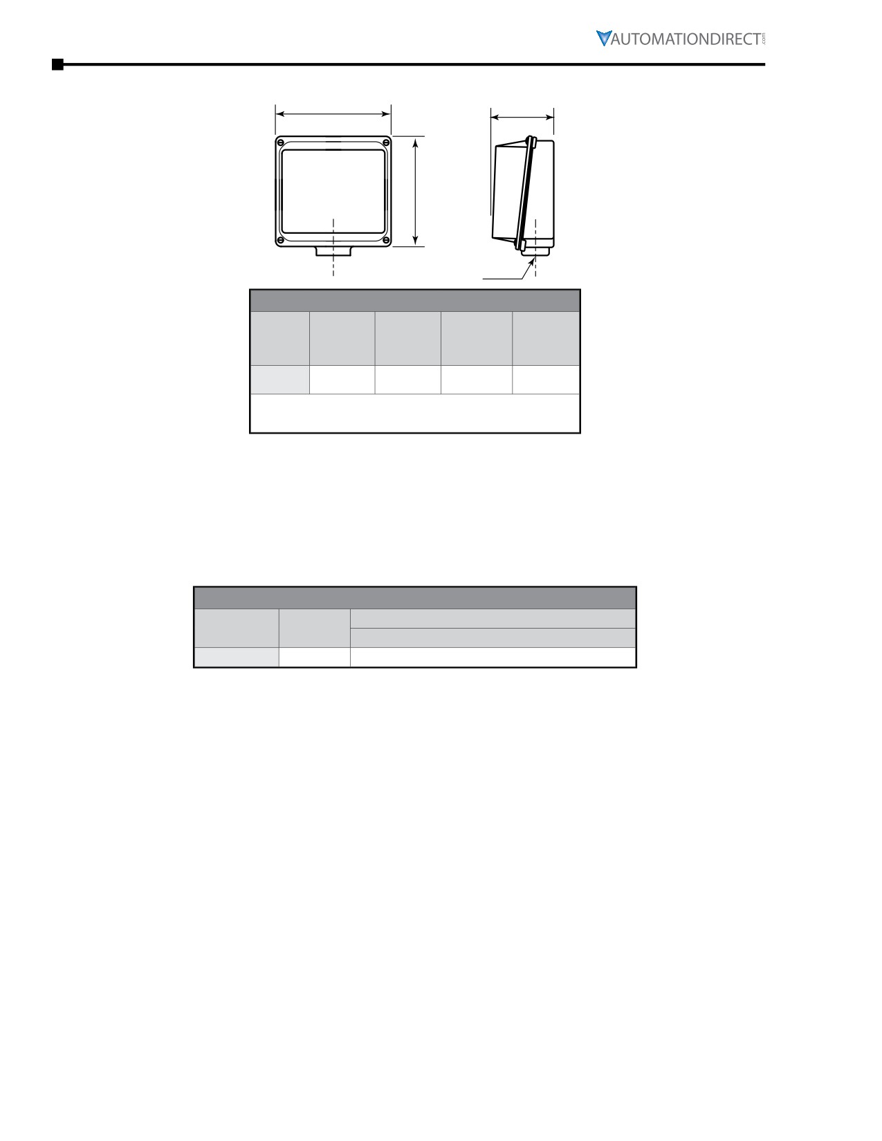
MTSS Junction Box Dimensions
XD
HH
XC
AA
Junction Box Dimensions (in)
AA
Frame
XD
XC
HH
(Conduit
Size *
(Width)
(Height)
(Depth)
Hole)
(NPT)
56
3.8
3.3
1.5
0.86*
* MTSS conduit holes are unthreaded through
holes with cable glands installed.
MTSS Decibel Levels
The decibel (sound) level of an IronHorse® motor should be measured after initial startup, after 30 days,
and after six months of use. Decibel levels should remain fairly consistent and can be an indication
of misalignment and premature bearing wear. If the measured decibel level for your IronHorse model
exceeds the value listed below by more than 10%, contact AutomationDirect or a local motor service
technician found at www.easa.com.
MTSS Average T-Frame Decibel Levels
Noise Level: Lw dB(A) @ 1m
Frame Size
HP
MTSS
56C
-
65
Page 6-30
Chapter 6: Legacy Motors
MTSS Motor Mounting
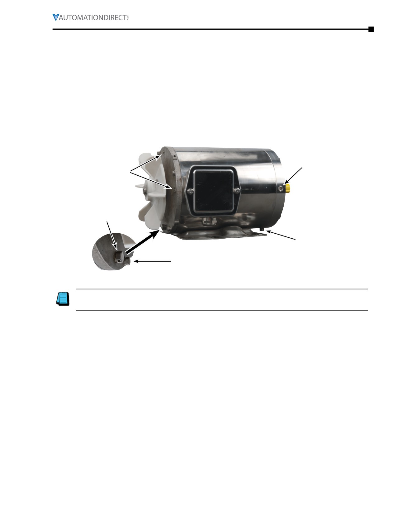
MTSS stainless-steel motors can be mounted in any orientation, horizontal or vertical, as long as the
drain plugs are installed in the two lower locations.
The motors have four drain holes in the 12:00, 3:00, 6:00, and 9:00 positions of each end of the motor. The
motors are shipped with two drain plugs installed in the front and rear 6:00 positions of the end bells,
and drain-hole seal plugs installed in the other positions. This is the standard arrangement for the most
‘normal’ horizontal mounting orientation for a rigid-base motor.
When the motors are mounted in other orientations, switch drain plugs and seals so that there are two
drain plugs on opposite sides of the bottom surface of the motor. For example, in a shaft-downward
mounting orientation, install both drain plugs 180° apart in the front end bell. (Remove the fan shroud for
access to the rear drain plugs and seals.)
Motor shown with fan cover removed
front drain-hole
rear drain-hole
seal plugs (3)
seal plugs (3)
rear drain plug
(standard position)
front drain plug
(standard position)
through bolt
Some IronHorse motors include a shaft slinger (rubber washer) on the output shaft at the end bell. The shaft
slinger provides an added layer of protection to the output shaft seal. We recommend leaving the slinger in
place, but it can be removed if it poses an interference problem with C-Face-mounted gearboxes.
IronHorse® General PurposeAC Motors User Manual - 11th Ed. - 06/29/2022
Page 6-31
Chapter 6: Legacy Motors
Spare/Replacement Parts for MTSS Stainless-Steel Three-Phase Motors
MTSS Stainless-Steel Three-Phase Motor Replacement Parts
Part Number
Description
Picture
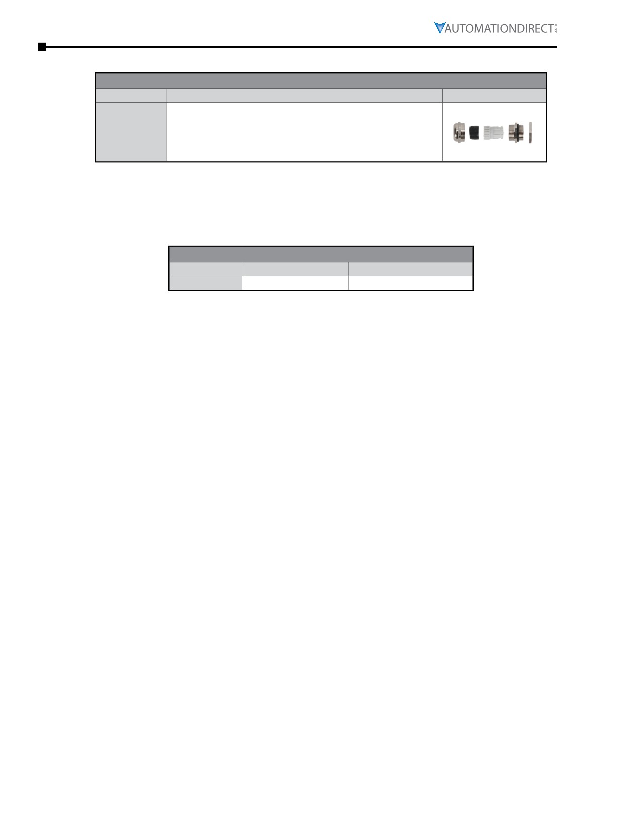
Cable gland; M22 x 1.5 mm thread; (1) silicone rubber gasket
accommodates a cable diameter range of 0.393 to 0.512 in (10 to 13
MTAS-CG-M22
mm); IP66 protection level; nickel-plated brass housing.
This is a SPARE part for IronHorse MTSS motors - one cable gland is
pre-installed on each MTSS motor.
MTSS Bearing Size Information
All IronHorse® cast-iron motors use premium name-brand bearings (NSK, NTN, or SKF). Below is a bearing
size chart listing the type of bearings used in each frame size of IronHorse MTSS motors. The bearing types
are also listed on the motor nameplate.
MTSS Bearing Size Chart
Frame Size
Drive End Bearing
Opposite Drive End Bearing
56C
6203-ZZ or 6205
6205
Page 6-32
Chapter 6: Legacy Motors
MTC EPAct Series Motors
MTC Features and Specifications
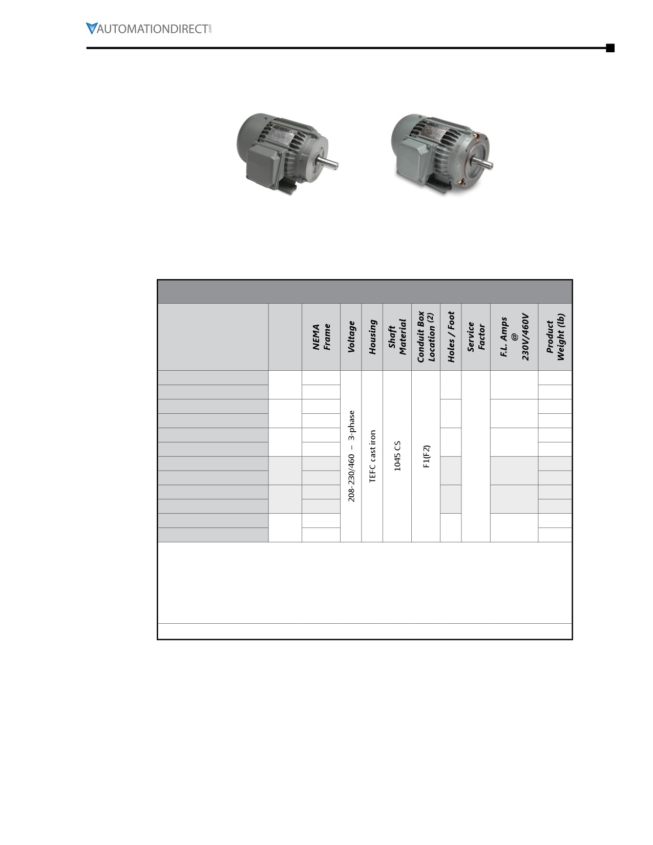
EPAct Cast-Iron T-Frame
EPAct Cast-Iron TC-Frame
IronHorse 1800 rpm T-frame cast-iron industrial duty EPAct motors are available from 1-300 hp, and
TC-frame motors are available from 1-100 hp. Optional C-face kits are available for IronHorse T-frame
EPAct motors. (EPAct C-face kits are NOT compatible with Premium Efficiency motors.) All models have a
TEFC frame and full length mounting feet.
MTC Motor Specifications - Cast-Iron T-frame and TC-frame - 1800 rpm
Motor Specifications - EPAct T & TC(1) Frame Three-Phase Motors - 1800 rpm
Part Number
HP(3)
MTC-001-3BD18
143T
58
1
2
3.0 / 1.5
MTC-001-3BD18CK (1)
143TC
61
MTC-1P5-3BD18
145T
60
1-1/2
3
4.2 / 2.1
MTC-1P5-3BD18CK (1)
145TC
67
MTC-002-3BD18
145T
70
2
3
5.4 / 2.7
MTC-002-3BD18CK (1)
145TC
69
1.15
MTC-003-3BD18
182T
90
3
2
7.72 / 3.86
MTC-003-3BD18CK (1)
182TC
112
MTC-005-3BD18
184T
110
5
3
11.8 / 5.9
MTC-005-3BD18CK (1)
184TC
125
MTC-7P5-3BD18
213T
160
7-1/2
2
18.6 / 9.3
MTC-7P5-3BD18CK (1)
213TC
170
1) TC-frame motors are T-frame motors with applicable C-face accessory kits installed.
2) F1(F2) indicates F1 conduit box mounting location, field convertible to F2.
(Refer to “Chapter 5: Reference” for further information regarding F1 and F2
mounting.)
3) For warranty on motors 50 hp and above, motors must be inspected by an EASA
motor repair or service center. See AutomationDirect Terms & Conditions for details.
*** TABLE CONTINUED ON NEXT PAGE ***
IronHorse® General PurposeAC Motors User Manual - 11th Ed. - 06/29/2022
Page 6-33