Q2V Driving Quality. Technical Manual (Item code: Q2V-Axxxx-xxx, 2020) - page 19
12.10 o: KEYPAD
1 : Coast->Stop
2 : Fast Stop (C1-09)
3 : Alarm Only
4 : No Alarm Display
◆ o3: COPY FUNCTION
o3 parameters set the operation of the parameter backup function.
■ o3-01: COPY Keypad Selection of Mode
No.
Default
Name
Description
(Hex.)
(Range)
COPY Keypad Selection of
V/f
OLV OLV/PM AOLV/PM EZOLV
o3-01
0
Mode
(0515)
Sets the function that saves and copies drive parameters to a different drive with the keypad.
(0 - 4)
0 : Copy Select
1 : Bck (Drive->OPE)
The parameter setting values are read from the drive and saved in the keypad.
2 : Res (OPE->Drive)
Copies the parameter setting values saved in the keypad to a different drive.
3 : Verify (Check)
Makes sure that the parameter setting values in the drive agree with the parameters saved in the keypad.
4 : Del (Clear OPE Memory)
Deletes the parameter setting values saved in the keypad.
■ o3-02: COPY Allow Selection
No.
Default
Name
Description
(Hex.)
(Range)
COPY Allow Selection
V/f
OLV OLV/PM AOLV/PM EZOLV
o3-02
0
(0516)
Sets the copy function when o3-01 = 1 [COPY Keypad Selection of Mode = Bck (Drive->OPE)].
(0, 1)
Note:
When you select [Parameter Backup] on the keypad menu screen to do the backup function, the drive automatically sets o3-02 =
1.
0 : Disabled
1 : Enabled
■ o3-04: COPY Memory Selection
No.
Default
Name
Description
(Hex.)
(Range)
COPY Memory Selection
V/f
OLV OLV/PM AOLV/PM EZOLV
o3-04
0
(0B3E)
Sets the storage location for drive parameters when you back up and restore parameters. This
(0 - 3)
parameter is only available when using an LCD keypad.
You can use the LCD keypad to make a maximum of 4 parameter backup sets.
0 : Memory 1
1 : Memory 2
2 : Memory 3
3 : Memory 4
■ o3-05: COPY Items Selection
No.
Default
Name
Description
(Hex.)
(Range)
COPY Items Selection
V/f
OLV OLV/PM AOLV/PM EZOLV
o3-05
0
(0BDA)
Sets which parameters are backed up, restored, and referenced. This parameter is only available
(0, 1)
when using an LCD keypad.
0 : Std
1 : Std+Solution
706
12.10 o: KEYPAD
Note:
• Parameters [q: Q2PACK PARAMETERS] and rx-xx [r: Q2PACK JOINTS] show when A1-07 = 1 or 2 [Q2pack Enable = Enable
Q2pack or With DI].
• The password for Q2pack PC software is necessary to back up qx-xx and rx-xx. If you enter an incorrect password, the drive detects
PWEr [Q2pack Password Mismatch].
■ o3-06: AutoBackup Selection
No.
Default
Name
Description
(Hex.)
(Range)
AutoBackup Selection
V/f
OLV OLV/PM AOLV/PM EZOLV
o3-06
1
(0BDE)
Sets the function that automatically backs up parameters. This parameter is only available when
(0, 1)
using an LCD keypad.
When you connect the drive and keypad, parameters set to the drive are automatically backed up to the keypad as
specified by the setting of parameters o3-06 and o3-07.
0 : Disabled
1 : Enabled
Note:
When you replace the LCD keypad then energize the drive, the keypad shows the restore operation screen automatically to restore the
drive configuration with the parameters backed up to the LCD keypad. If you connect an LCD keypad that does not have parameter
backup data, the keypad will not show the restore operation screen.
■ o3-07: AutoBackup Lapse
No.
Default
Name
Description
(Hex.)
(Range)
AutoBackup Lapse
V/f
OLV OLV/PM AOLV/PM EZOLV
o3-07
2
(0BDF)
Sets the interval at which the automatic parameter backup function saves parameters from the
(1 - 4)
drive to the keypad.
The drive saves parameter settings to the keypad at these times:
1. After you energize the drive and the auto backup period passes.
2. When you use ROM enter or the keypad to change parameters, the drive saves those changes in the drive,
waits for the auto backup period to pass, then saves those parameters in the keypad.
Note:
The drive can write data to the keypad a maximum of 100,000 times. If you write data to the keypad more than 100,000 times, you must
replace the keypad.
1 : 10 minutes
2 : 30 minutes
3 : 60 minutes
4 : 12 hours
◆ o4: MAINTENANCE MONITORS
o4 parameters set the expected service life to help you know when to replace parts. The drive will show an alarm
to tell you when the replacement part interval is near.
■ o4-01: Cum.Oper TimeSetting
No.
Default
Name
Description
(Hex.)
(Range)
Cum.Oper TimeSetting
V/f
OLV OLV/PM AOLV/PM EZOLV
o4-01
0h
(050B)
Sets the initial value of the cumulative drive operation time in 10-hour units.
(0 - 9999 h)
When you select o4-01 on the keypad, it will show the current value of U4-01 in units of 10 hours (h). When you
change the setting of o4-01 through the monitor, the U4-01 count starts again as specified by the setting of o4-01.
Note:
Set this parameter in 10-hour (h) units. When o4-01 = 30, U4-01 [Cumulative OpeTime] = 300 h.
12
707
12.10 o: KEYPAD
■ o4-02: Cum.Oper TimeSelect
No.
Default
Name
Description
(Hex.)
(Range)
Cum.Oper TimeSelect
V/f
OLV OLV/PM AOLV/PM EZOLV
o4-02
1
(050C)
Sets the condition that counts the cumulative operation time.
(1, 2)
1 : Log Power-On Time
Counts the time from when the drive is energized to when it is de-energized.
2 : Log Run Time
Counts the time that the drive outputs voltage.
■ o4-03: Fan.Oper Setting
No.
Default
Name
Description
(Hex.)
(Range)
Fan.Oper Setting
V/f
OLV OLV/PM AOLV/PM EZOLV
o4-03
0h
(050E)
Sets the value from which to start the cumulative drive cooling fan operation time in 10-hour
(0 - 9999 h)
units.
Use monitor U4-03 [Fan Oper.Time] to view the total operation time of the cooling fan. When you replace a
cooling fan, set o4-03 = 0 to reset U4-03. Select o4-03 on the keypad to show the current value of U4-03 in 10-
hour (h) units. If you use the monitor to change o4-03, the recount of U4-03 starts with the o4-03 setting.
The drive sets o4-03 in 10-hour (h) units. When o4-03 = 30, U4-03 [Fan Oper.Time] will show “300 h”.
■ o4-05: Cap.Maint.Setting
No.
Default
Name
Description
(Hex.)
(Range)
Cap.Maint.Setting
V/f
OLV OLV/PM AOLV/PM EZOLV
o4-05
0%
(051D)
Sets the U4-05 [Capacitor Maintenance] monitor value.
(0 - 150%)
When you replace a drive, set o4-05 = 0 to reset U4-05. When the o4-05 setting changes, the count of U4-05
starts again as specified by the setting of o4-05. After you complete the configuration, o4-05 automatically resets
to 0.
Note:
The maintenance period changes for different operating environments.
■ o4-07: PreChgRly Preset Maintenance Cnt
No.
Default
Name
Description
(Hex.)
(Range)
PreChgRly Preset
V/f
OLV OLV/PM AOLV/PM EZOLV
o4-07
0%
Maintenance Cnt
(0523)
Sets the U4-06 [SoftChgRelay Maint] monitor value.
(0 - 150%)
When you replace a drive, set o4-07 = 0 to reset U4-06. When the o4-07 setting changes, the count of U4-06
starts again as specified by the setting of o4-07. After you complete the configuration, o4-07 automatically resets
to 0.
Note:
The maintenance period changes for different operating environments.
■ o4-09: IGBT Preset Maintenance Cnt
No.
Default
Name
Description
(Hex.)
(Range)
IGBT Preset Maintenance
V/f
OLV OLV/PM AOLV/PM EZOLV
o4-09
0%
Cnt
(0525)
Sets the U4-07 [IGBT Maintenance] monitor value.
(0 - 150%)
When you replace a drive, set o4-09 = 0 to reset U4-07. When the o4-09 setting changes, the count of U4-07
starts again as specified by the setting of o4-09. After you complete the configuration, o4-09 automatically resets
to 0.
Note:
The maintenance period changes for different operating environments.
708
12.10 o: KEYPAD
■ o4-11: Flt.History Initialization
No.
Default
Name
Description
(Hex.)
(Range)
Flt.History Initialization
V/f
OLV OLV/PM AOLV/PM EZOLV
o4-11
0
(0510)
Resets the records of Monitors U2: FAULT and U3: FAULT HISTORY.
(0, 1)
Note:
When you initialize the drive with A1-03 [Init Parameters], the drive will not reset the records for U2-xx and U3-xx.
0 : No Reset
Keeps the records of Monitors U2-xx and U3-xx.
1 : Reset
Resets the records for Monitors U2-xx and U3-xx. After the reset, the drive automatically resets o4-11 to 0.
■ o4-12: kWh Monitor Initialization
No.
Default
Name
Description
(Hex.)
(Range)
kWh Monitor Initialization
V/f
OLV OLV/PM AOLV/PM EZOLV
o4-12
0
(0512)
Resets the monitor values for U4-10 [kWh Lower 4Digits] and U4-11 [kWh Upper 5Digits].
(0, 1)
Note:
When you initialize the drive with A1-03 [Init Parameters], the drive will not reset U4-10 and U4-11.
0 : No Reset
Keeps the monitor values for U4-10 and U4-11.
1 : Reset
Resets the values of U4-10 and U4-11. After the reset, the drive automatically resets o4-12 to 0.
■ o4-13: NumOfRunCom Init Counter
No.
Default
Name
Description
(Hex.)
(Range)
NumOfRunCom Init
V/f
OLV OLV/PM AOLV/PM EZOLV
o4-13
0
Counter
(0528)
Resets the monitor values for U4-02 [Num of Run Commands], U4-24 [No of Travels(L)], and
(0, 1)
U4-25 [No of Travels(H)].
0 : No Reset
Keeps the monitor values for U4-02, U4-24, and U4-25.
1 : Reset
Resets the values of U4-02, U4-24, and U4-25. After the reset, the drive automatically resets o4-13 to 0.
■ o4-22: Time Format
No.
Default
Name
Description
(Hex.)
(Range)
Time Format
V/f
OLV OLV/PM AOLV/PM EZOLV
o4-22
0
(154F)
Sets the time display format. This parameter is only available when using an LCD keypad.
(0 - 2)
RUN
Sets the display of the time shown in the upper-left of the LCD keypad screen.
0 : 24 Hour Clock
1 : 12 Hour Clock
2 : 12 Hour JP Clock
■ o4-23: Date Format
No.
Default
Name
Description
(Hex.)
(Range)
Date Format
V/f
OLV OLV/PM AOLV/PM EZOLV
o4-23
0
(1550)
Sets the date display format. This parameter is only available when using an LCD keypad.
(0 - 2)
RUN
12
Sets the date format that the drive uses for the fault history and other records.
709
12.10 o: KEYPAD
0 : YYYY/MM/DD
1 : DD/MM/YYYY
2 : MM/DD/YYYY
■ o4-24: bAT Detection Selection
No.
Default
Name
Description
(Hex.)
(Range)
bAT Detection Selection
V/f
OLV OLV/PM AOLV/PM EZOLV
o4-24
0
(310F)
Sets the operation when the drive detects bAT [Keypad Battery Low Voltage] and TiM [Keypad
(0 - 2)
Time Not Set]. This parameter is only available when you use an LCD keypad.
RUN
0 : Disabled
The drive will not detect bAT or TiM.
1 : Enable (Alarm Detected)
The keypad shows bAT or TiM and the drive continues operation. The output terminal set to Alarm [H2-01 to H2-
03 = 4] activates.
2 : Enable (Fault Detected)
The output turns off and the motor coasts to stop. The output terminal set for Fault [H2-01 to H2-03 = 3]
activates.
◆ o5: DATA LOGGER
The data log function saves drive status information as a CSV file in the micro SD memory card in the keypad.
Monitors Ux-xx are the source of data log information. You can record a maximum of 10 monitors.
Change the LCD keypad screen from the main menu to the Diagnostic Tools screen and select the data log
function. Set the number of the monitor to record and the sampling time, then start to record the data log.
Table 12.57 Setting Parameters for Data Log Items
No.
Name
Default
Data Log Monitors
o5-03
Log Mon Data 1
101
U1-01 [Frequency Reference]
o5-04
Log Mon Data 2
102
U1-02 [Output Frequency]
o5-05
Log Mon Data 3
103
U1-03 [Output Current]
o5-06
Log Mon Data 4
107
U1-07 [DC Bus Voltage]
o5-07
Log Mon Data 5
108
U1-08 [Output Power]
o5-08
Log Mon Data 6
000
Not selected
o5-09
Log Mon Data 7
000
Not selected
o5-10
Log Mon Data 8
000
Not selected
o5-11
Log Mon Data 9
000
Not selected
o5-12
Log Mon Data 10
000
Not selected
Note:
• Failure to obey can cause the log function to fail after you restore power or connect the keypad. Do not de-energize the drive or
disconnect the keypad from the drive during log transfer communication.
• You can use a Micro SDHC card a maximum of 32 GB capacity.
■ Log File Specifications
Item
Specification
File storage location
A folder called [Log_File] is created in the root directory of the micro SD card.
Filename
GLOG0xxx.csv
Note:
[xxx] identifies a 3-digit decimal number
Maximum number of files
999
(GLOG0001.csv to GLOG0999.csv)
Character code
ASCII code
Line break code
<CR><LF>
710
12.10 o: KEYPAD
Item
Specification
Separating character
[ , ] (Commas)
Header Rows
First Row: Drive information including Drive Model, software version, control method, and sampling time
Second Row: Log data information including the monitor number, number decimal points, and unit code
■ Log File Configuration
The [Log_Files] folder is created in the root directory of the micro SD card. This is where the log data is stored as
CSV files. Log data files are created in this configuration. The number of rows changes when the number of
selected monitors change.
First Row
Drive information
Second Row
Log data information
Third Row
Log data 1
:
Log data 2
:
Log data 3
:
:
Last Row
Log data n
First Row: Drive Information
This example shows the data text strings and data generated for the first row of log data.
Example of generated data: 00,0012,160107111230,Q2V,VSVA22010,2,62,1000,000001
Number
of
No.
Item
Example
Description
Charac
ters
1
Attribute
2
00
[00] shows that the record is a drive information record.
2
File number
4
0012
Generates the [xxx] part (a 3-digit decimal number) of the [GLOG0xxx.csv] filename of the log data
in hexadecimal format.
Example filename of [GLOG0018.csv]: 018 (Dec.) = 0012 (Hex.)
3
Time stamp *1
12
160107111230
Date file was generated
・Date: 20YY/MM/DD
・Time in 24-hour format: HH:MM:SS
Example data of [160107111230]: 11:12:30 on January 7, 2016
4
Model
3
Q2V
Drive model information
5
Software number
9
VSVA22010
Drive software number
6
Control method selection
1
2
Setting value (Hex.) of A1-02 [Control Method]
7
Drive capacity
2
62
Setting value (Hex.) of o2-04 [Drive KVA Selection]
8
Sampling time
5
1000
Setting value (Dec.) of o5-02 [Log Sample Lapse]
(maximum)
Unit: ms
9
Row number
6
000001
Row number (Hex.) in the data log file
*1
If you do not set the time in the keypad, the text string of [000000000000] is generated to show the time.
Second Row: Log Data Information
This example shows the data text strings and data generated for the second row of log data.
Example of generated data:
01,0012,160107111230,0101,0201,0102,0201,0103,0206,0107,0005,0108,0209,0000,0000,0000,0000,0000,0
000,0000,0000,0000,0000,0000,0000,0000,0000,000002
Number of
No.
Item
Description
Characters
1
Attribute
2
[01] shows that the record is a log data information record.
2
File number
4
Generates the [xxx] part (a 3-digit decimal number) of the [GLOG0xxx.csv] filename of the log data in hexadecimal
format.
3
Time stamp
12
Date file was generated
4
Monitor Number 1 *1
4
Monitor number selected by o5-03 [Log Mon Data 1]
Ex.: 0101 (Dec.) for U1-01
12
711
12.10 o: KEYPAD
Number of
No.
Item
Description
Characters
5
Monitor Unit 1 *2
4
Unit code and number of decimal places used for the monitor selected with o5-03
Example when U1-01 = 30.00 Hz:
Number of decimal places = 2, Hz unit code = 01, monitor unit 1 = 0201 (Hex.)
6
Monitor number 2
4
Monitor number (Dec.) selected by o5-04 [Log Mon Data 2]
7
Monitor Unit 2
4
Unit code and number of decimal places used for the monitor selected with o5-04
:
:
:
:
22
Monitor number 10
4
Monitor number (Dec.) selected by o5-12 [Log Mon Data 10]
23
Monitor Unit 10
4
Unit code and number of decimal places used for the monitor selected with o5-12
24 - 27
Reserved
4
-
28
Row number
6
Row number (Hex.) in the data log file
*1
If there is no data log monitor selected, the text string of [0000] is generated.
*2
Refer to Table 12.58 for information about unit codes.
Table 12.58 Unit Codes
Unit Code (Hex.)
Unit
Unit Code (Hex.)
Unit
Unit Code (Hex.)
Unit
Unit Code (Hex.)
Unit
00
-
08
PPR
10
H
18
0H
01
Hz
09
kW
11
V
19
-
02
RPM
0A
Ω
12
us
1A
-
03
%
0B
ms
13
min
1B
-
04
VAC
0C
kHz
14
°C
1C
-
05
VDC
0D
PSI
15
W
1D
-
06
A
0E
MPM
16
kWH
1E
-
07
sec
0F
FPM
17
MWH
1F
-
Third and Subsequent Rows: Log Data
This example shows the data text strings and data generated for the third row of log data.
Example of generated data:
02,0012,160107111239,1770,1770,00BE,0118,0028,0000,0000,0000,0000,0000,0000,0000,00000C
Number of
No.
Item
Description
Characters
1
Attribute
2
[02] shows that the record is a monitor data record.
2
File number
4
Generates the [xxx] part (a 3-digit decimal number) of the [GLOG0xxx.csv] filename of the log data in hexadecimal
format.
3
Time stamp
12
Data log data was retrieved (YYMMDDHHMMSS)
4
Log Monitor Data 1
4
Log monitor data (Hex.) of the monitor selected with o5-03 [Log Mon Data 1]
5
Log Monitor Data 2
4
Log monitor data (Hex.) of the monitor selected with o5-04 [Log Mon Data 2]
:
:
:
:
13
Log Monitor Data 10
4
Log monitor data (Hex.) of the monitor selected with o5-12 [Log Mon Data 10]
14
Reserved
4
-
15
Encoding data
4
Log Monitor Data 1 to 10 Code Data (Hex.)
Bits 0 through 9 show the encoding of log monitor data 1 1 through 10. A bit value of 1 shows that the data represents
a negative value. (Log monitor data 1 through 10 is absolute value data without encoding)
Example when log monitor data 2, 5, and 8 show negative values: Bits 1, 4, and 7 have values of 1, and the encoding
data = 0010010010 (Bin.) = 0092 (Hex.)
16
Row number
6
Row number (Hex.) in the data log file
■ o5-01: Log Start Selection
No.
Default
Name
Description
(Hex.)
(Range)
Log Start Selection
V/f
OLV OLV/PM AOLV/PM EZOLV
o5-01
0
(1551)
Sets the data log function. This parameter is only available when using an LCD keypad.
(0 - 1)
RUN
0 : OFF
712
12.10 o: KEYPAD
Stops the data log.
1 : ON (Data Logging)
Starts the data log as specified by the sampling cycle set in o5-02 [Log Sample Lapse].
■ o5-02: Log Sample Lapse
No.
Default
Name
Description
(Hex.)
(Range)
Log Sample Lapse
V/f
OLV OLV/PM AOLV/PM EZOLV
o5-02
1000 ms
(1552)
Sets the data log sampling cycle. This parameter is only available when using an LCD keypad.
(100 - 60000 ms)
RUN
■ o5-03: Log Mon Data 1
No.
Default
Name
Description
(Hex.)
(Range)
Log Mon Data 1
V/f
OLV OLV/PM AOLV/PM EZOLV
o5-03
101
(1553)
Sets the data log monitor. This parameter is only available when using an LCD keypad.
(000, 101 - 999)
RUN
Note:
Set the number of the U monitor to record the data log.
For example, to show U1-01 [PID Feedback], set o5-03 = 101. When it is not necessary to set data log monitors, set this parameter to
000. You cannot set [U2: FAULT] or [U3: FAULT HISTORY].
■ o5-04: Log Mon Data 2
No.
Default
Name
Description
(Hex.)
(Range)
Log Mon Data 2
V/f
OLV OLV/PM AOLV/PM EZOLV
o5-04
102
(1554)
Sets the data log monitor. This parameter is only available when using an LCD keypad.
(000, 101 - 999)
RUN
Note:
Set the U monitor number you will log.
For example, to show U1-02 [Output Frequency], set o5-04 = 102. When it is not necessary to set data log monitor, set this parameter to
000.
■ o5-05: Log Mon Data 3
No.
Default
Name
Description
(Hex.)
(Range)
Log Mon Data 3
V/f
OLV OLV/PM AOLV/PM EZOLV
o5-05
103
(1555)
Sets the data log monitor. This parameter is only available when using an LCD keypad.
(000, 101 - 999)
RUN
Note:
Sets the number of the U monitor you will log.
For example, to show U1-03 [Output Current], set o5-05 = 103. When it is not necessary to set data log monitors, set this parameter to
000. You cannot select [U2: FAULT] or [U3: FAULT HISTORY].
■ o5-06: Log Mon Data 4
No.
Default
Name
Description
(Hex.)
(Range)
Log Mon Data 4
V/f
OLV OLV/PM AOLV/PM EZOLV
o5-06
107
(1556)
Sets the data log monitor. This parameter is only available when using an LCD keypad.
(000, 101 - 999)
RUN
Note:
Sets the number of the U monitor you will log.
For example, to show U1-07 [DC Bus Voltage], set o5-06 = 107. When it is not necessary to set data log monitors, set this parameter to
000. You cannot select [U2: FAULT] or [U3: FAULT HISTORY].
12
713
12.10 o: KEYPAD
■ o5-07: Log Mon Data 5
No.
Default
Name
Description
(Hex.)
(Range)
Log Mon Data 5
V/f
OLV OLV/PM AOLV/PM EZOLV
o5-07
108
(1557)
Sets the data log monitor. This parameter is only available when using an LCD keypad.
(000, 101 - 999)
RUN
Note:
Sets the number of the U monitor you will log.
For example, to show U1-08 [Output Power], set o5-07 = 108. When it is not necessary to set data log monitors, set this parameter to
000. You cannot select [U2: FAULT] or [U3: FAULT HISTORY].
■ o5-08: Log Mon Data 6
No.
Default
Name
Description
(Hex.)
(Setting Range)
Log Mon Data 6
V/f
OLV OLV/PM AOLV/PM EZOLV
o5-08
000
(1558)
Sets the data log monitor. This parameter is only available when using an LCD keypad.
(000, 101 - 999)
RUN
Note:
Set the U monitor number you want to log.
For example, to display U1-01 [Frequency Reference], set o5-08 = 101. When it is not necessary to set a data log monitor, set this
parameter to 000. You cannot select [U2: FAULT] or [U3: FAULT HISTORY].
■ o5-09: Log Mon Data 7
No.
Default
Name
Description
(Hex.)
(Range)
Log Mon Data 7
V/f
OLV OLV/PM AOLV/PM EZOLV
o5-09
000
(1559)
Sets the data log monitor. This parameter is only available when using an LCD keypad.
(000, 101 - 999)
RUN
Note:
Set the U monitor number you will log.
For example, to show U1-01 [Frequency Reference], set o5-09 = 101. When it is not necessary to set data log monitor, set this
parameter to 000.
■ o5-10: Log Mon Data 8
No.
Default
Name
Description
(Hex.)
(Range)
Log Mon Data 8
V/f
OLV OLV/PM AOLV/PM EZOLV
o5-10
000
(155A)
Sets the data log monitor. This parameter is only available when using an LCD keypad.
(000, 101 - 999)
RUN
Note:
Sets the number of the U monitor you will log.
For example, to show U1-01 [Log Mon Data 8], set o5-10 = 101. When it is not necessary to set data log monitors, set this parameter to
000. You cannot select [U2: FAULT] or [U3: FAULT HISTORY].
■ o5-11: Log Mon Data 9
No.
Default
Name
Description
(Hex.)
(Range)
Log Mon Data 9
V/f
OLV OLV/PM AOLV/PM EZOLV
o5-11
000
(155B)
Sets the data log monitor. This parameter is only available when using an LCD keypad.
(000, 101 - 999)
RUN
Note:
Sets the number of the U monitor you will log.
For example, to show U1-01 [Frequency Reference], set o5-11 = 101. When it is not necessary to set data log monitors, set this
parameter to 000. You cannot select [U2: FAULT] or [U3: FAULT HISTORY].
714
12.10 o: KEYPAD
■ o5-12: Log Mon Data 10
No.
Default
Name
Description
(Hex.)
(Range)
Log Mon Data 10
V/f
OLV OLV/PM AOLV/PM EZOLV
o5-12
000
(155C)
Sets the data log monitor. This parameter is only available when using an LCD keypad.
(000, 101 - 999)
RUN
Note:
Sets the number of the U monitor you will log.
For example, to show U1-01 [Frequency Reference], set o5-12 = 101. When it is not necessary to set data log monitors, set this
parameter to 000. You cannot select [U2: FAULT] or [U3: FAULT HISTORY].
12
715
12.11 T: AUTOTUNING
12.11
T: AUTOTUNING
Numbers identifying the T parameters are displayed when an LED keypad is used. The names of the parameters
are displayed on the LCD screen of the LCD keypad. Set the following.
• Induction Motor Auto-Tuning
• PM Motor Auto-Tuning
• ASR and Inertia Tuning
◆ T0: TUNE MODE
■ T0-00: Tune Mode Selection
When your control method supports Control Tuning, set T0-00 first. Then, set T1-00 [Mot1/Mot2 Selection] to
select the motor you will tune. Then, set the tuning mode in T2-01 [PM AutoTune Mode Select] or T3-00 [Control
Loop Tune Selection].
No.
Default
Name
Description
(Hex.)
(Range)
T0-00
Tune Mode Selection
V/f
OLV OLV/PM AOLV/PM EZOLV
0
(1197)
Sets the type of Auto-Tuning.
(0, 1)
0 : Motor Parameter Tuning
1 : Control Tuning
Note:
The available tuning modes are different for different control methods.
◆ T1: INDUCTION MOTOR
T1 parameters set the Auto-Tuning input data for induction motor tuning.
Note:
• The base frequency of drive dedicated motors and special motors for use with vector control may be lower than the base frequency of
general-purpose motors, which is 50 Hz or 60 Hz. In such cases, this lower frequency is used as the value for E1-06 [Base Frequency]
and E1-04 [Max Output Frequency] after Auto-Tuning completes. If the maximum output frequency is too low and causes problems,
change the setting of E1-04 after Auto-Tuning completes.
• The following induction motor parameters are set automatically.
-[E1: V/F PARAMETER MOTOR 1]
-[E2: MOTOR 1 PARAMETERS]
-[E3: V/F PARAMETER MOTOR 2]
-[E4: MOTOR 2 PARAMETERS]
■ T1-00: Mot1/Mot2 Selection
No.
Default
Name
Description
(Hex.)
(Range)
T1-00
Mot1/Mot2 Selection
V/f
OLV OLV/PM AOLV/PM EZOLV
1
(0700)
Sets which motor to tune when motor 1/2 switching is enabled.
(1, 2)
Note:
Set H1-xx = 61 [Motor 2 Select] to enable this parameter. When H1-xx ≠ 61 the keypad will not show this parameter.
1 : Motor 1 (sets E1-xx, E2-xx)
Auto-Tuning automatically sets parameters E1-xx and E2-xx for motor 1.
2 : Motor 2 (sets E3-xx, E4-xx)
Auto-Tuning automatically sets parameters E3-xx and E4-xx for motor 2. Make sure that you connect motor 2 to
the drive for Auto-Tuning.
■ T1-01: Auto-tuning Mode Selection
No.
Default
Name
Description
(Hex.)
(Range)
T1-01
Auto-tuning Mode
V/f
OLV OLV/PM AOLV/PM EZOLV
Determined by A1-02
Selection
(0701)
Sets the type of Auto-Tuning.
(Determined by A1-02)
716
12.11 T: AUTOTUNING
0 : Rotary Auto Tune
1 : Static1 AutoTune
2 : Static (R)
■ T1-02: Motor Rated Power
No.
Default
Name
Description
(Hex.)
(Range)
T1-02
Motor Rated Power
V/f
OLV OLV/PM AOLV/PM EZOLV
Determined by o2-04, C6-
01
(0702)
Uses the units set in o1-58 [Mot Capacity Unit] to set the motor rated output power.
(0.00 - 650.00 kW)
■ T1-03: Motor Rated Voltage
No.
Default
Name
Description
(Hex.)
(Range)
V/f
OLV OLV/PM AOLV/PM EZOLV
T1-03
Motor Rated Voltage
Determined by o2-04, C6-
01
(0703)
Sets the rated voltage (V) of the motor. Enter the base speed voltage for constant output motors.
(200 V Class: 0.0 - 255.5 V,
400 V Class: 0.0 - 511.0 V)
If you do Auto-Tuning on a drive-dedicated motor or a specialized motor for vector control, the voltage or
frequency can be lower than that of a general-purpose motor. Always compare the data from the nameplate or test
report with the Auto-Tuning results and check for differences. Enter the voltage necessary to operate the motor in
no-load conditions at rated speed for better control precision around rated speed. If the motor test report or the
motor nameplate is not available, enter approximately 90% of the motor rated voltage.
If the drive input power supply voltage is low, enter approximately 90% of the input voltage. When the input
power supply voltage is low, the current will increase. Make sure that the main power supply capacity is correct
and use a molded-case circuit breaker for the drive.
■ T1-04: Motor Rated Current
No.
Default
Name
Description
(Hex.)
(Range)
T1-04
Motor Rated Current
V/f
OLV OLV/PM AOLV/PM EZOLV
Determined by o2-04
(0704)
Sets the rated current (A) of the motor.
(10% to 200% of the drive
rated current)
Set the motor rated current between 50% and 100% of the drive rated current for the best performance. Enter the
current at the motor base speed.
■ T1-05: Motor Base Frequency
No.
Default
Name
Description
(Hex.)
(Range)
T1-05
Motor Base Frequency
V/f
OLV OLV/PM AOLV/PM EZOLV
50.0 Hz
(0705)
Sets the base frequency (Hz) of the motor.
(0.0 - 590.0 Hz)
When Auto-Tuning is carried out, the value of T1-05 is set to E1-04 [Max Output Frequency]. If T1-05 < 40 Hz,
E1-04 = 40 Hz. If you operate the drive at a speed that is higher than the base frequency, or if you operate in the
field weakening range, set E1-04 (E3-04 for motor 2) to the maximum output frequency after you complete Auto-
Tuning.
■ T1-06: Motor Poles Number
No.
Default
Name
Description
(Hex.)
(Range)
T1-06
Motor Poles Number
V/f
OLV OLV/PM AOLV/PM EZOLV
4
(0706)
Sets the number of motor poles.
(2 to 120)
■ T1-07: Motor Base Speed
No.
Default
Name
Description
(Hex.)
(Range)
V/f
OLV OLV/PM AOLV/PM EZOLV
T1-07
Motor Base Speed
1450 min-1 (r/min)
12
(0707)
Sets the motor base speed for Auto-Tuning (min-1 (r/min)).
(0 - 35400 min-1 (r/min))
717
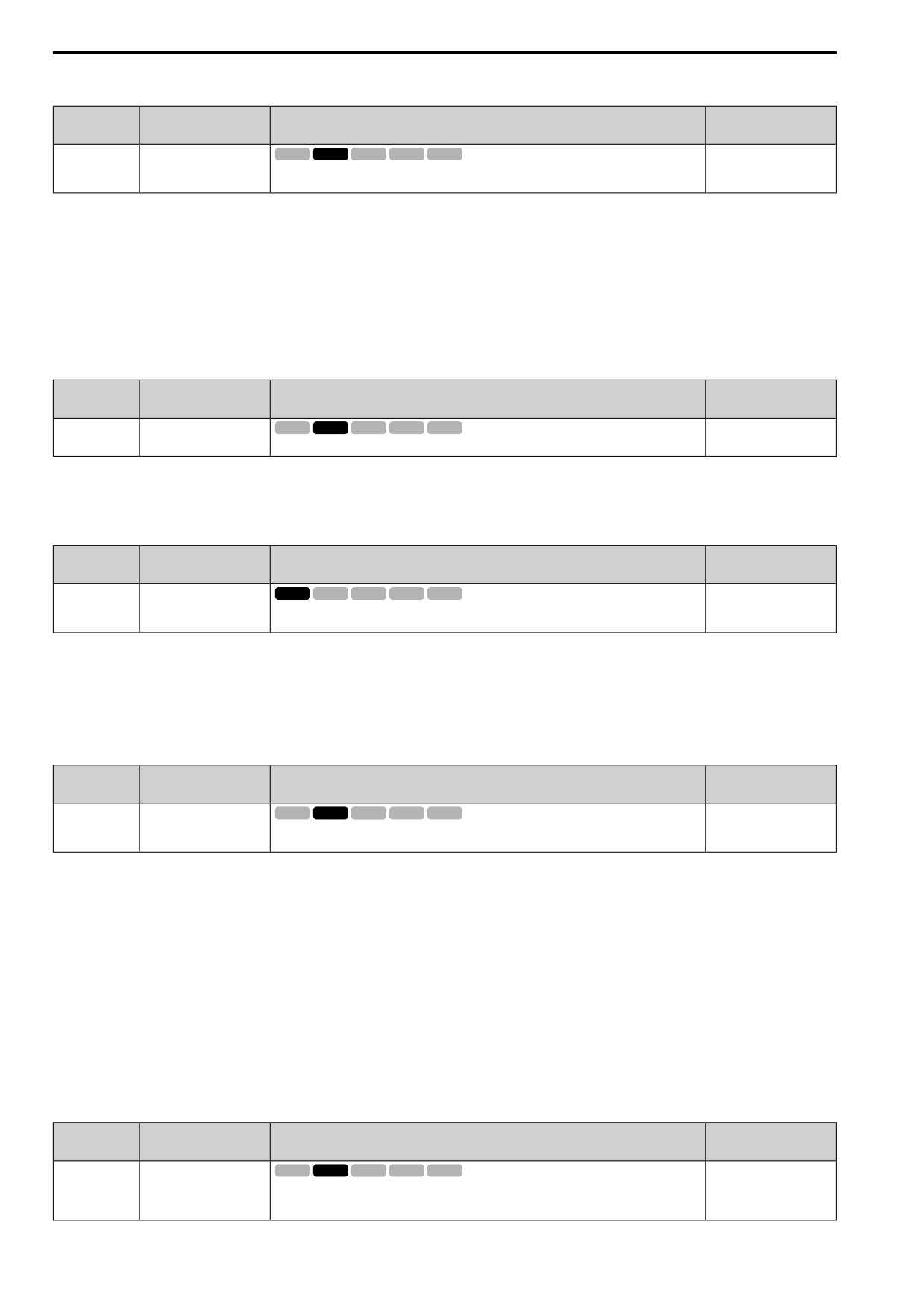
12.11 T: AUTOTUNING
■ T1-09: Motor NoLoad Current
No.
Default
Name
Description
(Hex.)
(Range)
T1-09
Motor NoLoad Current
V/f
OLV OLV/PM AOLV/PM EZOLV
-
(0709)
Sets the no-load current of the motor.
(0A - T1-04; max. of
2999.9)
Note:
The display units are different for different models:
• 0.01 A: 2001 to 2042, B001 to B018, 4001 to 4023
• 0.1 A: 2056 to 2082, 4031 to 4060
The value shown is the no-load current that the drive automatically calculates from the values set in T1-02 [Motor
Rated Power] and T1-04 [Motor Rated Current]. Set the no-load current shown on the motor test report. If the
motor test report is not available, do not change this parameter.
■ T1-10: Motor Rated Slip Frequency
No.
Default
Name
Description
(Hex.)
(Range)
T1-10
Motor Rated Slip
V/f
OLV OLV/PM AOLV/PM EZOLV
-
Frequency
(070A)
Sets motor rated slip.
(0.000 - 20.000 Hz)
Shows 0.000 Hz as the default value. Set the rated slip shown on the motor test report. If the motor test report is
not available, do not change this parameter.
■ T1-11: Motor Iron Loss
No.
Default
Name
Description
(Hex.)
(Range)
T1-11
Motor Iron Loss
V/f
OLV OLV/PM AOLV/PM EZOLV
Determined by E2-11 or
E4-11
(070B)
Sets the iron loss for calculating the energy-saving coefficient.
(0 - 65535 W)
Note:
The default setting is different for different motor codes and motor parameter settings.
The value shown is the E2-10 [Motor Iron Loss] or E4-10 [M2 Iron Loss] for the motor output set in T1-02
[Motor Rated Power]. If the motor test report is available, enter the motor iron loss value to T1-11.
■ T1-12: Test Mode Selection
No.
Default
Name
Description
(Hex.)
(Range)
T1-12
Test Mode Selection
V/f
OLV OLV/PM AOLV/PM EZOLV
0
(0BDB)
Sets the function to enable Test Mode after Stationary Auto-Tuning. When you can operate the
(0, 1)
motor with a light load attached after Stationary Auto-Tuning is complete, enable this parameter.
0 : No
1 : Yes
After Auto-Tuning, the drive automatically sets E2-02 [Mot Rated Slip] and E2-03 [Mot No-Load Current] when
you operate the motor for the first time in Drive Mode.
Note:
After Auto-Tuning is complete and you set the drive to Drive Mode, operate the motor in these conditions:
• Make sure that you connect all wiring between the drive and motor
• Make sure that a mechanical brake on the motor shaft is not locked
• Keep the motor-load ratio at 30%
• Hold constant speed for longer than 1 second at a minimum of 30% of the speed set in E1-06 [Base Frequency] (the default setting is
the same as the maximum frequency).
■ T1-13: No-load Voltage
No.
Default
Name
Description
(Hex.)
(Range)
T1-13
No-load Voltage
V/f
OLV OLV/PM AOLV/PM EZOLV
T1-03 × 0.9
(0BDC)
Sets the no-load voltage of the motor. When the no-load voltage at rated speed is available, for
(200 V Class: 0.0 - 255.0 V,
example on the motor test report, set the voltage in this parameter. If the no-load voltage is not
400 V Class: 0.0 - 510.0 V)
available, do not change this parameter.
718
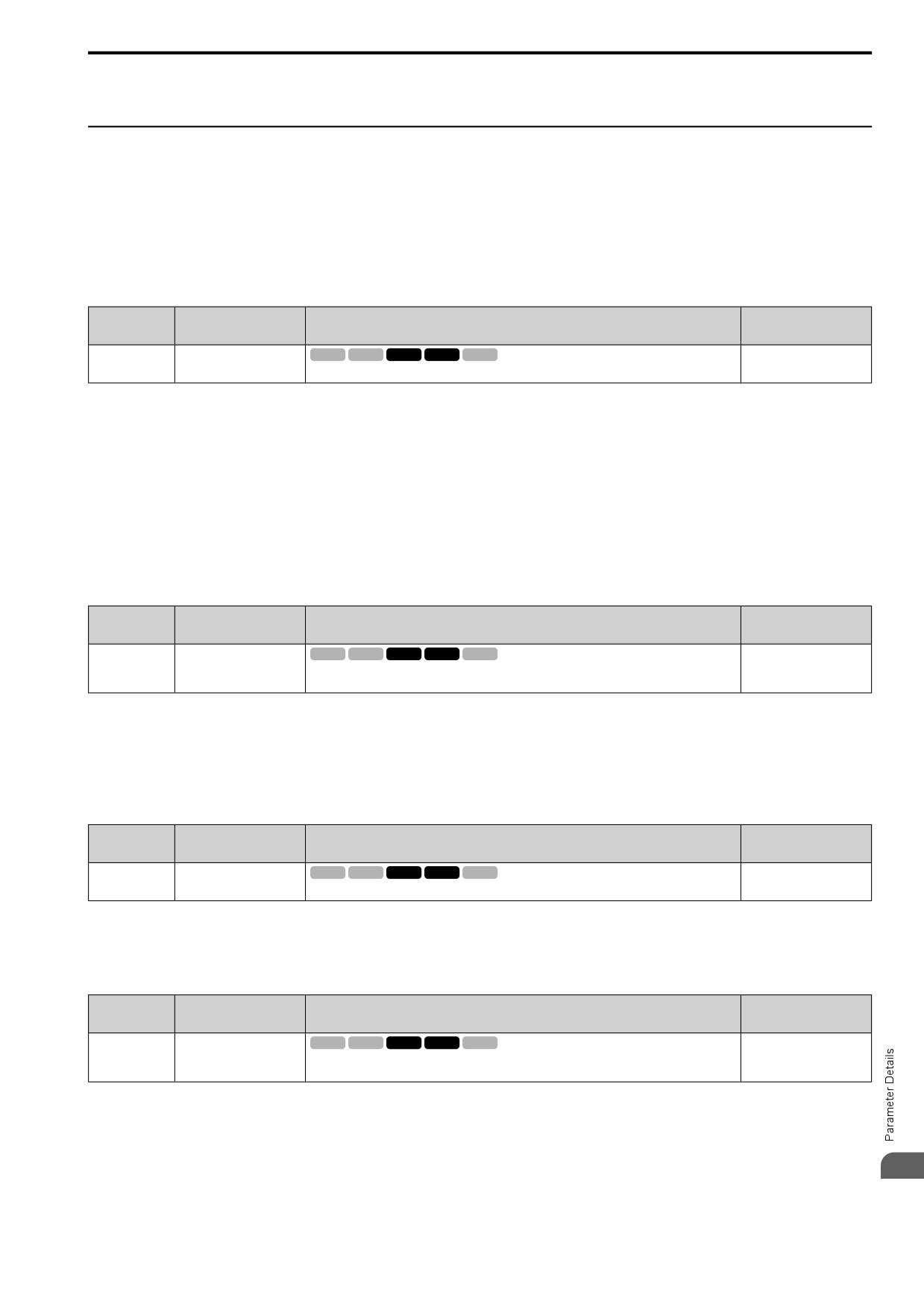
12.11 T: AUTOTUNING
Note:
To get the same qualities as a Yaskawa 1000-series drive or previous series drive, set this parameter = T1-03 [Motor Rated Voltage].
◆ T2: PM MOTOR
T2 parameters set the Auto-Tuning input data for PM motor tuning.
Note:
The drive automatically sets these PM motor parameters:
• E1: V/F PARAMETER MOTOR 1
• E5: PM MOTOR SETTINGS
■ T2-01: PM AutoTune Mode Select
No.
Default
Name
Description
(Hex.)
(Range)
T2-01
PM AutoTune Mode Select
V/f
OLV OLV/PM AOLV/PM EZOLV
0
(0750)
Sets the type of Auto-Tuning for PM motors.
(Determined by A1-02)
Note:
The manufacturer recommends Rotational (Ld, Lq, R, back-EMF) for specialized motors. Rotational Auto-Tuning rotates the motor to
measure the actual induction voltage constants for more accurate control than Stationary Auto-Tuning.
0 : PM Motor Parameter Settings
1 : PM Static Full AutoTune
2 : PM Static R Autotune
4 : PM Rotary Autotune
5 : High Frequency Injection
■ T2-02: PMMot Code Selection
No.
Default
Name
Description
(Hex.)
(Range)
T2-02
PMMot Code Selection
V/f
OLV OLV/PM AOLV/PM EZOLV
Determined by A1-02 and
o2-04
(0751)
If the drive is operating an SMRD, SMRA, or SSR1 series Yaskawa PM motor, enter the PM
motor code in to align with the rotation speed and motor output.
(0000 - FFFF)
Enter the motor code to automatically set parameters T2-03 to T2-14. When you are operating a specialized motor
or a non-Yaskawa motor, set T2-02 = FFFF and enter the data from the motor nameplate or the motor test report.
You can only enter the permitted PM motor codes. Different drive control methods will accept different PM motor
codes.
■ T2-03: PMMot Motor Type
No.
Default
Name
Description
(Hex.)
(Range)
V/f
OLV OLV/PM AOLV/PM EZOLV
T2-03
PMMot Motor Type
1
(0752)
Sets the type of PM motor the drive will operate.
(0, 1)
0 : IPM Motor
1 : SPM Motor
■ T2-04: PMMot Rated Power
No.
Default
Name
Description
(Hex.)
(Range)
T2-04
PMMot Rated Power
V/f
OLV OLV/PM AOLV/PM EZOLV
Determined by o2-04, C6-
01
(0730)
Uses the units set in o1-58 [Mot Capacity Unit] to set the PM motor rated output power.
(0.00 - 650.00 kW)
12
719
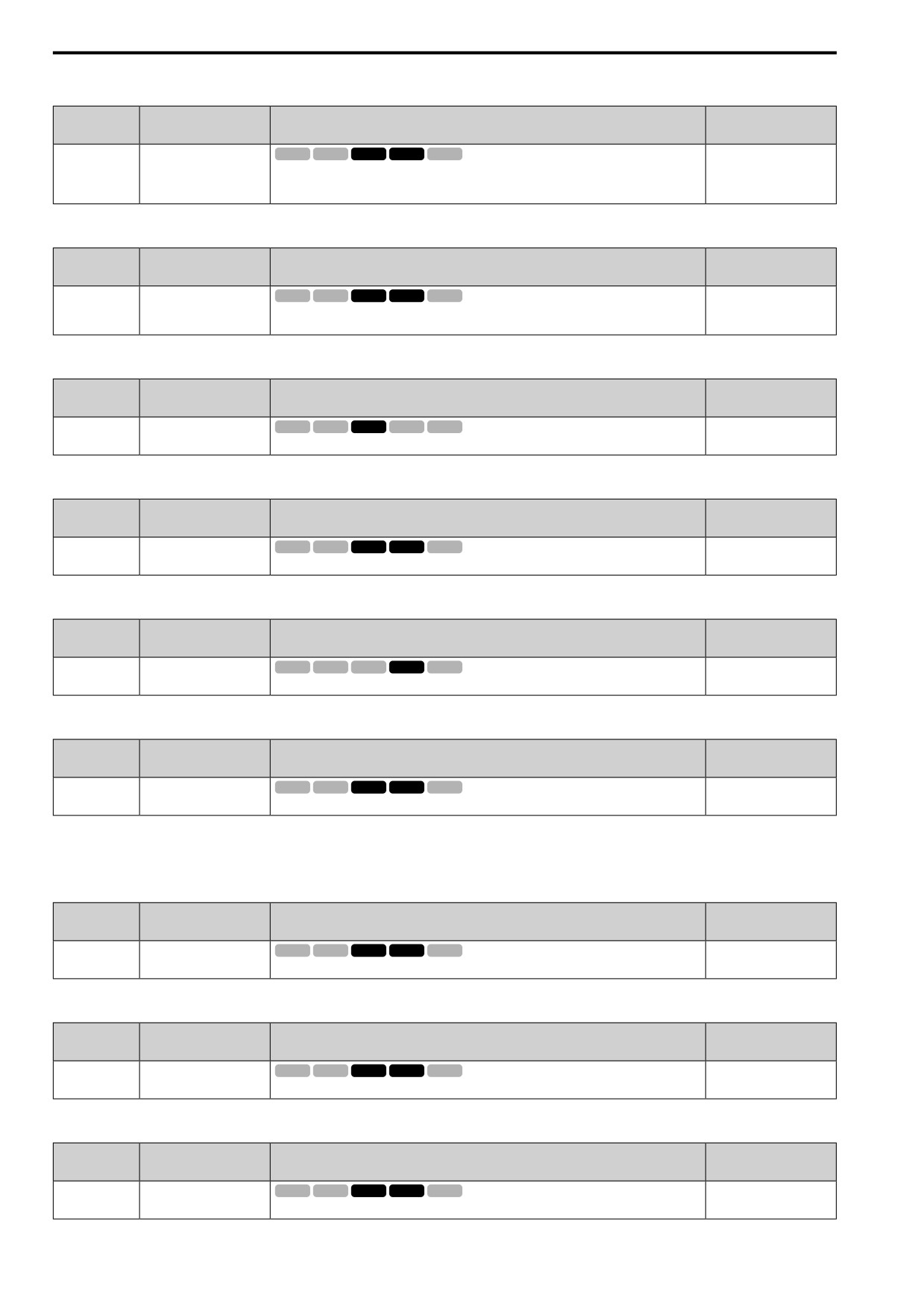
12.11 T: AUTOTUNING
■ T2-05: PMMot Rated Voltage
No.
Default
Name
Description
(Hex.)
(Range)
T2-05
PMMot Rated Voltage
V/f
OLV OLV/PM AOLV/PM EZOLV
200 V Class: 200.0 V, 400
V: 400.0 V
(0732)
Sets the rated voltage (V) of the motor.
(200 V Class: 0.0 - 255.0 V,
400 V Class: 0.0 - 510.0 V)
■ T2-06: PMMot Rated Current
No.
Default
Name
Description
(Hex.)
(Range)
T2-06
PMMot Rated Current
V/f
OLV OLV/PM AOLV/PM EZOLV
Determined by o2-04
(0733)
Sets the rated current (A) of the motor.
(10% to 200% of the drive
rated current)
■ T2-07: PMMot Base Frequency
No.
Default
Name
Description
(Hex.)
(Range)
T2-07
PMMot Base Frequency
V/f
OLV OLV/PM AOLV/PM EZOLV
87.5 Hz
(0753)
Sets the base frequency (Hz) of the motor.
(0.0 - 590.0 Hz)
■ T2-08: PMMot Poles Number
No.
Default
Name
Description
(Hex.)
(Range)
T2-08
PMMot Poles Number
V/f
OLV OLV/PM AOLV/PM EZOLV
6
(0734)
Sets the number of motor poles.
(2 - 48)
■ T2-09: PMMot Base Speed
No.
Default
Name
Description
(Hex.)
(Range)
V/f
OLV OLV/PM AOLV/PM EZOLV
T2-09
PMMot Base Speed
1750 min-1 (r/min)
(0731)
Sets the motor base speed (min-1 (r/min)).
(0 - 34500 min-1 (r/min))
■ T2-10: PMMot Stator Resistance
No.
Default
Name
Description
(Hex.)
(Range)
T2-10
PMMot Stator Resistance
V/f
OLV OLV/PM AOLV/PM EZOLV
Determined by T2-02
(0754)
Sets the stator resistance for each motor phase.
(0.000 - 65.000 Ω)
Note:
This parameter does not set line-to-line resistance.
■ T2-11: PMMot dAxis Inductance
No.
Default
Name
Description
(Hex.)
(Range)
T2-11
PMMot dAxis Inductance
V/f
OLV OLV/PM AOLV/PM EZOLV
Determined by T2-02
(0735)
Sets the d-axis inductance of the motor on a per phase basis.
(0.00 - 600.00 mH)
■ T2-12: PMMot qAxis Inductance
No.
Default
Name
Description
(Hex.)
(Range)
V/f
OLV OLV/PM AOLV/PM EZOLV
T2-12
PMMot qAxis Inductance
Determined by T2-02
(0736)
Sets the q-Axis inductance of the motor on a per phase basis.
(0.00 - 600.00 mH)
■ T2-13: KE Unit Selection
No.
Default
Name
Description
(Hex.)
(Range)
T2-13
KE Unit Selection
V/f
OLV OLV/PM AOLV/PM EZOLV
1
(0755)
Sets the units that the drive uses to set the induced voltage constant.
(0, 1)
720
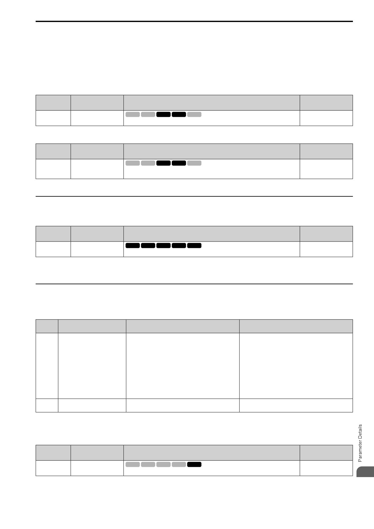
12.11 T: AUTOTUNING
0 : mV/rpm
1 : mV/(rad/sec)
Note:
• When T2-13 = 0, the drive will use E5-24 [PM BackEMF L-L Vrms (mV/rpm)] and will automatically set E5-09 [PM BackEMF Vpeak
(mV/(rad/ s))] = 0.0.
• When T2-13 = 1, the drive will use E5-09 and will automatically set E5-24 = 0.0.
■ T2-14: PMMot KE Voltage Constant
No.
Default
Name
Description
(Hex.)
(Range)
T2-14
PMMot KE Voltage
V/f
OLV OLV/PM AOLV/PM EZOLV
Determined by T2-13
Constant
(0737)
Sets the motor induced voltage constant (Ke).
(0.0
- 2000.0)
■ T2-15: PullInCurrLv@PM Motor Tuning
No.
Default
Name
Description
(Hex.)
(Range)
T2-15
PullInCurrLv@PM Motor
V/f
OLV OLV/PM AOLV/PM EZOLV
30%
Tuning
(0756)
Sets the level of the pull-in current as a percentage of E5-03 [PM Mot Rated Current (FLA)].
(0 - 120%)
Usually it is not necessary to change this setting.
If the load inertia is high, increase the setting value.
◆ T3: ASR
■ T3-00: Control Loop Tune Selection
No.
Default
Name
Description
(Hex.)
(Range)
T3-00
Control Loop Tune
V/f
OLV OLV/PM AOLV/PM EZOLV
2
Selection
(1198)
Sets the type of Control Auto-Tuning.
(2, 3)
2 : Dec Rate Tuning
3 : KEB Tuning
◆ T4: SIMPLE VECTOR
Use T4 parameters to input the data necessary for motor parameter Auto-Tuning when A1-02 =
8 [Control
Method = EZ Vector]. Two modes are available.
T4-01
Operational overview
Items input for tuning
Items tuned
Setting
0
Follow the instructions in the setup
• T4-02 [Motor Type Selection]
• E9-01 [Motor Type Selection]
wizard on the keypad to manually
• T4-03 [Motor Max Revolutions]
• E9-02 [Maximum Speed]
enter the necessary motor
parameters.
• T4-04 [Motor Rated Revolutions]
• E9-03 [Rated Speed]
• T4-05 [Motor Rated Frequency] *1
• E9-04 [Base Frequency]
• T4-06 [Motor Rated Voltage]
• E9-05 [Base Voltage]
• T4-07 [Motor Rated Current]
• E9-06 [Motor Rated Current]
• T4-08 [Motor Rated Capacity]
• E9-07 [Motor Rated Power (kW)]
• T4-09 [Motor Poles Number]
• E9-08 [Motor Pole Count]
• E9-09 [Motor Rated Slip]
• E9-10 [Motor L-L Resistance]
1
Do only line-to-line resistance
Motor Rated Current
E9-10 [Motor L-L Resistance]
tuning.
*1
When you use a PM motor or a synchronous reluctance motor, it is not necessary to enter the rated frequency. The drive will use the
rated rotation speed and number of motor poles to automatically calculate the rated frequency.
■ T4-01: EZ Tune Mode Selection
No.
Default
Name
Description
(Hex.)
(Range)
V/f
OLV OLV/PM AOLV/PM EZOLV
T4-01
EZ Tune Mode Selection
0
(3130)
Sets the type of Auto-Tuning for EZOLV control.
(0, 1)
12
0 : Motor Constant
721
12.11 T: AUTOTUNING
1 : Static R Autotune
■ T4-02: Motor Type Selection
No.
Default
Name
Description
(Hex.)
(Range)
T4-02
Motor Type Selection
V/f
OLV OLV/PM AOLV/PM EZOLV
0
(3131)
Sets the type of motor.
(0, 1, 2)
0 : IM
Induction Motor
1 : PM
Permanent Magnet Motor
2 : SynRM
Synchronous Reluctance Motor
■ T4-04: Motor Rated Revolutions
No.
Default
Name
Description
(Hex.)
(Range)
T4-04
Motor Rated Revolutions
V/f
OLV OLV/PM AOLV/PM EZOLV
-
(3133)
Sets rated rotation speed (min-1) of the motor.
((40 Hz to 120 Hz) × 60
×
2/E9-08)
■ T4-05: Motor Rated Frequency
No.
Default
Name
Description
(Hex.)
(Range)
T4-05
Motor Rated Frequency
V/f
OLV OLV/PM AOLV/PM EZOLV
Determined by E9-01 and
o2-04
(3134)
Sets the rated frequency (Hz) of the motor.
(40.0 - 120.0 Hz)
Note:
When T4-02 = 1, 2 [Motor Type Selection = PM, SynRM], input is not necessary because it assumes: Motor Rated Revolutions/60 ×
Number of Motor Poles/2.
■ T4-06: Motor Rated Voltage
No.
Default
Name
Description
(Hex.)
(Range)
V/f
OLV OLV/PM AOLV/PM EZOLV
T4-06
Motor Rated Voltage
200 V Class: 200.0 V, 400
(3135)
Sets the rated voltage (V) of the motor.
V: 400.0 V
(200 V Class: 0.0 - 255.0
V,400 V Class: 0.0 - 510.0
V)
■ T4-07: Motor Rated Current
No.
Default
Name
Description
(Hex.)
(Range)
T4-07
Motor Rated Current
V/f
OLV OLV/PM AOLV/PM EZOLV
Determined by o2-04, C6-
01
(3136)
Sets the rated current (A) of the motor.
(10% to 200% of the drive
rated current)
Note:
The value set here becomes the base value for motor protection, the torque limit, and torque control.
■ T4-08: Motor Rated Capacity
No.
Default
Name
Description
(Hex.)
(Range)
T4-08
Motor Rated Capacity
V/f
OLV OLV/PM AOLV/PM EZOLV
Determined by E9-10
(3137)
Sets the motor rated power in the units set in o1-58 [Mot Capacity Unit].
(0.10 - 650.00 kW)
722
12.11 T: AUTOTUNING
■ T4-09: Motor Poles Number
No.
Default
Name
Description
(Hex.)
(Range)
T4-09
Motor Poles Number
V/f
OLV OLV/PM AOLV/PM EZOLV
Determined by E9-01
(3138)
Sets the number of motor poles.
(2 - 48)
12
723
12.11 T: AUTOTUNING
724
13
Glossary
Phrase
Definition
AOLV/PM
Advanced Open Loop Vector Control for Permanent Magnet Motors
Drive
Q2V
EDM
External Device Monitor
EZOLV
EZ Open Loop Vector Control
HD
Heavy Duty
IPM motor
Interior Permanent Magnet Motor
MFAI
Multi-Function Analog Input
MFAO
Multi-Function Analog Output
MFDI
Multi-Function Digital Input
MFDO
Multi-Function Digital Output
ND
Normal Duty
OLV
Open Loop Vector Control
OLV/PM
Open Loop Vector Control for Permanent Magnet Motors
PM Motor
Permanent Magnet Synchronous motor (generic name for IPM motors and SPM motors)
SIL
Safety Integrity Level
SPM motor
Surface Permanent Magnet Motor
V/f
V/f Control
725