Q2V Driving Quality. Technical Manual (Item code: Q2V-Axxxx-xxx, 2020) - page 18
12.8 L: PROTECTION
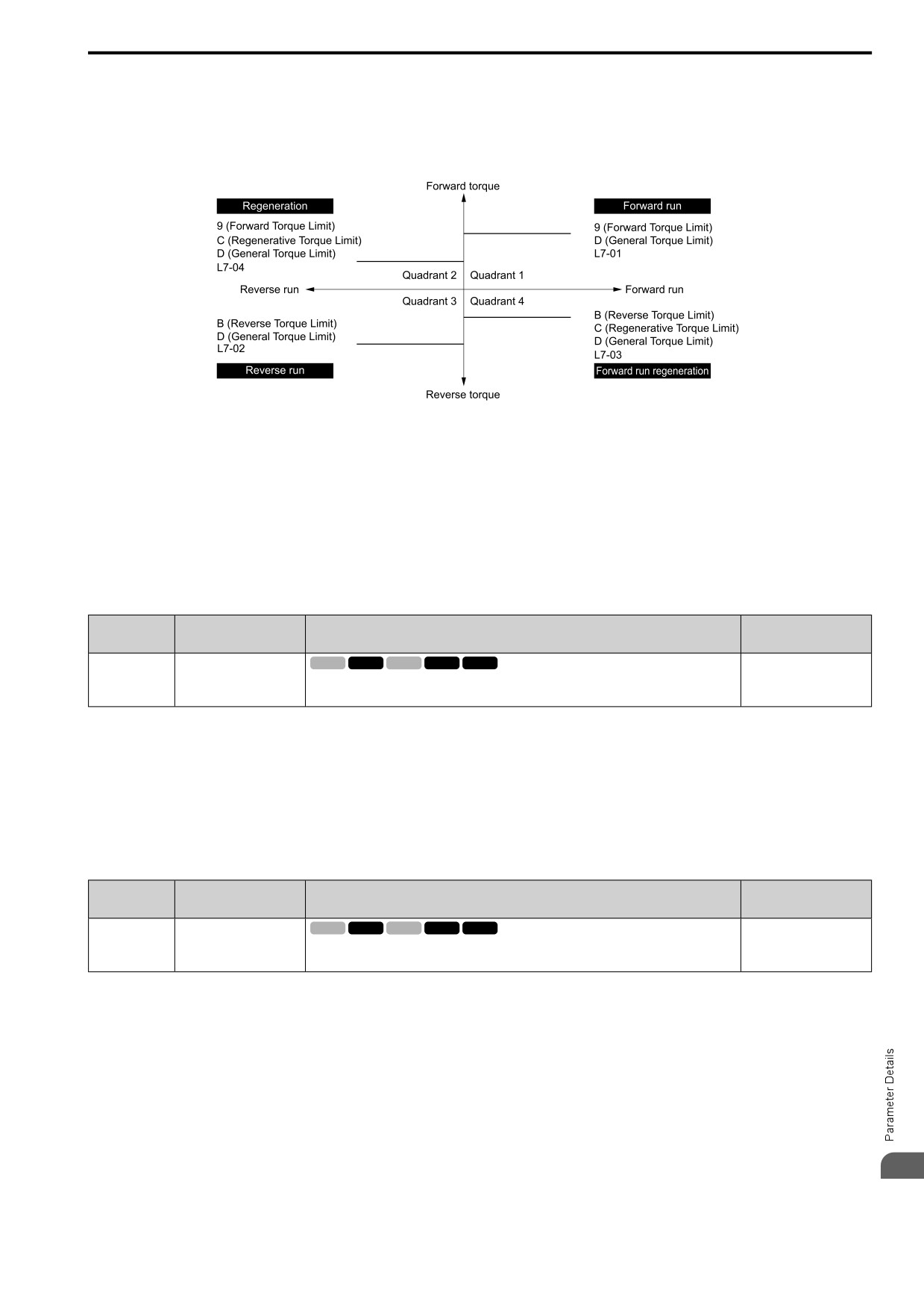
• Use MFAI to individually set the four torque limit quadrants. Set H3-02, H3-10 = 9, B, C [MFAI Function
Select = FW Trq Lim, Rev Trq Lim, RegenTrqLim].
• Use MFAI to set all four torque limit quadrants together. Set H3-02, H3-10 = D [GenerTrqLim].
• Use a communication option to set all four torque limit quadrants together.
This figure shows the configuration method for each quadrant.
Figure 12.127 Torque Limits and Analog Input Setting Parameters
Note:
• When L7-01 to L7-04 and analog inputs or communication option torque limits set torque limits for the same quadrant, the drive
enables the lowest value.
In this example of parameter settings, the torque limit for quadrant 1 is 130% and the torque limit for quadrants 2, 3, and 4 is 150%.
Settings: L7-01 = 130%, L7-02 to L7-04 = 200%, and MFAI torque limit = 150%
• The drive output current limits maximum output torque. The torque limit is 150% of the rated output current for HD and to 120% of
the rated output current for ND. The actual output torque is not more than the limits of the drive rated output current when you set the
torque limit to a high value.
■ L7-01: FW Torque Limit
No.
Default
Name
Description
(Hex.)
(Range)
V/f
OLV OLV/PM AOLV/PM EZOLV
L7-01
FW Torque Limit
200%
(04A7)
Sets the torque limit value for forward motoring as a percentage, where motor rated torque is the
(0 - 300%)
100% value.
RUN
Note:
• The lower torque limit is enabled when you set the torque limit by the following method.
-Set H3-02 or H3-10 = 9, D [MFAI Function Select = FW Trq Lim, GenerTrqLim].
-Use a communication option to set the torque limits
• You must think about drive capacity when a large quantity of torque is necessary. If you set the value too high, the drive can detect oC
[Overcurrent].
• If you set the value too low with large loads, the motor can stall.
■ L7-02: RV Torque Limit
No.
Default
Name
Description
(Hex.)
(Range)
L7-02
RV Torque Limit
V/f
OLV OLV/PM AOLV/PM EZOLV
200%
(04A8)
Sets the torque limit value for reversed motoring as a percentage, where motor rated torque is the
(0 - 300%)
100% value.
RUN
Note:
• The lower torque limit is enabled when you set the torque limit by the following method.
- Set H3-02 or H3-10 = 9, D [MFAI Function Select = FW Trq Lim, GenerTrqLim].
- Use a communication option to set the torque limits
• You must think about drive capacity when a large quantity of torque is necessary. If you set the value too high, the drive can detect oC
[Overcurrent].
• If you set the value too low with large loads, the motor can stall.
12
667
12.8 L: PROTECTION
■ L7-03: FW Reg. TrqLimit
No.
Default
Name
Description
(Hex.)
(Range)
L7-03
FW Reg. TrqLimit
V/f
OLV OLV/PM AOLV/PM EZOLV
200%
(04A9)
Sets the torque limit value for forward regenerative conditions as a percentage of the motor rated
(0 - 300%)
torque.
RUN
Note:
• The lower torque limit is enabled when you set the torque limit by the following method.
- Set H3-02 or H3-10 = 9, D [MFAI Function Select = FW Trq Lim, GenerTrqLim].
- Use a communication option to set the torque limits
• You must think about drive capacity when a large quantity of torque is necessary. If you set the value too high, the drive can detect oC
[Overcurrent].
• If you set the value too low with large loads, the motor can stall.
■ L7-04: RV Reg. TrqLimit
No.
Default
Name
Description
(Hex.)
(Range)
V/f
OLV OLV/PM AOLV/PM EZOLV
L7-04
RV Reg. TrqLimit
200%
(04AA)
Sets the torque limit value for reversed regenerative conditions as a percentage of the motor rated
(0 - 300%)
torque.
RUN
Note:
• Use this method to set the torque limit and enable the lower torque limit:
- Set H3-02 or H3-10 = 9, D [MFAI Function Select = FW Trq Lim, GenerTrqLim].
- Use a communication option to set the torque limits
• You must think about drive capacity when a large quantity of torque is necessary. If you set the value too high, the drive can detect oC
[Overcurrent].
• If you set the value too low with large loads, the motor can stall.
■ L7-06: TrqLimit Integral Time
No.
Default
Name
Description
(Hex.)
(Range)
L7-06
TrqLimit Integral Time
V/f
OLV OLV/PM AOLV/PM EZOLV
200 ms
(04AC)
Sets the integral time constant for the torque limit function.
(5 - 10000 ms)
Decrease the setting value to increase torque limit responsiveness when you use torque limits and L7-07 = 2
[TrqLimit@Acc/Decel = I-ctrl@Ac/Dec].
If there is hunting when torque limits are active, increase the setting value.
■ L7-07: TrqLimit@Acc/Decel
No.
Default
Name
Description
(Hex.)
(Range)
L7-07
TrqLimit@Acc/Decel
V/f
OLV OLV/PM AOLV/PM EZOLV
1
(04C9)
Sets the torque limit function during acceleration and deceleration.
(1, 2)
1 : P-ctrl@Ac/Dec
The torque limit function works with proportional control during acceleration and deceleration, and switches to
integral control at constant speed. Use this setting when quickly reaching the target speed is more important than
the torque limit during speed changes.
2 : I-ctrl@Ac/Dec
The torque limit function always uses integral control. Use this setting when a very accurate torque limit is
necessary during speed changes, for example in winding machine applications.
If you make the torque limit the most important, it can:
• Increase the acceleration and deceleration times.
• Not let the motor speed reach the frequency reference value during run at constant speed.
668
12.8 L: PROTECTION
■ L7-16: TrqLimit@Start
No.
Default
Name
Description
(Hex.)
(Range)
L7-16
TrqLimit@Start
V/f
OLV OLV/PM AOLV/PM EZOLV
1
(044D)
Assigns a time filter to allow the torque limit to build at start.
(0, 1)
0 : Disabled
There is torque limit at start without a delay time.
Use this setting to maximize the response time when sudden acceleration or deceleration at start is necessary.
1 : Enabled
There is a delay time of 64 ms at start to build the torque limit.
◆ L8: DRIVE PROTECTION
L8 parameters set protective functions that prevent faults such as overheating, phase loss, and ground faults.
■ L8-01: 3%ERF DBR Protection
No.
Default
Name
Description
(Hex.)
(Range)
V/f
OLV OLV/PM AOLV/PM EZOLV
L8-01
3%ERF DBR Protection
0
(04AD)
Sets the function to enable braking resistor protection with a Yaskawa ERF series braking resistor
(0, 1)
(3% ED) installed on the heatsink.
0 : Disabled
Disables braking resistor protection. Use this setting for dynamic braking options that are not Yaskawa ERF series
braking resistors.
1 : Enabled
Enables protection for Yaskawa ERF series braking resistors.
Note:
Set L8-01 = 1 and H2-01 to H2-03 = 4C [MFDO Function Select = BrkRes Fault]. Use a sequence to turn OFF power with MFDO.
■ L8-02: Overheat Alm Level
No.
Default
Name
Description
(Hex.)
(Range)
L8-02
Overheat Alm Level
V/f
OLV OLV/PM AOLV/PM EZOLV
Determined by o2-04, C6-
01
(04AE)
Sets the oH detection level in temperature.
(50 - 150 °C)
If the heatsink temperature is more than the temperature set in this parameter, the drive detects an overheat pre-
alarm. To enable this function, set one of H2-01 to H2-03 [MFDO Function Select] to 4E [Drive PreOH].
If the temperature increases to the overheat fault level, the drive will trigger an oH1 [Heatsink Overheat] fault and
stop operation.
■ L8-03: Overheat Pre-Alarm Selection
No.
Default
Name
Description
(Hex.)
(Range)
L8-03
Overheat Pre-Alarm
V/f
OLV OLV/PM AOLV/PM EZOLV
3
Selection
(04AF)
Sets the operation of drives when an oH alarm is detected.
(0 - 4)
0 : Ramp->Stop
The drive ramps the motor to stop in the deceleration time. The output terminal set for Fault [H2-01 to H2-03 =
3] activates.
1 : Coast->Stop
The output turns off and the motor coasts to stop. The output terminal set for Fault [H2-01 to H2-03 = 3]
activates.
2 : Fast Stop (C1-09)
12
The drive stops the motor in the deceleration time set in C1-09 [Fast Stop Time]. The output terminal set for Fault
[H2-01 to H2-03 = 3] activates.
669
12.8 L: PROTECTION
3 : Alarm Only
The keypad shows oH and the drive continues operation. The output terminal set for Alarm [H2-01 to H2-03 = 4]
activates.
4 : Run@L8-19 Rate
The drive decelerates to the level set in L8-19 [Frq Reduct@oHPre-Alarm] and continues operation. oH flashes
on the keypad.
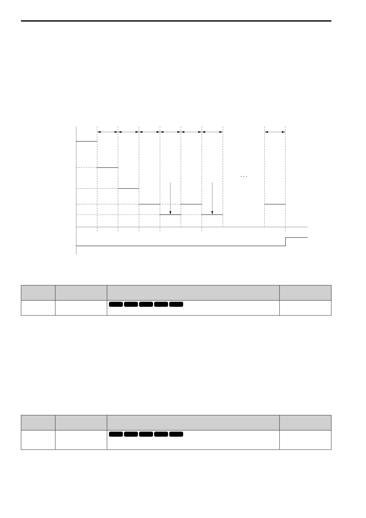
oH flashes on the keypad. When the alarm is output, the drive decelerates each 10 seconds. If the drive decelerates
10 times and the alarm continues to be output, the output terminal set for oH Pre-Alarm Reduction Limit [H2-01
to H2-03 = 4F] activates. When the alarm is not output during deceleration, the drive accelerates until it is at the
frequency reference that was applicable before the alarm was turned off. This figure shows the output of the alarm
and the drive operation at a decreased output frequency.
Output frequency
10 s
10 s
10 s
10 s
10 s
10 s
10 s
fref
oH
Alarm
fref × (L8-19)
oH Alarm
oH Alarm
oH
Cancel
Cancel
Alarm
fref × (L8-19)2
oH
oH
Alarm
Alarm
fref × (L8-19)3
fref × (L8-19)4
Time
1
2
3
4
5
6
10
oH Alarm count
Multi-function
ON
Digital Output Terminal
H2-01 through H2-03 = 4F
Figure 12.128 Drive Operation at a Decreased Output Frequency when the Overheat Alarm is Output
■ L8-05: In PhaseLoss Selection
No.
Default
Name
Description
(Hex.)
(Range)
L8-05
In PhaseLoss Selection
V/f
OLV OLV/PM AOLV/PM EZOLV
1
(04B1)
Sets the function to enable and disable input phase loss detection.
(0, 1)
0 : Disabled
1 : Enabled
The drive measures ripples in DC bus voltage to detect input phase loss.
The drive detects phase loss when power supply phase loss occurs or the main circuit capacitor becomes unusable,
which causes PF [Input Phase Loss] to show on the keypad.
Disable the detection of the input power supply phase loss function in these conditions:
• During deceleration
• The run command is not input
• The output current is less than 30% of the drive rated current.
■ L8-07: Out PhaseLoss Selection
No.
Default
Name
Description
(Hex.)
(Range)
L8-07
Out PhaseLoss Selection
V/f
OLV OLV/PM AOLV/PM EZOLV
0
(04B3)
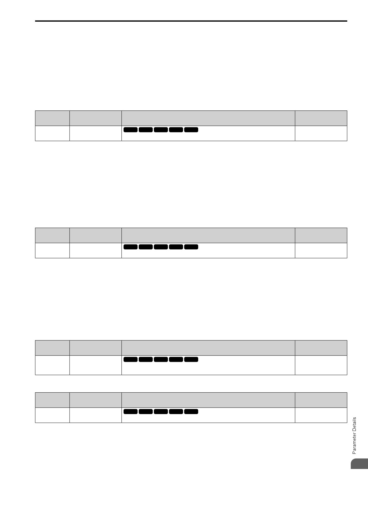
Sets the function to enable and disable output phase loss detection. The drive starts output phase
(0 - 2)
loss detection when the output current decreases to less than 5% of the drive rated current.
Note:
The drive can incorrectly start output phase loss detection in these conditions:
• The motor rated current is very small compared to the drive rating.
• The drive is operating a PM motor with a small load.
670
12.8 L: PROTECTION
0 : Disabled
1 : 1PH Loss Det
If the drive loses one output phase, it will trigger LF [Output Phase Loss].
The output turns off and the motor coasts to stop.
2 : 2/3PH Loss Det
If the drive loses more than one output phase, it will trigger LF [Output Phase Loss].
The output turns off and the motor coasts to stop.
■ L8-09: Ground Fault Selection
No.
Default
Name
Description
(Hex.)
(Range)
V/f
OLV OLV/PM AOLV/PM EZOLV
L8-09
Ground Fault Selection
Determined by o2-04
(04B5)
Sets the function to enable and disable ground fault protection.
(0, 1)
0 : Disabled
The drive will not detect ground faults.
1 : Enabled
If there is high leakage current or a ground short circuit in one or two output phases, the drive will detect GF
[Ground Fault].
Note:
If the ground path impedance is low, oC [Overcurrent], SC [Out Short Circuit or IGBT Fault], or ov [DC Bus Overvoltage] can stop the
motor.
■ L8-10: Fan Operate Selection
No.
Default
Name
Description
(Hex.)
(Range)
L8-10
Fan Operate Selection
V/f
OLV OLV/PM AOLV/PM EZOLV
1
(04B6)
Sets operation of the heatsink cooling fan.
(1 - 3)
1 : Dur Run (OffDly)
The drive turns on the fan when a Run command is active.
2 : Always On
The fan turns on when you supply power to the drive. When you release the Run command and the delay time set
in L8-11 [Fan Off-Delay Time] is expired, the fan stops. his setting extends the fan lifetime.
3 : Fan ON @Heating of Drive
The fan turns on when the drive detects that the main circuit is overheating.
■ L8-11: Fan Off-Delay Time
No.
Default
Name
Description
(Hex.)
(Range)
L8-11
Fan Off-Delay Time
V/f
OLV OLV/PM AOLV/PM EZOLV
60 s
(04B7)
Sets the length of time that the drive will wait before it stops the cooling fan after it cancels the
(0 - 300 s)
Run command when L8-10 = 1 [Fan Operate Selection = Dur Run (OffDly)].
■ L8-12: Ambient Temperature Setting
No.
Default
Name
Description
(Hex.)
(Range)
V/f
OLV OLV/PM AOLV/PM EZOLV
L8-12
Ambient Temperature
40 °C
Setting
(04B8)
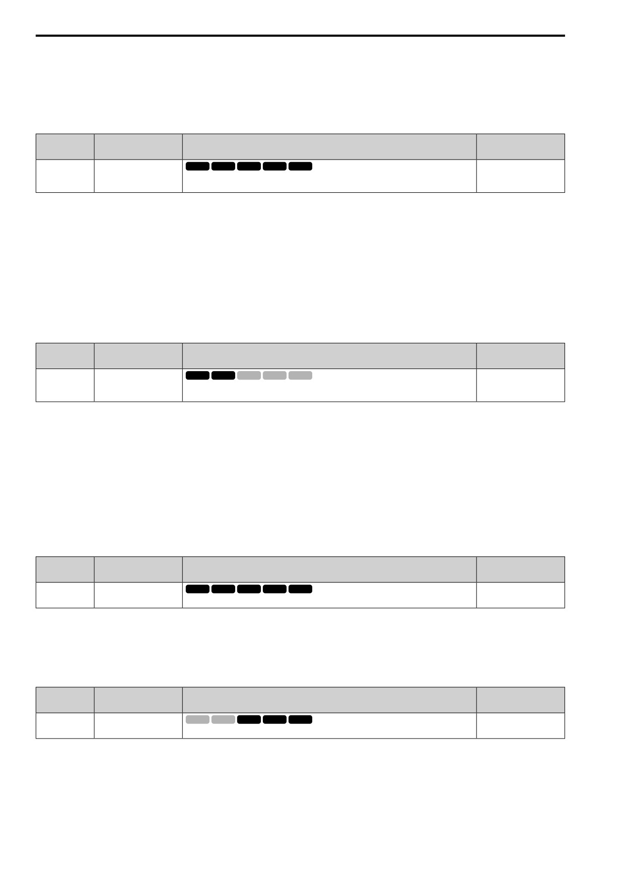
Sets the ambient temperature of the drive installation area.
(-10 °C - +60 °C)
Note:
The setting range changes when the L8-35 [Installation Selection] value changes:
• 0 [IP00/IP20/Open-Chassis]: -10 °C to +60 °C
• 1 [Side-by-Side Mounting]: -10 °C to +50 °C
• 2 [UL Type 1]: -10 °C to +50 °C
12
• 3 [Ext. Heatsink]: -10 °C to +50 °C
671
12.8 L: PROTECTION
The drive automatically adjusts the drive rated current to the best value as specified by the set temperature. Set the
ambient temperature of the area where you install the drive to a value that is more than the drive rating.
Refer to Derating Depending on Ambient Temperature on page 303 for information about derating as specified by
ambient temperature.
■ L8-15: oL2@LoSpeed Selection
No.
Default
Name
Description
(Hex.)
(Range)
L8-15
oL2@LoSpeed Selection
V/f
OLV OLV/PM AOLV/PM EZOLV
1
(04BB)
Sets the function to decrease drive overload at low speeds to prevent damage to the main circuit
(0, 1)
transistor during low speed operation (at 6 Hz or slower) to prevent oL2 [Drive Overloaded].
Note:
Contact the manufacturer or your nearest sales representative before disabling this function at low speeds. If you frequently operate
drives with high output current in low speed ranges, it can cause heat stress and decrease the life span of drive IGBTs.
0 : Disabled
The drive does not decrease the overload protection level.
1 : Enabled
When the drive detects oL2 during low speed operation, it automatically decreases the overload detection level.
At zero speed, the drive derates the overload by 50%.
■ L8-18: Soft CurrLim Selection
No.
Default
Name
Description
(Hex.)
(Range)
L8-18
Soft CurrLim Selection
V/f
OLV OLV/PM AOLV/PM EZOLV
1
(04BE)
Set the software current limit selection function to prevent damage to the main circuit transistor
(0, 1)
caused by too much current.
0 : Disabled
When the output current is at the software current limit value, the drive does not restrict the output voltage.
Note:
The drive may detect an oC [Overcurrent] when loads are particularly heavy or the acceleration time is particularly short.
1 : Enabled
When the output current is at the software current limit value, the drive decreases output voltage to decrease
output current.
When the output current decreases to the software current limit level, the drive starts usual operation.
■ L8-19: Frq Reduct@oHPre-Alarm
No.
Default
Name
Description
(Hex.)
(Range)
V/f
OLV OLV/PM AOLV/PM EZOLV
L8-19
Frq Reduct@oHPre-Alarm
0.8
(04BF)
Sets the ratio at which the drive derates the frequency reference during an oH alarm.
(0.1
- 0.9)
When these two conditions are correct, this function is enabled:
• L8-03 = 4 [Overheat Pre-Alarm Selection = Run@L8-19 Rate]
• oH alarm is output
■ L8-27: OverCurr Det Gain
No.
Default
Name
Description
(Hex.)
(Range)
L8-27
OverCurr Det Gain
V/f
OLV OLV/PM AOLV/PM EZOLV
300.0%
(04DD)
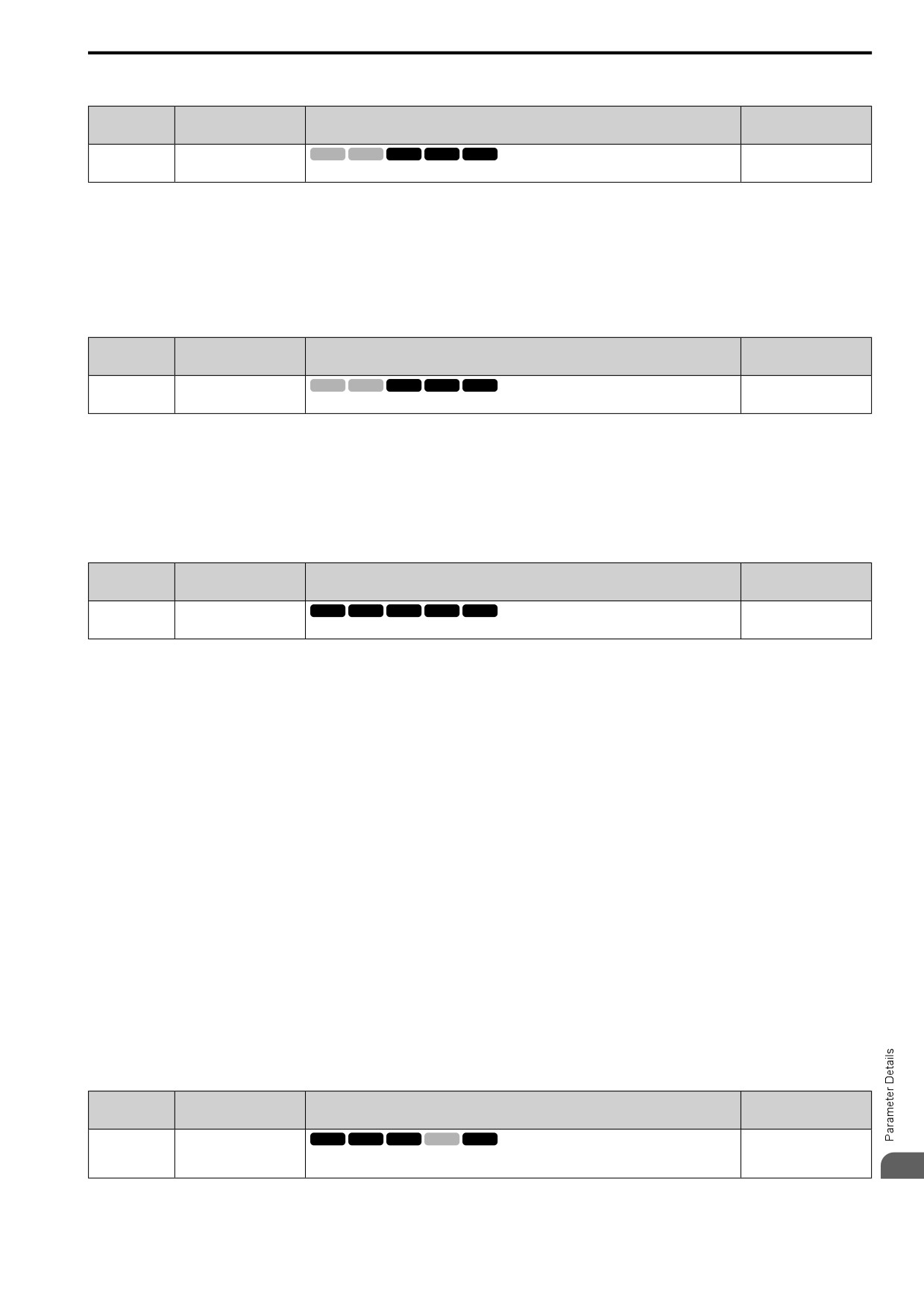
Sets the PM motor overcurrent detection level as a percentage of the motor rated current value.
(0.0
- 1000.0%)
Note:
• If the setting value for L8-27 is the same or almost the same as the setting value for L7-xx [Torque Limit], the drive can detect oC2
[Overcurrent2].
• This function is disabled when you set L8-27 = 0.0. Under usual circumstances, do not set L8-27 = 0.0.
• If the drive rated current is much higher than the motor rated current, PM motor magnets can demagnetize when current flows at the
drive overcurrent detection level. When you set a low overcurrent detection level to prevent PM motor demagnetization, make sure that
you adjust L8-27.
672
12.8 L: PROTECTION
■ L8-29: LF2 Unbalance Selection
No.
Default
Name
Description
(Hex.)
(Range)
L8-29
LF2 Unbalance Selection
V/f
OLV OLV/PM AOLV/PM EZOLV
1
(04DF)
Sets the function to detect LF2.
(0, 1)
This function prevents damage to PM motors. Current unbalance can heat a PM motor and demagnetize the
magnets. When the current is unbalanced, the drive will detect LF2 to stop the motor and prevent damage to the
motor.
0 : Disabled
1 : Enabled
■ L8-31: LF2 Detect Time
No.
Default
Name
Description
(Hex.)
(Range)
L8-31
LF2 Detect Time
V/f
OLV OLV/PM AOLV/PM EZOLV
3
(04E1)
Sets the LF2 [Output Current Imbalance] detection time.
(1 - 100)
When the output current is unbalanced for longer than the time set in L8-31, the drive detects LF2.
Note:
• Set L8-29 = 1 [LF2 Unbalance Selection = Enabled] to enable L8-31.
• If the drive incorrectly detects LF2, increase L8-31 in 5-unit increments.
• The keypad shows L8-31 when E9-01 = 1 [Motor Type Selection = PM] in EZ Vector Control.
■ L8-35: Installation Selection
No.
Default
Name
Description
(Hex.)
(Range)
L8-35
Installation Selection
V/f
OLV OLV/PM AOLV/PM EZOLV
0
(04EC)
Sets the type of drive installation.
(0 - 3)
Note:
• Parameter A1-03 [Init Parameters] does not initialize this parameter.
• This parameter is set to the correct value when the drive is shipped. Side-by-Side installation
-Change the value only in these conditions:
-When you install a UL Type 1 kit on an IP20/UL Open Type drive to convert the drive to an IP20/UL Type 1 drive.
-Mounting a standard drive with the heatsink outside the enclosure panel.
The overload protection detection level for the drive is automatically adjusted to the optimal value in accordance
with the setting value. Refer to Derating Depending on Ambient Temperature on page 303 for information about
derating as specified by ambient temperature.
0 : IP00/IP20/Open-Chassis
Use this setting to install IP20/UL Open Type drives.
Make sure that there is 30 mm (1.18 in) minimum of space between drives or between the drive and side of the
enclosure panel.
1 : Side-by-Side Mounting
Use this setting to install more than one drive side-by-side.
2 : ULType 1
Use this setting to install IP20/UL Type 1 or IP55 drives.
3 : Ext. Heatsink
Use this setting when the heatsink (cooling fin) is outside the control panel.
■ L8-40: Carrier Red Off-Delay Time
No.
Default
Name
Description
(Hex.)
(Range)
L8-40
Carrier Red Off-Delay Time
V/f
OLV OLV/PM AOLV/PM EZOLV
Determined by A1-02
(04F1)
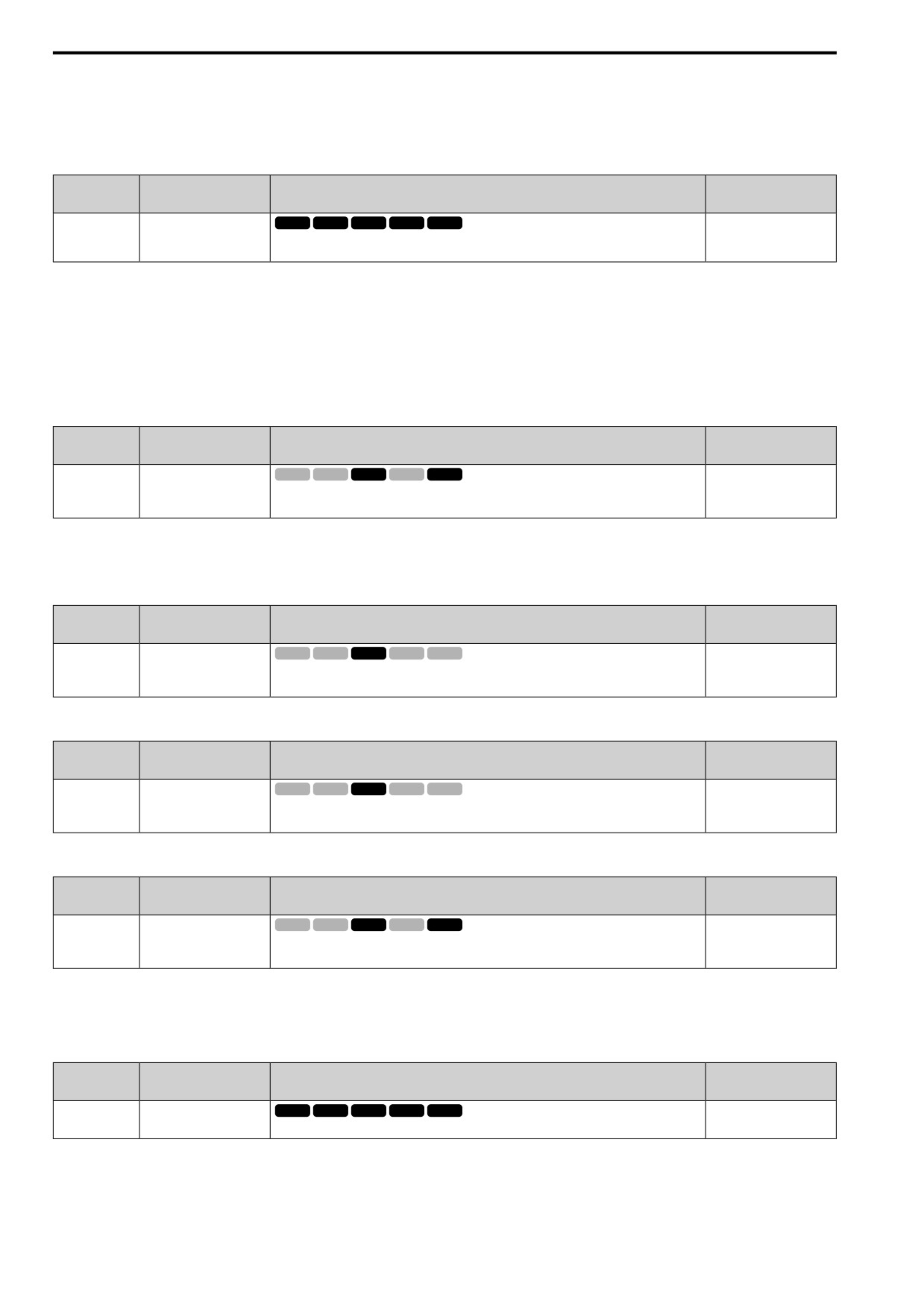
Sets the length of time until the automatically reduced carrier frequency returns to the condition
(0.00 - 2.00 s)
before the reduction.
12
673
12.8 L: PROTECTION
Set L8-40 ≠ 0.00 to enable the carrier frequency reduction function during start-up. When operation starts, the
drive automatically decreases the carrier frequency. When the time set in L8-40 is expired, the carrier frequency
returns to the value set in C6-02 [Carrier Frequency Selection].
■ L8-41: HCA alarm Selection
No.
Default
Name
Description
(Hex.)
(Range)
L8-41
HCA alarm Selection
V/f
OLV OLV/PM AOLV/PM EZOLV
0
(04F2)
Sets the function to cause an HCA [Current Alarm] when the output current is more than 150% of
(0, 1)
the drive rated current.
0 : Disabled
The drive will not detect HCA.
1 : Enabled
If the output current is more than 150% of the drive rated current, the drive will detect HCA.
The MFDO terminal set for an Alarm [H2-01 to H2-03 = 4] activates.
■ L8-51: STPo Current Level
No.
Default
Name
Description
(Hex.)
(Range)
L8-51
STPo Current Level
V/f
OLV OLV/PM AOLV/PM EZOLV
0.0%
(0471)
Sets the STPo [Motor Step-Out Detected] detection level as a percentage of the motor rated
(0.0
- 300.0%)
current.
Expert
Note:
The detection level is automatically calculated when L8-51 = 0.
■ L8-52: STPo Integral Level
No.
Default
Name
Description
(Hex.)
(Range)
L8-52
STPo Integral Level
V/f
OLV OLV/PM AOLV/PM EZOLV
1.0
(0472)
Sets the detection level for STPo [Motor Step-Out Detected] related to the ACR integral value.
(0.1
- 2.0)
Expert
■ L8-53: STPo Integral Time
No.
Default
Name
Description
(Hex.)
(Range)
V/f
OLV OLV/PM AOLV/PM EZOLV
L8-53
STPo Integral Time
1.0 s
(0473)
Sets the length of time until the drive detects STPo after it is more than the value of L8-51 [STPo
(1.0 - 10.0 s)
Current Level].
Expert
■ L8-54: STPo Id Diff Detection
No.
Default
Name
Description
(Hex.)
(Range)
L8-54
STPo Id Diff Detection
V/f
OLV OLV/PM AOLV/PM EZOLV
1
(0474)
Sets the Id deviation detection function for STPo [Motor Step-Out Detected].
(0, 1)
Expert
0 : Disable
1 : Enabled
■ L8-55: DB IGBT Protection
No.
Default
Name
Description
(Hex.)
(Range)
L8-55
DB IGBT Protection
V/f
OLV OLV/PM AOLV/PM EZOLV
1
(045F)
Sets the protection function for the internal braking transistor.
(0, 1)
0 : Disable
Disables braking transistor protection.
Use this setting, if enabling the braking transistor can cause an rF [Braking Resistor Fault] in these conditions:
674
12.8 L: PROTECTION
• With a regenerative converter, for example D1000.
• With a regenerative unit, for example R1000.
• When connecting braking resistor options to the drive, for example CDBR units.
• Without an internal braking transistor.
1 : Enabled
Protects internal braking transistor when using a braking transistor or optional braking resistors.
■ L8-56: StallP@Acc Activation Time
No.
Default
Name
Description
(Hex.)
(Range)
L8-56
StallP@Acc Activation
V/f
OLV OLV/PM AOLV/PM EZOLV
5000 ms
Time
(047D)
Sets the length time that the acceleration stall prevention function can continue to operate before
(100 - 5000 ms)
the drive detects an STPo [Motor Step-Out Detected].
Expert
Note:
If this value is too small, it can cause incorrect detection of STPo. If this value is too large, the drive will not detect STPo.
■ L8-57: StallP Retry Counts
No.
Default
Name
Description
(Hex.)
(Range)
L8-57
StallP Retry Counts
V/f
OLV OLV/PM AOLV/PM EZOLV
10
(047E)
Sets the number of times the acceleration stall prevention function can operate until speeds agree
(1 - 10 times)
before the drive detects an STPo [Motor Step-Out Detected].
Expert
Note:
If this value is too small, it can cause incorrect detection of STPo. If this value is too large, the drive will not detect STPo.
■ L8-90: STPo Detect Level
No.
Default
Name
Description
(Hex.)
(Range)
V/f
OLV OLV/PM AOLV/PM EZOLV
L8-90
STPo Detect Level
Determined by A1-02
(0175)
Sets the detection level that the control fault must be equal to or more than to cause an STPo
(0 - 5000 times)
[Motor Step-Out Detected].
Expert
This function detects when PM motors are not synchronized.
The drive cannot detect when motors are not synchronized because the frequency reference is low during start up
and the motor is locked. If fault detection is necessary in these conditions, set the control fault detection level to
enable detection of desynchronization because of motor locking. Increase the setting in 5-unit increments.
■ L8-93: Lso Detect Time
No.
Default
Name
Description
(Hex.)
(Range)
L8-93
Lso Detect Time
V/f
OLV OLV/PM AOLV/PM EZOLV
1.0 s
(073C)
Sets the length of time the drive will wait to start baseblock after detecting LSo [Low Speed Motor
(0.0 - 10.0 s)
Step-Out].
Expert
Set this parameter to 0.0 to disable the function.
■ L8-94: Lso Detect Level
No.
Default
Name
Description
(Hex.)
(Range)
L8-94
Lso Detect Level
V/f
OLV OLV/PM AOLV/PM EZOLV
3%
(073D)
Sets the detection level for LSo [Low Speed Motor Step-Out] as a percentage of E1-04 [Max
(0 - 10%)
Output Frequency].
Expert
■ L8-95: Lso Amount
No.
Default
Name
Description
(Hex.)
(Range)
12
L8-95
Lso Amount
V/f
OLV OLV/PM AOLV/PM EZOLV
10
(077F)
Sets the average count of LSo [Low Speed Motor Step-Out] detections.
(1 - 50 times)
Expert
675
12.9 n: SPECIAL
12.9
n: SPECIAL
n parameters set these functions:
• Function to prevent hunting
• High-slip braking
• Motor line-to-line resistance online tuning
• Fine-tune the parameters that adjust motor control
◆ n1: HUNTING PREVENTION
The Hunting Prevention function will not let low inertia or operation with a light load cause hunting. Hunting
frequently occurs when you have a high carrier frequency and an output frequency less than 30 Hz.
■ n1-01: HuntPrev Selection
No.
Default
Name
Description
(Hex.)
(Range)
HuntPrev Selection
V/f
OLV OLV/PM AOLV/PM EZOLV
n1-01
0
(0580)
Sets the function to prevent hunting.
(0, 1)
When drive response is more important than the decrease of motor vibration, disable this function.
0 : Disabled
1 : Enabled
■ n1-02: HuntPrev Gain Setting
No.
Default
Name
Description
(Hex.)
(Range)
HuntPrev Gain Setting
V/f
OLV OLV/PM AOLV/PM EZOLV
n1-02
1.00
(0581)
Sets the performance of the hunting prevention function. Usually it is not necessary to change this
(0.00
- 2.50)
parameter.
Expert
Adjust this parameter in these conditions:
• When n1-01 = 1, 2 [HuntPrev Selection = Enabled, Enabled (High Carrier)], if oscillation occurs when you
operate a motor with a light load, increase the setting value in 0.1-unit increments.
• When n1-01 = 1, 2, if the motor stalls, decrease the setting value in 0.1-unit increments.
■ n1-03: HuntPrev Time Constant
No.
Default
Name
Description
(Hex.)
(Range)
HuntPrev Time Constant
V/f
OLV OLV/PM AOLV/PM EZOLV
n1-03
Determined by o2-04
(0582)
Sets the primary delay time constant of the hunting prevention function. Usually it is not
(0 - 500 ms)
necessary to change this parameter.
Expert
Adjust this parameter in these conditions:
• Load inertia is large: Increase the setting value. If the setting value is too high, response will be slower. Also,
there will be oscillation when the frequency is low.
• Oscillation occurs at low frequencies: Decrease the setting value.
■ n1-05: HuntPrev Gain Reverse Mode
No.
Default
Name
Description
(Hex.)
(Range)
HuntPrev Gain Reverse
V/f
OLV OLV/PM AOLV/PM EZOLV
n1-05
0.00
Mode
(0530)
Sets the performance of the hunting prevention function. This parameter adjusts Reverse run.
(0.00
- 2.50)
Usually it is not necessary to change this parameter.
Expert
Note:
When you set n1-05 = 0, the value set in n1-02 [HuntPrev Gain Setting] is effective when the motor rotates in reverse.
Adjust this parameter in these conditions:
• When n1-01 = 1, 2 [HuntPrev Selection = Enabled, Enabled (High Carrier)], if oscillation occurs when you
operate a motor with a light load, increase the setting value in 0.1-unit increments.
676
12.9 n: SPECIAL
• When n1-01 = 1, 2, if the motor stalls, decrease the setting value in 0.1-unit increments.
■ n1-13: DCBus Stab.Control
No.
Default
Name
Description
(Hex.)
(Range)
DCBus Stab.Control
V/f
OLV OLV/PM AOLV/PM EZOLV
n1-13
0
(1B59)
Sets the oscillation suppression function for the DC bus voltage.
(0, 1)
Expert
0 : Disabled
1 : Enabled
Note:
If the DC bus voltage does not become stable with light loads and the drive detects ov [Overvoltage], set this parameter to 1.
■ n1-14: DCBus Stab Time
No.
Default
Name
Description
(Hex.)
(Range)
DCBus Stab Time
V/f
OLV OLV/PM AOLV/PM EZOLV
n1-14
100.0 ms
(1B5A)
Adjusts the responsiveness of the oscillation suppression function for the DC bus voltage. Set n1-
(50.0 - 500.0 ms)
13 = 1 [DCBus Stab.Control = Enabled] to enable this parameter.
Expert
Note:
Adjust this parameter in 100 ms increments.
◆ n2: AFR - AUTO FREQ REGULATION
The speed feedback detection reduction function (or AFR: Automatic Frequency Regulator) helps the speed
become stable when you suddenly apply or remove a load.
Note:
Before you change n2-xx parameters, do one of these procedures:
• Set the motor parameters and V/f pattern correctly.
• Do Rotational Auto-Tuning.
■ n2-01: AFR Gain
No.
Default
Name
Description
(Hex.)
(Range)
AFR Gain
V/f
OLV OLV/PM AOLV/PM EZOLV
n2-01
1.00
(0584)
Sets the gain of the AFR function as a magnification value. Usually it is not necessary to change
(0.00
- 10.00)
this setting.
Adjust this parameter in these conditions:
• If hunting or oscillation occurs with light loads, increase the setting value in 0.05-unit increments and examine
the response.
• When torque is not sufficient with heavy loads or to make the torque or speed response better, decrease the
setting value in 0.05-unit increments and examine the response.
■ n2-02: AFR Time 1
No.
Default
Name
Description
(Hex.)
(Range)
AFR Time 1
V/f
OLV OLV/PM AOLV/PM EZOLV
n2-02
50 ms
(0585)
Sets the time constant that sets the rate of change for the AFR function. Usually it is not necessary
(0 - 2000 ms)
to change this setting.
Adjust this parameter in these conditions:
• If there is hunting or oscillation with a light load, increase the setting value in 50 ms increments and examine
the response. If the load inertia is large, increase the setting value in 50 ms increments and examine the
response.
• If torque is not sufficient with a heavy load or if you must increase torque or speed responsiveness, decrease the
setting value in 10 ms increments and examine the response.
12
677
12.9 n: SPECIAL
Note:
• Set n2-02 ≤ n2-03 [AFR Time 1 ≤ AFR Time 2]. If n2-02 > n2-03, the drive will detect oPE08 [Parameter Selection Error].
• When you change the value in n2-02, also change the value in C4-02 [Trq Comp Delay Time] by the same ratio.
■ n2-03: AFR Time 2
No.
Default
Name
Description
(Hex.)
(Range)
AFR Time 2
V/f
OLV OLV/PM AOLV/PM EZOLV
n2-03
750 ms
(0586)
Sets the time constant that sets the speed difference of the AFR function. Use this parameter for
(0 - 2000 ms)
speed searches or regeneration. Usually it is not necessary to change this setting.
Adjust this parameter in these conditions:
• If the drive detects ov [Overvoltage] when acceleration stops under high-inertia loads, increase the setting value
in 50 ms increments.
If the drive detects ov when the load changes suddenly, increase the setting value in 50 ms increments.
• To increase the responsiveness of torque and speed, decrease the setting value in 10 ms increments and examine
the response.
Note:
• Set n2-02 ≤ n2-03 [AFR Time 1 ≤ AFR Time 2]. If n2-02 > n2-03, the drive will detect oPE08 [Parameter Selection Error].
• When you change the value in n2-03, also change the value in C4-06 [M2 Trq Comp Delay Time] by the same ratio.
◆ n3: HIGHSLIP/OVEREXCITATION BRAKE
n3 parameters configure High Slip Braking and Overexcitation Deceleration.
■ High Slip Braking (HSB)
High slip braking quickly decelerates motors without braking resistors.
This lets you stop a motor more quickly than with the ramp to stop processes. This function is best for
applications that do not frequently stop the motor, for example the fast stop function for high-inertia loads.
Braking starts when the MFDI for HiSlipBraking [H1-xx = 32] activates.
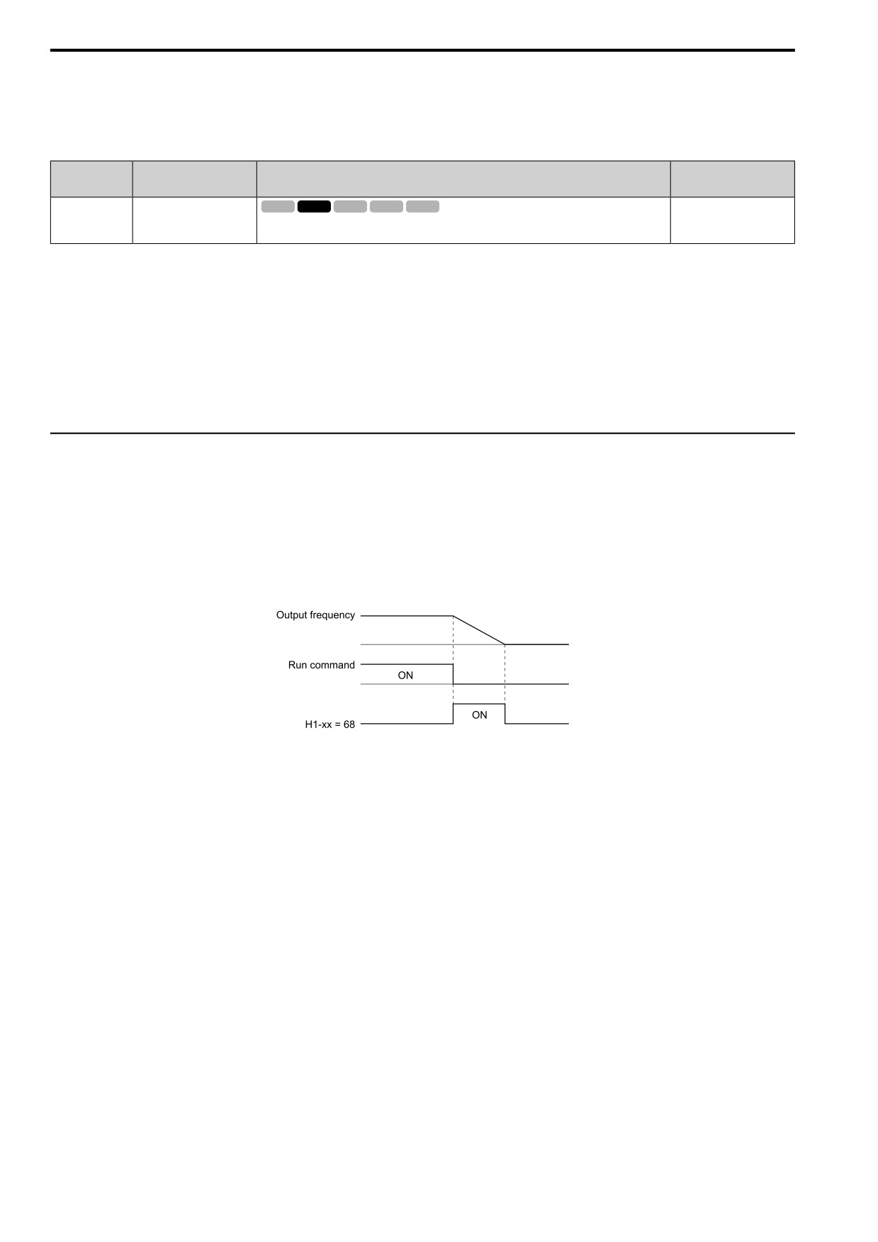
Figure 12.129 High Slip Braking Time Chart
An induction motor is necessary to use high slip braking. Set A1-02 = 0 [Control Method = V/f Control] to enable
high slip braking:
Principles of Operation
HSB increases motor slip by significantly decreasing the frequency supplied to the motor at the same time that
deceleration starts. A large quantity of current flows through the motor to increase the motor loss, and the motor
decelerates while the motor windings consume the regenerative energy.
The drive keeps the motor current at a constant level during deceleration to prevent overvoltage and do automatic
braking and it also keeps a slip level that causes the maximum quantity of deceleration torque.
High Slip Braking Precautions
• Do not use the high slip braking function in these applications:
- Frequent deceleration
- Deceleration time differences
- Continuous regenerative loads
- It is necessary to accelerate again during deceleration
• Motor loss increases during high slip braking. Use this function when the duty time factor is 5% ED or less and
the braking time is 90 seconds or less. The load inertia and motor characteristics have an effect on the braking
time.
678
12.9 n: SPECIAL
• The drive ignores the configured deceleration time during high slip braking. To stop motors in the configured
deceleration time, set L3-04 = 1 [StallP@Decel Enable = Enabled] and L3-50 = 3 [StallP@Decel Mode =
HiFlux Overexcitation].
• You cannot use high slip braking to decelerate deceleration at user-defined speeds. To decelerate at user-defined
speeds, use the overexcitation deceleration function.
• You cannot accelerate the motor again during high slip braking until you fully stop the motor and input the Run
command again.
• You cannot use high slip braking and the KEB Ride-Thru function at the same time. If you enable those two
functions, the drive will detect oPE03 [Multi-Function Input Setting Err].
■ Overexcitation Deceleration
Overexcitation deceleration quickly decelerates motors without braking resistors. This lets you stop a motor more
quickly than with the ramp to stop processes.
Overexcitation deceleration increases excitation current during deceleration to cause a large quantity of braking
torque through motor overexcitation. You can set the deceleration speed to adjust the deceleration time for
overexcitation deceleration. Overexcitation deceleration lets you accelerate the motor again during deceleration.
Enter the Run command during overexcitation deceleration to cancel overexcitation deceleration and accelerate
the drive to the specified speed.
To enable this function, set L3-04 = 1 [StallP@Decel Enable = Enabled] and L3-50 = 3, 4 [StallP@Decel Mode
= HiFlux Overexcitation, HiFlux2 Overexcitation].
When L3-04 = 4, the motor will decelerate for the Deceleration Times [C1-02, C1-04, C1-06, or C1-08]. If the
drive detects ov [Overvoltage], increase the deceleration time.
When L3-04 = 5, the drive uses the value in C1-02, C1-04, C1-06, or C1-08 to decelerate and it adjusts the
deceleration rate to keep the DC bus voltage at the level set in L3-17 [DCBus Regul.Level]. The load inertia and
motor characteristics have an effect on the braking time.
Notes on Overexcitation Deceleration
• Do not use Overexcitation Deceleration with a braking resistor.
• Do not use Overexcitation Deceleration for these applications. Connect a braking resistor to the drive as an
alternative to Overexcitation Deceleration.
- Frequent sudden decelerations
- Continuous regenerative loads
- Low inertia machines
- Machines that have no tolerance for torque ripples
• Motor loss increases during overexcitation deceleration. Use this function when the duty time factor is 5% ED
or less and the braking time is 90 seconds or less. The load inertia and motor characteristics have an effect on
the braking time.
• You can use overexcitation deceleration in OLV control, but this control method decreases the precision of
torque control and braking efficiency. Use V/f control for the best results.
• The drive disables these functions during braking with Overexcitation Deceleration 2:
- Hunting Prevention Function (V/f Control)
- Torque Limit Speed Control (OLV Control)
■ n3-01: HSB Dec Freq Width
No.
Default
Name
Description
(Hex.)
(Range)
HSB Dec Freq Width
V/f
OLV OLV/PM AOLV/PM EZOLV
n3-01
5%
(0588)
Sets the amount by which the output frequency is to be lowered during high-slip braking, as a
(1 - 20%)
percentage of E1-04 [Max Output Frequency], which represents the 100% value.
Expert
When you must detect ov [DC Bus Overvoltage] during high-slip braking, set this parameter to a large value.
12
679
12.9 n: SPECIAL
■ n3-02: HSB CurrLim Level
No.
Default
Name
Description
(Hex.)
(Range)
HSB CurrLim Level
V/f
OLV OLV/PM AOLV/PM EZOLV
n3-02
Determined by C6-01 and
L8-38
(0589)
Sets the maximum current output during high-slip braking as a percentage, where E2-01 [Mot
Rated Current (FLA)] is 100%. Also set the current suppression to prevent exceeding drive
(0 - 150%)
Expert
overload tolerance.
Note:
The upper limit to the setting range changes when the setting for C6-01 [Normal / Heavy Duty Selection] changes.
• 150% when C6-01 = 0 [HD Rating]
• 120% when C6-01 = 1 [ND Rating]
When you decrease the setting value for current suppression, it will make the deceleration time longer.
• When you must detect ov [DC Bus Overvoltage] during high-slip braking, set this parameter to a low value.
• If the motor current increases during high-slip braking, decrease the setting value to prevent burn damage in the
motor.
• The overload tolerance for the drive is 150% for Heavy Duty Rating (HD) and 110% for Normal Duty Rating
(ND).
■ n3-03: HSB DwellTime@Stop
No.
Default
Name
Description
(Hex.)
(Range)
HSB DwellTime@Stop
V/f
OLV OLV/PM AOLV/PM EZOLV
n3-03
1.0 s
(058A)
Sets the dwell time, a length of time when high-slip braking is ending and during which the motor
(0.0 - 10.0 s)
speed decreases and runs at a stable speed. For a set length of time, the drive will hold the actual
Expert
output frequency at the minimum output frequency set in E1-09.
If there is too much inertia or when the motor is coasting to a stop after high-slip braking is complete, increase the
setting value. If the setting value is too low, machine inertia can cause the motor to rotate after high-slip braking is
complete.
■ n3-04: HSB Overload Time
No.
Default
Name
Description
(Hex.)
(Range)
HSB Overload Time
V/f
OLV OLV/PM AOLV/PM EZOLV
n3-04
40 s
(058B)
Sets the time used to detect oL7 [High Slip Braking Overload], which occurs when the output
(30 - 1200 s)
frequency does not change during high-slip braking. Usually it is not necessary to change this
Expert
parameter.
If a force on the load side is rotating the motor or if there is too much load inertia connected to the motor, the
drive will detect oL7.
The current flowing to the motor from the load can overheat the motor and cause burn damage to the motor. Set
this parameter to prevent burn damage to the motor.
■ n3-13: OverExcBr Gain
No.
Default
Name
Description
(Hex.)
(Range)
OverExcBr Gain
V/f
OLV OLV/PM AOLV/PM EZOLV
n3-13
1.10
(0531)
Sets the gain value that the drive multiplies by the V/f pattern output value during overexcitation
(1.00
- 1.40)
deceleration to calculate the overexcitation level.
The V/f pattern output value goes back to its usual level after the motor stops or accelerates again to the frequency
reference speed.
The best value of this parameter changes when the flux saturation characteristics of the motor change.
• Gradually increase the value of n3-13 to 1.25 or 1.30 to increase the braking power of Overexcitation
Deceleration. If the gain is too much, the motor can have flux saturation and cause a large quantity of current to
flow. This can increase the deceleration time.
• Decrease the setting value if flux saturation causes overcurrent. If you increase the setting value, the drive can
detect oC [Overcurrent], oL1 [Motor Overload], and oL2 [Drive Overload]. Decrease the value of n3-21
[OverExcBr Current Level] to prevent oC and oL.
• Regular use of overexcitation deceleration or extended periods of overexcitation deceleration can increase
internal motor temperatures. Decrease the setting value in these conditions.
680
12.9 n: SPECIAL
• If ov [Overvoltage] occurs, increase the deceleration time.
■ n3-14: OverExcBr Harmonics Selection
No.
Default
Name
Description
(Hex.)
(Range)
OverExcBr Harmonics
V/f
OLV OLV/PM AOLV/PM EZOLV
n3-14
0
Selection
(0532)
Sets the function that injects harmonic signals during overexcitation deceleration.
(0, 1)
Expert
Enable this parameter to set a shorter deceleration time.
Note:
• If you frequently use overexcitation deceleration on a motor, the motor loss will increase the risk of burn damage.
• When you set this parameter to 1, the motor can make a loud excitation sound during overexcitation deceleration. If the excitation
sound is unwanted, set this parameter to 0 to disable the function.
0 : Disabled
1 : Enabled
The drive injects harmonic signals at the time of overexcitation deceleration. You can decrease the deceleration
time because motor loss increases.
■ n3-21: OverExcBr Current Level
No.
Default
Name
Description
(Hex.)
(Range)
OverExcBr Current Level
V/f
OLV OLV/PM AOLV/PM EZOLV
n3-21
100%
(0579)
Sets the upper limit of the current that is suppressed at the time of overexcitation deceleration as a
(0 - 150%)
percentage of the drive rated current.
If flux saturation during Overexcitation Deceleration makes the motor current become more than the value set in
this parameter, the drive will automatically decrease the overexcitation gain. If oC [Overcurrent], oL1 [Motor
Overload], or oL2 [Drive Overloaded] occur during overexcitation deceleration, decrease the setting value.
If repetitive or long overexcitation deceleration cause the motor to overheat, decrease the setting value.
■ n3-23: OverExcBr Operation
No.
Default
Name
Description
(Hex.)
(Range)
OverExcBr Operation
V/f
OLV OLV/PM AOLV/PM EZOLV
n3-23
1
(057B)
Sets the direction of motor rotation where the drive will enable overexcitation.
(1 - 3)
1 : Enabled@Both directions
2 : Enabled@FW direction
3 : Enabled@REV direction
Note:
When n3-23 = 2, 3, the drive enables overexcitation only in the direction of motor rotation in which a regenerative load is applied.
Increased motor loss can decrease ov [Overvoltage] faults.
◆ n5: FEED FORWARD CONTROL
Feed forward control increases the responsiveness of acceleration and deceleration as specified by the speed
reference.
Increase the values set in C5-01 and C5-03 [ASR PGain 1 and ASR PGain 2] to apply feed forward control to
machines that have low rigidity and are possible to have hunting and vibration or to machines that have a large
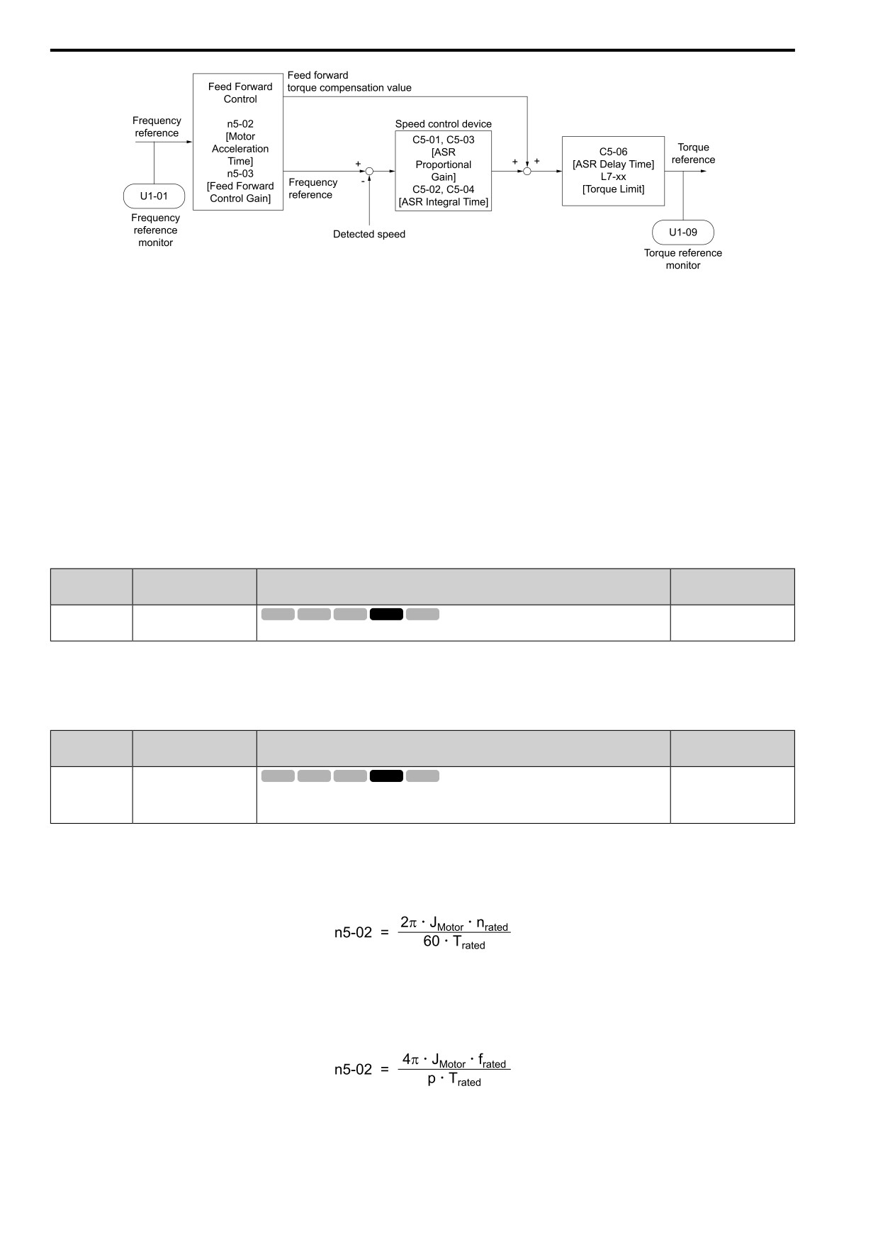
quantity of inertia. Refer to Figure 12.130 for more information about parameters related to feed forward control.
Set A1-02 = 6 [Control Method = PM AOLVector] to enable feed forward control.
Note:
• You cannot use feed forward control to increase responsiveness in applications where you apply loads externally during run at constant
speed.
• You cannot use feed forward control with motor 2.
12
681
12.9 n: SPECIAL
Figure 12.130 Configure Feed Forward Control
■ Before You Use Feed Forward Control
Do one of these procedures before you use feed forward control.
• Run Auto-Tuning to set motor parameters.
When you cannot do Auto-Tuning, manually set motor parameters with the information on the motor nameplate
or test reports. Set E2: MOTOR 1 PARAMETERS for induction motors. Set E5: PM MOTOR SETTINGS for PM
motors.
• Set C5: ASR - SPEED REGULATION individually to adjust the speed control loop (ASR).
• If you can connect a motor to a machine and rotate it during Auto-Tuning, do Inertia Tuning.
The drive automatically adjusts feed forward parameters during Inertia Tuning.
• If you cannot do Inertia Tuning, refer to Figure 12.130 and set the parameters related to feed forward control
individually.
■ n5-01: FF Control Selection
No.
Default
Name
Description
(Hex.)
(Range)
n5: FF Control Selection
V/f
OLV OLV/PM AOLV/PM EZOLV
n5-01
0
(05B0)
Sets the feed forward function.
(0, 1)
0 : Disabled
1 : Enabled
■ n5-02: Mot Inertia Acceleration Time
No.
Default
Name
Description
(Hex.)
(Range)
Mot Inertia Acceleration
V/f
OLV OLV/PM AOLV/PM EZOLV
n5-02
Determined by C6-01, E5-
Time
01, and o2-04
(05B1)
Sets the length of time for the motor to accelerate from the stopped to the maximum frequency
with a single motor at the rated torque. Inertia Tuning automatically sets the motor acceleration
(0.001 - 10.000 s)
time.
If you cannot do Inertia Tuning, calculate the motor acceleration time as shown here or measure the motor
acceleration time and set n5-02 to this value.
Calculate the Motor Acceleration Time
Use this formula to find the motor acceleration time:
• JMotor = Moment of inertia of motor (kg m2)
• nrated = Motor rated speed (min-1, r/min)
• Trated = Motor rated torque (N m)
You can also use this formula to find the motor acceleration time:
• frated = Motor rated frequency (Hz)
• P = Number of motor poles
682
12.9 n: SPECIAL
Calculate the Motor Acceleration Time
Use this procedure to calculate the motor acceleration time:
1. Use A1-02 [Control Method] to set the control method.
2. Disconnect the motor and load.
3. Run Auto-Tuning to set motor parameters.
When you cannot do Auto-Tuning, manually set motor parameters with the information on the motor
nameplate or test reports. Set the E2 parameters for induction motors. Set the E5 parameters for PM motors.
4. Set C5: ASR - SPEED REGULATION.
5. Set C1-01 [Accel Time 1] = 0.
6. Set L7-01 [FW Torque Limit] to 100%.
7. Set the frequency reference to the same value as the motor rated speed.
8. Measure the length of time for the motor to reach the rated speed.
Show U1-05 [Motor Speed] on the keypad and enter the Run command (forward run).
9. Stop the motor.
10. Set n5-02 to the measured motor acceleration time value.
Reset all of the parameters that you changed to the previous setting values.
■ n5-03: FF Control Gain
No.
Default
Name
Description
(Hex.)
(Range)
FF Control Gain
V/f
OLV OLV/PM AOLV/PM EZOLV
n5-03
1.00
(05B2)
Sets the ratio between load inertia and motor inertia. Inertia Tuning automatically sets the
(0.00
- 100.00)
Feedforward Control Gain value.
When you cannot do Inertia Tuning, use this procedure to set n5-03:
Set n5-02 [Mot Inertia Acceleration Time].
1. Connect the motor and load.
2. Set C1-01 [Accel Time 1] = 0.
3. Use L7-01 to L7-04 [Torque Limit] to set the expected test run torque limit levels.
4. Set the frequency reference as specified by the high speed range of the machine.
5. Measure the length of time for the motor to reach the command reference speed.
Show U1-05 [Motor Speed] on the keypad and enter the Run command.
6. Stop the motor.
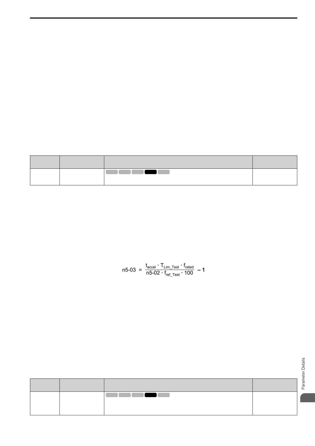
7. Replace the values in the this formula and set n5-03 to the value of the formula.
• taccel = Acceleration time (s)
• frated = Motor rated frequency (Hz)
• TLim_Test = Test run torque limit (%)
• fref_Test = Test run frequency reference (Hz)
WARNING! Sudden Movement Hazard. Machinery can accelerate suddenly. Do not use this function with machinery that must
not accelerate suddenly. Sudden starts can cause serious injury or death.
Reset all of the parameters that you changed to the previous setting values.
Note:
• If response to the speed reference is slow, increase the value set in n5-03.
• Increase the value set in n5-03 when response to the speed reference is slow.
-The speed is overshooting.
-A negative torque reference is output when acceleration ends.
■ n5-04: Speed Response Frequency
No.
Default
Name
Description
(Hex.)
(Range)
Speed Response Frequency
V/f
OLV OLV/PM AOLV/PM EZOLV
n5-04
Determined by A1-02
12
(05B3)
Sets the response frequency for the speed reference. Usually it is not necessary to change this
(0.00 - 500.00 Hz)
parameter.
RUN
Expert
683
12.9 n: SPECIAL
If you set n5-03 [FF Control Gain] too high, the motor speed will momentarily increase to more than the set
frequency.
◆ n6: ONLINE TUNING
n6 parameters are used to set the online tuning function for motor line-to-line resistance.
The Online Tuning for motor line-to-line resistance is used to prevent degradation of speed control accuracy due
to motor temperature fluctuation and motor stalls due to insufficient torque.
■ n6-01: Online Tune Selection
No.
Default
Name
Description
(Hex.)
(Range)
Online Tune Selection
V/f
OLV OLV/PM AOLV/PM EZOLV
n6-01
0
(0570)
Sets the type of motor data that Online Tuning uses for OLV control.
(0 - 2)
0 : Disabled
1 : Line-to-Line Resistance Tuning
The drive adjusts the motor line-to-line resistance during run. This procedure is applicable for speed values 6 Hz
and less. It also adjusts the motor resistance value to increase the overload capacity in the low speed range.
2 : VoltageAdjustment
The drive adjusts the output voltage during run to increase overload tolerance and minimize the effects of high
temperatures on speed precision.
Note:
Setting 2 is enabled only when b8-01 = 0 [eSave Ctrl Selection = Disabled].
■ n6-05: Online Tune Gain
No.
Default
Name
Description
(Hex.)
(Range)
Online Tune Gain
V/f
OLV OLV/PM AOLV/PM EZOLV
n6-05
1.0
(05C7)
Sets the compensation gain when n6-01 = 2 [Online Tune Selection = VoltageAdjustment].
(0.1
- 50.0)
Usually it is not necessary to change this parameter.
Expert
When you use a motor that has a large secondary circuit time constant, decrease the setting value.
If the drive detects oL1 [Motor Overload], increase the setting value in 0.1-unit increments.
◆ n7: SIMPLE VECTOR TUNING
The n7 parameters provide special adjustments for EZ Vector Control.
■ n7-01: LoFreq Damping Gain
No.
Default
Name
Description
(Hex.)
(Range)
LoFreq Damping Gain
V/f
OLV OLV/PM AOLV/PM EZOLV
n7-01
1.0
(3111)
Sets the oscillation suppression gain for the low speed range.
(0.1
- 10.0)
Expert
Note:
• If oscillation occurs in the low speed range, increase the acceleration time or increase the setting value in 0.5-unit increments.
• To get starting torque with the setting for C4-01 [Trq Comp Gain], decrease the setting value in 0.3-unit increments.
■ n7-05: TrqCtrl Response Gain
No.
Default
Name
Description
(Hex.)
(Range)
TrqCtrl Response Gain
V/f
OLV OLV/PM AOLV/PM EZOLV
n7-05
50
(3115)
Sets the response gain related to changes in the load.
(10 - 1000)
Expert
Note:
To make tracking related to load changes better, increase the setting value in 5-unit increments. If oscillation occurs during load
changes, decrease the setting value in 5-unit increments.
684
12.9 n: SPECIAL
■ n7-07: Speed Calc.Gain1
No.
Default
Name
Description
(Hex.)
(Range)
Speed Calc.Gain1
V/f
OLV OLV/PM AOLV/PM EZOLV
n7-07
15.0 Hz
(3117)
Sets the speed calculation gain during usual operation. Usually it is not necessary to change this
(1.0 - 50.0 Hz)
setting.
Expert
■ n7-08: Speed Calc.Gain2
No.
Default
Name
Description
(Hex.)
(Range)
Speed Calc.Gain2
V/f
OLV OLV/PM AOLV/PM EZOLV
n7-08
25.0 Hz
(3118)
Sets the speed calculation gain during a speed search.
(1.0 - 50.0 Hz)
Expert
Note:
When you increase the setting value, you can do a speed search of a motor rotating at a high frequency. If the setting value is too high,
the calculated speed will oscillate and a restart will fail. Decrease the setting value in these conditions.
■ n7-10: Pull-in SwitchSpeed
No.
Default
Name
Description
(Hex.)
(Range)
Pull-in SwitchSpeed
V/f
OLV OLV/PM AOLV/PM EZOLV
n7-10
10.0%
(311A)
Sets the speed range to operate with the pull-in current command. Drive rated frequency = 100%
(0.0
- 100.0%)
value. If there is a large quantity of oscillation when you operate in the low speed range, increase
Expert
the setting value.
Note:
• When the drive accelerates, it enables these settings:
-Motor speed ≤ n7-10 + n7-11 [Drv Mode Switch Hysteresis Band]: n8-51 [Ac/Dec Pull-In Current]
-Motor speed > n7-10 + n7-11: b8-01 [eSave Ctrl Selection]
• When the drive decelerates, it enables these settings:
-Motor speed ≤ n7-10: n8-51 [Ac/Dec Pull-In Current]
-Motor speed > n7-10: b8-01 [eSave Ctrl Selection]
• If there is a large quantity of oscillation when you operate in the low speed range, increase the setting value.
• When it is most important to save energy in the low speed range, decrease the setting value.
■ n7-17: Resist.Temp.Compensation
No.
Default
Name
Description
(Hex.)
(Range)
Resist.Temp.Compensation
V/f
OLV OLV/PM AOLV/PM EZOLV
n7-17
2
(3122)
Sets the function to adjust for changes in the motor resistance value caused by changes in the
(1 to 3)
temperature.
1 : Invalid
2 : Valid (1 Time)
3 : Valid (Every Time)
Note:
• For settings 1 and 2, the adjustment time can cause a delay before startup.
• For settings 1 and 2, the drive can set the line-to-line resistance value of E9-10 [Motor L-L Resistance].
• When the temperature will change at startup, use setting 2.
• To decrease the startup time, set this parameter to 0, then do line-to-line resistance tuning.
• If you will start from coasting, set this parameter to 0, then do line-to-line resistance tuning.
■ n7-19: FluxErr CompGain
No.
Default
Name
Description
(Hex.)
(Range)
FluxErr CompGain
V/f
OLV OLV/PM AOLV/PM EZOLV
n7-19
5000%
(3128)
Sets the gain for magnetic flux compensation. Usually it is not necessary to change this setting.
(0 - 50000%)
Expert
12
685
12.9 n: SPECIAL
◆ n8: PM MOTOR CONTROL TUNING
n8 parameters are used to make adjustments when controlling PM motors.
■ n8-01: PolPos Detection Current
No.
Default
Name
Description
(Hex.)
(Range)
PolPos Detection Current
V/f
OLV OLV/PM AOLV/PM EZOLV
n8-01
50%
(0540)
Sets, as a percentage, the Initial Rotor Position Estimated Current, taking the E5-03 [PM Mot
(0 - 100%)
Rated Current (FLA)] as the 100% value. Usually it is not necessary to change this setting.
Expert
The drive uses the Initial Rotor Position Estimated Current to detect the initial position of rotors.
Use the "Si" value on the motor nameplate, if available.
■ n8-02: Pole Align Current Level
No.
Default
Name
Description
(Hex.)
(Range)
Pole Align Current Level
V/f
OLV OLV/PM AOLV/PM EZOLV
n8-02
80%
(0541)
Sets the current at the time of polar attraction as a percentage where E5-03 [PM Mot Rated
(0 - 150%)
Current (FLA)] is 100%. Usually it is not necessary to change this setting.
Expert
The drive uses the polar pull-in current to attract the rotor after it detects the initial rotor position. When you
increase the value of n8-02, the starting torque also increases.
• If the motor does not track correctly at the time of the polar attraction, increase the value in 10% increments.
• If the motor oscillates at the time of the polar attraction, decrease the value in 10% increments.
■ n8-11: Observ.Calc Gain2
No.
Default
Name
Description
(Hex.)
(Range)
Observ.Calc Gain2
V/f
OLV OLV/PM AOLV/PM EZOLV
n8-11
Determined by n8-72
(054A)
Sets the gain for speed estimation. Usually it is not necessary to change this setting.
(0.0
- 1000.0)
Note:
When n8-72 = 1 [Spd Obs. Method Selection = Method 1], the default value is 50.0. When n8-72 = 2 [Method 2], the default value is
150.0.
■ n8-14: Polar Comp Gain3
No.
Default
Name
Description
(Hex.)
(Range)
Polar Comp Gain3
V/f
OLV OLV/PM AOLV/PM EZOLV
n8-14
1.000
(054D)
Sets the gain for speed estimation. Usually it is not necessary to change this setting.
(0.000
- 10.000)
Expert
■ n8-15: Polar Comp Gain4
No.
Default
Name
Description
(Hex.)
(Range)
Polar Comp Gain4
V/f
OLV OLV/PM AOLV/PM EZOLV
n8-15
0.500
(054E)
Sets the gain for speed estimation. Usually it is not necessary to change this setting.
(0.000
- 10.000)
Expert
■ n8-21: Mot Back-EMF (Ke) Gain
No.
Default
Name
Description
(Hex.)
(Range)
Mot Back-EMF (Ke) Gain
V/f
OLV OLV/PM AOLV/PM EZOLV
n8-21
0.90
(0554)
Sets the gain for speed estimation. Usually it is not necessary to change this setting.
(0.80
- 1.00)
Expert
686
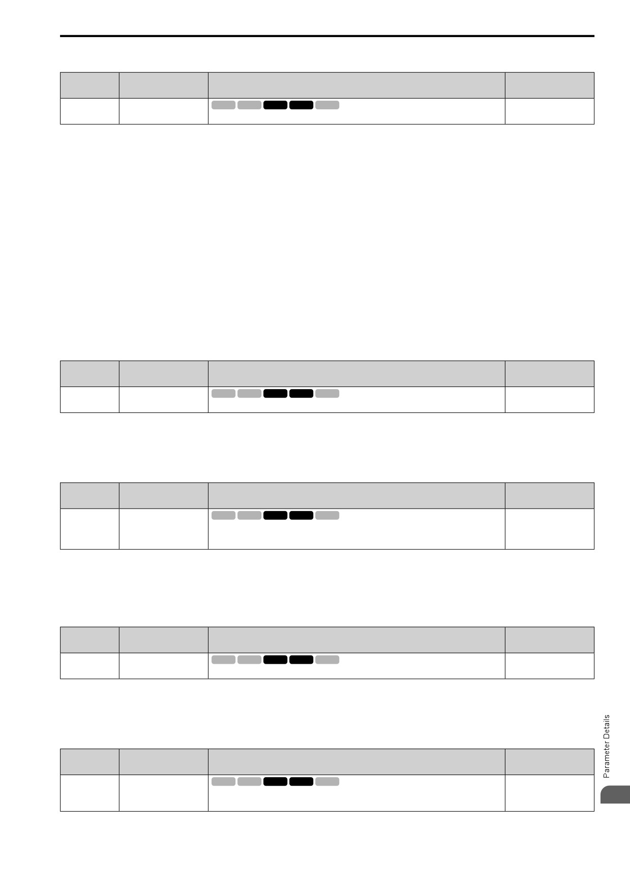
12.9 n: SPECIAL
■ n8-35: InitRotorPos Selection
No.
Default
Name
Description
(Hex.)
(Range)
InitRotorPos Selection
V/f
OLV OLV/PM AOLV/PM EZOLV
n8-35
Determined by A1-02
(0562)
Sets how the drive detects the position of the rotor when the motor starts.
(1 - 3)
Note:
• When you use an SPM motor, set n8-35 = 1.
• When you set n8-35 = 2, do High Frequency Injection Auto-Tuning.
• When you set n8-35 = 1 or 3, always evaluate the drive with the equipment being used for the application. If the drive incorrectly
detects the polarity, the motor can rotate in the direction opposite of the Run command.
1 : Pull-In
Starts the rotor with pull-in current.
2 : HiFreq Injection
Injects high frequency to detect the rotor position. This setting can cause a loud excitation sound when the motor
starts.
Note:
When you set 2, do High Frequency Injection Auto-Tuning.
3 : Pulse Injection
Inputs the pulse signal to the motor to detect the rotor position.
■ n8-36: HFI Signal Frequency
No.
Default
Name
Description
(Hex.)
(Range)
HFI Signal Frequency
V/f
OLV OLV/PM AOLV/PM EZOLV
n8-36
500 Hz
(0563)
Sets the injection frequency for high frequency injection.
(200 - 1000 Hz)
Note:
• Set n8-35 = 2 [InitRotorPos Selection = HiFreq Injection] or n8-57 = 1 [High-Freq Injection = Enabled] to enable this parameter.
• The drive automatically calculates this value when High Frequency Injection Auto-Tuning completes successfully.
■ n8-37: HFI Voltage Amplitude Level
No.
Default
Name
Description
(Hex.)
(Range)
HFI Voltage Amplitude
V/f
OLV OLV/PM AOLV/PM EZOLV
n8-37
20.0%
Level
(0564)
Sets the high frequency injection amplitude as a percentage where 200 V = 100% for 200 V class
(0.0
- 50.0%)
drives and 400 V = 100% for a 400 V class drives. Usually it is not necessary to change this
Expert
setting.
Note:
Set n8-35 = 2 [InitRotorPos Selection = HiFreq Injection] or n8-57 = 1 [High-Freq Injection = Enabled] to enable this parameter.
The drive automatically calculates this value when High Frequency Injection Auto-Tuning completes successfully.
■ n8-39: HFI LPF Cutoff Frq
No.
Default
Name
Description
(Hex.)
(Range)
HFI LPF Cutoff Frq
V/f
OLV OLV/PM AOLV/PM EZOLV
n8-39
250 Hz
(0566)
Sets the low-pass filter shut-off frequency for high frequency injection.
(0 - 1000 Hz)
Note:
• Set n8-35 = 2 [InitRotorPos Selection = HiFreq Injection] or n8-57 = 1 [High-Freq Injection = Enabled] to enable this parameter.
• The drive automatically calculates this value when High Frequency Injection Auto-Tuning completes successfully.
■ n8-41: HFI PoleDet Pgain
No.
Default
Name
Description
(Hex.)
(Range)
HFI PoleDet Pgain
V/f
OLV OLV/PM AOLV/PM EZOLV
n8-41
2.5
(0568)
Sets the response gain for the high frequency injection speed estimation.
(-10.0 - +10.0)
12
Expert
687
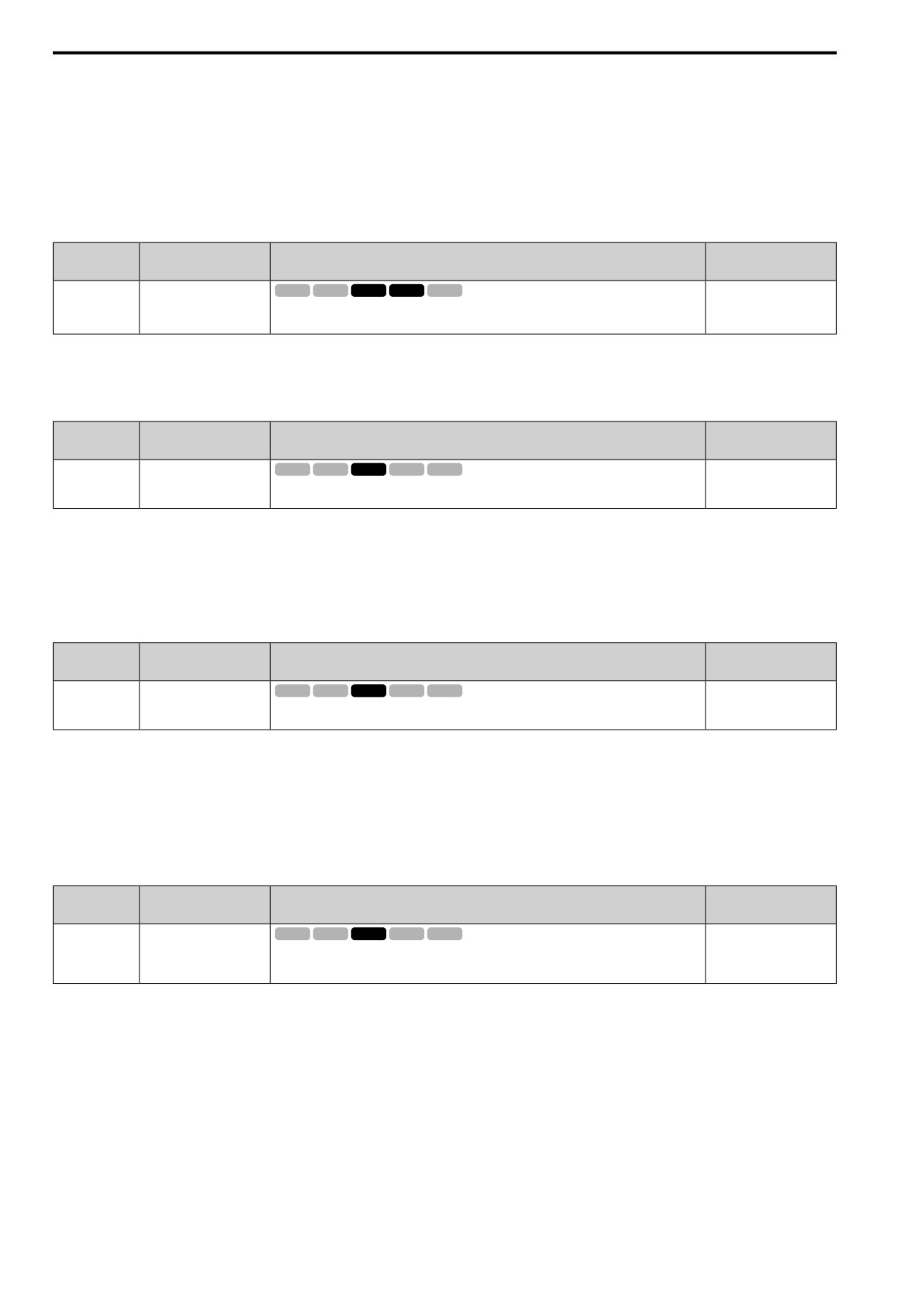
12.9 n: SPECIAL
Note:
• Set n8-35 = 2 [InitRotorPos Selection = HiFreq Injection] or n8-57 = 1 [High-Freq Injection = Enabled] to enable this parameter.
• Set n8-41 > 0.0 for IPM motors.
Configure the setting as follows.
• Decrease the setting in units of 0.5 if an oscillation or hunting occurs.
• Increase the setting in units of 0.5 if tracking related to load changes is required.
■ n8-42: HFI PoleDet iTime
No.
Default
Name
Description
(Hex.)
(Range)
HFI PoleDet iTime
V/f
OLV OLV/PM AOLV/PM EZOLV
n8-42
0.10 s
(0569)
Sets the integral time constant for the high frequency injection speed estimation. Usually it is not
(0.00 - 9.99 s)
necessary to change this setting.
Expert
Note:
Set n8-35 = 2 [InitRotorPos Selection = HiFreq Injection] or n8-57 = 1 [High-Freq Injection = Enabled] to enable this parameter.
■ n8-45: SpdFbck Det.Gain
No.
Default
Name
Description
(Hex.)
(Range)
SpdFbck Det.Gain
V/f
OLV OLV/PM AOLV/PM EZOLV
n8-45
0.80
(0538)
Sets the internal speed feedback detection reduction unit gain as a magnification value. Usually it
(0.00
- 10.00)
is not necessary to change this setting.
Adjust this parameter in these conditions:
• If vibration or hunting occur, increase the setting value in 0.05 unit increments.
• If the responsiveness of torque and speed is unsatisfactory, decrease the setting value 0.05 unit increments and
examine the response.
■ n8-47: Pull-In Comp.Time Constant
No.
Default
Name
Description
(Hex.)
(Range)
Pull-In Comp.Time
V/f
OLV OLV/PM AOLV/PM EZOLV
n8-47
5.0 s
Constant
(053A)
Sets the time constant the drive uses to align the pull-in current reference value with the actual
(0.0 - 100.0 s)
current value. Usually it is not necessary to change this setting.
Adjust this parameter in these conditions:
• If the time for the reference value of the pull-in current to align with the target value is too long, increase the
setting value.
• If vibration or hunting occur, decrease the setting value in 0.2 unit increments.
• If the motor stalls during run at constant speed, decrease the setting value in 0.2 unit increments.
■ n8-48: Pull-In Current (for PM Motors)
No.
Default
Name
Description
(Hex.)
(Range)
Pull-In Current (for PM
V/f
OLV OLV/PM AOLV/PM EZOLV
n8-48
30%
Motors)
(053B)
On the basis that parameter E5-03 [PM Mot Rated Current (FLA)] is the 100% value, this
(0 - 200%)
parameter sets the d-axis current that flows to the motor during run at constant speed as a
RUN
percentage.
Adjust in the following situations.
• Slightly reduce this value if there is too much current when driving a light load at a constant speed.
• Increase the setting value in steps of 5% when hunting or vibration occurs during run at constant speed.
• Increase the setting value in steps of 5% if the motor stalls during run at constant speed.
688
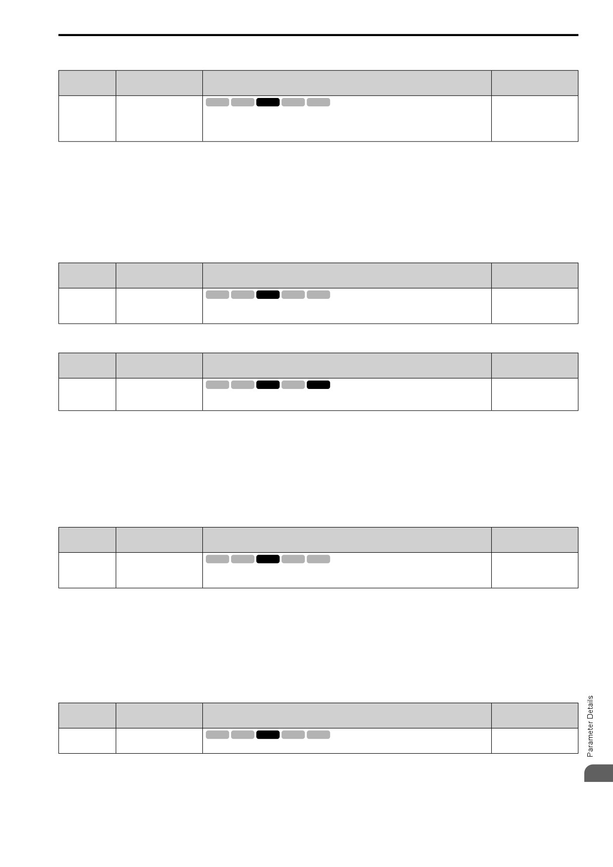
12.9 n: SPECIAL
■ n8-49: Heavy Load Id Current
No.
Default
Name
Description
(Hex.)
(Range)
Heavy Load Id Current
V/f
OLV OLV/PM AOLV/PM EZOLV
n8-49
Determined by E5-01
(053C)
Sets the d-axis current to that the drive will supply to the motor to run it at a constant speed with a
(-200.0 - +200.0%)
heavy load. Considers E5-03 [PM Mot Rated Current (FLA)] to be 100%. Usually it is not
RUN
necessary to change this setting.
Expert
When you use an IPM motor, you can use the reluctance torque of the motor to make the motor more efficient and
help conserve energy.
When you operate an SPN motor, set this parameter to 0.
Adjust in the following situations.
• If the load is large and motor rotation is not stable, decrease the setting value.
• When you change E5: PM MOTOR SETTINGS, set n8-49 = 0, then adjust this parameter.
■ n8-50: Medium Load Iq Level (High)
No.
Default
Name
Description
(Hex.)
(Range)
Medium Load Iq Level
V/f
OLV OLV/PM AOLV/PM EZOLV
n8-50
80%
(High)
(053D)
Sets the load current level at which heavy load control starts where E5-03 [PM Mot Rated Current
(50 - 255)
(FLA)] is 100%. Usually it is not necessary to change this setting.
Expert
■ n8-51: Ac/Dec Pull-In Current
No.
Default
Name
Description
(Hex.)
(Range)
Ac/Dec Pull-In Current
V/f
OLV OLV/PM AOLV/PM EZOLV
n8-51
Determined by A1-02
(053E)
Sets the pull-in current allowed to flow during acceleration/deceleration as a percentage of the
(0 - 200%)
motor rated current.
Adjust in the following situations.
• When the motor does not smoothly because of large loads, increase the setting value in 5% increments.
• If too much current flows during acceleration, decrease the setting value.
Note:
When A1-02 = 8 [Control Method = EZ Vector], this parameter will always be in effect for speed ranges less than n7-10 [Pull-in
SwitchSpeed].
■ n8-54: Volt-Err Compensation Time
No.
Default
Name
Description
(Hex.)
(Range)
Volt-Err Compensation
V/f
OLV OLV/PM AOLV/PM EZOLV
n8-54
1.00 s
Time
(056D)
Sets the time constant that the drive uses when adjusting for voltage errors.
(0.00 - 10.00 s)
Expert
Adjust this parameter in these conditions:
• If oscillation occurs at the time of start up, increase the setting value.
• If hunting occurs when operating at low speed, increase the setting value.
• If fast changes in the load cause hunting, increase the setting value in 0.1-unit increments. If you cannot stop
hunting, set n8-51 [Ac/Dec Pull-In Current] to 0% and set n8-54 to 0.00 s, and disable compensation for voltage
errors.
■ n8-55: Load Inertia
No.
Default
Name
Description
(Hex.)
(Range)
Load Inertia
V/f
OLV OLV/PM AOLV/PM EZOLV
n8-55
1
(056E)
Sets the ratio between motor inertia and machine inertia.
(1 - 4)
Adjust in the following situations.
12
• If torque and speed response is unsatisfactory, gradually increase the setting.
• If the motor does not run smoothly, gradually increase the setting.
689
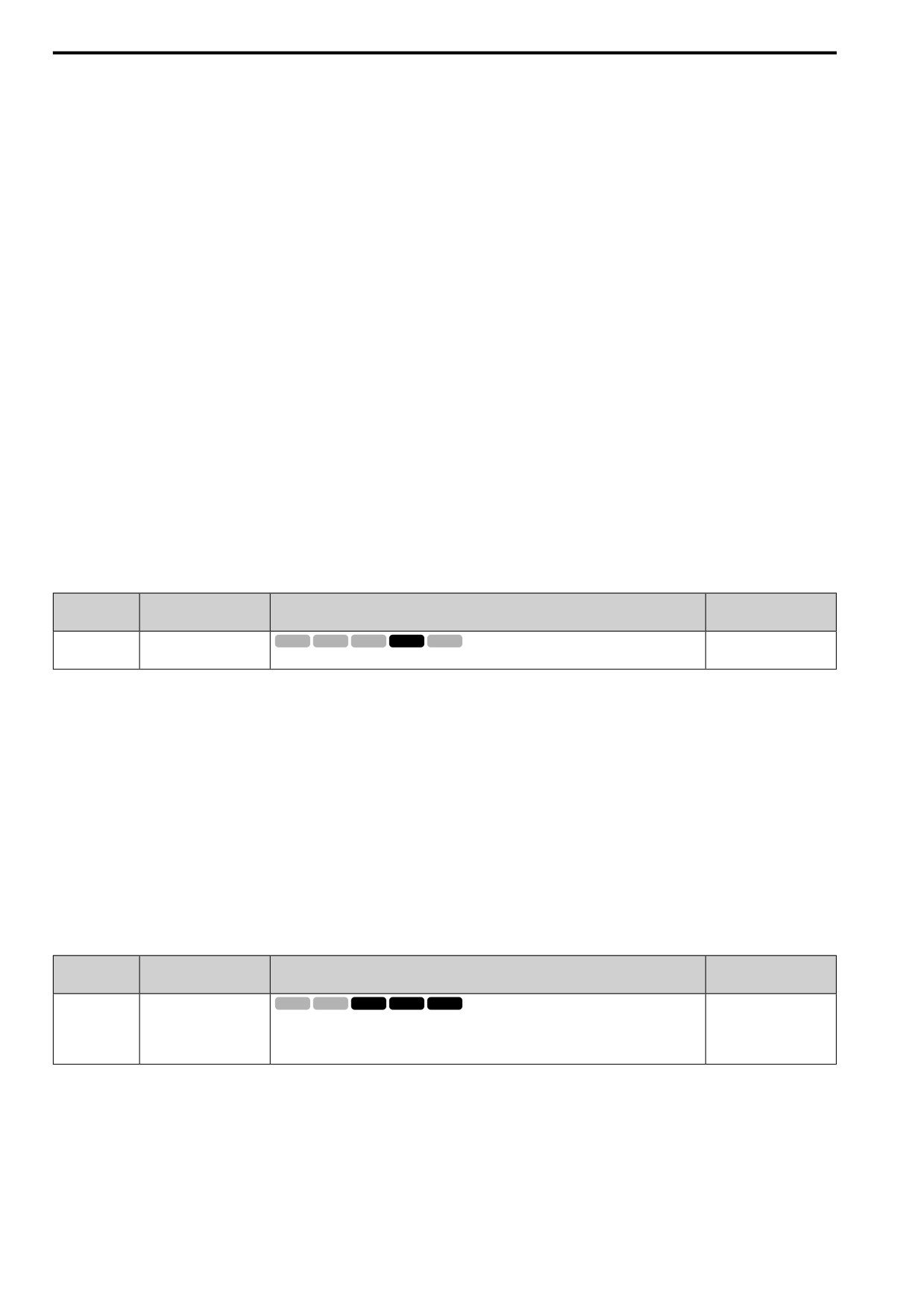
12.9 n: SPECIAL
• If the motor stalls during run at constant speed, gradually increase the setting.
• If there is vibration or hunting, decrease the setting.
Note:
• If the value is set too low, the drive will detect STPo [Motor Step-Out Detected].
• If you use one motor or more than motor at low inertia and the value is too high, there can be vibration in the motor.
1 : <1:10
Use this setting in these conditions:
• The ratio between the motor inertia and machine inertia is less than 1:10
• There are large current ripples
2 : 1:10-1:30
Use this setting in these conditions:
• The ratio between the motor inertia and machine inertia is approximately 1:10 to 1:30
• Parameter n8-55 = 1 and the drive detects STPo because of an impact load or sudden acceleration/deceleration.
3 : 1:30-1:50
Use this setting in these conditions:
• The ratio between the motor inertia and machine inertia is approximately 1:30 to 1:50
• Parameter n8-55 = 2 and the drive detects STPo because of an impact load or sudden acceleration/deceleration.
4 : >1:50
Adjust in the following situations.
• The ratio between the motor inertia and machine inertia is more than 1:50
• Parameter n8-55 = 3 and the drive detects STPo because of an impact load or sudden acceleration/deceleration.
■ n8-57: High-Freq Injection
No.
Default
Name
Description
(Hex.)
(Range)
High-Freq Injection
V/f
OLV OLV/PM AOLV/PM EZOLV
n8-57
0
(0574)
Sets the function that detects motor speed with high frequency injection.
(0, 1)
Note:
• When you set n8-57 = 1, doHigh Frequency Injection Auto-Tuning.
• When there is high frequency injection, the motor will make an excitation sound.
• When you use Zero Speed Control, set E1-09 [Min Output Frequency] = 0.0.
0 : Disabled
Use this setting with SPM motors. The speed control range is approximately 1:20.
When n8-57 = 0, you cannot set E1-09 [Min Output Frequency] ≤ 1/20 of the value of E1-06 [Base Frequency].
1 : Enabled
The speed control range changes to 1:100 to give sufficient speed detection at low speeds.
Note:
It is not available with an SPM motor.
■ n8-62: Output Volt Limit Level
No.
Default
Name
Description
(Hex.)
(Range)
Output Volt Limit Level
V/f
OLV OLV/PM AOLV/PM EZOLV
n8-62
200 V Class: 200.0 V, 400
V: 400.0 V
(057D)
Sets the output voltage limit to prevent saturation of the output voltage. Usually it is not necessary
to change this parameter.
(200 V Class: 0.0 to 230.0
Expert
V, 400 V Class: 0.0 to 460.0
V)
Set this parameter lower than the input power supply voltage.
690
12.9 n: SPECIAL
■ n8-63: Output Voltage Limit P Gain
No.
Default
Name
Description
(Hex.)
(Range)
Output Voltage Limit P
V/f
OLV OLV/PM AOLV/PM EZOLV
n8-63
1.00
Gain
(057E)
Sets the proportional gain for output voltage control. Usually it is not necessary to change this
(0.00
- 100.00)
setting.
Expert
■ n8-65: SpdFbk Gain@OV Suppression
No.
Default
Name
Description
(Hex.)
(Range)
SpdFbk Gain@OV
V/f
OLV OLV/PM AOLV/PM EZOLV
n8-65
1.50
Suppression
(065C)
Sets the gain of internal speed feedback detection suppression while the overvoltage suppression
(0.00
- 10.00)
function is operating as a magnification value. Usually it is not necessary to change this
Expert
parameter.
Adjust this parameter in these conditions:
• If there is resonance or hunting when you use the overvoltage suppression function, increase the setting value.
• If motor response is low when you use the overvoltage suppression function, decrease the setting value in 0.05-
unit increments.
■ n8-69: Spd Obs. P Gain Control
No.
Default
Name
Description
(Hex.)
(Range)
Spd Obs. P Gain Control
V/f
OLV OLV/PM AOLV/PM EZOLV
n8-69
1.00
(065D)
Usually it is not necessary to change this setting. Sets the Proportional gain that the drive uses for
(0.00
- 20.00)
speed estimation.
Expert
■ n8-72: Spd Obs. Method Selection
No.
Default
Name
Description
(Hex.)
(Range)
Spd Obs. Method Selection
V/f
OLV OLV/PM AOLV/PM EZOLV
n8-72
2
(0655)
Selects the speed estimation method. Usually it is not necessary to change this setting.
(1, 2)
Expert
1 : Method 1
2 : Method 2
■ n8-74: Light Load Iq Level
No.
Default
Name
Description
(Hex.)
(Range)
Light Load Iq Level
V/f
OLV OLV/PM AOLV/PM EZOLV
n8-74
30%
(05C3)
Set n8-48 [Pull-In Current (for PM Motors)] to the percentage of load current (q-axis current)
(0 - 255%)
that you will apply, where E5-03 [PM Mot Rated Current (FLA)] = a setting value of 100%.
Expert
Note:
• If n8-74 > n8-75 [Mid Load Iq Level (Low)], the drive will detect oPE08 [Parameter Selection Error].
• The change is linear between n8-74 and n8-75 and the level of the pull-in current from n8-48 to n8-78 [Mid Load Id Current].
■ n8-75: Mid Load Iq Level (Low)
No.
Default
Name
Description
(Hex.)
(Range)
Mid Load Iq Level (Low)
V/f
OLV OLV/PM AOLV/PM EZOLV
n8-75
50%
(05C4)
Set n8-78 [Mid Load Id Current] to the percentage of load current (q-axis current) that you will
(0 - 255%)
apply, where E5-03 [PM Mot Rated Current (FLA)] = a setting value of 100%.
Expert
Note:
• If n8-74 [Light Load Iq Level] > n8-75, the drive will detect oPE08 [Parameter Selection Error].
• The change is linear between n8-74 and n8-75 and the level of the pull-in current from n8-48 to n8-78 [Mid Load Id Current].
12
691
12.9 n: SPECIAL
■ n8-76: Id Switching Filter Time
No.
Default
Name
Description
(Hex.)
(Range)
n8-76
Id Switching Filter Time
V/f
OLV OLV/PM AOLV/PM EZOLV
200 ms
(05CD)
Sets the filter time constant for the d-axis current reference. Usually it is not necessary to change
(0 - 5000)
this setting.
Expert
■ n8-77: Hvy Load Iq Level
No.
Default
Name
Description
(Hex.)
(Range)
Hvy Load Iq Level
V/f
OLV OLV/PM AOLV/PM EZOLV
n8-77
90%
(05CE)
Set n8-49 [Heavy Load Id Current] to the percentage of load current (q-axis current) that you will
(0 - 255%)
apply, where E5-03 [PM Mot Rated Current (FLA)] = a setting value of 100%.
Expert
Note:
The change is linear between n8-75 [Mid Load Iq Level (Low)] and n8-77 and the level of the pull-in current from n8-78 [Mid Load Id
Current] to n8-49 [Heavy Load Id Current].
■ n8-78: Mid Load Id Current
No.
Default
Name
Description
(Hex.)
(Range)
Mid Load Id Current
V/f
OLV OLV/PM AOLV/PM EZOLV
n8-78
0%
(05F4)
Sets the level of the pull-in current as a percentage, where E5-03 [PM Mot Rated Current (FLA)]
(0 - 255%)
= 100%.
RUN
Expert
■ n8-79: Pull-In Curr@Deceleration
No.
Default
Name
Description
(Hex.)
(Range)
Pull-In Curr@Deceleration
V/f
OLV OLV/PM AOLV/PM EZOLV
n8-79
50%
(05FE)
Sets the pull-in current that can flow during deceleration as a percentage of the E5-03 [PM Mot
(0 - 200%)
Rated Current (FLA)].
If overcurrent occurs during deceleration, slowly decrease the setting in 5% increments.
Note:
When n8-79 = 0, the drive will use the value set in n8-51 [Ac/Dec Pull-In Current].
■ n8-84: Polarity Det Current
No.
Default
Name
Description
(Hex.)
(Range)
Polarity Det Current
V/f
OLV OLV/PM AOLV/PM EZOLV
n8-84
100%
(02D3)
Sets the current that the drive uses to estimate the initial motor magnetic pole as a percentage
(0 - 150%)
where E5-03 [PM Mot Rated Current (FLA)] = 100%.
Expert
WARNING! Sudden Movement Hazard. Make sure that the polarity is correct before you send a Run command. If the drive
incorrectly detects the polarity, the drive can rotate in the direction opposite of the Run command and cause serious injury or
death.
When you use a Yaskawa motor, check the motor nameplate for an “Si” value and set this parameter ≥ "Si × 2".
Consult the motor manufacturer for information about maximum setting values.
Find the Polarity of Magnetic Poles
When you start operation, the drive estimates the magnetic poles and finds the polarity of the magnetic poles.
Use U6-57 [n8-84: PoleDis IdDifVal] to make sure that the magnetic pole estimate was correct.
When you do High Frequency Injection Auto-Tuning, the drive automatically sets n8-84.
■ n8-87: O/P VoltLim Method
No.
Default
Name
Description
(Hex.)
(Range)
O/P VoltLim Method
V/f
OLV OLV/PM AOLV/PM EZOLV
n8-87
0
(02BC)
Sets the method of output voltage limit. If there is vibration in the constant output range, set
(0, 1)
Feedforward Method. Usually it is not necessary to change this setting.
692
12.9
n: SPECIAL
0 : Feedback Method
1 : Feedforward Method
■ n8-88: VoutLimSw Level
No.
Default
Name
Description
(Hex.)
(Range)
VoutLimSw Level
V/f
OLV OLV/PM AOLV/PM EZOLV
n8-88
400%
(02BD)
Sets the current level at which output voltage limit sequence selection occurs as a percentage
(0 - 400%)
where the motor rated current is 100%. Normally there is no need to change this setting.
■ n8-89: VoutLimSwHysteresis
No.
Default
Name
Description
(Hex.)
(Range)
VoutLimSwHysteresis
V/f
OLV OLV/PM AOLV/PM EZOLV
n8-89
3%
(02BE)
Sets the hysteresis width of the current level at which output voltage limit sequence selection
(0 - 400%)
occurs as a percentage where the motor rated current is 100%. Normally there is no need to
change this setting.
■ n8-90: VoutLimSwSpeed
No.
Default
Name
Description
(Hex.)
(Range)
VoutLimSwSpeed
V/f
OLV OLV/PM AOLV/PM EZOLV
n8-90
200%
(02BF)
Sets the speed level at which output voltage limit sequence selection occurs as a percentage where
(0 - 200%)
the maximum output frequency is 100%. Usually it is not necessary to change this setting.
■ n8-91: VoutLim Id Limit
No.
Default
Name
Description
(Hex.)
(Range)
VoutLim Id Limit
V/f
OLV OLV/PM AOLV/PM EZOLV
n8-91
-50%
(02F7)
Sets the limit value of feedback output voltage limit Id operation. Enabled when n8-87 = 0 [O/P
(-200 - 0%)
VoltLim Method = Speed Feedback Form]. Usually it is not necessary to change this setting.
■ n8-94: FluxPos Est.Method
No.
Default
Name
Description
(Hex.)
(Range)
FluxPos Est.Method
V/f
OLV OLV/PM AOLV/PM EZOLV
n8-94
2
(012D)
Sets the criteria that the drive uses to find changes in speed or load. Usually it is not necessary to
(1, 2)
change this setting.
Expert
1 : Softstarter
2 : Speed Feedback
Set n8-57 = 1 [High-Freq Injection = Enabled] to enable this parameter. Increases the stability when the speed or
load suddenly change, for example with rapid acceleration/deceleration or impact loads.
■ n8-95: FluxPos Est.Filter Time
No.
Default
Name
Description
(Hex.)
(Range)
FluxPos Est.Filter Time
V/f
OLV OLV/PM AOLV/PM EZOLV
n8-95
30 ms
(012E)
Sets the time constant of the filter used for the recognition criteria value for speed and load
(0 - 100 ms)
changes. Usually it is not necessary to change this setting.
Expert
Note:
Enabled when n8-94 = 2 [FluxPos Est.Method = Speed Feedback].
◆ nA: PM MOTOR CONTROL TUNING
nA parameters make adjustments for controlling PM motors.
12
693
12.9 n: SPECIAL
■ nA-01: Obs Calc Gain 3
No.
Default
Name
Description
(Hex.)
(Range)
nA-01
Obs Calc Gain 3
V/f
OLV OLV/PM AOLV/PM EZOLV
30.0
(3129)
Sets the gain for speed estimation. Usually it is not necessary to change this setting.
(0.0
- 1000.0)
Expert
694
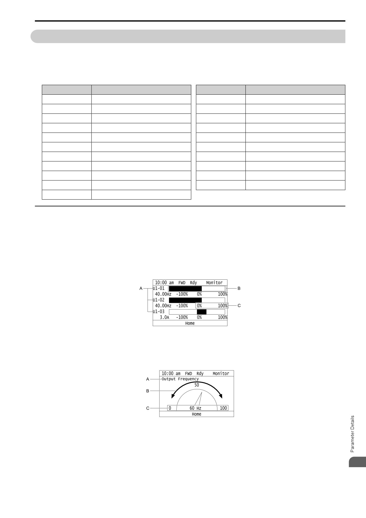
12.10
o: KEYPAD
12.10
o: KEYPAD
o parameters set keypad functions.
Note:
You cannot use the optional LED keypad to set these parameters.
Table 12.55 Parameters You Cannot Set with the LED Keypad
No.
Name
No.
Name
o1-05
LCD Contrast Adjustment
o3-04
Select Backup/Restore Location
o1-24 to o1-35
Custom Monitor 1 to 12
o3-05
Select Items to Backup/Restore
o1-36
LCD Backlight Brightness
o3-06
Auto Parameter Backup Selection
o1-37
LCD Backlight ON/OFF Selection
o3-07
Auto Parameter Backup Interval
o1-38
LCD Backlight Off-Delay
o4-22
Time Format
o1-39
Show Initial Setup Screen
o4-23
Date Format
o1-40
Home Screen Display Selection
o4-24
bAT Detection Selection
o1-41 to o1-46
1st to 3rd Monitor Area Selections/Settings
o5-01
Log Start/Stop Selection
o1-47 to o1-51
Trend Plot 1 or 2 Scale Settings
o5-02
Log Sampling Interval
o1-55 to o1-56
Analog Gauge Area Selection/Setting
o5-03 to o5-12
Log Monitor Data 1 to 10
o2-27
bCE Detection Selection
◆ o1: KEYPAD DISPLAY
o1 parameters select the parameters shown on the initial keypad screen and to configure the parameter setting
units and display units. These parameters also adjust the backlight and contrast of the LCD display.
■ Home Screen Display Format
o1-40 [Home Screen Selection Mode] changes the display of the monitor shown on the Home screen. You can
show numerical values or one of these three displays on the Home screen monitor:
Bar Graph Display
A - Select Ux-xx [Monitors] with o1-24, o1-25, and
C - Select display ranges with o1-42, o1-44, and o1-
o1-26.
46.
B - Configure display regions with o1-41, o1-43,
and o1-45.
Analog Gauge Display
A - Select Ux-xx [Monitors] with o1-24.
C - Select display ranges with o1-55.
B - Configure display regions with o1-56.
12
695
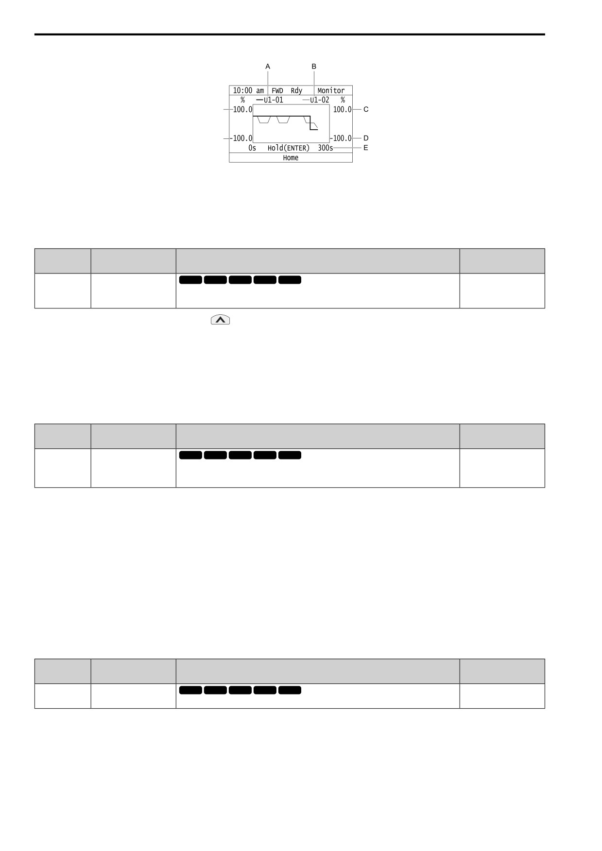
12.10 o: KEYPAD
Trend Plot Display
G
F
A - Select Ux-xx [Monitors] (Monitor 1) with o1-24.
E - Set the time scale with o1-51
B - Select Ux-xx [Monitors] (Monitor 2) with o1-25.
F - Set the minimum value of Monitor 1 with o1-47
C - Set the maximum value of Monitor 2 with o1-50
G - Set the maximum value of Monitor 1 with o1-48
D - Set the minimum value of Monitor 2 with o1-49
■ o1-01: User Monitor Selection
No.
Default
Name
Description
(Hex.)
(Range)
User Monitor Selection
V/f
OLV OLV/PM AOLV/PM EZOLV
o1-01
106
(0500)
Sets the U: MONITORS for the Drive Mode. This parameter is only available when you use an
(104 - 855)
LED keypad.
RUN
When the drive is in Drive Mode, push
on the keypad to cycle through this data: frequency reference →
rotational direction → output frequency → output current → o1-01 selection.
Set the x-xx part of Ux-xx that is shown in the fifth position in Drive Mode. For example, to show U1-05 [Motor
Speed], set o1-01 = 105.
Note:
The monitors that you can select are different for different control methods.
■ o1-02: Mon.Sel@Power-Up
No.
Default
Name
Description
(Hex.)
(Range)
Mon.Sel@Power-Up
V/f
OLV OLV/PM AOLV/PM EZOLV
o1-02
1
(0501)
Sets the monitor item that the keypad screen shows after energizing the drive. Refer to “U:
(1 - 5)
MONITORS” for information about the monitor items that the keypad screen can show. This
RUN
parameter is only available when you use an LED keypad.
1 : FreqReference (U1-01)
2 : Direction
3 : OutFrequency (U1-02)
4 : OutCurrent (U1-03)
5 : User Monitor (o1-01)
Shows the monitor item selected in o1-01 [User Monitor Selection].
■ o1-03: FrqDisplay Unit Selection
No.
Default
Name
Description
(Hex.)
(Setting Range)
FrqDisplay Unit Selection
V/f
OLV OLV/PM AOLV/PM EZOLV
o1-03
Determined by A1-02
(0502)
Sets the display units for the frequency reference and output frequency.
(0 - 3)
696
12.10 o: KEYPAD
Note:
• Select the setting unit of these parameters:
-d1-01 to d1-17 [Reference 1 to Jog Reference]
-U1-01 [Frequency Reference]
-U1-02 [Output Frequency]
-U1-05 [Motor Speed]
-U1-16 [SFS Output Frequency]
-U4-14 [PeakHold OutFreq]
• For monitor 2, the setting value is always 0 [0.01 Hz].
0 : 0.01 Hz
1 : 0.01% (100%=E1-04)
The maximum output frequency is 100%.
2 : rpm
The drive uses the maximum output frequency and number of motor poles calculate this value automatically.
Note:
When you set o1-03=2[r/min], make sure that you set the number of motor poles in these parameters:
• E2-04 [Motor Pole Count]
• E4-04 [M2 Pole Count]
• E5-04 [PM Mot Pole Count]
• E9-08 [Motor Pole Count]
3 : User-selected units
Uses o1-10 and o1-11 to set the unit of measure. The value of parameter o1-10 is the value when you remove the
decimal point from the maximum output frequency. Parameter o1-11 is to the number of digits after the decimal
point in the maximum output frequency.
To display a maximum output frequency of 100.00, set parameters to these values:
• o1-10 = 10000
• o1-11 = 2 [FrqDisplay Decimal Places = (XXX.XX) 2 Decimal Places]
■ o1-04: V/f Pattern Unit for Display
No.
Default
Name
Description
(Hex.)
(Range)
V/f Pattern Unit for Display
V/f
OLV OLV/PM AOLV/PM EZOLV
o1-04
Determined by A1-02
(0503)
Sets the setting unit for parameters that set the V/f pattern frequency.
(0, 1)
Note:
• Select the units for these parameters:
-E1-04 [Max Output Frequency]
-E1-06 [Base Frequency]
-E1-07 [Mid A Frequency]
-E1-09 [Min Output Frequency]
-E1-11 [Mid B Frequency]
-E9-02 [Maximum Speed]
-E9-04 [Base Frequency]
• For motor 2, the settings are always 0 [Hz].
0 : Hz
1 : rpm
When you set o1-04 = 1 [rpm], you must also use these parameters to set the motor pole count:
• E2-04 [Motor Pole Count]
• E5-04 [PM Mot Pole Count]
• E9-08 [Motor Pole Count]
12
697
12.10 o: KEYPAD
■ o1-05: LCD Contrast Adjustment
No.
Default
Name
Description
(Hex.)
(Range)
LCD Contrast Adjustment
V/f
OLV OLV/PM AOLV/PM EZOLV
o1-05
5
(0504)
Sets the contrast of the LCD display on the keypad.
(0 - 10)
RUN
When you decrease the setting value, the contrast of the LCD display decreases. When you increase the setting
value, the contrast increases.
■ o1-10: FrqDisplay Max Value
No.
Default
Name
Description
(Hex.)
(Range)
FrqDisplay Max Value
V/f
OLV OLV/PM AOLV/PM EZOLV
o1-10
Determined by o1-03
(0520)
Sets the value that the drive shows as the maximum output frequency.
(1 - 60000)
To display a maximum output frequency of 100.00, set parameters to these values:
• o1-10 = 10000
• o1-11 = 2 [FrqDisplay Decimal Places = (XXX.XX) 2 Decimal Places]
Note:
Set o1-03 = 3 [FrqDisplay Unit Selection = User-selected units] before you set o1-10 and o1-11.
■ o1-11: FrqDisplay Decimal Places
No.
Default
Name
Description
(Hex.)
(Range)
FrqDisplay Decimal Places
V/f
OLV OLV/PM AOLV/PM EZOLV
o1-11
Determined by o1-03
(0521)
Sets the number of decimal places for frequency reference and monitor values.
(0 - 3)
0 : (XXXXX) No Decimal Places
1 : (XXXX.X) 1 Decimal Place
2 : (XXX.XX) 2 Decimal Places
3 : (XX.XXX) 3 Decimal Places
Note:
Set o1-03 = 3 [FrqDisplay Unit Selection = User-selected units] before you set o1-10 [FrqDisplay Max Value] and o1-11.
■ o1-24 to o1-35: Cust.Monitor 1 to 12
No.
Default
Name
Description
(Hex.)
(Range)
Cust.Monitor 1 to 12
V/f
OLV OLV/PM AOLV/PM EZOLV
o1-24 to o1-35:
o1-24: 101
(11AD - 11B8)
Sets a maximum of 12 monitors as user monitors. This parameter is only available when using an
o1-25: 102
LCD keypad.
RUN
o1-26: 103
o1-27 to o1-35: 0
(0, 101 - 999)
These parameters save the monitor items selected by the LCD keypad [Custom Monitor].
Note:
• You can show a maximum of three selected monitors on one LCD keypad screen.
-When you select only one monitor, the text size of this monitor increases. For example, when o1-25 to o1-35 = 0, the text size of the
monitor saved in o1-24 increases.
-When you select two monitors, the text size of these monitors increase.
-When you select four or more monitors, the fourth monitor and all additional monitors are shown on the next screens.
• Monitors selected with o1-24 to o1-26 can be displayed as a bar graph, analog gauge, or trend plot.
-Bar graph display: 3 monitors maximum
Select with o1-24, o1-25, and o1-26.
-Analog gauge display: 1 monitor
Select with o1-24.
-Trend plot display: 2 monitors
Select with o1-24 and o1-25.
• You can only set parameters o1-24 to o1-26 with analog output monitors.
• You can set all monitors to parameters o1-27 to o1-35.
698
12.10 o: KEYPAD
■ o1-36: LCD Backlight Brightness
No.
Default
Name
Description
(Hex.)
(Range)
LCD Backlight Brightness
V/f
OLV OLV/PM AOLV/PM EZOLV
o1-36
3
(11B9)
Sets the intensity of the LCD keypad backlight.
(1 - 5)
RUN
When you decrease the setting value, the intensity of the backlight decreases.
■ o1-37: LCD Blight ON/OFF Selection
No.
Default
Name
Description
(Hex.)
(Range)
LCD Blight ON/OFF
V/f
OLV OLV/PM AOLV/PM EZOLV
o1-37
1
Selection
(11BA)
Sets the automatic shut off function for the LCD backlight.
(0, 1)
RUN
Note:
Use o1-36 [LCD Backlight Brightness] to adjust the intensity of the LCD backlight.
0 : OFF
1 : ON
Enables the automatic shut off function. The backlight will automatically turn off after the time set in o1-38 [LCD
Blight Off-Delay] is expired.
Note:
When o1-37 = 1 and the backlight is OFF, the keys other than
are disabled.
When the backlight is off, push a key on the keypad to temporarily turn the backlight on. Push any key to start keypad operation, Push
to turn the backlight on, then push
again to enter a Run command to the drive.
■ o1-38: LCD Blight Off-Delay
No.
Default
Name
Description
(Hex.)
(Range)
LCD Blight Off-Delay
V/f
OLV OLV/PM AOLV/PM EZOLV
o1-38
60 s
(11BB)
Sets the time until the LCD backlight automatically turns off.
(10 - 300 s)
RUN
When o1-37 = 1 [LCD Blight ON/OFF Selection = ON], the backlight will automatically turn off after the time
set in o1-38 expires.
When the backlight is off, push a key on the keypad to temporarily turn the backlight on. After the backlight turns
on, it will turn off automatically after the time set in o1-38 is expired.
■ o1-39: Show Init Screen
No.
Default
Name
Description
(Hex.)
(Range)
Show Init Screen
V/f
OLV OLV/PM AOLV/PM EZOLV
o1-39
1
(11BC)
Sets the function to show the LCD keypad initial setup screen each time the drive is energized.
(0, 1)
This parameter is only available when using an LCD keypad.
RUN
The initial setup screen shows a menu where you can select the display language, set the date, time, and other
basic settings. When you set this parameter to 0, the drive will not show this screen each time you energize the
drive.
0 : No
The drive will not show the initial setup display screen each time you energize the drive. The drive will show the
Home screen.
1 : Yes
When you input the Run command before you energize the drive or when the you turn on the Run command while
the drive shows the initial setup screen, the drive will replace the initial setup screen with the Home screen.
12
699
12.10 o: KEYPAD
■ o1-40: Home Screen Selection Mode
No.
Default
Name
Description
(Hex.)
(Range)
Home Screen Selection
V/f
OLV OLV/PM AOLV/PM EZOLV
o1-40
0
Mode
(11BD)
Sets the monitor display mode for the Home screen. This parameter is only available when using
(0, 10 - 12)
an LCD keypad.
RUN
0 : Monitors
10 : Bar Graph
11 : Analog Gauge
12 : Trend Plot
■ o1-41: 1stMon Area Selection
No.
Default
Name
Description
(Hex.)
(Range)
1stMon Area Selection
V/f
OLV OLV/PM AOLV/PM EZOLV
o1-41
0
(11C1)
Sets the horizontal range used to display the monitor set in o1-24 [Cust.Monitor 1] as a bar graph.
(0, 1)
This parameter is only available when using an LCD keypad.
RUN
0 : +/- Area (- o1-42 - o1-42 )
1 : + Area (0 - o1-42 )
■ o1-42: 1stMon Area Setting
No.
Default
Name
Description
(Hex.)
(Range)
1stMon Area Setting
V/f
OLV OLV/PM AOLV/PM EZOLV
o1-42
100.0%
(11C2)
Sets the horizontal axis value used to display the monitor set in o1-24 [Cust.Monitor 1] as a bar
(0.0
- 100.0%)
graph. This parameter is only available when using an LCD keypad.
RUN
■ o1-43: 2ndMon Area Selection
No.
Default
Name
Description
(Hex.)
(Range)
2ndMon Area Selection
V/f
OLV OLV/PM AOLV/PM EZOLV
o1-43
0
(11C3)
Selects the horizontal range used to display the monitor set in o1-25 [Cust.Monitor 2] as a bar
(0, 1)
graph. This parameter is only available when using an LCD keypad.
RUN
0 : + - Area (- o1-44 - o1-44)
1 : + Area (0 - o1-44)
■ o1-44: 2ndMon Area Setting
No.
Default
Name
Description
(Hex.)
(Range)
2ndMon Area Setting
V/f
OLV OLV/PM AOLV/PM EZOLV
o1-44
100.0%
(11C4)
Sets the horizontal axis value used to display the monitor set in o1-25 [Cust.Monitor 2] as a bar
(0.0
- 100.0%)
graph. This parameter is only available when using an LCD keypad.
RUN
■ o1-45: 3rdMon Area Selection
No.
Default
Name
Description
(Hex.)
(Range)
3rdMon Area Selection
V/f
OLV OLV/PM AOLV/PM EZOLV
o1-45
0
(11C5)
Sets the horizontal range used to display the monitor set in o1-26 [Cust.Monitor 3] as a bar graph.
(0, 1)
This parameter is only available when using an LCD keypad.
RUN
0 : + - Area (- o1-46 - o1-46)
1 : + Area (0 - o1-46 )
700
12.10 o: KEYPAD
■ o1-46:
3rdMon Area Setting
No.
Default
Name
Description
(Hex.)
(Range)
3rdMon Area Setting
V/f
OLV OLV/PM AOLV/PM EZOLV
o1-46
100.0%
(11C6)
Sets the horizontal axis value used to display the monitor set in o1-26 [Cust.Monitor 3] as a bar
(0.0
- 100.0%)
graph. This parameter is only available when using an LCD keypad.
RUN
■ o1-47: Trend Plot 1
Min Scale Value
No.
Default
Name
Description
(Hex.)
(Range)
Trend Plot 1 Min Scale
V/f
OLV OLV/PM AOLV/PM EZOLV
o1-47
-100.0%
Value
(11C7)
Sets the horizontal axis minimum value used to display the monitor set in o1-24 [Cust.Monitor 1]
(-300.0 - +300.0%)
as a trend plot. This parameter is only available when using an LCD keypad.
RUN
■ o1-48: Trend Plot 1
Max Scale Value
No.
Default
Name
Description
(Hex.)
(Range)
Trend Plot 1 Max Scale
V/f
OLV OLV/PM AOLV/PM EZOLV
o1-48
100.0%
Value
(11C8)
Sets the horizontal axis maximum value used to display the monitor set in o1-24 [Cust.Monitor 1]
(-300.0 - +300.0%)
as a trend plot. This parameter is only available when using an LCD keypad.
RUN
■ o1-49: Trend Plot 2
Min Scale Value
No.
Default
Name
Description
(Hex.)
(Range)
Trend Plot 2 Min Scale
V/f
OLV OLV/PM AOLV/PM EZOLV
o1-49
-100.0%
Value
(11C9)
Sets the horizontal axis minimum value used to display the monitor set in o1-25 [Cust.Monitor 2]
(-300.0 - +300.0%)
as a trend plot. This parameter is only available when using an LCD keypad.
RUN
■ o1-50: Trend Plot 2
Max Scale Value
No.
Default
Name
Description
(Hex.)
(Range)
Trend Plot 2 Max Scale
V/f
OLV OLV/PM AOLV/PM EZOLV
o1-50
100.0%
Value
(11CA)
Sets the horizontal axis maximum value used to display the monitor set in o1-25 [Cust.Monitor 2]
(-300.0 - +300.0%)
as a trend plot. This parameter is only available when using an LCD keypad.
RUN
■ o1-51: Trend Plot Time Scale Setting
No.
Default
Name
Description
(Hex.)
(Range)
Trend Plot Time Scale
V/f
OLV OLV/PM AOLV/PM EZOLV
o1-51
300 s
Setting
(11CB)
Sets the time scale (horizontal axis) to display the trend plot. When you change this setting, the
(1 - 3600 s)
drive automatically adjusts the data sampling time. This parameter is only available when using
RUN
an LCD keypad.
■ o1-55: AnGauge Area Selection
No.
Default
Name
Description
(Hex.)
(Range)
AnGauge Area Selection
V/f
OLV OLV/PM AOLV/PM EZOLV
o1-55
1
(11EE)
Sets the range used to display the monitor set in o1-24 [Custom Monitor 1] as an analog gauge.
(0, 1)
This parameter is only available when using an LCD keypad.
RUN
0 : + - Area (- o1-56 - o1-56 )
1 : + Area (0 - o1-56 )
■ o1-56: AnGauge Area Setting
No.
Default
Name
Description
(Hex.)
(Range)
AnGauge Area Setting
V/f
OLV OLV/PM AOLV/PM EZOLV
o1-56
100.0%
12
(11EF)
Sets the value used to display the monitor set in o1-24 [Cust.Monitor 1] as an analog meter. This
(0.0
- 100.0%)
parameter is only available when using an LCD keypad.
RUN
701
12.10 o: KEYPAD
■ o1-58: Mot Capacity Unit
No.
Default
Name
Description
(Hex.)
(Range)
Mot Capacity Unit
V/f
OLV OLV/PM AOLV/PM EZOLV
o1-58
0
(3125)
Sets the setting unit for parameters that set the motor rated power.
(0, 1)
The drive shows these parameter values in the set units:
• E2-11 [Motor Rated Power (kW)]
• E4-11 [M2 Rated Power (kW)]
• E5-02 [PM Mot Rated Power (kW)]
• E9-07 [Motor Rated Power (kW)]
• T1-02 [Motor Rated Power]
• T2-04 [PMMot Rated Power]
• T4-08 [Motor Rated Capacity]
0 : kW
Shows the motor output in kW units.
1 : HP
Shows the motor output in HP units.
◆ o2: KEYPAD OPERATION
■ o2-01: LO/RE Key Selection of Function
No.
Default
Name
Description
(Hex.)
(Range)
LO/RE Key Selection of
V/f
OLV OLV/PM AOLV/PM EZOLV
o2-01
1
Function
(0505)
(0, 1)
Sets the function that lets you use
to switch between LOCAL and REMOTE Modes.
0 : Disabled
You cannot use
to switch between LOCAL and REMOTE Modes.
1 : Enabled
You can use
to switch between LOCAL and REMOTE Modes when the drive is stopped. When LOCAL
Mode is selected,
on the keypad will come on.
WARNING! Sudden Movement Hazard. If you change the control source when b1-07 = 2 [LO/RE Run Selection = Accept RUN],
the drive can start suddenly. Before you change the control source, remove all personnel from the area around the drive, motor,
and load. Sudden starts can cause serious injury or death.
WARNING! Sudden Movement Hazard. Fully examine all mechanical and electrical connections before you change o2-01 [LO/
RE Key Selection of Function] or b1-07 [LO/RE Run Selection]. Sudden starts can cause serious injury or death. If b1-07 = 2
[LO/RE Run Selection = Accept RUN] and there is an active Run command when you switch from LOCAL to REMOTE Mode,
the drive can start suddenly.
Table 12.56 Function Settings with o2-01 and b1-07
Switching from LOCAL Mode to
Switching from REMOTE Mode to
Function Selection
LOCAL/REMOTE Run Selection
REMOTE Mode
LOCAL Mode
o2-01 = 0 [Disabled]
b1-07 = 1 [Cycle RUN]
The drive will not switch modes.
The drive will not switch modes.
b1-07 = 2 [Accept RUN]
o2-01 = 1 [Enabled]
b1-07 = 1 [Cycle RUN]
The drive will not start operating although
The drive cannot operate because the Run
the Run command is active. When you set
command is not enabled.
Run command to active again, the drive
will start to run.
b1-07 = 2 [Accept RUN]
When the Run command is active, the
The drive cannot operate because the Run
drive will start to run immediately when
command is not enabled.
the mode switches from LOCAL to
REMOTE.
702
12.10 o: KEYPAD
■ o2-02: STOP Key Selection of Function
No.
Default
Name
Description
(Hex.)
(Setting Range)
STOP Key Selection of
V/f
OLV OLV/PM AOLV/PM EZOLV
o2-02
1
Function
(0506)
(0, 1)
Sets the function to use
on the keypad to stop the drive when the Run command source
for the drive is REMOTE (external) and not assigned to the keypad.
0 : Disabled
1 : Enabled
stays enabled when the Run command source has not been assigned to the keypad.
To start the drive again after you push
to stop operation, turn the external Run command OFF and ON
again.
■ o2-03: UserPar Set Default Values
No.
Default
Name
Description
(Hex.)
(Range)
UserPar Set Default Values
V/f
OLV OLV/PM AOLV/PM EZOLV
o2-03
0
(0507)
Sets the function to keep the settings of changed parameters as user parameter defaults to use
(0 - 2)
during initialization.
When you set o2-03 = 1 [Set defaults], the drive saves changed parameter settings as user parameter setting
values in a part of the memory that is isolated from drive parameters.
When you set A1-03 = 1110 [Init Parameters = User / Solution Initialization] to initialize the drive, the drive
resets the internal parameter setting values to those user parameter setting values.
0 : No change
1 : Set defaults
Saves changed parameter setting values as user default settings.
Set o2-03 = 1 then push
to save the user parameter setting values. After the drive saves the setting value, o2-
03 automatically resets to 0.
2 : Clear all
Deletes all of the saved user parameter setting values.
Set o2-03 = 2 then push
to clear the user parameter setting values. The drive will automatically reset o2-03 to
0. If you delete the user parameter setting values, you cannot set A1-03 = 1110 to initialize parameters.
■ o2-04: Drive KVA Selection
No.
Default
Name
Description
(Hex.)
(Setting Range)
Drive KVA Selection
V/f
OLV OLV/PM AOLV/PM EZOLV
o2-04
Determined by the drive
(0508)
Sets the Drive Model code. Set this parameter after replacing the control board.
(-)
NOTICE: Set o2-04 [Drive KVA Selection] correctly. If you set this parameter incorrectly, it will decrease drive performance,
cause the protection function to operate incorrectly, and cause damage to the drive.
Note:
When the setting value of o2-04 changes, related parameter setting values also change. Refer to Defaults by Drive Model and Duty
Rating ND/HD on page 409 for more information.
These tables list the relation between o2-04 setting values and drive models.
o2-04 Setting
Drive Model
o2-04 Setting
Drive Model
30
B001
37
B018
31
B002
60
2001
32
B004
61
2002
33
B006
62
2004
12
34
B010
63
2006
35
B012
64
2008
703
12.10 o: KEYPAD
o2-04 Setting
Drive Model
o2-04 Setting
Drive Model
65
2010
99
4004
66
2012
6A
4005
67
2018
6B
4007
68
2021
6D
4009
91
2030
6E
4012
92
2042
6F
4018
93
2056
9A
4023
94
2070
9C
4031
95
2082
9D
4038
96
4001
9E
4044
97
4002
9F
4060
■ o2-05: LCD FreqRef Mode@Home Screen
No.
Default
Name
Description
(Hex.)
(Setting Range)
LCD FreqRef
V/f
OLV OLV/PM AOLV/PM EZOLV
o2-05
0
Mode@Home Screen
(0509)
(0, 1)
Sets the function that makes it necessary to push
to use the keypad to change the frequency
reference value while in Drive Mode.
0 : Disabled
You must push
to use the keypad to change the frequency reference value.
1 : Enabled
The frequency reference changes when you enter it with the keypad. This then changes the output frequency. It is
not necessary to push
. The drive keeps the frequency reference for 5 seconds after you use
and
on
the keypad to change the frequency reference value.
■ o2-06: Keypad Disconnect Detection
No.
Default
Name
Description
(Hex.)
(Range)
Keypad Disconnect
V/f
OLV OLV/PM AOLV/PM EZOLV
o2-06
0
Detection
(050A)
Sets the function that stops the drive if you disconnect the keypad connection cable from the drive
(0, 1)
or if you damage the cable while the keypad is the Run command source.
This parameter continues to operate if the keypad installed to the drive becomes disconnected.
This parameter is enabled in these conditions:
• When b1-02 = 0 [Run Comm. Sel 1 = Keypad] or b1-16 = 0 [Run Comm. Sel 2 = Keypad]
• In LOCAL Mode
0 : Disabled
The drive continues operation when it detects a keypad disconnection.
1 : Enabled
The drive stops operation, detects oPr [Keypad Connection Fault], and the motor coasts to stop when the drive
detects a keypad disconnection.
■ o2-07: Keypad Dir@Power-Up
No.
Default
Name
Description
(Hex.)
(Range)
Keypad Dir@Power-Up
V/f
OLV OLV/PM AOLV/PM EZOLV
o2-07
0
(0527)
Sets the direction of motor rotation when the drive is energized and the keypad is the Run
(0, 1)
command source.
This parameter is enabled in these conditions:
• When b1-02 = 0 [Run Comm. Sel 1 = Keypad] or b1-16 = 0 [Run Comm. Sel 2 = Keypad]
• In LOCAL Mode
704
12.10 o: KEYPAD
0 : Forward
1 : Reverse
■ o2-09: Region Code for Initialization
No.
Default
Name
Description
(Hex.)
(Range)
Region Code for
o2-09
-
-
Initialization
(050D)
■ o2-19: Parameter Write during Uv
No.
Default
Name
Description
(Hex.)
(Range)
Parameter Write during Uv
V/f
OLV OLV/PM AOLV/PM EZOLV
o2-19
0
(061F)
Lets you change parameters during Uv [Undervoltage].
( 0, 1 )
Expert
0 : Disable
1 : Enable
■ o2-23: Ext24V Off Warning Display
No.
Default
Name
Description
(Hex.)
(Setting Range)
Ext24V Off Warning
V/f
OLV OLV/PM AOLV/PM EZOLV
o2-23
0
Display
(11F8)
Sets the function to give a warning if the backup external 24 V power supply turns off when the
(0, 1)
main circuit power supply is in operation.
RUN
Note:
The drive will not run when it is operating from one 24-V external power supply.
0 : Disabled
The drive does not detect the loss of the 24-V external power supply.
1 : Enabled
The keypad shows the L24v [Loss of External Power 24 Supply] indicator if the drive detects the loss of the 24-V
external power supply.
Note:
A minor fault signal is not output from H2-xx = 4 [H2-xx: MFDO Function Select = Alarm].
■ o2-26: Ext24V Mode Warning Display
No.
Default
Name
Description
(Hex.)
(Range)
Ext24V Mode Warning
V/f
OLV OLV/PM AOLV/PM EZOLV
o2-26
0
Display
(1563)
When you connect a backup external 24 V power supply, this parameter sets the function to
(0, 1)
trigger an alarm when the main circuit power supply voltage decreases.
0 : Disabled
The drive will not detect EP24v [External Power 24V Supply] if the main circuit power supply voltage decreases.
The [Ready] light flashes quickly to identify that drive operation is not possible.
1 : Enabled
The drive detects EP24v when the main circuit power supply voltage decreases.
Note:
The minor fault signal is not output from H2-xx = 4 [H2-xx: MFDO Function Select = Alarm].
■ o2-27: BLE Disconn.Selection@BLE Ctrl
No.
Default
Name
Description
(Hex.)
(Range)
BLE Disconn.
V/f
OLV OLV/PM AOLV/PM EZOLV
o2-27
3
Selection@BLE Ctrl
(1565)
Sets drive operation if the Bluetooth device is disconnected when you operate the drive in
(0 - 4)
Bluetooth Mode.
12
0 : Ramp->Stop
705