EMERSON PACSystems VersaMax MICRO PLC & NANO PLC. USER MANUAL (2019) - page 39
 

  Index      Manuals     EMERSON PACSystems VersaMax MICRO PLC & NANO PLC. USER MANUAL (2019)


Search            copyright infringement  


Content      ..     37      38      39      40     ..


EMERSON PACSystems VersaMax MICRO PLC & NANO PLC. USER MANUAL (2019) - page 39


User Manual 

Chapter 27 

GFK-1645M 

Dec 2019 


Reading and Writing Data in Flash Memory 

578 

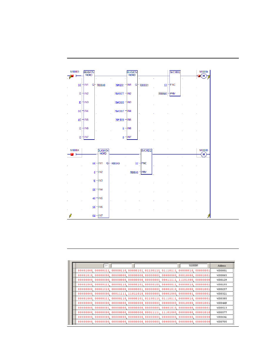
Example 3: Writing Over Data in Reference Memories 

By  changing  values,  the  same  logic  can  be  used  to  write  over  some  data  in  the  same 
reference memories. 

Figure 384 


Results of Example 3 

In this example, the status words returned for Service Request begin at PLC reference 
%G00321. 

Figure 385 


User Manual 

Chapter 27 

GFK-1645M 

Dec 2019 


Reading and Writing Data in Flash Memory 

579 

Example 4: Multiple Writes and Reads 

This four-part example shows how to perform multiple reads and writes on a 64-point CPU. 

Example 4, Part 1 

The first part of this example: 

Writes %R0001 through %R0010 from PLC reference memory to flash. Return Write status 
data to PLC references starting at %R0051. 

Reads  back  %R0001  through  %R0010  from  flash  into  CPU  references  %R0061  through 
%R0070. It returns status data into PLC references starting at %R0071. 

Figure 386 


User Manual 

Chapter 27 

GFK-1645M 

Dec 2019 


Reading and Writing Data in Flash Memory 

580 

Results of Example 4, Part 1 

Looking at the references used by this part of Example 4: 


%R0051 shows the Write status as 1. That means all data was successfully written. 


%R0052 shows that 10 words of data have been written to flash.  


%R0053  shows  the  remaining  available  flash  memory  as  8158  bytes.  Note:  The 
available memory will be 65518 for 14, 23, or 28-point Micro PLCs. 

The Read status references are not shown here. 

Figure 387 


Example 4, Part 2 

The next part of Example 4: 

1.


Writes the contents of PLC references %R0015 through %R0024 into flash. It returns 
Write status data to PLC references starting at %R0081. 

2.


Reads  flash  references  %R0015  through  %R0024  into  PLC  references  %R0091 
through %R0100 and returns Read status information to PLC references starting at 
%R0101. 


User Manual 

Chapter 27 

GFK-1645M 

Dec 2019 


Reading and Writing Data in Flash Memory 

581 

Figure 388 


User Manual 

Chapter 27 

GFK-1645M 

Dec 2019 


Reading and Writing Data in Flash Memory 

582 

Results of Example 4, Part 2 

For Example 4, Part 2, the Write status references start at %R0081: 


%R0081 shows status as 1 signifying full success (all data written) 


%R0082 shows that 10 words of data have been stored 


%R0083 shows that the available flash memory is 8132 

The Read status references, which start at %R101, are not shown here. However, the Write 
status references from part 1 of this example, starting at %R0051, are shown. 

Figure 389 


Example 4, Part 3 

This part of Example 4: 

1.


Writes  PLC  references  %R0008  through  %R0017  to  flash  and  returns  Write  status 
data to PLC references starting at %R0111. This single Service Request: 


Overwrites the values in %R0008 through %R0010 that were written in Example 
4 Part 1. 


Writes new data into %R0011 through %R0014. 


Overwrites the values in %R0015 through %R0017 that were written in Example 
4 Part 2. 

2.


Reads  %R0008  through  %R017  from  flash  into  PLC  references  %R0121  through 
%R0130 and returns Read status data to PLC references starting at %R0131. 


User Manual 

Chapter 27 

GFK-1645M 

Dec 2019 


Reading and Writing Data in Flash Memory 

583 

Figure 390 


User Manual 

Chapter 27 

GFK-1645M 

Dec 2019 


Reading and Writing Data in Flash Memory 

584 

Results of Example 4, Part 3 

For Example, 4, Part 3, the Write status references start at %R0111: 


The value in status reference %R0111 is 257 (0x0101). That indicates partial success, 
because not all 10 bytes of data were written to flash. Error 257 may occur if some 
requested data is already stored in user flash, as was done in this example.  


%R0112 shows that only 7 words of data were stored, not the 10 words requested.  


%R0113 shows that the remaining available flash memory is 8112 bytes. 

The Read status references start at %R0131: 


%R0131 shows that the Read Service Request completed successfully. 


%R0132 shows that 10 words of data were read. 

Figure 391 


User Manual 

Chapter 27 

GFK-1645M 

Dec 2019 


Reading and Writing Data in Flash Memory 

585 

Example 4, Part 4 

This part of the example program logic: 

1.


Reads  flash  references  %R0011  through  %R0020  into  PLC  references  %R0141 
through  %R0150  and  returns  Read  status  information  to  PLC  memory  starting  at 
%R0151. 

2.


Reads  flash  references  %R0021  through  %R0030  into  PLC  references  %R0161 
through  %R0170  and  returns  Read  status  information  to  PLC  memory  starting  at 
%R0171. 

Figure 392 


User Manual 

Chapter 27 

GFK-1645M 

Dec 2019 


Reading and Writing Data in Flash Memory 

586 

Results of Example 4, Part 4 

For Example 4, Section 4, the Read status references start at %R0151 and %R0171: 


The value in Read status reference %R0151 is 1. The Read operation was successful.  


%R0152 shows that all 10 words of data were read into PLC memory.  


The value in Read status reference %R0171 is 257 (0x0101). That indicates partial 
success, because not all 10 bytes of data were written to flash. That can occur if not 
enough memory is available in the selected PLC reference area for the data that has 
been read from flash. 


%R0172 shows that only 4 words of data were read. 

Figure 393 


User Manual 

Appendix A 

GFK-1645M 

Dec 2019 


Instruction Timing 

587 

Appendix A:


Instruction Timing 

This appendix contains tables listing the memory size in bytes and the execution times in 
microseconds for each function supported by a VersaMax Nano PLC or Micro PLC.  


Notes on Timing Information  


Typical Execution Times for Boolean Contacts 


Typical Execution Times for Release 4.0 CPUs 


Typical Execution Times for Release 3.8 CPUs 


Typical Execution Times for Release 3.0 CPUs 


Typical Execution Times for Release 2.0 CPUs 


Typical Execution Times for Release 1.1 CPUs 


Typical Execution Times for Release 1.0 CPUs 

A-1


Notes on the Timing Information 

A-1.1


Execution Times with Function Block Enabled or 
Disabled 

Two  execution  times  are  shown  for  each  type  of  function  block,  labeled  "enabled"  and 
"disabled".  

For each instance of the function block in the logic program: 


the value in the "enabled" column represents a range of typical contribution times 
when the function block receives power flow during that sweep. 


the value in the "disabled" column represents the typical contribution time when the 
function block is not receiving power flow during that sweep and/or there is power 
flow to reset of the function block.  


All timing values represent typical execution time. Actual execution time may vary 
with input and error conditions. 

A-1.2


Additional Notes 

1.


Timers and counters are updated each time they are encountered in the logic; timers 
by the amount of time consumed by the last sweep and counters by one count.  

2.


For bit operation functions, L = the number of bits. For bit position, N = the bit that 
is set. For data move functions, N = the number of bits or words. B= the number of 
bits shifted more than 1 (that is, not counting the first bit). W = the number of words. 

3.


Memory  size  refers  to  the  number  of  bytes  required  by  the  function  in  a  ladder 
diagram application program.  

4.


For table functions, increment is in units of length specified.  

5.


Enabled time for single length units of type %R, %AI, and %AQ. 

User Manual 

Appendix A 

GFK-1645M 

Dec 2019 


Instruction Timing 

588 

6.


The DO I/O function block timing represents execution on 8 points (%I0001 to 
%I0008). 

A-2


Typical Execution Times for Boolean Contacts 

Boolean contact execution times for Boolean logic are as follows: 


CPU Releases 


3.8 

3.0 

2.0, 1.10  1.07 

1.05 

1.0 

10-point Nano PLCs 

1.4 ms/K  1.3 ms/K 

1.3 ms/K 

N/A 

N/A 

1.2 ms/K 

14-point Micro PLCs 

1.5 ms/K  1.1 ms/K 

1.1 ms/K 

N/A 

N/A 

1.0 ms/K 

20-point Micro PLCs 

1.7 ms/K  N/A 

N/A 

N/A 

N/A 

N/A 

23-point Micro PLCs 

1.5 ms/K  1.1 ms/K 

1.1 ms/K 

N/A 

N/A 

1.0 ms/K 

28-point Micro PLCs 

1.5 ms/K  1.1 ms/K 

1.1 ms/K 

N/A 

1.0 ms/K 

1.0 ms/K 

40-point Micro PLCs 

1.7 ms/K  N/A 

N/A 

N/A 

N/A 

N/A 

28-point Micro PLC 
with ESCP 
(IC200UDD120) 

1.3 ms/K  1.0 ms/K 

1.0 ms/K 

1.0 ms/K 

N/A 

N/A 

64-point Micro PLC 

1.7 ms/K  1.7 ms/K 

N/A 

N/A 

N/A 

N/A 

A-2.1


Sweep Times for Micro-64 CPUs 

No expansion units connected = 2.9ms to 3.1ms 

With 1 expansion unit = 3.5ms to 3.8ms 

With 2 expansion unit = 3.8ms to 4ms 

With 3 expansion unit = 4.3ms to 4.5ms 

With 4 expansion unit = 4.4ms to 5ms 


User Manual 

Appendix A 

GFK-1645M 

Dec 2019 


Instruction Timing 

589 

A-3


Typical Execution Times for Release 4.0 CPUs 

The following table details function block timing for Release 4.0, Micro PLCs.  

For each instance of a function block, the table shows typical execution times when the 
function block is enabled (receiving power flow) or disabled (not receiving power flow).  


Execution Time 
(Range in µsec.) 


20-/40-/64-Point 

Group 

Function 

Size bytes 

Enabled 

Disabled 

Timers 

Off Delay Timer 

15 

93 

63 

On Delay Timer 

15 

97 

70 

Elapsed Timer 

15 

70 

51 

Counters 

Up Counter 

13 

64 

59 

Down Counter 

13 

59 

57 

Math 

Addition (INT) 

13 

39 

Addition (DINT) 

19 

52 

Addition (REAL) 

17 

138 

Subtraction (INT) 

13 

34 

Subtraction (DINT) 

19 

40 

Subtraction (REAL) 

17 

153 

Multiplication (INT) 

13 

43 

Multiplication (DINT) 

13 

33 

Multiplication (REAL) 

17 

145 

Division (INT) 

13 

58 

Division (DINT) 

19 

43 

Division (REAL) 

17 

237 

Modulo Division (INT) 

13 

57 

Modulo Division (DINT) 

19 

59 

Square Root (INT) 

10 

55 

Square Root (DINT) 

13 

46 

Square Root (REAL) 

11 

557 

Trigonometric 

SIN (REAL) 

11 

1534 

COS (REAL) 

11 

1630 

TAN (REAL) 

11 

2316 

12 

ASIN (REAL) 

11 

1638 

ACOS (REAL) 

11 

1638 

ATAN (REAL) 

11 

951 

Logarithmic 

LOG (REAL) 

11 

1001 

LN (REAL) 

11 

915 

User Manual 

Appendix A 

GFK-1645M 

Dec 2019 


Instruction Timing 

590 


Execution Time 
(Range in µsec.) 


20-/40-/64-Point 

Group 

Function 

Size bytes 

Enabled 

Disabled 

Exponential 

Power of e 

11 

703 

Power of X 

11 

368 

Radian Conv 

Convert RAD to DEG 

11 

379 

Convert DEG to RAD 

17 

79 

Relational 

Equal (INT) 

10 

35 

Equal (DINT 

16 

25 

Equal (REAL) 

14 

40 

Not Equal (INT) 

10 

22 

Not Equal (DINT) 

16 

38 

Not Equal (REAL) 

14 

46 

Greater Than (INT) 

10 

31 

Greater Than (DINT) 

16 

30 

Greater Than (REAL) 

14 

41 

10 

Greater Than/Equal (INT) 

10 

22 

Greater Than/Equal (DINT) 

16 

24 

Greater Than/Equal (REAL) 

14 

36 

Less Than (INT) 

10 

22 

Less Than (DINT) 

16 

24 

Less Than (REAL) 

14 

36 

Less Than/Equal (INT) 

10 

21 

Less Than/Equal (DINT) 

16 

24 

Less Than/Equal (REAL) 

14 

40 

Range (INT) 

13 

26 

Range (DINT) 

22 

29 

Range (WORD) 

13 

26 

Bit Operation 

Logical AND 

13 

33 

Logical OR 

13 

32 

Logical Exclusive OR 

13 

33 

Logical Invert, NOT 

10 

28 

Shift Bit Left 

16 

204 

10 

Shift Bit Right 

16 

139 

10 

Rotate Bit Left 

16 

88 

Rotate Bit Right 

16 

106 

Bit Position 

13 

57 

Bit Clear 

13 

57 

Bit Test 

13 

35 

User Manual 

Appendix A 

GFK-1645M 

Dec 2019 


Instruction Timing 

591 


Execution Time 
(Range in µsec.) 


20-/40-/64-Point 

Group 

Function 

Size bytes 

Enabled 

Disabled 

Bit Set 

13 

52 

Mask Compare (WORD) 

25 

129 

Mask Compare (DWORD) 

25 

113 

Data Move 

Move (INT) 

10 

27 

Move (BOOL) 

13 

62 

Move (WORD) 

10 

26 

Move (REAL) 

13 

41 

Block Move (INT) 

28 

34 

Block Move (WORD) 

28 

34 

Block Move (REAL) 

13 

61 

11 

Block Clear (WORD) 

11 

59 

Shift Register (BIT) 

16 

103 

10 

Shift Register (WORD) 

16 

85 

10 

Bit Sequencer 

16 

97 

93 

COMMREQ 

13 

1035 

245 

Table 

Array Move (INT) 

22 

83 

Array Move(DINT) 

22 

71 

Array Move (BOOL) 

22 

116 

Array Move (BYTE) 

22 

77 

Array Move (WORD) 

22 

83 

Search Equal (INT) 

19 

70 

Search Equal (DINT) 

22 

62 

Search Equal (BYTE) 

19 

56 

Search Equal (WORD) 

19 

70 

Search Not Equal (INT) 

19 

61 

Search Not Equal (DINT) 

22 

71 

Search Not Equal (BYTE) 

19 

55 

Search Not Equal (WORD) 

19 

68 

Search Greater/Equal (INT) 

19 

65 

Search Greater/Equal (DINT) 

22 

70 

Search Greater/Equal (BYTE) 

19 

44 

Search Greater/Equal (WORD) 

19 

61 

Search Greater Than (INT) 

19 

82 

Search Greater Than (DINT) 

22 

82 

Search Greater Than (BYTE) 

19 

55 

Search Greater Than (WORD) 

19 

70 

User Manual 

Appendix A 

GFK-1645M 

Dec 2019 


Instruction Timing 

592 


Execution Time 
(Range in µsec.) 


20-/40-/64-Point 

Group 

Function 

Size bytes 

Enabled 

Disabled 

Search Less Than (INT) 

19 

66 

Search Less Than (DINT) 

22 

78 

Search Less Than (BYTE) 

19 

43 

Search Less Than (WORD) 

19 

64 

Search Less/Equal (INT) 

19 

64 

Search Less/Equal (DINT) 

22 

60 

Search Less/Equal (BYTE) 

19 

56 

Search Less/Equal (WORD) 

19 

64 

Conversion 

Convert INT to REAL 

10 

53 

Convert REAL to INT 

13 

766 

Convert DINT to REAL 

13 

45 

Convert REAL to DINT 

13 

757 

Convert WORD to REAL 

10 

35 

Convert REAL to WORD 

13 

757 

Convert BDC to INT 

10 

40 

Convert INT to BCD 

10 

109 

Convert BCD to REAL 

10 

47 

Truncate to INT 

13 

175 

Truncate to DINT 

13 

156 

Control 

Call a Subroutine 

36 

Do I/O 

13 

275 

Service Request #6 

10 

90 

Service Request #7 Read 

10 

426 

Service Request #7 Write 

10 

1012 

Service Request #9 

10 

145 

Service Request #14 

10 

315 

Service Request #15 

10 

25 

Service Request #16 

10 

162 

Service Request #18 

10 

81 

Service Request #23 

10 

316 

Service Request #26, #30 

10 

510 

Service Request #29 

10 

92 

Service Request #34 

10 

11 

Service Request #35 

10 

19 

17 

Service Request #52 

10 

420 

Service Request #53 

10 

1082 

User Manual 

Appendix A 

GFK-1645M 

Dec 2019 


Instruction Timing 

593 


Execution Time 
(Range in µsec.) 


20-/40-/64-Point 

Group 

Function 

Size bytes 

Enabled 

Disabled 

Nested MCR/ENDMCR 

PID-ISA Algorithm 

16 

236 

59 

PID-IND Algorithm 

16 

236 

59 

Communication  MODBUS_TCP_RW

21


41 

214 

40 

A-4


Typical Execution Times for Release 3.8 CPUs 

The following table details function block timing for Release 3.8, Micro PLCs.  

For each instance of a function block, the table shows typical execution times when the 
function block is enabled (receiving power flow) or disabled (not receiving power flow).  


Execution Time (Range in µsec.)  
per PLC Type 


20-/40-/64-Point 

Group 

Function 

Size bytes 

Enabled 

Disabled 

Timers 

Off Delay Timer 

15 

68-76 

49-56 


On Delay Timer 

15 

70-78 

55-62 


Elapsed Timer 

15 

69-74 

36-42 

Counters 

Up Counter 

13 

44-51 

40-47 


Down Counter 

13 

64-71 

62-69 

Math 

Addition (INT) 

13 

33-38 

4-10 

Addition (DINT) 

19 

45-51 

4-10 

Addition (REAL) 

17 

134-139 

4-10 

Subtraction (INT) 

13 

24-29 

3-8 

Subtraction (DINT) 

19 

29-34 

3-8 

Subtraction (REAL) 

17 

104-109 

3-8 

Multiplication (INT) 

13 

37-42 

4-10 

Multiplication (DINT) 

13 

28-33 

4-10 

Multiplication (REAL) 

17 

134-139 

4-10 

Division (INT) 

13 

54-59 

4-10 

Division (DINT) 

19 

42-47 

5-10 

Division (REAL) 

17 

220-225 

5-10 

Modulo Division (INT) 

13 

45-50 

5-10 

Modulo Division (DINT) 

19 

54-60 

5-10 

Square Root (INT) 

10 

29-34 

3-8 

Square Root (DINT) 

13 

34-39 

3-8 


21


For the MODBUS_TCP_RW function block, time between Execute ON to busy ON is 720 µSec. 


Content      ..     37      38      39      40     ..