EMERSON PACSystems VersaMax MICRO PLC & NANO PLC. USER MANUAL (2019) - page 37
 

  Index      Manuals     EMERSON PACSystems VersaMax MICRO PLC & NANO PLC. USER MANUAL (2019)


Search            copyright infringement  


Content      ..     35      36      37      38     ..


EMERSON PACSystems VersaMax MICRO PLC & NANO PLC. USER MANUAL (2019) - page 37


User Manual 

Chapter 25 

GFK-1645M 

Dec 2019 


Serial I/O, SNP & RTU Protocols 

546 

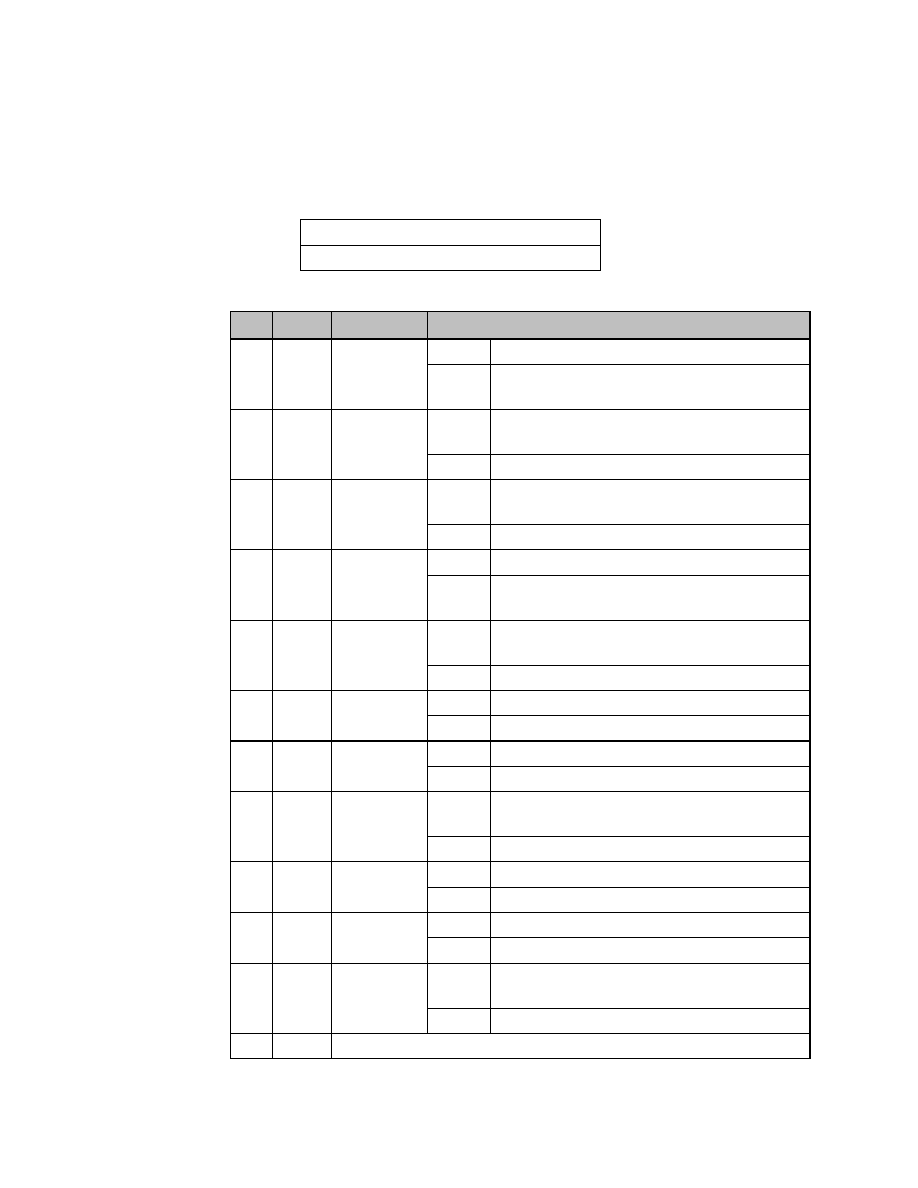
Port Status 

The port status consists of a status word and the number of characters in the input buffer 
that have not been retrieved by the application (characters which have been received and 
are available). 

word 1 

Port status word (see below) 

word 2 

Characters available in the input buffer 

The Port Status Word can be: 

Bit 

Name  Definition 

Meaning 

15 

RI 

Read In 
progress 

Set 

Read Bytes or Read String invoked 

Cleared 

Previous Read bytes or String has timed out, been 
canceled, or finished 

14 

RS 

Read Success  Set 

Read Bytes or Read String has successfully 
completed 

Cleared 

New Read Bytes or Read String invoked 

13 

RT 

Read Time-
out  

Set 

Receive timeout occurred during Read Bytes or Read 
String 

Cleared 

New Read Bytes or Read String invoked 

12 

WI 

Write In 
progress 

Set 

New Write Bytes invoked 

Cleared 

Previously invoked Write Bytes has timed out, been 
canceled, or finished 

11 

WS 

Write 
Success 

Set 

Previously invoked Write Bytes has successfully 
completed  

Cleared 

New Write Bytes invoked 

10 

WT 

Write Time-
out  

Set 

Transmit timeout during Write Bytes 

Cleared 

New Write Bytes invoked 

CA 

Character 
Available 

Set 

Unread characters are in the buffer 

Cleared 

No unread characters in the buffer 

OF 

OverFlow 
error  

Set 

Overflow error occurred on the serial port or internal 
buffer 

Cleared 

Read Port Status invoked 

FE 

Framing Error   Set 

Framing error occurred on the serial port 

Cleared 

Read Port Status invoked 

PE 

Parity Error  

Set 

Parity error occurred on the serial port 

Cleared 

Read Port Status invoked 

CT 

CTS is active 

Set 

CTS line on the serial port is active or the serial port 
does not have a CTS line 

Cleared 

CTS line on the serial port is not active 

4 - 0   U 

not used, should be 0 


User Manual 

Chapter 25 

GFK-1645M 

Dec 2019 


Serial I/O, SNP & RTU Protocols 

547 

25.4.6


Write port control Function (4304) 

This function forces RTS  for the specified port: 

Example Command Block for the Write Port Control Function 


Value 
(decimal) 

Value 
(hexadecimal) 

Meaning 

address 

0002 

0002 

Data block length 

address +1  0000 

0000 

NOWAIT mode 

address +2  0008 

0008 

Status word memory type (%R) 

address +3  0000 

0000 

Status word address minus 1 (%R0001) 

address +4  0000 

0000 

Not used 

address +5  0000 

0000 

Not used 

address +6  4304 

10D0 

Write port control command 

address +7  xxxx 

xxxx 

Port control word 

Port Control Word 

15 

14 

13 

12 

11 

10 

RTS 

The Port Control Word can be: 

15 

RTS 

Commanded state of the RTS output 


1 = Activates RTS 


0 = Deactivates RTS 

0-14 

Unused (should be zero) 

Operating Note 

For  Micro  PLC  port  2  (RS-485),  the  RTS  signal  is  also  controlled  by  the  transmit  driver. 
Therefore, control of RTS is dependent on the current state of the transmit driver. If the 
transmit driver is not enabled, asserting RTS with the Write Port Control COMMREQ will not 
cause RTS to be asserted on the serial line. The state of the transmit driver is controlled by 
the protocol and is dependent on the current Duplex Mode of the port. For 2-wire and 4-
wire Duplex Mode, the transmit driver is only enabled during transmitting. Therefore, RTS 
on the serial line will only be seen active on port 2 (configured for 2-wire or 4-wire Duplex 
Mode) when data is being transmitted. For point-to-point Duplex Mode, the transmit driver 
is  always  enabled.  Therefore,  in  point-to-point  Duplex  Mode,  RTS  on  the  serial  line  will 
always reflect what is chosen with the Write Port Control COMMREQ. 


User Manual 

Chapter 25 

GFK-1645M 

Dec 2019 


Serial I/O, SNP & RTU Protocols 

548 

25.4.7


Cancel COMMREQ Function (4399) 

This function cancels the current operations in progress. It can be used to cancel both read 
operations and write operations. If a read operation is in progress and there are unprocessed 
characters in the input buffer, those characters are left in the input buffer and available for 
future reads.  The serial port is not reset. 

Example Command Block for the Cancel COMMREQ Function 


Value 
(decimal) 

Value 
(hexadecimal) 

Meaning 

address 

0002 

0002 

Data block length 

address +1 

0000 

0000 

NOWAIT mode 

address +2 

0008 

0008 

Status word memory type (%R) 

address +3 

0000 

0000 

Status word address minus 1 (%R0001) 

address +4 

0000 

0000 

Not used 

address +5 

0000 

0000 

Not used 

address +6 

4399 

112F 

Cancel operation command 

address +7 

0001 

0001 

Transaction type to cancel 
 

All operations 


Read operations 


Write operations 

Operating Notes 

This function does not update the status of words of the cancelled COMMREQs. 

CAUTION 

If this COMMREQ is sent in either Cancel All or Cancel Write mode when a Write Bytes (4401) 
COMMREQ is transmitting a string from a serial port, transmission is halted. The position 
within  the  string  where  the  transmission  is  halted  is  indeterminate.  In  addition,  the  final 
character received by the device the Micro PLC is sending to is also indeterminate. 


User Manual 

Chapter 25 

GFK-1645M 

Dec 2019 


Serial I/O, SNP & RTU Protocols 

549 

25.4.8


Autodial Function (4400) 

This  feature  allows  the  VersaMax  Micro  PLC  to  automatically  dial  a  modem  and  send  a 
specified byte string.  

To implement this feature, the port must be configured for Serial I/O. 

For example, pager enunciation can be implemented by three commands, requiring three 
COMMREQ command blocks: 


Autodial: 

04400 
(1130h) 

Dials the modem.  


Write Bytes: 

04401 
(1131h) 

Specifies an ASCII string, from 1 to 250 bytes in length, to 
send from the serial port. 


Autodial: 

04400 
(1130h) 

It is the responsibility of the Micro PLC application 
program to hang up the phone connection. This is 
accomplished by reissuing the autodial command and 
sending the hang up command string. 

Autodial Command Block 

The Autodial command automatically transmits an Escape sequence that follows the Hayes 
convention. If you are using a modem that does not support the Hayes convention, you may 
be able to use the Write Bytes command to dial the modem. 

Examples  of  commonly  used  command  strings  for  Hayes-compatible  modems  are  listed 
below:  

Command String 

Length 

Function 

ATDP15035559999<CR> 

16 (10h) 

Pulse dial the number 1-503-555-9999 

ATDT15035559999<CR> 

16 (10h) 

Tone dial the number 1-503-555-9999 

ATDT9,15035559999<CR> 

18 (12h) 

Tone dial using outside line with pause 

ATH0<CR> 

5 (05h) 

Hang up the phone 

ATZ <CR> 

4 (04h) 

Restore modem configuration to internally saved 
values 


User Manual 

Chapter 25 

GFK-1645M 

Dec 2019 


Serial I/O, SNP & RTU Protocols 

550 

Example Autodial Command Block 

This  example  COMMREQ  command  block  dials  the  number  234-5678  using  a  Hayes-
compatible modem. 

Word 

Definition 

Values 

0009h 

CUSTOM data block length (includes command string) 

0000h 

NOWAIT mode 

0008h 

Status word memory type (%R) 

0000h 

Status word address minus 1 (Register 1) 

0000h 

not used 

0000h 

not used 

04400 (1130h)  Autodial command number 

00030 (001Eh)  Modem response timeout (30 seconds) 

0012 (000Ch) 

Number of bytes in command string 

10 

5441h 

A (41h), T (54h) 

11 

5444h 

D (44h), T (54h) 

12 

3332h 

Phone number:  2 (32h), 3 (33h) 

13 

3534h 


4 (34h), 5 (35h) 

14 

3736h 


6 (36h), 7 (37h) 

15 

0D38h 


8 (38h) <CR> (0Dh) 

25.4.9


Write bytes Function (4401) 

This operation can be used to transmit one or more characters to the remote device through 
the specified serial port.  The character(s) to be transmitted must be in a word reference 
memory. They should not be changed until the operation is complete.   

Up to 250 characters can be transmitted with a  single  invocation of this operation.  The 
status of the operation is not complete until all of the characters have been transmitted or 
until a timeout occurs (for example, if hardware flow control is being used and the remote 
device never enables the transmission). 

Example Command Block for the Write Bytes Function 


Value 
(decimal) 

Value 
(hexadecima
l) 

Meaning 

address 

0006 

0006 

Data block length (includes characters to send) 

address +1 

0000 

0000 

NOWAIT mode 

address +2 

0008 

0008 

Status word memory type (%R) 

address +3 

0000 

0000 

Status word address minus 1 (%R0001) 

address +4 

0000 

0000 

Not used 

address +5 

0000 

0000 

Not used 

address +6 

4401 

1131 

Write bytes command 

User Manual 

Chapter 25 

GFK-1645M 

Dec 2019 


Serial I/O, SNP & RTU Protocols 

551 


Value 
(decimal) 

Value 
(hexadecima
l) 

Meaning 

address +7 

0030 

001E 

Transmit time-out (30 seconds). See note 
below. 

address +8 

0005 

0005 

Number of bytes to write 

address +9 

25960 

6568 

‘h’ (68h), ‘e’ (65h)


address +10 

27756 

6C6C 

‘l’ (6Ch), ‘l’ (6Ch)


address +11 

0111 

006F 

‘o’ (6Fh)


Although printable ASCII characters are used in this example, there is no restriction on the 
values of the characters that can be transmitted. 

Operating Notes 

Note: 

Specifying zero as the Transmit time-out sets the time-out value to the amount of time actually 
needed to transmit the data, plus 4 seconds. 

CAUTION 

If an Initialize Port (4300) COMMEQ is sent or a Cancel Operation (4399) COMMREQ is sent 
in either Cancel All or Cancel Write mode while this COMMREQ is transmitting a string from 
a serial port, transmission is halted. The position within the string where the transmission 
has halted is indeterminate. In addition, the final character received by the device the Micro 
PLC is sending to is also indeterminate. 

25.4.10


Read bytes Function (4402) 

This  function  causes  one  or  more  characters  to  be  read  from  the  specified  port.    The 
characters are read from the internal input buffer and placed in the specified input data area. 

The  function  returns  both  the  number  of  characters  retrieved  and  the  number  of 
unprocessed characters still in the input buffer.  If zero characters of input are requested, 
only the number of unprocessed characters in the input buffer is returned.   

If insufficient characters are available to satisfy the request and a non-zero value is specified 
for the number of characters to read, the status of the operation is not complete until either 
sufficient characters have been received or the time-out interval expires.  In either of those 
conditions, the port status indicates the reason for completion of the read operation. The 
status word is not updated until the read operation is complete (either due to timeout or 
when all the data has been received). 

If the time-out interval is set to zero, the COMMREQ remains pending until it has received 
the requested amount of data, or until it is cancelled. 

If this COMMREQ fails for any reason, no data is returned to the buffer. Any data that was 
already in the buffer remains and can be retrieved with a subsequent read request. 

User Manual 

Chapter 25 

GFK-1645M 

Dec 2019 


Serial I/O, SNP & RTU Protocols 

552 

Example Command Block for the Read Bytes Function 


Value 
(decimal) 

Value 
(hexadecimal) 

Meaning 

address 

0005 

0005 

Data block length 

address +1 

0000 

0000 

NOWAIT mode 

address +2 

0008 

0008 

Status word memory type (%R) 

address +3 

0000 

0000 

Status word address minus 1 (%R0001) 

address +4 

0000 

0000 

Not used 

address +5 

0000 

0000 

Not used 

address +6 

4402 

1132 

Read bytes command 

address +7 

0030 

001E 

Read time-out (30 seconds) 

address +8 

0005 

0005 

Number of bytes to read 

address +9 

0008 

0008 

Input data memory type (%R).  

address +10 

0001 

0001 

Input data memory address (%R0001) 

Return Data Format for the Read Bytes Function 

The return data consists of the number of characters actually read, the number of characters 
still  available  in  the  input  buffer  after  the  read  is  complete  (if  any),  and  the  actual  input 
characters.  

Address 

Number of characters actually read 

Address + 1 

Number of characters still available in the input buffer, if any 

Address + 2 

first two characters (first character is in the low byte) 

Address + 3 

third and fourth characters (third character is in the low byte) 

Address + n 

subsequent characters 

Operating Note 

If the input data memory type parameter is specified to be a word memory type and an 
odd number of bytes are actually received, then the high byte of the last word to be 
written with the received data is set to zero. 

As data is received from the serial port it is placed in the internal input buffer.  If the buffer 
becomes full, then any additional data received from the serial port is discarded and the 
Overflow Error bit in the Port Status word (See Read Port Status Function) is set.  


User Manual 

Chapter 25 

GFK-1645M 

Dec 2019 


Serial I/O, SNP & RTU Protocols 

553 

25.4.11


Read String Function (4403) 

This  function  causes  characters  to  be  read  from  the  specified  port  until  a  specified 
terminating character is received. The characters are read from the internal input buffer and 
placed in the specified input data area. 

The  function  returns  both  the  number  of  characters  retrieved  and  the  number  of 
unprocessed characters still in the input buffer.  If zero characters of input are requested, 
only the number of unprocessed characters in the input buffer is returned.  

If  the  terminating  character  is  not  in  the  input  buffer,  the  status  of  the  operation  is  not 
complete until either the terminating character has been received or the time-out interval 
expires.  In either of those conditions, the port status indicates the reason for completion of 
the read operation. 

If the time-out interval is set to zero, the COMMREQ remains pending until it has received 
the requested string, terminated by the specified end character. 

If this COMMREQ fails for any reason, no data is returned to the buffer. Any data that was 
already in the buffer remains and can be retrieved with a subsequent read request. 

Example Command Block for the Read String Function 


Value 
(decimal) 

Value 
(hexadecimal) 

Meaning 

address 

0005 

0005 

Data block length 

address +1 

0000 

0000 

NOWAIT mode 

address +2 

0008 

0008 

Status word memory type (%R) 

address +3 

0000 

0000 

Status word address minus 1 (%R0001) 

address +4 

0000 

0000 

Not used 

address +5 

0000 

0000 

Not used 

address +6 

4403 

1133 

Read string command 

address +7 

0030 

001E 

Read time-out (30 seconds) 

address +8 

0013 

000D 

Terminating character (carriage return):  
must be between 0 and 255 (0xFF), 
inclusive 

address +9 

0008 

0008 

Input data memory type (%R) 

address +10 

0001 

0001 

Input data memory address (%R0001) 


User Manual 

Chapter 25 

GFK-1645M 

Dec 2019 


Serial I/O, SNP & RTU Protocols 

554 

Return Data Format for the Read String Function 

The return data consists of the number of characters actually read, the number of characters 
still  available  in  the  input  buffer  after  the  read  is  complete  (if  any),  and  the  actual  input 
characters: 

Address 

Number of characters actually read 

Address + 1 

Number of characters still available in the input buffer, if any 

Address + 2 

first two characters (first character is in the low byte) 

Address + 3 

third and fourth characters (third character is in the low byte) 

Address + n 

subsequent characters 

Operating Note 

If the input data memory type parameter is specified to be a word memory type and an odd 
number of bytes are actually received, then the high byte of the last word to be written with 
the received data is set to zero. 

As data is received from the serial port it is placed in the internal input buffer.  If the buffer 
becomes full, then any additional data received from the serial port is discarded and the 
Overflow Error bit in the Port Status word (See Read Port Status Function) is set. 

Example 

The following Block Move will set up values to perform a serial I/O port configuration. In this 
example, port 2 is being configured. The entries of the first Block Move set up the following: 

IN1 

Length of the data block, which is always16 for a configuration COMMREQ 

IN2 

Wait/No Wait flag: 0 for No Wait 

IN3 

Status Word pointer: 8 signifies %R 

IN4  

Status word pointer offset; this number is zero based, so 0 points to %R1 

IN5 

Idle timeout value; not used with No Wait mode 

IN6 

Maximum communication time; not used with No Wait mode 

IN7 

Command Word; FFF0 hex is the command for serial port setup 

In the second Block Move: 

IN1 

Protocol selector; 5 selects Serial I/O 

IN2 

Port mode; 0 selects slave mode 

IN3 

Data rate; 6 selects 19200 

IN4 

Parity; 1 selects odd 

IN5 

Flow control; 1 selects none 

IN6 

Turnaround delay; 0 selects none 

IN7 

Timeout; 0 selects none 

User Manual 

Chapter 25 

GFK-1645M 

Dec 2019 


Serial I/O, SNP & RTU Protocols 

555 

In the third Block Move: 

IN1 

Bits per character; 1 chooses 8 bits per character 

IN2 

Stop bits; 0 selects 1 stop bit 

IN3 

Interface; not used so set to 0 

IN4 

Duplex mode; 1 selects 4-wire 

IN5 

 IN7 

Not used 

Figure 373 


%R1 is used as the status word for the COMMREQ. The following rung clears the word before 
the COMMREQ is issued: 

Figure 374 


The following logic issues a COMMREQ for port 2. The SYSID is set to rack 0 slot 1. The TASK 
ID of 20 defines port 2. The IN-parameter points to %AI1 which is where all the configuration 
data was placed with the Block Move statements. If an error occurs, the bit COMMREQP1bad 
(%T6) will be set. 

Figure 375 


User Manual 

Chapter 25 

GFK-1645M 

Dec 2019 


Serial I/O, SNP & RTU Protocols 

556 

The following rung sets the bit COMMREQ Complete (%T7), which keeps the COMMREQ 
from being issued more than once and keeps the status from being overwritten. 

Figure 376 


User Manual 

Chapter 26 

GFK-1645M 

Dec 2019 


PID Function 

557 

Chapter 26:


PID Function 

This chapter describes the PID (Proportional plus Integral plus Derivative) function, which is 
used for closed-loop process control. The PID function compares feedback from a process 
variable with a desired process set point and updates a Control Variable based on the error. 


Format of the PID Function 


Operation of the PID Function 


Parameter Block for the PID Function 


PID Algorithm Selection 


Determining the Process Characteristics 


Setting Parameters Including Tuning Loop Gains 


Sample PID Call 

26.1


Format of the PID Function 

The PID function uses PID loop gains and other parameters stored in an array of 40 16 bit 
words  to  solve  the  PID  algorithm  at  the  desired  time  interval.  All  parameters  are  16-bit 
integer words. This allows %AI memory to be used for input Process Variables and %AQ to 
be used for output Control Variables. 

Figure 377 


The PID function does not pass power flow if there is an error in the configurable 
parameters. It can be monitored using a temporary coil while modifying data. 


User Manual 

Chapter 26 

GFK-1645M 

Dec 2019 


PID Function 

558 

26.1.1


Parameters of the PID Function 

Input/ 
Output 

Choices 

Description 

enable 

flow 

When enabled through a contact, the PID algorithm is performed. 

SP 

I, Q, M, T, G, R, AI, 
AQ, constant 

The control loop or process set point. Set using process variable 
counts, the PID function adjusts the output control variable so that 
the process variable matches the set point (zero error). 

PV 

I, Q, M, T, G, R, AI, 
AQ 

Process Variable input from the process being controlled, often a 
%AI input. 

MAN 

flow 

When energized to 1 (through a contact), the PID block is in 
manual  mode. If the PID block is on manual off, the PID block is in 
automatic mode. 

UP 

flow 

If energized along with MAN, it adjusts the control variable up by 1 
CV per solution.

20


DN 

flow 

If energized along with MAN, it adjusts the control variable down by 
1 CV per solution.

20


Address  R 

Location of the PID control block information (user and internal 
parameters).  Uses 40 %R words that cannot be shared.  

ok 

flow, none 

OK is energized when the function is performed without error. It is 
Off if errors exist. 

CV 

I, Q, M, T, G, R, AI, 
AQ 

The control variable output to the process, often a %AQ output. 

As scaled 16 integer numbers, many parameters must be defined in either Process Variable 
(PV) counts or units or Control Variable (CV) counts or units. For example, the Set Point (SP) 
input must be scaled over the same range as the Process Variable as the PID block calculates 
the error by subtracting these two inputs. The Process Variable and Control Variable Counts 
may  be 

32000  or  0  to  32000  matching  analog  scaling  or  from  0  to  10000  to  display 

variables as 0.00% to  100.00%. The Process  Variable  and Control Variable Counts do not 
have to have the same scaling, in which case there will be scale factors included in the PID 
gains. 


20


Incremented (UP parameter) or decremented (DN parameter) by one (1) per access of the PID function. 

User Manual 

Chapter 26 

GFK-1645M 

Dec 2019 


PID Function 

559 

26.2


Operation of the PID Function 

26.2.1


Automatic Operation 

The PID function can be called every sweep by providing power flow to Enable and no power 
flow to Manual input contacts. The block compares the current PLC elapsed time clock with 
the last PID solution time stored in the internal RefArray. If the difference is greater than the 
sample period defined in the third word (%Ref+2) of the RefArray, the PID algorithm is solved 
using  the  time  difference.  Both  the  last  solution  time  and  Control  Variable  output  are 
updated. In Automatic mode, the output Control Variable is placed in the Manual Command 
parameter %Ref+13. 

26.2.2


Manual Operation 

The PID block is placed in Manual mode by providing power flow to both the Enable and 
Manual  input  contacts.  The  output  Control  Variable  is  set  from  the  Manual  Command 
parameter %Ref+13. If either the UP or DN inputs have power flow, the Manual Command 
word is incremented or decremented by one CV count every PID solution. For faster manual 
changes of the output Control Variable, it is also possible to add or subtract any CV count 
value directly to/from the Manual Command word 

The PID block uses the CV Upper and CV Lower Clamp parameters to limit the CV output. If 
a positive Minimum Slew Time is defined, it is used to limit the rate of change of the CV 
output. If either the CV amplitude or rate limit is exceeded, the value stored in the integrator 
is adjusted so that CV is at the limit. This anti-reset windup feature means that even if the 
error tried to drive CV above (or below) the clamps for a long period of time, the CV output 
will move off the clamp as soon as the error term changes sign. 

This operation, with the Manual Command tracking CV in Automatic mode and setting CV 
in Manual mode, provides a bumpless transfer between Automatic and Manual modes. The 
CV Upper and Lower Clamps and the Minimum Slew Time still apply to the CV output in 
Manual mode and the internal value stored in the integrator is updated. This means that if 
you were to step the Manual Command in Manual mode, the CV output will not change any 
faster than the Minimum Slew Time (Inverse) rate limit and will not go above or below the 
CV Upper or CV Lower Clamp limits. 


User Manual 

Chapter 26 

GFK-1645M 

Dec 2019 


PID Function 

560 

26.2.3


Time Interval for the PID Function 

The PID will not execute more often than once every 10 milliseconds. If it is set up to execute 
every sweep and the sweep is under 10 ms, the PID function will not run until enough sweeps 
have occurred to accumulate an elapsed time of 10 ms. For example, if the sweep time is 9 
ms,  the  PID  function  executes  every  other  sweep,  so  the  overall  elapsed  time  between 
executions is 18 ms. A specific PID function should not be called more than once per sweep.  

The  longest  possible  interval  between  executions  is  10.9  minutes.  The  PID  function 
compensates for the actual time elapsed since the last execution within 100µS.   

The PID algorithm is solved only if the current Micro PLC elapsed time clock is at or later than 
the  last  PID  solution  time  plus  the  sample  period.      If  the  sample  period  is  set  to 0,  the 
function executes each time it is enabled; however, it  is restricted to a minimum of 10 ms 
as noted above. 

26.2.4


Scaling Input and Outputs 

All  parameters  of  the  PID  function  are  16  bit  integer  words  for  compatibility  with  16  bit 
analog  process  variables.  Some  parameters  must  be  defined  in  either  process  variable 
counts or units or control variable counts or units.  

The set point input must be scaled over the same range as process variable, because the PID 
function calculates error by subtracting these two inputs. The process variable and control 
variable counts do not have to use the same scaling. Either may be -32000 or 0 to 32000 to 
match analog scaling, or from 0 to 10000 to display variables as 0.00% to 100.00%. If the 
process and control variables do not use the same scaling, scale factors are included in the 
PID gains. 

Example of the PID Function 

The example shown below includes typical inputs. 

Figure 378 


User Manual 

Chapter 26 

GFK-1645M 

Dec 2019 


PID Function 

561 

26.3


Parameter Block for the PID Function  

The parameter block for the PID function occupies 40 words of %R memory. Many of the 40 
words are used by the Micro PLC and not configurable. Every PID function call must use a 
different 40-word memory area even if all 13 configurable parameters are the same.  

The  first  13  words  of  the  parameter  block  must  be  specified  before  executing  the  PID 
function. Zeros can be used for most default values. Once suitable PID values have been 
chosen,  they  can  be  defined  as  constants  in  a  BLKMOV  so  they  can  be  changed  by  the 
program as needed. 

26.3.1


Internal Parameters in RefArray 

The PID function reads 13 parameters and uses the rest of the 40-word RefArray for internal 
PID storage.  Normally you would not change these values.  If you call the PID block in Auto 
mode after a long delay, you may want to use SVCREQ 16 to load the current PLC elapsed 
time clock into %Ref+23 to update the last PID solution time to avoid a step change on the 
integrator. If you have set the Override low bit of the Control Word (%Ref+14) to 1, the next 
four bits of the Control Word must be set to control the PID block input contacts, and the 
Internal SP and PV must be set as you have taken control of the PID block away from the 
ladder logic. 


Parameter  Low Bit Units  Range 

Description 

Address 

Loop 
Number 

Integer 

0 to 255. 

Optional  number  of  the  PID  block.  It  provides  a 
common  identification  in  the  PLC  with  the  loop 
number defined by an operator interface device.   

Address +1 

Algorithm  

Set by the PLC 

1 = ISA algorithm 
2 = independent algorithm 

Address+2 

Sample 
Period  

10ms 

0 (every sweep) 
to 65535 (10.9 
Min) At least 
10ms. 

The  shortest  time,  in  10mS  increments,  between 
solutions of the PID algorithm. For example, use a 10 
for a 100mS sample period.  

Address+3 
Address+4 

Deadband + 
and 
Deadband - 

PV Counts 

0 to 32000 
(+ never 
negative) 
(- never positive) 

INT  values  defining  the  upper  (+)  and  lower  (-) 
Deadband  limits  in  PV  Counts.  If  no  Deadband  is 
required, these values must be 0.  If the PID Error (SP - 
PV) or (PV - SP) is above the (-) value and below the (+) 
value, the PID calculations are solved with an Error of 
0. If non-zero, the (+) value must greater than 0 and 
the  (-)  value  less  than  0  or  the  PID  block  will  not 
function.  
Leave these at 0 until the PID loop gains are set up or 
tuned.   A Deadband might be added to avoid small CV 
output changes due to variations in error. 


Content      ..     35      36      37      38     ..