Zoomlion Scissor lift ZS4555HD, ZS4045HD, ZS3246HD, ZS2632HD, ZS2032HD, ZS1930HD, ZS1530DC. Service and Maintenance Manual - page 2
b) Apply a thin layer of dry film lubrication to the area of the chassis where the scissor wear pads make
contact.
2.6.6 Maintenance every 24 months
Good quality hydraulic oil is essential to good machine performance and service life. Dirty hydraulic oil
and suction filters can affect machine performance, and continuous use can damage components. This
operation should be performed more frequently in harsh working conditions.
If the hydraulic oil has not been replaced for two years, it should be tested once every quarter, and the
hydraulic oil should be replaced if the test fails.
This procedure should be conducted once every quarter. The hydraulic oil should be replaced if the test
fails.
We suggest that changing time of the hydraulic oil is as follows:
a) First changing: operating for 500 hrs after commissioning.
b) Second and subsequent changing: run for 2000 hours or once every two years.
The above recommended intervals are suitable for most applications. Higher temperatures, pressures and
adverse working conditions will accelerate oil failure, so hydraulic oil should be replaced earlier. For
small load work, the oil change time can be extended.
For hydraulic oil types and models, please refer to Table 2-6 Hydraulic oil technical parameters (not used
to specify the type and parameters of hydraulic oil). Please select the hydraulic oil of the appropriate brand
and technical parameters according to the specific use environment of the equipment. For special
environments or users with special requirements, please contact ZOOMLION or hydraulic oil
manufacturers.
DO NOT mix oils of different brands or types, as they contain different additives which may cause
negative effects. If mixing of hydraulic oils is unavoidable, permission must be obtained from the
hydraulic oil manufacturer. After-sales service of ZOOMLION does not cover machine malfunction
caused by hydraulic oil mixing.
2-25
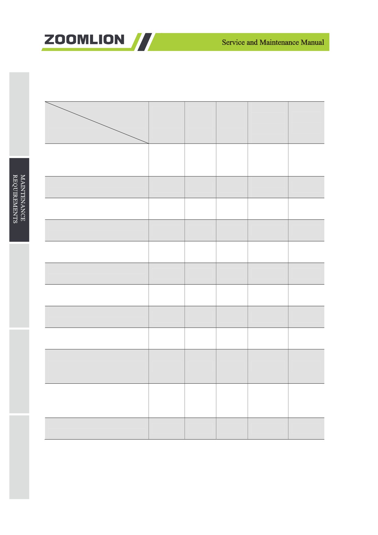
Table 2-6 Technical parameters of hydraulic oil
Kinematic
Technical
ISO
Pour
Flash
viscosity
Viscosity
Parameters
Viscosity
Point
Point
cSt(40℃
index
Brand & Type
Grade
℃/℉
℃/℉
/104℉)
Great Wall 4632 grease non-
flammable hydraulic oil N32
32
-20/-4
270/518
28.8-35.2
180
(Eco-Friendly)
Great Wall Ground 10
10.53(50℃
—
-55/-67
107/225
120
aviation hydraulic fluid
/122℉)
Great Wall ZhuoLi L-HS 15
15
-57/-71
164/327
15.35
172
Ultra-low temperature hydraulic
Great Wall ZhuoLi L-HS 32
32
-48/-54
224/435
31.35
166
Ultra-low temperature hydraulic
Great Wall ZhuoLi L-HS 46
46
-43/-45
238/460
45.81
170
Ultra-low temperature hydraulic
Great Wall ZhuoLi L-HV 15
15
-45/-49
173/343
15.51
140
Low temperature hydraulic oil
Great Wall ZhuoLi L-HV 32
32
-39/-38
231/448
33.4
150
Low temperature hydraulic oil
Great Wall ZhuoLi L-HV 46
46
-37/-35
240/464
48.7
150
Low temperature hydraulic oil
Great Wall ZhuoLi L-HV 68
68
-35/-31
238/460
70.47
150
Low temperature hydraulic
Great Wall ZhuoLi L-HM 46
Anti-wear hydraulic oil
46
-15/5
240/464
45.8
97
(high pressure)
Great Wall ZhuoLi L-HM 68
Anti-wear hydraulic oil (high
68
-13/9
245/473
67.4
98
pressure)
Mobil SHC Aware H 32
32
-30/-22
185/365
32
140
(Eco-Friendly)
2-26
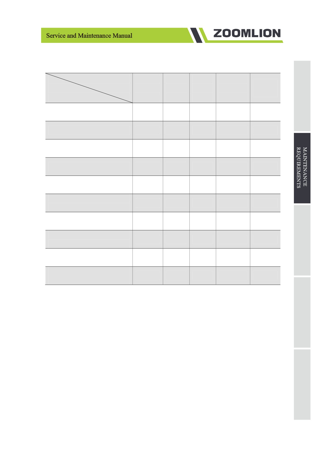
Table 2-6 Technical parameters of hydraulic oil
Technical
ISO
Pour
Flash
Kinematic
Viscosity
Parameters
Viscosity
Point
Point
viscosity
index
Brand & Type
Grade
℃
℃
cSt(40℃)
Clarity Synthetic EA
46
-44/-47
221/430
46
180
Hydraulic Oil
Mobil DTE 10 Ultra 22
22
-54/-65
224/435
22.4
164
Mobil DTE 10 Ultra 32
32
-54/-65
250/482
32.7
164
Mobil DTE 10 Ultra 46
46
-45/-49
232/450
45.6
164
CaltexRando
15
-60/-76
150/302
15.7
144
Rando HDZ 15
CaltexRando
32
-49/-56
204/399
33
150
Rando HDZ 32
CaltexRando
46
-47/-53
216/421
46.7
153
Rando HDZ 46
CaltexRando
15
-42/-44
154/309
15.8
155
Rando MV 15
CaltexRando
32
-36/-33
210/410
33.5
154
Rando MV 32
CaltexRando
46
-33/-27
214/417
44
154
Rando MV 46
Proper use of hydraulic oil: please note the corresponding oil viscosity and temperature limit. Under
normal operating conditions, the recommended oil temperature should be controlled between 30 °C/86℉
and 60 °C/140℉ and the maximum is not more than 90 °C/194℉. The oil temperature affects the oil
viscosity and the thickness of the oil film. High temperatures also shorten the service life of oil seals and
other rubber components, and the oil also evaporates and oxidizes.
Add the corresponding type of hydraulic oil according to the customer's requirements before ex-factory.
When the working environment temperature changes beyond the working range of the hydraulic oil,
please replace other suitable types of hydraulic oil according to the actual situation. Considering the safety
of the components and the efficiency of the work, it is recommended that the starting temperature of the
equipment is higher than the selected hydraulic oil pour point temperature of 25℃/77℉ or more.
Cleanliness of the hydraulic oil upon delivery is NAS9 (ISO4406 18/15), and for normal operation, the
cleanliness should not be lower than NAS10 (ISO4406 19/16). We suggest that the hydraulic oil should
be checked every 6 months, and the oil should be sampled at least once upon the time for oil changing.
2-27
The oil sample can be sent to the hydraulic oil manufacturer or qualified third-party testing agency for
analysis and to determine whether it is still usable.
This procedure should be conducted once every quarter. The hydraulic oil should be replaced if the test
fails.
a) Disconnect the battery pack from the machine.
Operation in a live circuit can result in serious injury or death. Remove rings, watches and other
jewelry.
a) Open the hydraulic tray.
b) Mark and disconnect the oil return tube from hydraulic filter to the hydraulic tank and remove the
line from the tank. Cover the pipe joint to protect it from dust.
c) Loosen the hydraulic tank fastener and remove the hydraulic tank.
d) Remove the drain plug from the bottom of the hydraulic tank.
e) Put the oil in a suitable container.
The jetted hydraulic oil can burn the skin. Slowly loosen the hydraulic joint to allow the oil pressure
to gradually weaken. Do not let the oil spray out.
a) Clean up and properly dispose any oil that may have spilled.
b) Clean the hydraulic tank with a mild solvent and thoroughly air dry.
c) Tighten the drain plug.
d) Replace the hydraulic tank and install the fasteners that tighten the hydraulic tank.
e) Oil the hydraulic pump and connect it to the tank.
f)
Connect the hydraulic pump tubing to the return filter.
g) Start the oil pump and fill the entire hydraulic system with hydraulic oil to remove the air from the
hydraulic system.
Operation without oil may result in damage to the hydraulic pump. When filling the hydraulic
system, carefully evacuate the tank. Do not expose the hydraulic pump to cavitation.
2-28
SECTION 3 ELECTRICAL SYSTEM MAINTENANCE
3.1 Electrical System Trouble shooting
If the platform controls LED or ground controls LCD diagnostic readout displays following codes, the
fault condition must repaired or removed before resuming machine operation.
3.1.1 Fault code
Table 3-1 Fault code list
Code
Condition
Machine Reaction
System initialization Fault
Disable All Motion
01
System communication Fault
Disable All Motion
02
Invalid option setting Fault
Disable All Motion
03
Calibration Fault
Disable All Motion
04
GPS communication Fault
Disable All Motion
09
CAN communication Fault
Disable All Motion
10
Chassis Up or Down Switch ON
Disable Chassis Control
12
Pothole Guard Fault
Disable Lifting and Driving
18
BMS Comm Fault
Disable Lifting and Driving
20
Disch Temp Fault I
Warning Only
21
Disch Current High Fault I
Warning Only
22
Disable Lifting, and Driving Lift
Total Voltage Low Fault I
23
Slow to Drive Speed
3-1
Table 3-1 Fault code list
Condition
Machine Reaction
Code
Disable Lifting, and Driving Lift
Cell Voltage Low Fault I
24
Slow to Drive Speed
Cell Voltage Low Fault II
Disables All Motion
25
Sharp Diff in Voltage
Disable All Motion
26
Sharp Diff in Temp
Disable All Motion
27
Disch Current High Fault II
Disable All Motion
28
Disch Temp Fault II
Disable All Motion
29
Pressure Sensor Fault
Disable All Motion
31
Angle Sensor Fault
Disable All Motion
32
Pressure Sensor 2 Fault
Disables All Motion
35
Battery Drain Alarm
Lift Slow to Drive Speed
36
Battery Drain Shutdown
Disable All Motion
37
SPI communication Fault
Disable All Motion
38
Platform Left Button ON
Diagnostic Message Only
42
Platform Right Button ON
Diagnostic Message Only
43
Platform Enable Button ON
Disable Platform Control
46
Joystick Not In Neutral
Lift Slow to Drive Speed
47
3-2
Table 3-1 Fault code list
Condition
Machine Reaction
Code
Horn Coil Fault
Disable All Motion
48
Forward Coil Fault
Disable Lifting and Driving
52
Reverse Coil Fault
Disable Lifting and Driving
53
Lift Up Coil Fault
Disable Lifting and Driving
54
Lift Down1 Coil fault
Disable Lifting and Driving
55
Right Turn Coil Fault
Disable Lifting and Driving
56
Left Turn Coil Fault
Disable Lifting and Driving
57
General Brake Coil Fault
Disable Lifting and Driving
58
Parallel Coil Fault
Disable Lifting and Driving
59
Motor Controller Fault
Disable All Motion
60
Motor Controller Current Sensor Fault
Disable All Motion
61
Motor Controller Hardware Failsafe Fault
Disable All Motion
62
Motor Controller Motor Short Fault
Disable All Motion
63
Motor Controller SRO Fault
Disable All Motion
64
Motor Controller Throttle Fault
Disable All Motion
65
Motor Controller Emergency Reverse Fault
Disable All Motion
66
Motor Controller HPD Fault
Disable All Motion
67
3-3
Table 3-1 Fault code list
Condition
Machine Reaction
Code
Total Voltage Low Fault II
Disable All Motion
68
High Neutral Current Fault (Zapi Only)
Disable All Motion
69
Steer Input Out of Range (Zapi Only)
Disable All Motion
70
Motor Controller Main Contractor Fault
Disable All Motion
71
Motor Controller Over Voltage Fault
Disable All Motion
72
Motor Controller Thermal Cutback Fault
Disable All Motion
73
Motor Controller Over Heat Fault
Disable All Motion
74
Motor Controller Pump Motor Fault
Disable All Motion
75
Motor Controller Left Drive Motor Fault
Disable All Motion
76
Motor Controller Right Drive Motor Fault
Disable All Motion
77
MC Pump Motor Short
Disable Lifting and Driving
78
Left Drive Motor Short Fault
Disable All Motion
79
Over 80% Load Warning
Diagnostic Message Only
80
Right Drive Motor Short Fault
Disable All Motion
81
Left Brake Coil Fault
Disable Lifting and Driving
82
Right Brake Coil Fault
Disable Lifting and Driving
83
Motor Post Shorted
Disable Lifting and Driving
84
Brake Release Switch On
Diagnostic Message Only
85
3-4
Table 3-1 Fault code list
Condition
Machine Reaction
Code
Brake Release Not Showed
Diagnostic Message Only
86
Brake Release
Diagnostic Message Only
87
Motor Field Open
Disable Lifting and Driving
89
Platform Load is over 90%
Diagnostic Message Only
90
Left Motor Field Short
Disable Lifting and Driving
91
Right Motor Field Short
Disable Lifting and Driving
92
Lift Down2 Coil fault
Disable Lifting and Driving
93
Over 99% Load Warning
Warning Only
99
Overloaded Platform Fault
Disable All Motion
0L
Machine Tiled
Disable Lifting and Driving
LL
3-5
3.1.2 Troubles shooting method
Table 3-2 Trouble shooting method
Code
Trouble shooting Method
System Initialization Fault: ECU may be malfunctioning, replace it.
01
System Communication Fault: Check communications cable connections and
02
other wiring. If that does not resolve the problem, try replacing the PCU or ECU.
Invalid Option setting Fault: Set appropriate option for this lift.
03
Calibration Fault: Re-calibration the system, or check the angle and pressure sensor.
04
GPS communication Fault: Check communications cable connections and other
09
wiring. If that does not resolve the problem, try replacing the GPS module or ECU.
CAN communication Fault: Check communications cable connections and other
10
wiring. If that does not resolve the problem, try replacing the CAN application or ECU.
Chassis Up or Down Fault: Check communications cable connections and other
12
wiring.If that does not resolve the problem, try replacing the ECU.
Pothole Guard Fault: Check that the pothole guards are extended, check the pothole
limit switches. Check wires to the switches, check the down limit switch and
18
connections.
BMS Communication Fault: Check communications cable connections and other
wiring between ECU and BMS. If that does not resolve the problem, try replacing the
20
BMS or ECU.
Disch Temp Fault I: Lower capacity or travel slowly.
21
3-6
Table 3-2 Trouble shooting method
Code
Trouble shooting Method
Disch Current High Fault I: Lower capacity or travel slowly.
22
Total Voltage Low Fault I: Restart the key, charge immediately.
23
Cell Voltage Low Fault I: Restart the key, charge immediately.
24
Cell Voltage Low Fault II: Switch off the key, charge immediately.
25
Sharp Diff in Voltage: Rest for a while, then power on to see if the fault disappears. If
26
not, charge timely.
Sharp Diff in Temp: Rest for a while, then power on. If the fault disappears, the device
27
could proper function.
3-7
Table 3-2 Trouble shooting method
Trouble shooting Method
Code
Disch Current High Fault II: Stop operation, and power on again. If the fault
28
disappears, lower capacity or travel slowly.
Disch Temp Fault II: Stop operation, and power on again after a period of rest. If the
29
fault disappears, lower capacity or travel slowly.
Pressure Sensor Fault: Check the wiring to the sensor and then the sensor it self. Also
31
check to make sure that the correct option is properly selected (or not) for load sensing.
Angle Sensor Fault: Check the wiring to the sensor and then the sensor itself. Also
32
check to make sure that the correct option is properly selected (or not) for load sensing.
Pressure Sensor 2 Fault: Check the wiring to the sensor and then the sensor itself. Also
35
check to make sure that the correct option is properly selected (or not) for load sensing.
Limp Mode: Battery voltage is low, charge the battery.
36
Battery Drain Shutdown:Recharge.
37
SPI Communication Fault: Re-power, then check whether the fault still exists. If it
38
is, please contact us.
Platform Left Turn Switch ON at power-up Message: Ensure that nothing is holding
42
the Joystick Toggle Switches down. If OK, consider replacing the Joystick or PCU.
Platform Right Turn Switch ON at power-up Message: Ensure that nothing is holding
43
the Joystick Toggle Switches down. If OK, consider replacing the Joystick or PCU.
Platform Joystick Enable Switch ON at power-up Fault: Ensure that nothing is holding
the Enable switch closed. Also check the neutral zone parameters. If OK, consider
46
replacing the Joystick or PCU.
Platform Joystick not in neutral at power-up Message: Make sure that the Joystick is
in the neutral (upright) position. Check the neutral zone parameter setting in the
47
Labview Programmer. If it’s OK, consider replacing the Joystick or the PCU.
Forward Coil Fault: Check the connections to the Coil’s terminals and make sure they
52
are tight. If so, check the coil itself to see if it is open or shorted.
3-8
Table 3-2 Trouble shooting method
Trouble shooting Method
Code
Reverse Coil Fault: Check the connections to the Coil’s terminals and make sure they
53
are tight. If so, check the coil itself to see if it is open or shorted.
Lift Up Coil Fault: Check the connections to the Coil’s terminals and make
54
sure they are tight. If so, check the coil itself to see if it is open or shorted.
Lift Down1 Coil Fault: Check the connections to the Coil’s terminals and make sure
55
they are tight. If so, check the coil itself to see if it is open or shorted.
Right Turn Coil Fault: Check the connections to the Coil’s terminals and make sure
56
they are tight. If so, check the coil itself to see if it is open or shorted.
Left Turn Coil Fault: Check the connections to the Coil’s terminals and make sure
57
they are tight. If so, check the coil itself to see if it is open or shorted.
General Brake Coil Fault: Check the connections to the Coil’s terminals and make
58
sure they are tight. If so, check the coil itself to see if it is open or shorted.
Low Speed Coil Fault: Check the connections to the Coil’s terminals and make sure
59
they are tight. If so, check the coil itself to see if it is open or shorted.
Motor Controller Fault: Check the connections to motor and make sure they are
60
tight. If so, check there are other detail faults.
Motor Controller Current Sensor Fault: Drive or Lift Motor may be overheating. Let
the lift cool down. If that does not help, cycle power to reset the Motor controller. If
61
the problem persists, check the wiring and if OK, try replacing the Motor Controller.
Motor Controller Hardware Failsafe Fault: Cycle power. If that does not resolve the
62
issue check for noise sources. If still needed, try replacing the Motor Controller.
3-9
Table 3-2 Trouble shooting method
Trouble shooting Method
Code
Motor Controller Motor Short Fault: Check wiring first then cycle power. If needed
63
replace controller.
Motor Controller SRO Fault: Look at motor enable delay with the Scissor
Programmer, it may be too short. Make sure other Motor Controller parameters are
64
properly selected.
Motor Controller Throttle Fault: Check wiring. Make sure the correct throttle type is
65
selected in the Motor Controller.
Motor Controller Emergency Reverse Fault: Ensure that the Emergency Reverse
66
Check parameter is off in the Motor Controller.
Motor Controller HPD Fault: Look at motor enable delay with the Scissor
Programmer, it may be too short. Make sure other Motor Controller parameters are
67
properly selected.
3-10
Table 3-2 Trouble shooting method
Trouble shooting Method
Code
Total Voltage Low Fault II: Check battery voltage and charge if necessary. Check the
68
battery connections and tight or clean. Check the voltage to the ECU and PCU.
High Neutral Current: The MC is sensing current in the motors when there should not
be. This could occur anytime the MC thinks the brakes are on and the motors are still
69
turning. This message sometimes comes just before other faults but should be ignored
in those cases.
Steering Input Out of Range: There is an inappropriate voltage at the steering input of
the ZAPI motor controller. The ZAPI may need to be “trained” for the three steering
voltages (on Differential Steered machines). Or the steering voltage from the ECU was
70
at some point outside of the range that was recorded during the “training” session. Re-
train the ZAPI and/or check for fluctuating voltages due to lose wires, etc.
Motor Controller Main Contactor Fault: Check the connections to the main contactor.
71
Replace the contactor if necessary. Replace the Motor Controller if necessary.
Motor Controller Over Voltage Fault. Check battery voltage and make sure the battery
charger is not on. Then cycle power to the lift. If that does not resolve the issue, try
72
replacing the Motor Controller.
Motor Controller Thermal Cutback Fault: Drive or Lift Motor may be overheating. Let
the lift cool down. If that does not help cycle power to reset the Motor controller. If
73
that doesn’t resolve the issue, replace the Motor Controller.
Motor Controller Motor Fault: Check connections to the motors. Cycle power to the
74
lift and if that does not resolve the issue, replace the Motor Controller.
Motor Controller Pump Motor Fault: Check connections to the Pump Motor. Cycle
75
power to the lift and if that does not resolve the issue, replace the Motor Controller.
Motor Controller Left Drive Motor Fault: Check connections to the motors. Cycle
76
power to the lift and if that does not resolve the issue, replace the Motor Controller.
Motor Controller Right Drive Motor Fault: Check connections to the motors. Cycle
77
power to the lift and if that does not resolve the issue, replace the Motor Controller.
Pump Motor Short Fault: Check connections to the pump motor. Cycle power to the
78
lift and if that does not resolve the issue, replace the Motor Controller.
Left Drive Motor Short Fault: Check the Motor connections and make sure they are
79
tight. Check the Motor for a short.
3-11
Table 3-2 Trouble shooting method
Trouble shooting Method
Code
Over 80% Load Warning: Platform is getting close to its limit of weight. Consider not
80
adding more load.
Right Drive Motor Short Fault: Check the Motor connections and make sure they are
81
tight. Check the Motor for a short.
Left Brake Coil Fault: Check the connections to the Coil’s terminals and make sure
82
they are tight. If so, check the coil itself to see if it is open or shorted.
Right Brake Coil Fault: Check the connections to the Coil’s terminals and make sure
83
they are tight. If so, check the coil itself to see if it is open or shorted.
Motor Post shorted: Check the connections of the controller and motor. Make sure the
84
wiring is not shorted.
Brake Release Switch On: Check the wires to brake release switch or look for a stuck
85
switch.
Brake Release Not Stowed: Check if the platform is below down limit height. Check
86
the down limit switch and connections.
Brake Release Need Switch On: Check the wires to brake release switch or look for a
87
stuck switch. Check the wires to the Toggle Switch or look for a stuck Toggle Switch.
Motor Field Open: The field voltage is different from 1/2 Vbatt. Check connections of
89
the field wires or leakage to the vehicle frame.
Over 90% Load Warning: Platform is getting close to its limit of weight. Consider not
90
adding more load.
3-12
Table 3-2 Trouble shooting method
Trouble shooting Method
Code
Left Motor Field Short: Check connections of the field wires or leakage to the vehicle
91
frame.
Right Motor Field Short: Check connections of the field wires or leakage to the vehicle
92
frame.
Lift Down Coil 2 Fault: Check the connections to the Coil’s terminals and make sure
93
they are tight. If so, check the coil itself to see if it is open or shorted.
Over 99% Load Warning: Platform has reached its limit of weight. Do not add more
99
load.
Overloaded Platform Fault: Remove the excess load immediately.
0L
Machine Tilted Beyond Safe Limits Fault: If the machine is tilted, find a way to make
it level. If the machine is level, check the wiring to the tilt sensor and then the sensor
LL
itself.
3-13
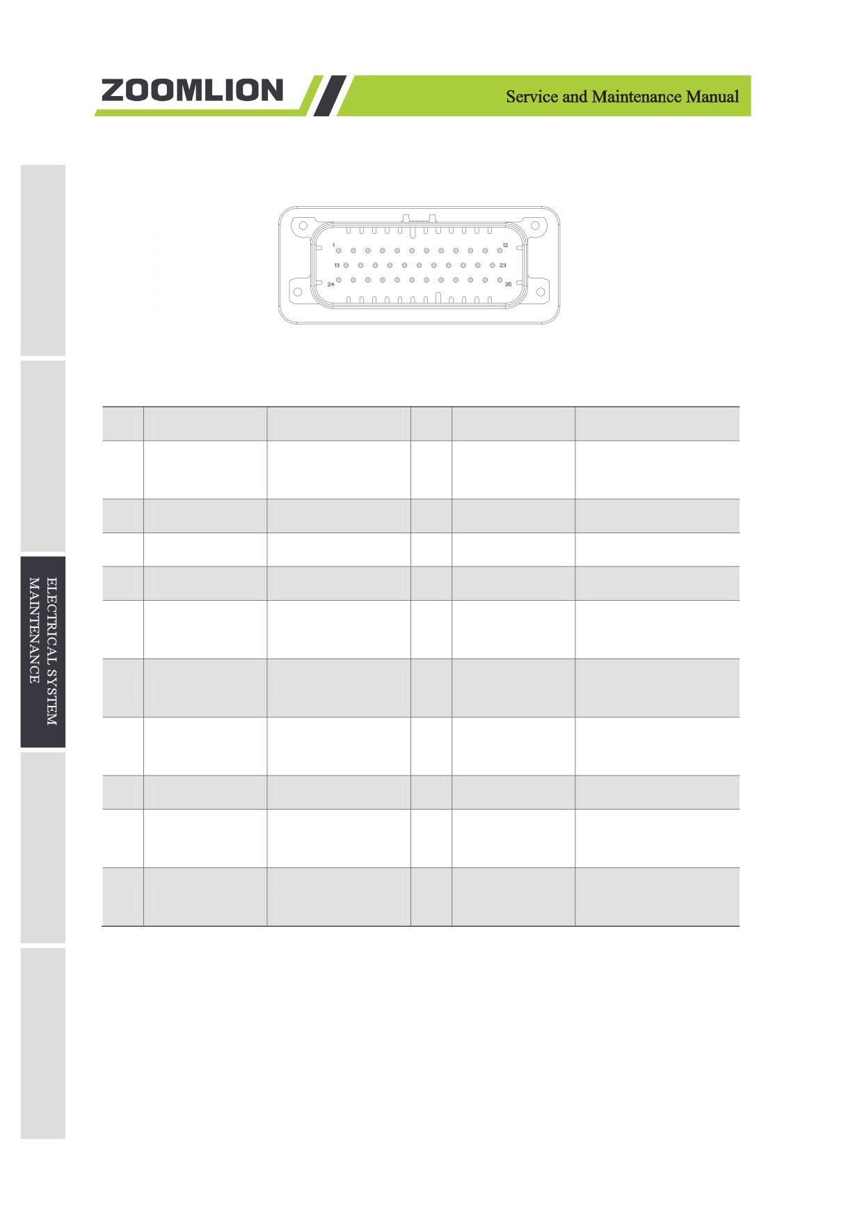
3.1.3 ECU pin definition
Figure 3-1 35 pin interface
Table 3-3 ECU 35 pin interface definition
Pin
Type
Function
Pin
Type
Function
Chassis elevating
1
Input
2
Input
Reserve
control switch
3
Output
Reserve
4
Power
Valve-driven power
5
Power
Valve-driven power
6
Output
Lifting valve control
7
Output
Forward control
8
Output
Pump motor enable
Pump motor speed
Left brake condition
9
Output
10
Input
control
check
Chassis lowering
11
Input
Reserve
12
Input
control switch
PCU communication
13
Communication
14
Input
Chassis key switch
+
15
Power
GND
16
Input
Angle sensor
Lowering valve 1
17
Input
Brake condition
18
Output
control
Left turn valve
19
Output
20
Output
Horn control
control
3-14
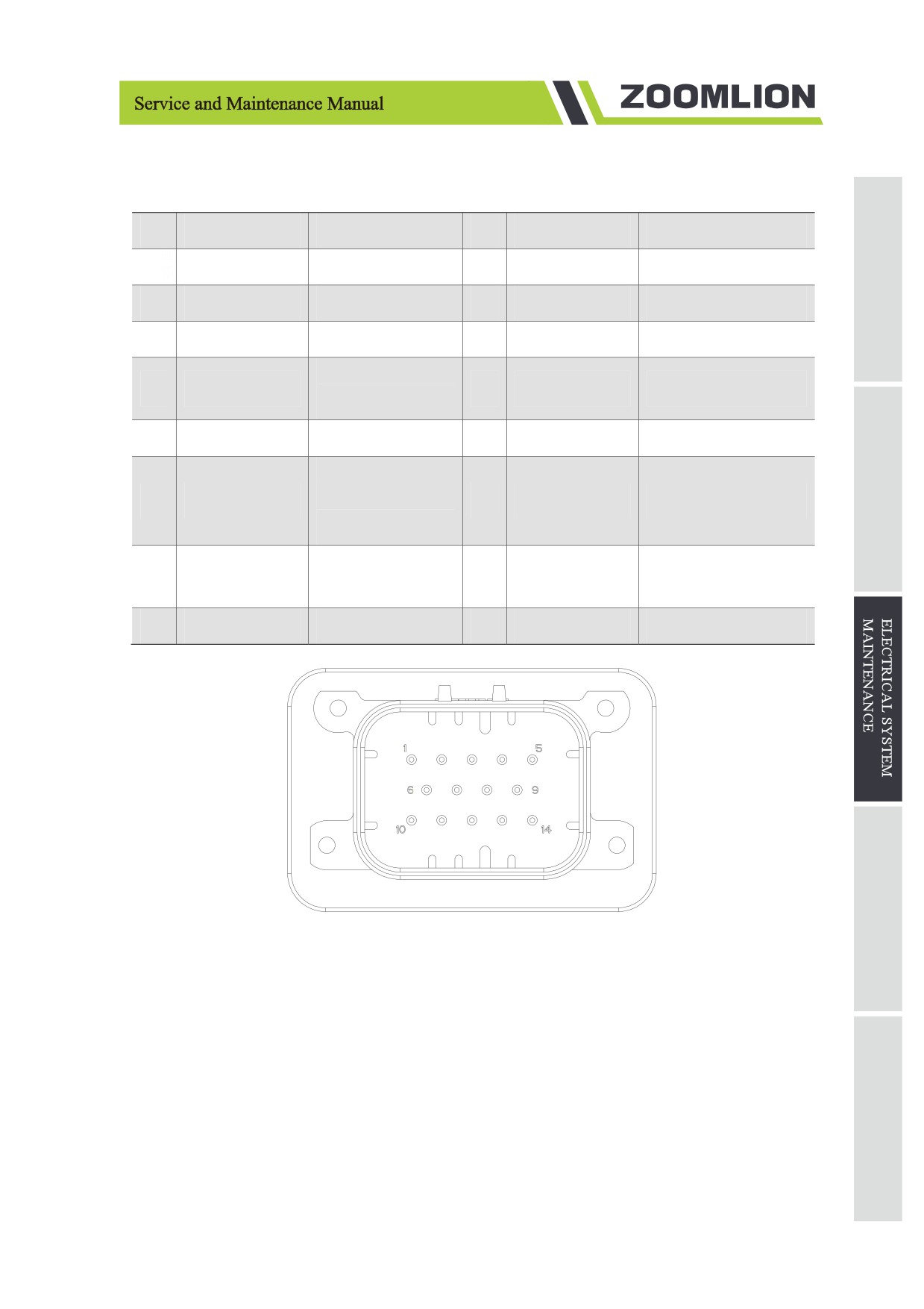
Table 3-3 ECU 35 pin interface definition
Pin
Type
Function
Pin
Type
Function
21
Output
Buzzer control
22
Input
Pothole switch
23
Input
Up limit switch
24
Communication
PCU communication -
25
Power
Working power
26
Input
Reserve
Drive motor speed
27
Output
28
Input
Driver fault code
control
29
Output
Backward control
30
Output
Right turn valve control
Parallel valve
31
Output
control/ Drive motor
32
Output
Brake valve control
enable
Right brake
33
Input
34
Input
Tilt switch
condition check
35
Input
Down limit switch
Figure 3-2 14 pin interface
3-15
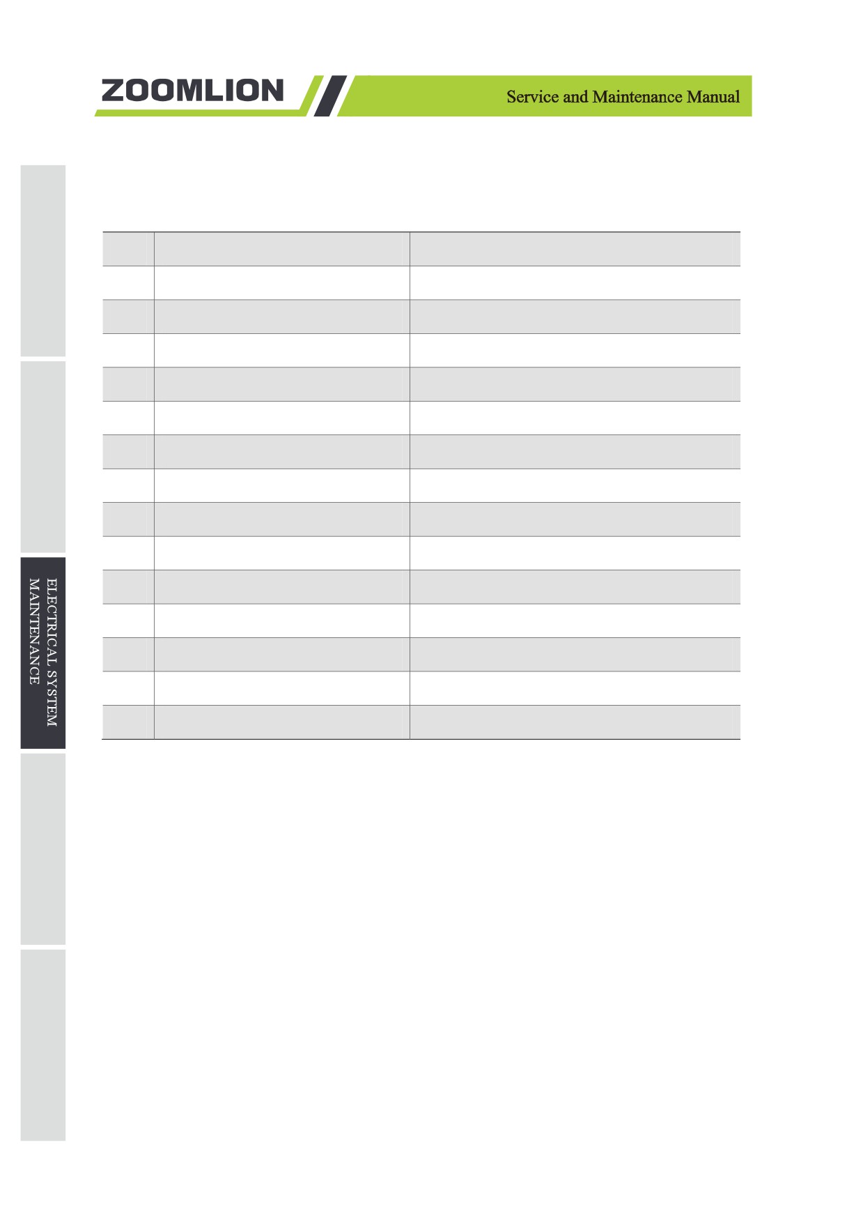
Table 3-4 ECU 14 pin interface definition
Pin
Type
Function
1
Output
Alarm control
2
Input
Reserve
3
Output
Reserve
4
Communication
GPS Communication CANH
5
Communication
GPS Communication CANL
6
Input
Pressure sensor signal 1
7
Input
Pressure sensor signal 2
8
Output
Reserve
9
Output
Reserve
10
Output
Reserve
11
Input
Reserve
12
Input
Reserve
13
Input
Reserve
14
Output
Lowering valve 2 control
3-16
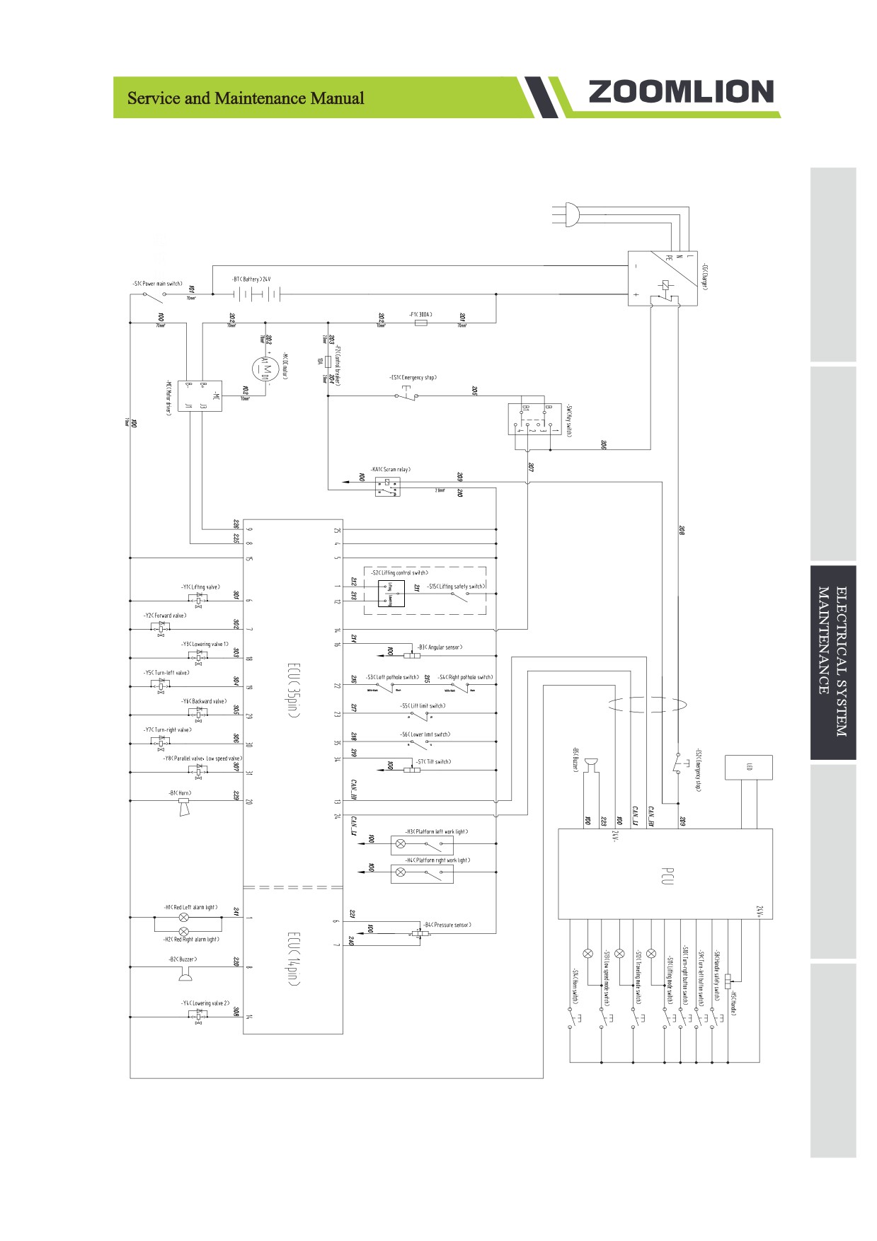
3.1.4 Electrical schematic
Figure 3-3 ZS4555HD/ZS4045HD/ZS3246HD Electrical schematic
3-17
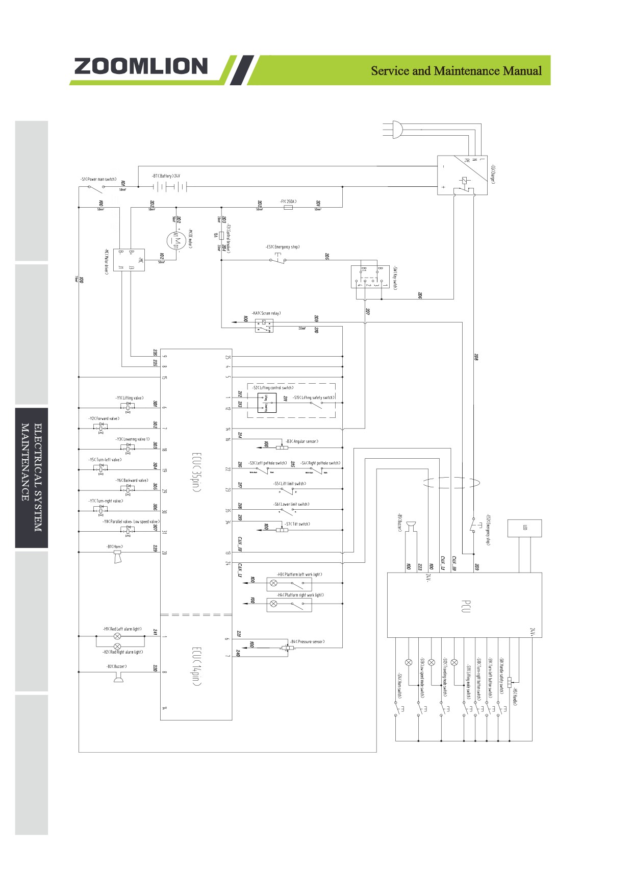
Figure 3-4 ZS2632HD/ZS2032HD Electrical schematic
3-18
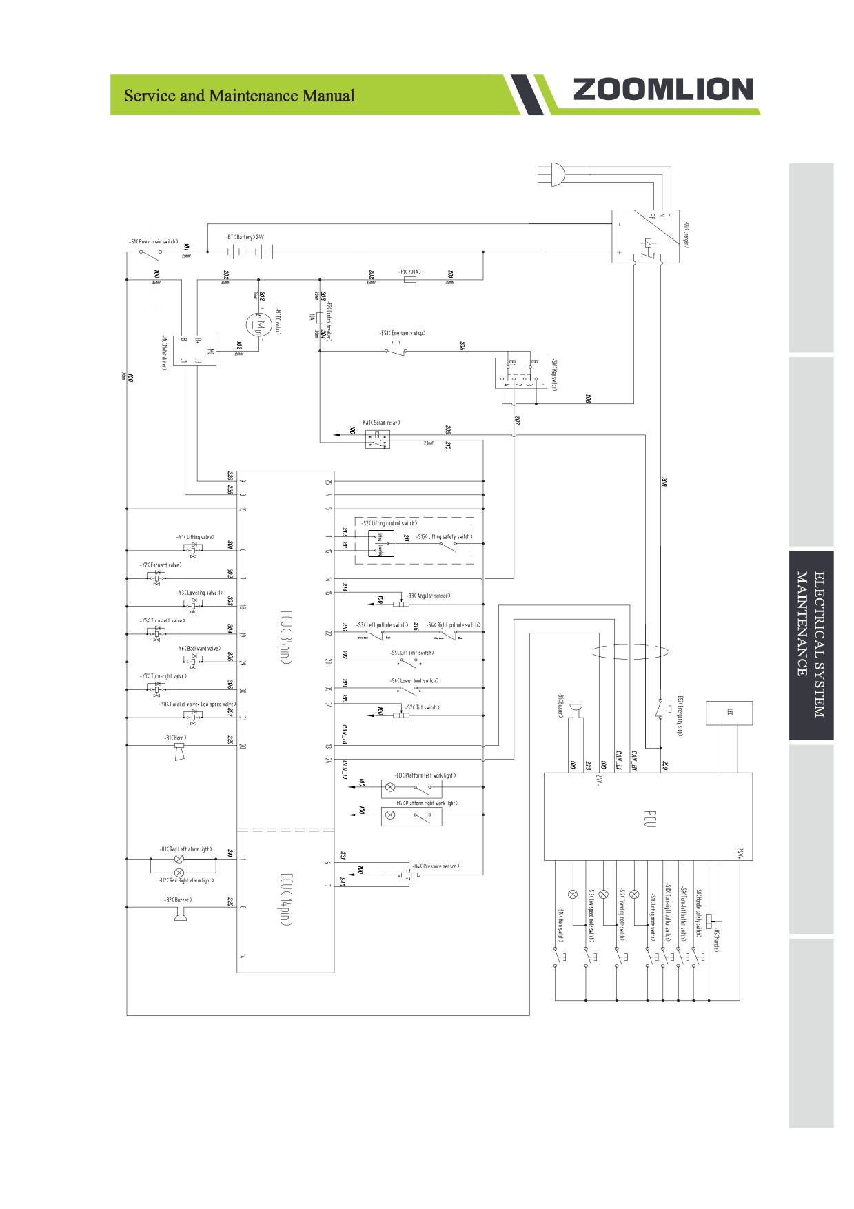
Figure 3-5 ZS1930HD Electrical schematic
3-19
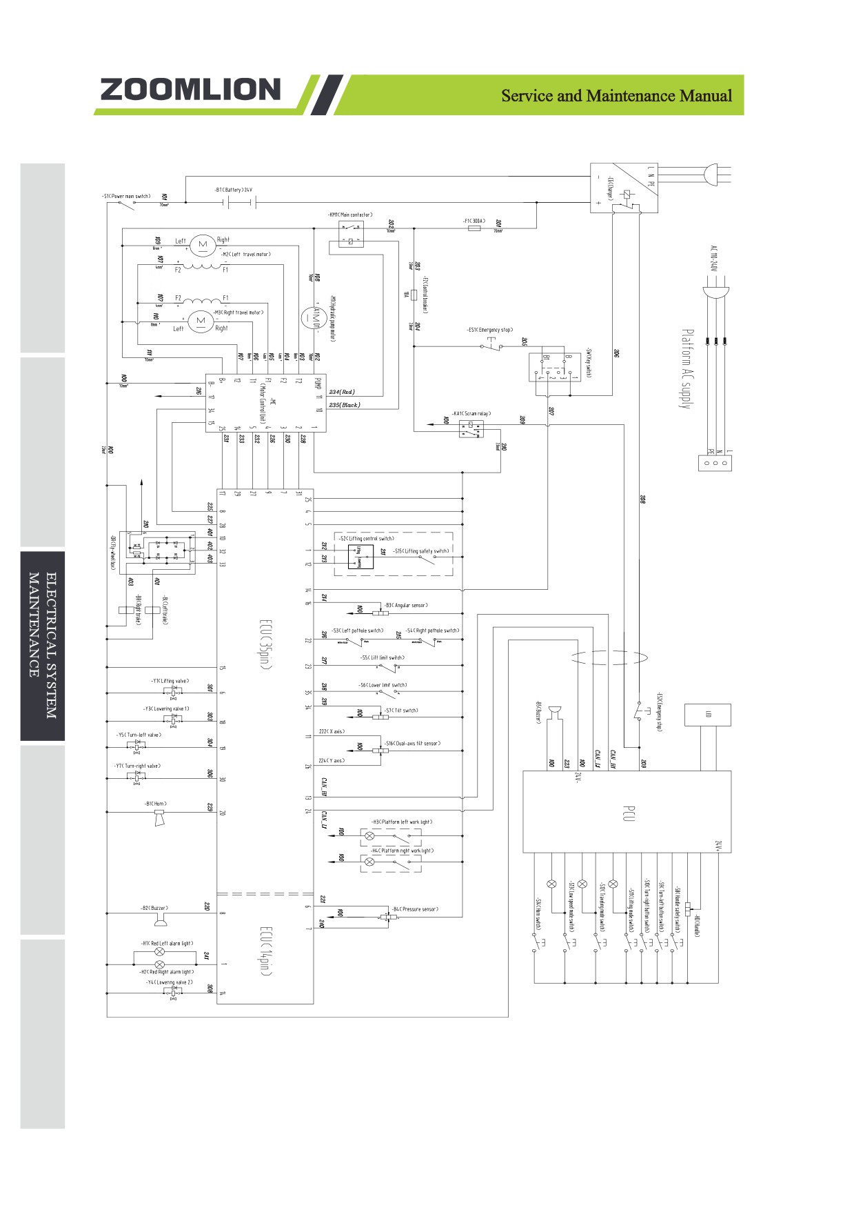
Figure 3-6 ZS4555DC/ZS4045DC/ZS3246DC Electrical schematic
3-20
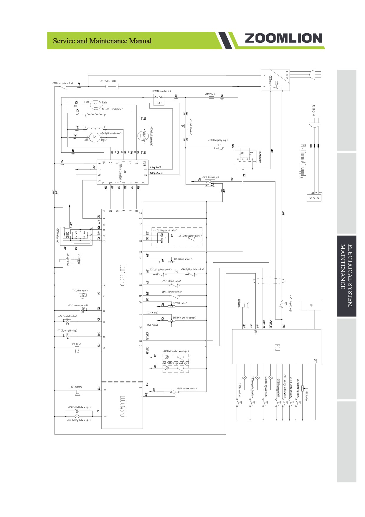
Figure 3-7 ZS2632DC/ZS2032DC Electrical schematic
3-21
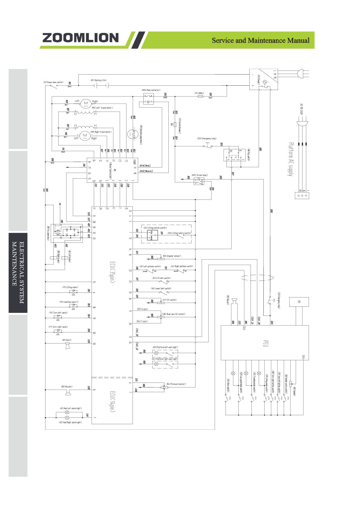
Figure 3-8 ZS1930DC Electrical schematic
3-22
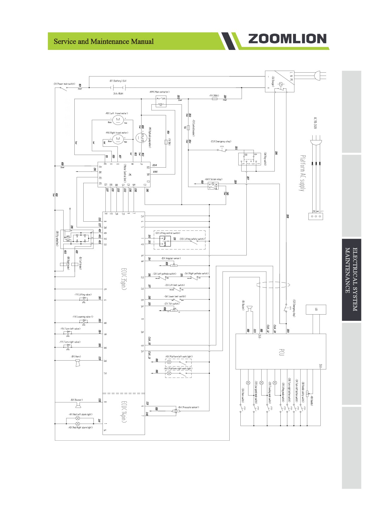
Figure 3-9 ZS1530DC Electrical schematic
3-23
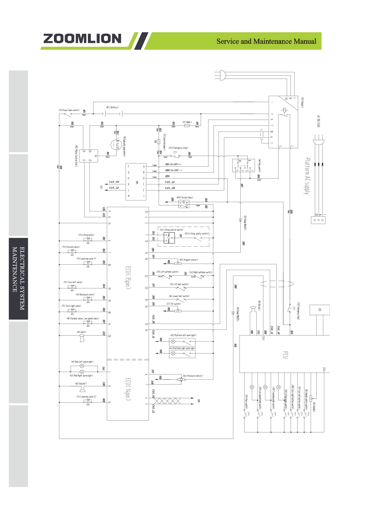
Figure 3-10 ZS4555HD-Li/ZS4045HD-Li/ZS3246HD-Li Electrical schematic
3-24
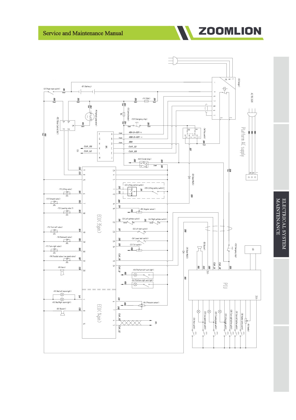
Figure 3-11 ZS2632HD-Li/ZS2032HD-Li Electrical schematic
3-25
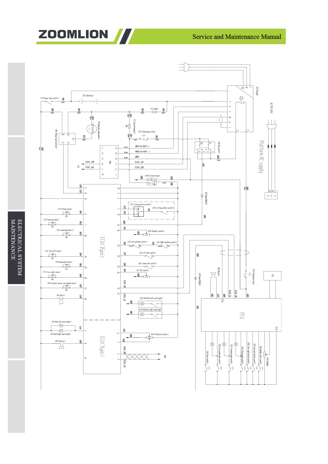
Figure 3-12 ZS1930HD-Li Electrical schematic
3-26
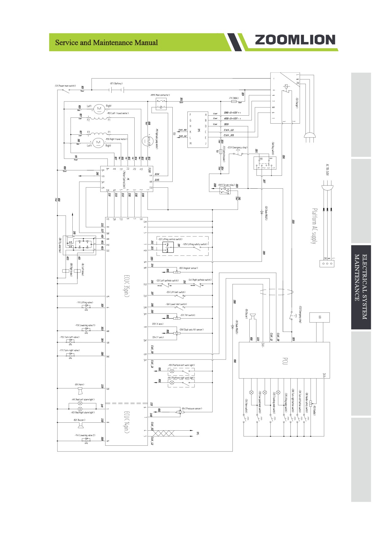
Figure 3-13 ZS4555DC-Li/ZS4045DC-Li/ZS3246DC-Li Electrical schematic
3-27
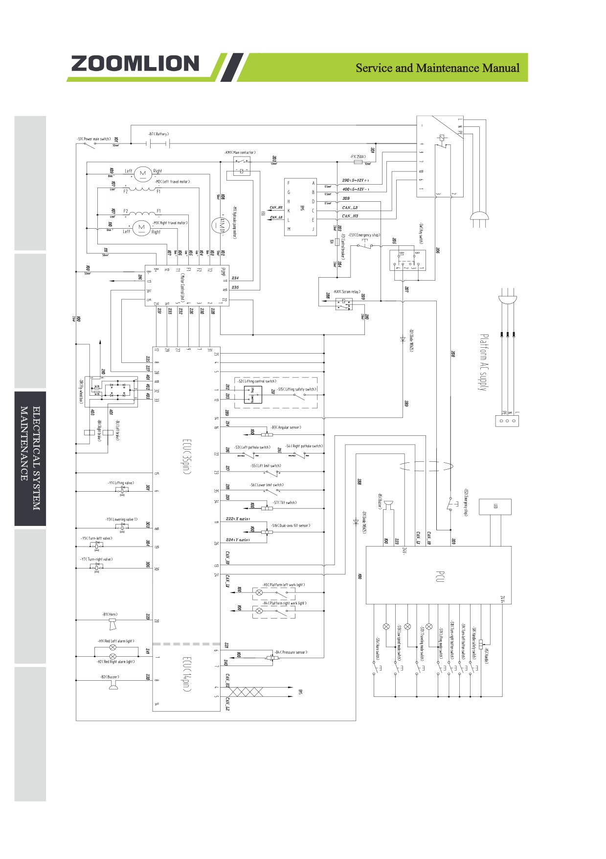
Figure 3-14 ZS2632DC-Li/ZS2032DC-Li Electrical schematic
3-28
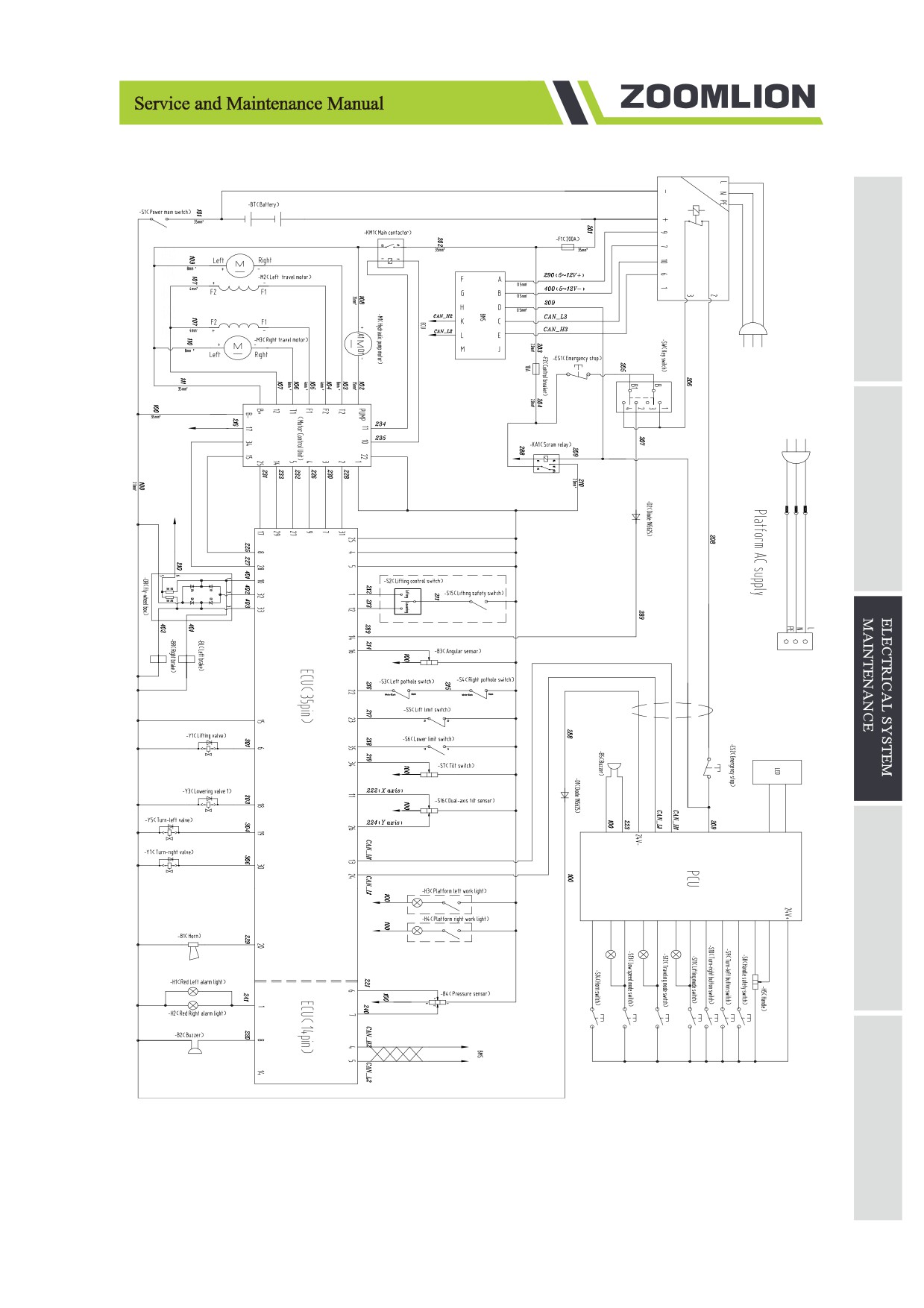
Figure 3-15 ZS1930DC-Li Electrical schematic
3-29
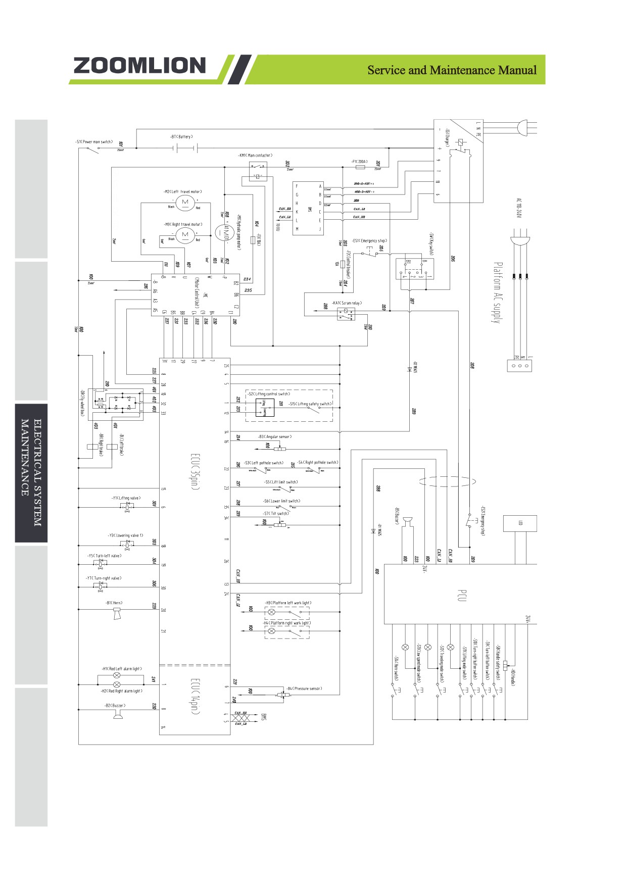
Figure 3-16 ZS1530DC-Li Electrical schematic
3-30