Zoomlion Scissor lift ZS4555HD, ZS4045HD, ZS3246HD, ZS2632HD, ZS2032HD, ZS1930HD, ZS1530DC. Service and Maintenance Manual - page 1
Service and Maintenance Manual
ZOOMLION
ZS4555HD/ZS4555DC/ZS4555HD-Li/ZS4555DC-Li/
ZS4045HD/ZS4045DC/ZS4045HD-Li/ZS4045DC-Li/
ZS3246HD/ZS3246DC/ZS3246HD-Li/ZS3246DC-Li/
ZS2632HD/ZS2632DC/ZS2632HD-Li/ZS2632DC-Li/
ZS2032HD/ZS2032DC/ZS2032HD-Li/ZS2032DC-Li/
ZS1930HD/ZS1930DC/ZS1930HD-Li/ZS1930DC-Li/
ZS1530DC/ZS1530DC-Li
Service and Maintenance Manual
July 2020 Version A
Foreword
The Service and Maintenance Manual applies to the scissor lift series.
This manual describes proper inspection, servicing and maintenance. Users must fully understand and
apply the contents described in this manual to maximize the performance and ensure the long-term safe
and efficient use.
The manual includes the structure and schematic diagram of the main components. If it is necessary to
repair and replace the components, the material code of the required replacement parts can be found in
Parts Manual.
This manual should be considered a permanent part of your machine and should remain the machine at
all times.
Do not repair the parts marked with professional maintenance. Zoomlion AWP Machinery
Company does not take the consequence for wrong maintenance.
The highest criterion users must keep in mind is:Safety first! Pay special attention to the safety
control device for regular inspection. Do not operate the machine when the safety device fails or
working abnormally. Do not modify the structure or add additional parts for more functions.
Otherwise, you will be responsible for any personal injury or damage caused by the unauthorized
modification.
The warranty period for the aerial work platform is as specified in this Service and Maintenance
Manual. When maintenance is required, our company provides on-site service or please go to our
designated maintenance point for maintenance.
Our company reserves the right to continually revise the contents of this manual with technical
improvements. Any changes are subject to change without notice. Some of the pictures in this
manual may not match the actual product due to design improvement, etc., but it does not affect
your use. The product status is subject to the actual product.
I
Foreword
Symbols and their description
Danger indicates an imminently dangerous situation. If not avoided, will result in death or serious
injury.
Warning indicates a potential hazardous situation. If not avoided, will result in death or serious
injury.
Caution indicates a potential hazardous situation. If not avoided, will result in minor or moderate
injury.
II
Contents
Foreword
I
Content
III
SECTION 1 MAINTENANCE SAFETY INSTRUCTION
1-1
1.1 Maintenance Cycle Instruction
1-1
1.2 User Responsibility
1-1
1.3 Service Center Obligation
1-1
1.4 Disclaimer
1-2
SECTION 2 MAINTENANCE REQUIREMENTS
2-1
2.1 General
2-1
2.1.1 Maintenance purpose
2-1
2.2 Precautions
2-1
2.2.1 General precautions
2-1
2.2.2 Safety precautions
2-2
2.3 Pre-delivery Inspection
2-4
2.4 Maintenance Intervals Instrustion
2-4
2.5 Maintenance Schedule
2-5
2.6 Maintenance Inspection
2-8
2.6.1 Daily inspection
2-8
2.6.1.1 Check manual and decals
2-8
2.6.1.2 Pre-start inspection
2-8
2.6.1.3 Battery inspection
2-8
2.6.1.4 Check hydraulic oil level
2-9
2.6.1.5 Functional test
2-9
2.6.2 Maintenenca every month
2-10
2.6.2.1 Maintenance after 30 days
2-10
2.6.2.2 Lubricate steering knuckles
2-10
2.6.3 Maintenance every 3 months
2-10
2.6.3.1 Battery maintenance
2-10
2.6.3.2 Li-ion battery maintenance
2-13
2.6.3.3 Inspect electrical wiring
2-13
2.6.3.4 Inspect the tires and wheels
2-14
2.6.3.5 Inspect emergency stop function
2-15
2.6.3.6 Test key switch
2-16
III
Contents
2.6.3.7 Test the horn
2-16
2.6.3.8 Test the drive brakes
2-16
2.6.3.9 Test the top drive speed-stowed position
2-18
2.6.3.10 Test the drive speed-raised position
2-18
2.6.3.11 Test slow drive speed-stowed position
2-19
2.6.3.12 Hydraulic oil analysis
2-20
2.6.3.13 Inspect hydraulic oil tank cap venting system
2-20
2.6.3.14 Inspect tray latch components
2-20
2.6.3.15 Inspect down limit switch, level sensor and pothole limit switch. 2-20
2.6.3.16 Inspect up limit switch
2-21
2.6.4 Maintenance every 6 months
2-22
2.6.4.1 Inspect platform overload system
2-22
2.6.4.2 Replace the hydraulic tank venting cap
2-23
2.6.4.3 Replace hydraulic filters
2-23
2.6.5 Maintenance every year
2-23
2.6.6 Maintenance every 24 months
2-25
SECTION 3 TRICAL SYSTEM MAINTENANCE
3-1
3.1 Electrical System Troubles shooting
3-1
3.1.1 Fault code
3-1
3.1.2 Troubles shooting method
3-6
3.1.3 ECU pin definition
3-14
3.1.4 Electrical schematic
3-17
SECTION 4 HYDRAULIC SYSTEM MAINTENANCE
4-1
4.1 Inspection and Maintenance of Hydraulic System
4-1
4.1.1 Routine inspection of hydraulic system
4-1
4.1.2 Hydraulic oil tank
4-3
4.1.2.1 Inspection of hydraulic oil tank
4-3
4.1.2.2 Replace return oil filter
4-4
4.1.2.3 Replace exhaust hydraulic oil
4-5
4.1.2.4 Replace hydraulic oil
4-5
4.1.3 Hydraulic system air exhaust
4-6
4.1.4 Check hydraulic system line breakage
4-6
4.1.5 Hydraulic cylinder inspection
4-6
IV
Contents
4.1.6 Hydraulic hose inspection
4-7
4.1.7 Hydraulic valves
4-10
4.1.8 Hydraulic system pressure adjusting
4-16
4.1.8.1 Main pressure adjusting
4-16
4.1.8.2 Steering pressure adjusting
4-17
4.1.8.3 Lifting pressure adjusting
4-19
4.1.9 Hydraulic schematics
4-21
SECTION 5 COMMON FAULTS ANALYSIS
5-1
5.1 Hydraulic System Fault
5-1
5.2 Electrical System Fault
5-5
V
SECTION 1 MAINTENANCE SAFETY INSTRUCTION
Your proper maintenance is an important prerequisite for the use of the aerial work platform. Read and
understand this manual before attempting to any maintenance procedure. Conduct daily and regular
maintenance in accordance with the contents and requirements of this manual. Zoomlion's marketing
network throughout the world will provide you with professional consulting, maintenance and repair
services. This section introduces the scope of responsibility for maintenance.
1.1 Maintenance Cycle Instruction
Daily maintenance is conducted everyday or every week, and maintenance with a period of more than
one week is called regular maintenance. Maintenance work must be cycled on a regular basis and strictly
follow the technical requirements and techniques in this manual.
1.2 User Responsibility
Please conduct daily and regular maintenance in accordance with the contents and requirements of this
manual for good performance and personal safety. The responsibilities you must perform include but are
not limited to:
a) Operate and use the machine in accordance with the Maintenance Manual.
b) Conduct daily and regular maintenance in accordance with the contents and requirements of this
manual, professional technical maintenance must be performed at an authorized Zoomlion dealer
service center.
c) Use formal Zoomlion accessories.
d) When the aerial work platform fails, the information should be promptly and accurately fed back to
the designated service center.
e) Please provide workplace, equipment and tools for on-site service.
f)
When your equipment is transferred, you must promptly inform the service centers that are
transferred to and from the place of departure.
1.3 Service Center Obligation
Service centers are dedicated to providing you with a full range of after-sales services, including:
a) Professional product technical support.
b) Provide formal Zoomlion accessories.
c) Warranty service under warranty agreement.
d) Perform major abnormal faults and incident handling.
e) Provide equipment maintenance services.
1-1
1.4 Disclaimer
Zoomlion does not assume any responsibility for direct or indirect losses caused by the following actions:
a) Wrong operations or applications.
b) Unauthorized modification and parameter adjustment of the machine.
c) Do not use Zoomlion's original accessories and dedicated oils.
d) Maintenance is not performed in accordance with the contents and requirements of this manual.
1-2
SECTION 2 MAINTENANCE REQUIREMENTS
2.1 General
a) Perform necessary oil inspection and replacement. Conduct regular inspections to ensure that
components are in good condition.
b) Require appropriate equipment for maintenance and repair, and obey relevant rules and instructions
in Operator's manual.
c) If the safety equipment is removed during maintenance, reinstall the safety equipment and inspect it
immediately after the maintenance work is completed.
d) Ensure that fuel, lubricants, and replaced parts are safely disposed of in accordance with
environmental regulations.
2.1.1 Maintenance purpose
a) Prepare for operation.
b) Maintain stable performance.
c) Prevent downtime.
d) Maintain use value.
e) Reduce maintenance cost.
2.2 Precautions
2.2.1 General precautions
a) Wear working clothes for maintenance work.
b) Machine parked on a firm, level surface.
c) Prevent dust and dirt from entering the system when inspecting or servicing the hydraulic system.
d) If you find any items that require immediate repair and adjustment, perform maintenance
immediately.
e) Contact local Zoomlion service center for repairing.
f)
Please use the accessories and grease specified by our company for good performance.
g) Timely replacement of consumables, such as filter element to prevent failures due to delays.
h) Please contact our local office for any difficult problems identified during inspection or maintenance.
2-1
2.2.2 Safety precautions
a) Perform all locks, turn the power switch to off position and remove the switch keys during machine
inspection and maintenance.
If not comply with the rules, could result in serious injury or death.
a) Set the warning sign during maintenance.
Set DO NOT START, IN MAINTENANCE warning sign during maintenance.
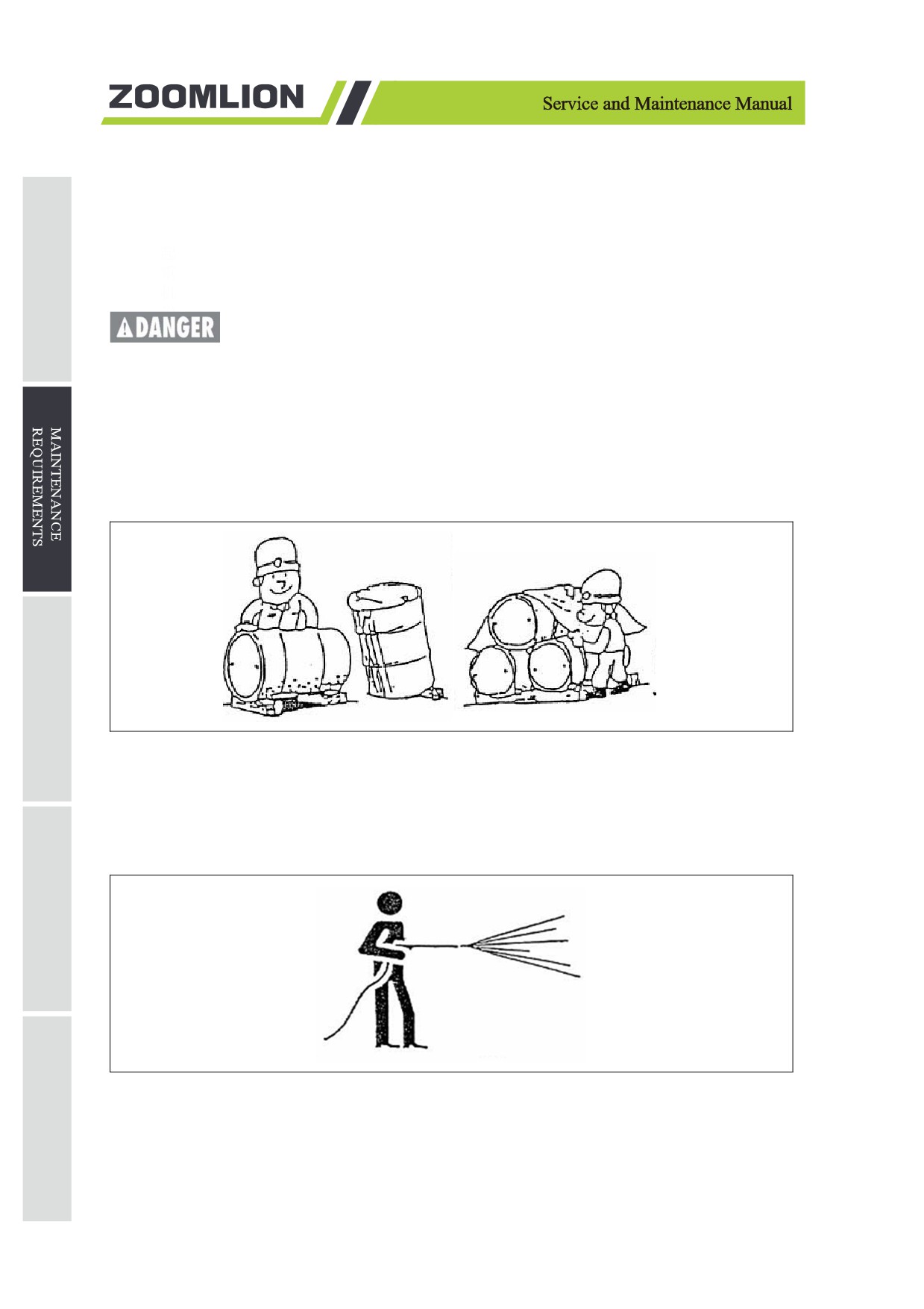
b) Use clean grease.
The room where grease is stored should be kept clean and no dust, water, etc. should enter the container.
Ensure that the grease used does not contain water.
Figure 2-1 Clean grease check
c) Keep the machine clean.
Clean the machine with clean water to find oil leaks, cracks, loose connections and other abnormalities.
Keep grease nipples, vents and dipsticks clean to prevent dust.
Figure 2-2 Clean the unit
2-2

Figure 2-3 DO NOT spray water at the joint
a) Do not spray water on electrical components and connectors while cleaning the machine.
b) Lubricate the steering knuckles after cleaning.
c) Clean the control panel with warm water containing detergent only. DO NOT use corrosive cleaning
agent.
d) Clean oil stain.
When filling or replacing fuel, hydraulic oil, grease, or replacing the filter element, oil may spill. Wipe
the spilled oil in time to prevent fire.
e) Check the discharged waste oil and old filter.
Check for metal chips or foreign objects when replacing the oil or filter element.
f)
Prevent dust intrusion.
The dismantled hydraulic tubing and hydraulics must be protected with a blockage or seal to prevent dust.
Figure 2-4 Dust prevention
g) Clean joint surface.
Removing the O-ring or other gasket, clean the sealing surface and replace with a new seal. Apply a thin
layer of oil to the seal when reassembling.
Pay attention to internal pressure. Remove the pressure before disassembling pipes, joints or other related
components with internal pressure, such as hydraulic systems, compressed air systems, etc.
2-3

Figure 2-5 Notice internal pressure
h) Clean waste oil.
1) Place the waste oil in a container and treated as industrial waste.
2) Maintenance and parts replacement must be implemented by trained professionals.
i)
Check the records.
Conduct and record regular inspections to learn the operation condition of the machine and components
(Inspection should be conducted in machine's first use or initial use after long-term suspension or after
repair).
2.3 Pre-delivery Inspection
It is the responsibility of the dealer to perform the Pre-delivery Preparation.
Pre-delivery Preparation is performed prior to each delivery. The inspection is designed to discover if
anything is apparently wrong with a machine before it is put into service.
A damaged or modified machine must never be used. If damaged or any variation from factory delivered
condition is discovered, the machine must be tagged and removed from service.
Repairs to the machine may only be made by a qualified service technician, according to the
manufacturer's specification. Scheduled maintenance inspections shall be performed by qualified service
technicians, according to the manufacturer's specifications and the requirements listed in the
responsibilities manual.
2.4 Maintenance Intervals Instructions
All maintenance work is done intermittently that the Intermittent period is the maintenance period.
Maintenance intervals are determined based on two aspects:
a) Certain running time of functional components (hours).
b) The Gregorian time (day, month, year) at which the machine is working and stored.
Maintenance intervals of Zoomlion Scissor Lifts are generally determined by the certain running time of
functional components, and the special content needs to be determined in the latter way.
2-4
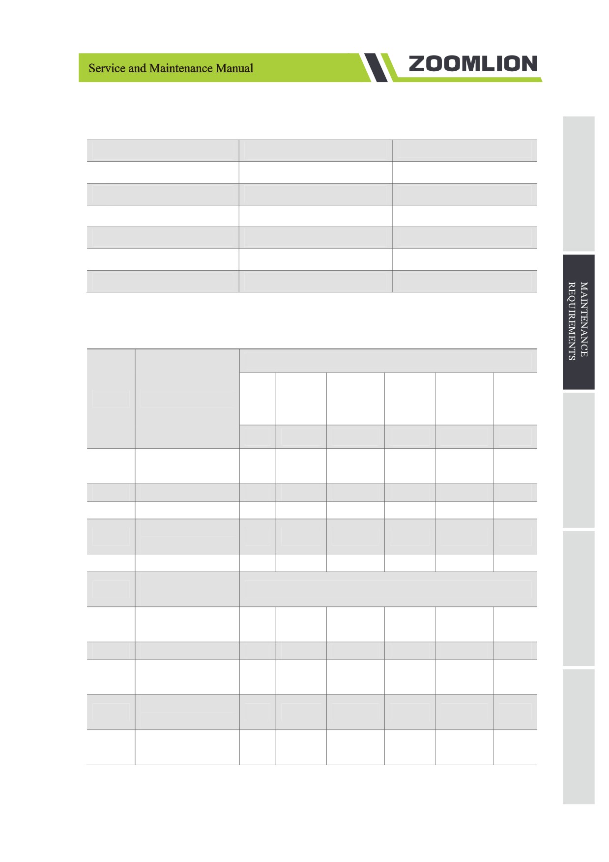
Table 2-1 Maintenance intervals
Maintenance Intervals
Running Time (hours)
Maintenance Intervals
Daily (D)
8
Before and after operation
Monthly (M1)
About 100
Once a month
Quarterly (M3)
About 250
Once every three months
Every 6 months (M6)
About 500
Once every six months
Annually (M12)
About 1,000
Once a year
Every two years (M24)
About 2,000
Once every 24 months
2.5 Maintenance Schedule
Table 2-2 Maintenance schedule
Maintenance
Every
Every 6
Items
Work Description
Daily
Monthly
Quarterly
Annually
two
months
years
D
M1
M3
M6
M12
M24
Check manual and
2.6.1.1
★
decals
2.6.1.2
Pre-start Inspection
★
2.6.1.3
Battery Inspection
★
Check hydraulic
2.6.1.4
★
oil level
2.6.1.5
Functional test
★
Maintenance after 30
2.6.2.1
▲ After using for the first time for 30 days or 50 hours
days
Lubricating steering
2.6.2.2
★
knuckles
2.6.3.1
Battery maintenance
★
Li-ion battery
2.6.3.2
★
maintenance
Inspect electrical
2.6.3.3
★
wire
Inspect the tires and
2.6.3.4
★
wheels
2-5
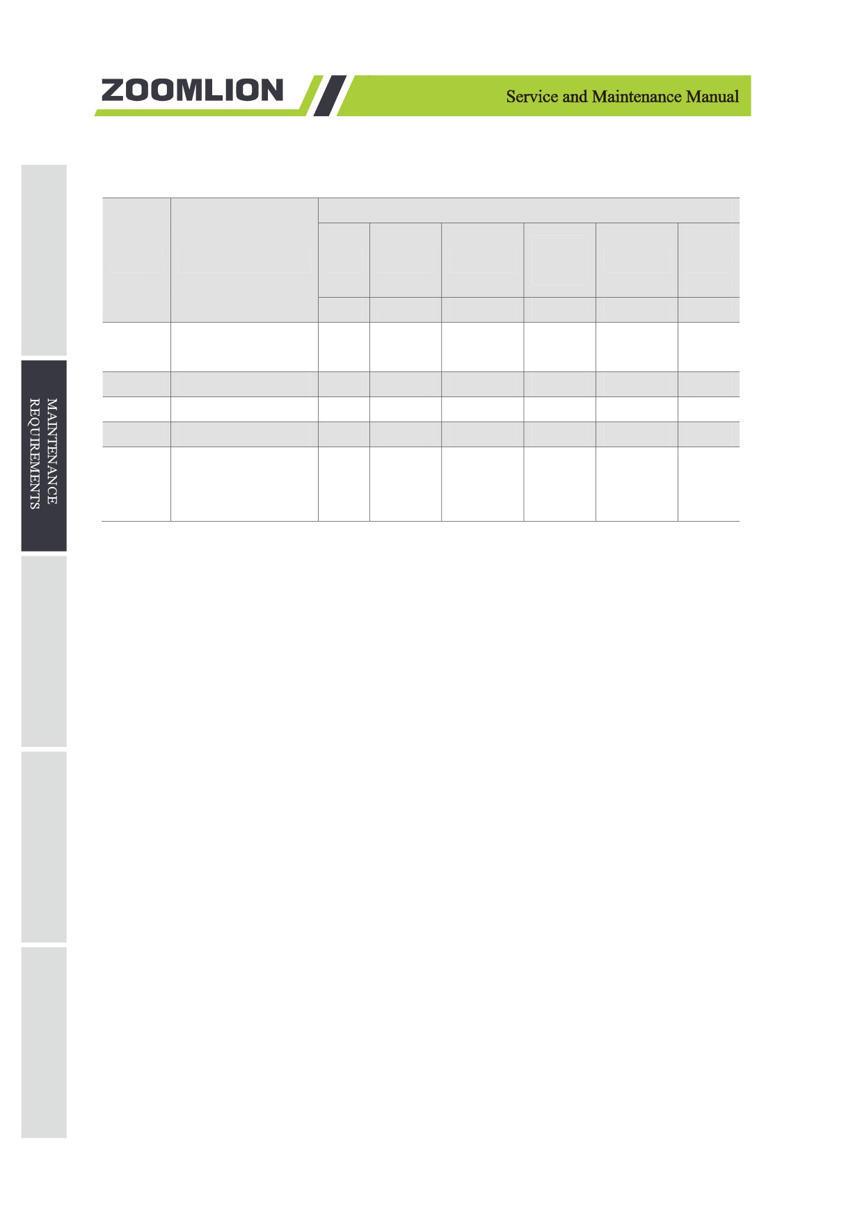
Table 2-2 Maintenance schedule
Maintenance
Every
Every 6
Items
Work Description
Daily
Monthly
Quarterly
Annually
two
months
years
D
M1
M3
M6
M12
M24
Inspect emergency
2.6.3.5
★
stop function
2.6.3.6
Test key switch
★
2.6.3.7
Test the Horn
★
2.6.3.8
Test the drive brakes
★
Test the top drive
2.6.3.9
speed - stowed
★
position
Instruction: ★ Regular maintenance intervals
▲ Initial maintenance time
2-6
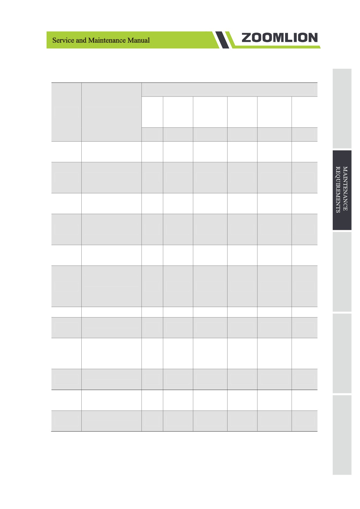
Table 2-2 Maintenance schedule
Maintenance
Every
Every 6
Items
Work Description
Daily
Monthly
Quarterly
Annually
two
months
years
D
M1
M3
M6
M12
M24
Test the drive speed
2.6.3.10
★
(raised)
Test slow drive
2.6.3.11
speed - stowed
★
position
Hydraulic oil
2.6.3.12
★
analysis
Inspect hydraulic oil
2.6.3.13
tank cap venting
★
system
Inspect tray latch
2.6.3.14
★
components
Inspect down limit
switch,level sensor
2.6.3.15
★
and pothole limit
switch
2.6.3.16
Test up limit switch
★
Test platform
2.6.4.1
★
overload system
Replace the
2.6.4.2
hydraulic tank
★
venting cap.
Replace hydraulic
2.6.4.3
★
filters
Maintenance every
2.6.5
★
year
Maintenance every
2.6.6
★
24 months
Instruction: ★ Regular maintenance intervals
▲ Initial maintenance time
2-7
2.6 Maintenance Inspection
2.6.1 Daily inspection
2.6.1.1 Check manual and decals
Ensuring that the operation and maintenance manual is in good condition. Each unit is stored with
operation and maintenance manuals. Manuals should be stored in the platform container. Manuals with
illegible or missing pages do not provide sufficient information to ensure safe operation.
Ensure that all safety decals are intact. Decal alerts the operator to the safety hazard of using the machine.
It also provides operational and maintenance information to the user.Blurred decals will not serve as a
warning and may result in a dangerous operating environment.
a) Check and ensure that the operation and maintenance manual is in the storage box of the platform.
b) Ensure that there is no illegible or missing pages.
1) Result: the manual matches the model, all manuals are legible and there are no missing pages.
2) Result: the manual does not match the model, or the manual is illegible or there are missing
pages.
3) Stop using the machine before the manual is replaced.
c) Check the Decal Inspection section in manual. Ensure the decal is legible and intact.
1) Result: all decals are clear and complete.
2) Result: decal is missing, illegible or damaged.Stop using the machine before the manual is
replaced.
d) Put it back in the storage box after using the manual.
e) Reminder: if need to replace the manual or label, please contact Zoomlion or Zoomlion dealer.
2.6.1.2 Pre-start inspection
It is important to implement pre-start inspection for safety operation. The pre-operation check is done
visually before the machine is running. This inspection is used to find out if there are obvious problems
with the machine before the functional test. It could be used to decide whether to perform routine
maintenance procedures.
2.6.1.3 Battery inspection
Proper battery condition is essential to good machine performance and safety operation. Improper fluid
level or damaged cables and connections can result in component damage and hazardous conditions.
2-8
Machines with sealed or maintenance-free batteries are not required for this check.
a) Contact with electrically charged circuits could result in death or serious injury. Remove all rings,
watches or other jewelry.
b) Batteries fluid is highly corrosive. Avoid spilling or contacting battery acid. Neutralize battery acid
spills with baking soda and water.
Fully charge the battery before performing the following inspections.
a) Only qualified riggers should rig the machine.
b) Only certified crane operators should lift the machine and only in accordance with the applicable
crane regulations.
c) Be sure that the battery retainers are tight.
d) Remove the battery vent caps.
e) Check the battery acid level. If needed, replenish with distilled water from the battery fill hole. Do
not overfill.
f)
Install the vent caps.
2.6.1.4 Check hydraulic oil level
Proper hydraulic fluid level is very important for operating the machine. Improper hydraulic oil level
could damage hydraulic components. Through the daily inspection, the inspector can determine the
change of the hydraulic oil levels that can indicate problems with the hydraulic system.
Conduct the inspection in stowed position.
a) Visually inspect the hydraulic oil level on the side of the hydraulic tank.
b) Result: the hydraulic oil level should be at the mark of the fuel tank.
c) Add oil as needed. Do not overfill.
2.6.1.5 Functional test
Completing the functional test is very important for the safe operation. The functional test is used to find
out whether the machine has functional defects before the machine works, and the defective machine
cannot be used. Once a functional defect is discovered, mark the machine immediately and stop using it.
2-9
A complete inspection procedure can be found in the Functional Test section of this manual.
2.6.2 Maintenance every month
2.6.2.1 Maintenance after 30 days
30-day maintenance is a one-time maintenance after the first 30 days or 50 hours of machine operation.
Continue the scheduled maintenance after this one-time maintenance.
Perform the following maintenance:
a) Tires and hubs.
b) Replace the hydraulic filter.
2.6.2.2 Lubricate steering knuckles
Conduct this inspection every 100 hours.
a) Regular lubrication of steering knuckle is essential for good machine performance and service life.
Long-term use of knuckles that are not effectively lubricated will result in damage to the parts.
b) Open the lid on the knuckle and find the greased hole at the top of the knuckle. Fill enough grease
into the knuckle till the grease covering the bearing.
c) Replace the cover and repeat the above process for the other steering knuckles.Grease specifications:
use 3 # general lithium-based grease.
2.6.3 Maintenance every 3 months
2.6.3.1 Battery maintenance
This inspection is conducted every 250 hours or quarter, whichever comes first.
Proper battery condition is essential for good machine performance and safety operation. Improper fluid
levels or damaged cables and connections can result in component damage and hazardous conditions.
a) Contact with electrically charged circuits could result in death or serious injury. Remove all rings,
watches or other jewelry.
b) Batteries fluid is highly corrosive. Avoid spilling or contacting battery acid. Neutralize battery acid
spills with baking soda and water.
c) Put on protective clothing and eye wear.
d) Release the battery pack latch and rotate the battery pack out and away from the chassis.
e) Be sure that the battery cable connections are free of corrosion.
f)
Add terminal protectors and a corrosion preventative sealant will help eliminate corrosion on the
battery terminals and cables.
2-10
g)
Be sure that the battery retainers and cable connections are tight.
h)
Fully charge the batteries and allow the batteries to rest 24 hours.
i)
Remove the battery vent caps and check the specific gravity of each battery cell with a hydrometer.
j)
Check the ambient air temperature and adjust the specific gravity for each as follows:
1) Add 0.004 from the reading of each cell for every 5.5℃/ 42℉ above 26.7℃/ 80℉.
2) Subtract 0.004 from the reading of each cell for every 5.5℃/ 42℉ below 26.7℃/ 80℉.
3) Result: all battery cells display an adjusted specific gravity of 1.277 or higher. The battery is
fully charged. Proceed to step k.
4) Result: one or more battery cells display a specific gravity of 1.217 or below. Proceed to dtep h.
k)
Perform a equalizing charge OR fully charge the battery(s). Allow the battery(s) to rest at least 6
hours.
l)
Remove the battery vent caps and check the specific gravity of each battery cell with a hydrometer.
m)
Check the ambient air temperature and adjust the specific gravity for each as follows:
1) Add 0.004 from the reading of each cell for every 5.5℃/ 42℉ above 26.7℃/ 80℉.
2) Subtract 0.004 from the reading of each cell for every 5.5℃/ 42℉ below 26.7℃/ 80℉.
3) Result: all battery cells display an adjusted specific gravity of 1.277 or higher. The battery is
fully
4) charged. Proceed to step k).
5) Result: the difference in specific gravity readings between cells is greater than 0.1 OR the
specific
6) gravity of one or more cells is less than 1.217. Replace the battery.
n)
Check the battery acid level.If needed, replenish with distilled water to 3mm/0.04in below the bottom
of the battery fill tube. Do not overfill.
o)
Install the vent caps and neutralize any electrolyte that may have spilled.
p)
Verify that the batteries are wired correctly.
2-11
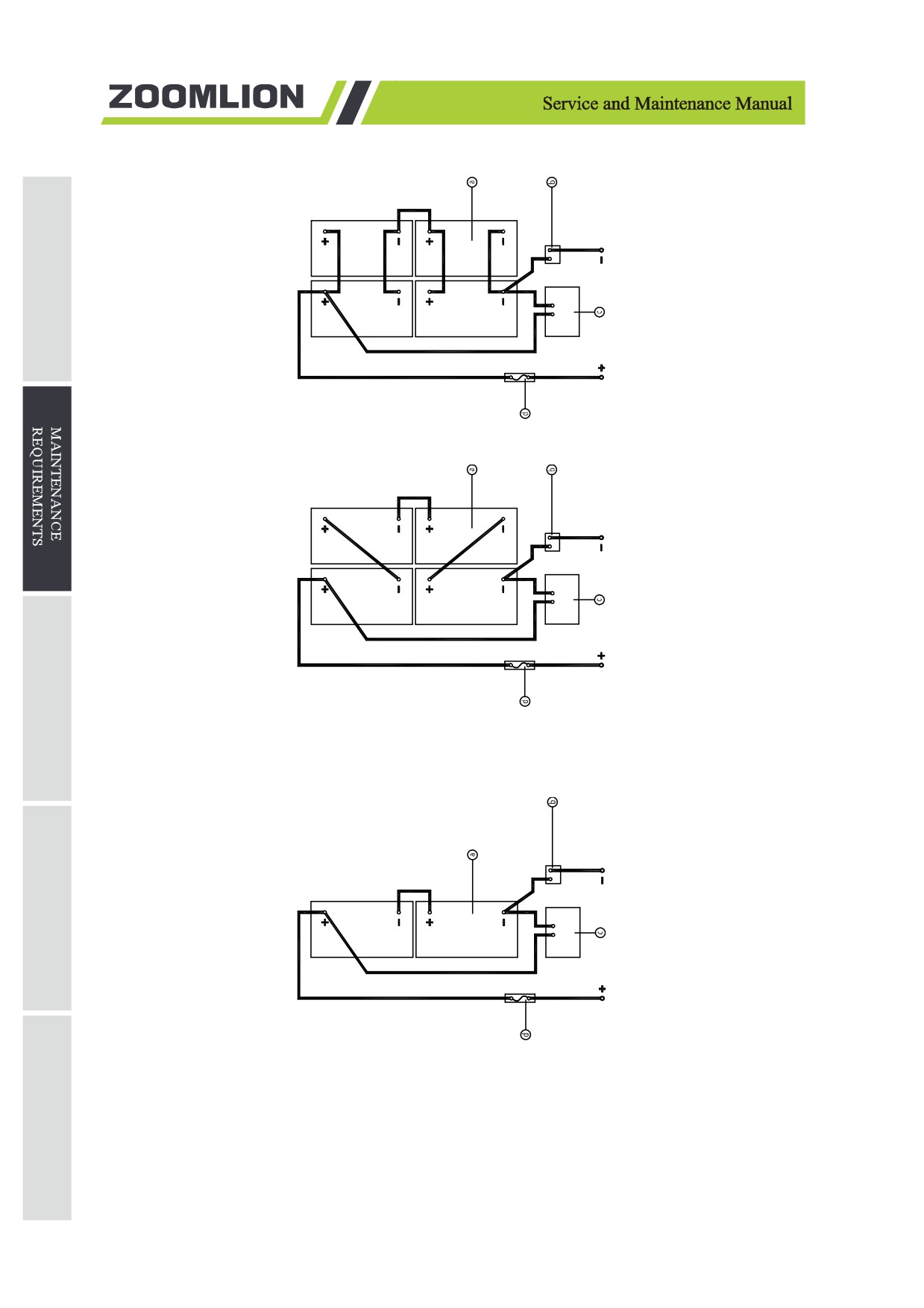
Figure 2-6 ZS4555HD/ZS4555DC/ZS4045HD/ZS4045DC Battery connections
Figure 2-7 ZS3246HD/ZS3246DC/ZS2632HD/ZS2632DC/ZS2032HD/ZS2032DC/
ZS1930HD/ZS1930DC Battery connections
Figure 2-8 ZS1530DC Battery connections
2-12
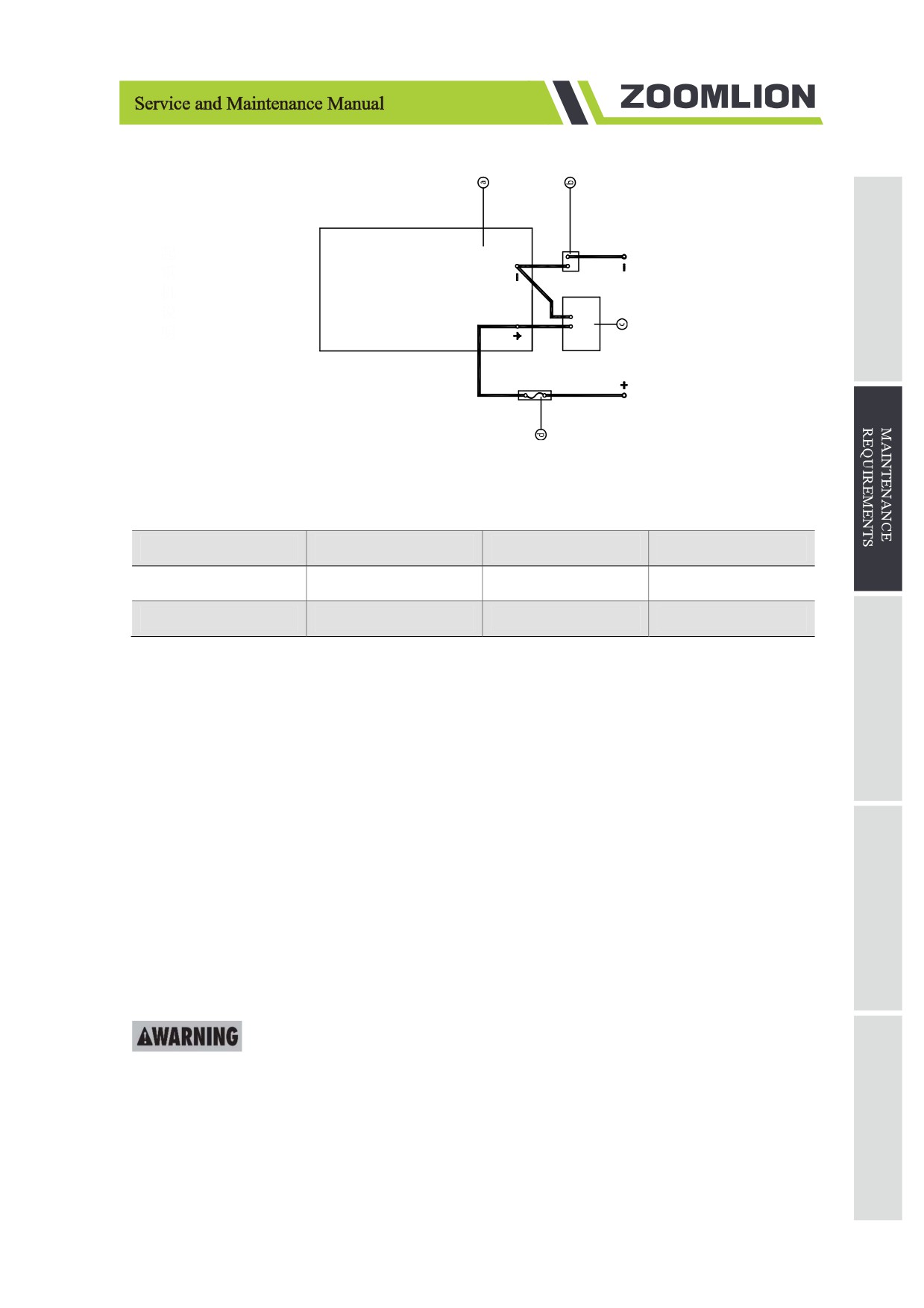
Figure 2-9 Li-ion Battery connections
Table 2-3 Code name
Code
Name
Code
Name
a
Battery/Li-ion battery
b
Main Switch
c
Charger
d
Fuse
q) Inspect the battery charger plug and pigtail for damage or excessive insulation wear. Replace as
required.
r)
Connect the battery charger to 110-240V 50/60 HZ AC power.
1) Result: charger operates. Charge the batteries.
2) Result: the charger's fault indicator flashes or displays a fault code. Check and correct the
charger input cable, as well as the battery and charger connections, make sure the charger is
operating properly and start charging the battery.
Consult Zoomlion after-sale service team for more relevant problems.
2.6.3.2 Li-ion battery maintenance
The battery system should not be used for a long time. It should be placed in a cool and dry environment
(temperature below 30℃/ 86℉ and humidity less than 90%), and it should be charged with a special
charger at least every three months.
The lithium battery should be charged in time when the voltage is too low, otherwise the battery
will be over-discharged and the machine cannot move normally.
2.6.3.3 Inspect electrical wiring
This inspection is conducted every 250 hours or quarter, whichever comes first.
2-13
Maintaining electrical wiring in good condition is essential to safe operation and good machine
performance. Failure to find and replace burnt, chafed, corroded or pinched wires could result in unsafe
operating conditions and may cause component damage.
Contact with electrically charged circuits could result in death or serious injury. Remove all rings,
watches and jewelry.
a) Inspect that if the ground wire under the chassis is missing or damaged.
b) Inspect the following areas for burnt, chafed, corroded pinched and loose wires:
1) Ground control box interior.
2) Hydraulic manifold wiring in hydraulic tray.
3) Battery wiring in battery tray.
4) Platform control box interior.
c) Turn the key switch to Platform Control and pull out the red Emergency Stop button to the on position
at both the ground and platform controls.
d) Raise the platform approximately 2.5m/8ft 2in from the ground.
e) Lift the safety arm, move the safety arm to the middle of the scissor bushing and rotate it down to
the vertical position.
f)
Lower the platform until the safety arm is in full contact with the bushing.
Keep hands away from the safety arm when lowering the platform.
a) Inspect the following areas for burnt, chafed, corroded pinched and loose wires:
1) Scissor arm wiring.
2) ECU to platform.
3) All wire harness connectors to platform control box.
b) Lift the platform, replace the safety arm to installation position.
c) Lower the platform.
2.6.3.4 Inspect the tires and wheels
This inspection is conducted every 250 hours or quarter, whichever comes first.
Maintaining the tires and wheels is essential to safe operation and good performance. Tire and/or wheel
failure could result in a machine tip-over. Component damage may also result if problems are not
discovered and repaired in a timely fashion.
2-14
a) Check all tire treads and sidewalls for cuts, cracks, punctures and unusual wear.
b) Check each wheel for damage, bends and cracked welds.
c) Remove the cotter pin and check the castle nut for proper torque.
Always replace the cotter pin with a new one when reinstalling.
d) Install and fasten the new cotter pin.
2.6.3.5 Inspect emergency stop function
This inspection is conducted every 250 hours or quarter, whichever comes first.
Proper emergency stop function is essential to safe operation. Invalid emergency stop cannot shut off the
power supply and cannot stop all functions of the machine, resulting in a dangerous situation.
When selecting and operating a ground controller, its safety functions take precedence over the platform
controller.
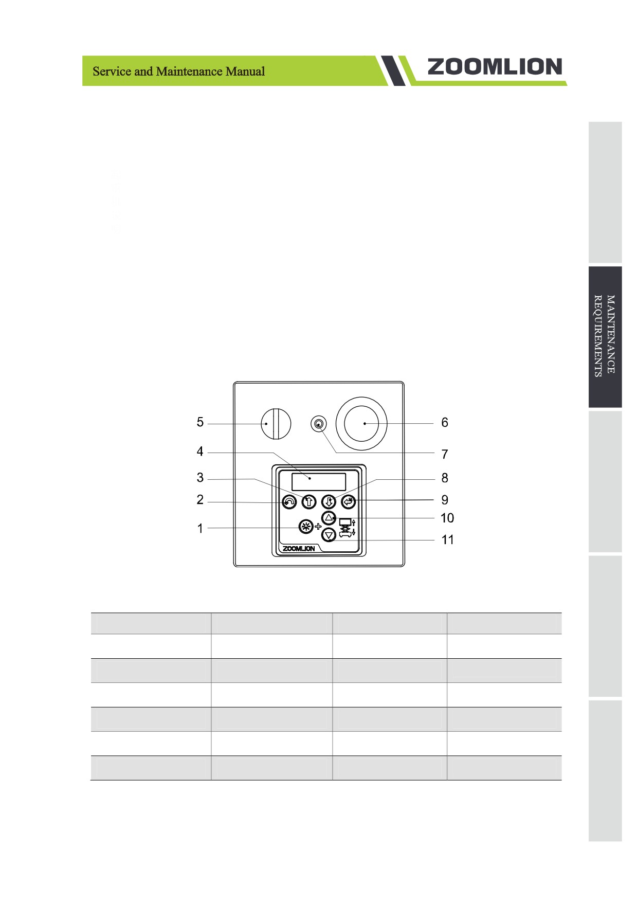
Figure 2-10 Ground control panel
Table 2-4 Ground control panel instruction
No.
Name
No.
Name
1
Lifting enable button
2
Menu escape button
3
Menu up button
4
LCD diagnostic
Emergency stop
5
Key switch
6
7
10A breaker
8
Menu down button
9
Menu enter button
10
Platform up button
11
Platform down button
a) Turn the key switch to Ground Control and pull out the red Emergency Stop button to the on position
at both the ground and platform controls,
b) Press the red Emergency Stop button to the off position at ground control.
2-15
Result: the machine has no movements.
c) Turn the key switch to Platform Control and pull out the red Emergency Stop button to the on position
at both the ground and platform controls,
d) Press the red Emergency Stop button to the off position at platform control.
Result: the machine has no movements.
The red Emergency Stop button can stop all operations of the machine.
2.6.3.6 Test key switch
This inspection is conducted every 250 hours or quarter, whichever comes first.
Proper key switch action and response are essential to the safe operation. The key switch can be switched
by the ground controller or platform controller. Invalid key switch could result in dangerous operation.
Operator must use the platform controller on the ground when performing this step.
a) Pull out the red Emergency Stop button to the on position at both the ground and platform controls.
b) Turn the key switch to platform control.
c) Inspect the raising and lowering functions at ground control.
1) Result: the machine has no movements.
d) Turn the key switch to ground control.
e) Inspect the raising and lowering functions at platform control.
1) Result: the machine has no movements.
f)
Turn the key switch to off position.
2) Result: the machine has no movements.
2.6.3.7 Test the horn
This inspection is conducted every 250 hours or quarter, whichever comes first.
Horn is used to alert operators and ground personnel of machine proximity and motion. A malfunctioning
horn cannot alert the ground personnel to a dangerous or unsafe condition.
a) Turn the key switch to Platform Control and pull out the red Emergency Stop button to the on position
at both the ground and platform controls,
1) Press the horn button at the platform control.
b) Result: the horn should sound.
2.6.3.8 Test the drive brakes
This inspection is conducted every 250 hours or quarter, whichever comes first.
2-16
Proper brake action is essential to safe machine operation. The drive brake should operate smoothly, free
of hesitation, jerking and unusual noise. There is no difference in the appearance of the tire before and
after the release of the brakes.
Select a test area that is firm, level and free of obstructions. Be sure the platform extension deck is fully
retracted and the platform is in the stowed position.
a) Mark a test line on the ground for reference.
b) Turn the key switch to Platform Control and pull out the red Emergency Stop button to the on position
at both the ground and platform controls.
c) Lower the platform to stowed position.
d) Press the drive function selection button.
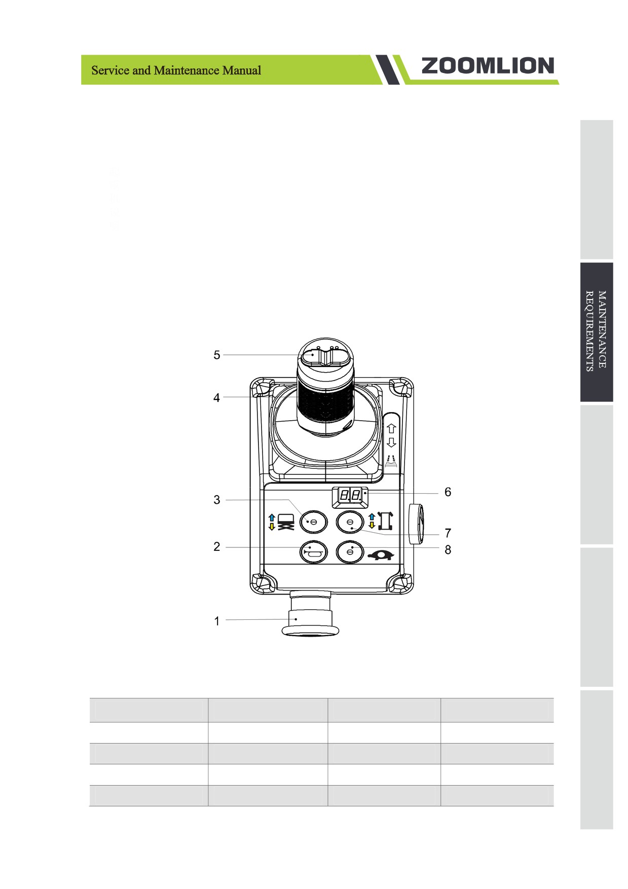
Figure 2-11 Platform control panel
Table 2-5 Platform control panel instruction
No.
Name
No.
Name
1
Emergency stop switch
2
Horn Button
3
Lift function button
4
Control handle
5
Steering thumb button
6
LED Readout
7
Drive function button
8
Drive speed button
2-17
a) Choose a point on the machine (i.e., contact patch of a tire) as a visual reference for use when
crossing the test line.
b) Bring the machine to top drive speed before reaching the test line. Release the drive joystick when
your reference point on the machine crosses the test line.
c) Measure the distance between the test line and your machine reference point. The maximum braking
distance on flat ground is 50cm ± 10cm/20in ± 4in, the maximum braking distance on slope braking
is 100cm ± 10cm/ 40in ± 4in.
1) Result: the machine will stop within the specified braking distance, passing the test.
2) Result: the machine will not stop within the specified braking distance.
3) The brakes must be able to hold the machine on any slope it is able to climb.
d) Replace the brake. Repeat the above process from the step a until the test qualified.
2.6.3.9 Test the top drive speed - stowed position
This inspection is conducted every 250 hours or quarter, whichever comes first.
Proper drive function is essential to safe operation. The drive function should respond quickly and
smoothly to operator control. Drive performance should also free of hesitation, jerking and unusual noise
over the entire speed range.
Select a test area that is firm, level and free of obstructions.
a) Create start and finish lines by marking two lines on the ground 10m/32ft10in apart.
b) Turn the key switch to Platform Control and pull out the red Emergency Stop button to the on position
at both the ground and platform controls.
c) Lower the platform to stowed position.
d) Press the drive function selection button.
e) Choose a point on the machine (i.e., contact patch of a tire) as a visual reference for use when
crossing the test line.
f)
Continue at full speed and begin to recording the time when your reference point crosses the start
line.
g) Record the time when the machine reference point crosses the finish line. The time is between 10.6
~ 12 s.
2.6.3.10 Test the drive speed - raised position
This inspection is conducted every 250 hours or quarter, whichever comes first.
Proper drive function is essential to safe operation. The drive function should respond quickly and
smoothly to operator control. Drive performance should also free of hesitation, jerking and unusual noise
2-18
over the entire speed range.
Select a test area that is firm, level and free of obstructions.
a) Create start and finish lines by marking two lines on the ground 10m/32ft 10in apart.
b) Turn the key switch to Platform Control and pull out the red Emergency Stop button to the on position
at both the ground and platform controls.
c) Press the lifting function selection button.
d) Press and hold the function enable button on the control handle, and push the handle to raise the
platform to a safe height (the bottom of the platform is about 2.4 m/7ft 10in above the ground).
e) Press the drive function selection button.
f)
Choose a point on the machine (i.e., contact patch of a tire) as a visual reference for use when
crossing the test line.
g) Continue at full speed and beginning timing when your reference point crosses the start line.
h) Continue at full speed and note the time when the machine reference point crosses the finish line.
The time is between 75-120s.
2.6.3.11 Test slow drive speed - stowed position
This inspection is conducted every 250 hours or quarter, whichever comes first.
Proper drive function is essential to safe operation. The drive function should respond quickly and
smoothly to operator control. Drive performance should also free of hesitation, jerking and unusual noise
over the entire speed range.
Select a test area that is firm, level and free of obstructions.
a) Create start and finish lines by marking two lines on the ground 10m/32ft 10in apart.
b) Turn the key switch to Platform Control and pull out the red Emergency Stop button to the on position
at both the ground and platform controls.
c) Lower the platform to stowed position.
d) Press the drive function selection button.
e) Choose a point on the machine (i.e., contact patch of a tire) as a visual reference for use when
crossing the test line.
f)
Continue at full speed and beginning timing when your reference point crosses the start line.
g) Continue at full speed and note the time when the machine reference point crosses the finish line,
the time is between 20s and 24s.
2-19
2.6.3.12 Hydraulic oil analysis
This inspection is conducted every 250 hours or quarter, whichever comes first.
Replace or test hydraulic oil is essential to good machine performance and service life. Dirty hydraulic
oil and suction filters can affect machine performance, and continuous use can damage components. This
operation should be performed more frequently under severe working conditions.
See 2.6.6.1 Test or Replace Hydraulic Oil.
2.6.3.13 Inspect hydraulic oil tank cap venting system
This inspection is conducted every 250 hours or quarter, whichever comes first.
Free-breathing tank is essential to good machine performance and service life. Unclean or clogged venting
caps can cause poor machine performance. Extremely dirty conditions may require more often inspection.
a) Remove the venting cap from the tank.
b) Venting inspection.
1) Result: air passes through the venting cap.
2) Result: if air does not pass the venting cap, clean or replace the venting cap. Proceed to step c.
3) When checking for positive venting, air should pass freely through the venting cap.
c) Carefully clean the tank vent cap with a mild solvent. Dry with low pressure compressed air. Repeat
step b.
d) Install the venting cap.
2.6.3.14 Inspect tray latch components
This inspection is conducted every 250 hours or quarter, whichever comes first.
Maintaining the module tray latch components in good condition is essential to good performance and
service life. Damaged latch components may result in module trays opening unexpectedly, creating an
unsafe operating condition.
a) Inspect each module tray latch and related components for wear.
b) Using light oil, apply a few drops to each of springs and to the sides of the latch mechanism.
2.6.3.15 Inspect down limit switch, level sensor and pothole limit switch
This inspection is conducted every 250 hours or quarter, whichever comes first.
Proper limit switch is essential to good performance and safe operation. A faulty limit switch could cause
result in reduced machine performance and a potential unsafe operating condition.
Select a test area that is firm, level and free of obstructions.
a) Down limit switch
2-20
1) Turn the key switch to ground control.
2) Raise the platform above safe working height greater than 2.4m/7ft 10in.
3) Lower the platform.
4) Result: platform will stop raising at the height of 2.4m/7ft 10in. Press the down button again to
lower the platform. Proper down limit switch.
5) Result: platform does not stop raising at the height of 2.4m/7ft 10in. Check if the down limit
switch and metal activates on the fixed shaft are loose. OR replace down limit switch.
Keep hands away from the safety arm when lowering the platform.
a)
Tilt switch
1) Move the machine onto a grade which exceeds the rating of the level sensor. Refer to the serial
label on the machine.
2) Press the lift function button, attempt to raise the platform to approximately 2.4m/7ft 10in.
3) Result: the ground controls LCD displays "LL", the alarm sounds. The machine is functioning
properly.
4) Result: diagnostic display does not shows "LL", the alarm does not sound. Adjust or replace the
level sensor.
b)
Pothole limit switch
1) Lower the platform to stowed position. Move the machine to a level ground.
2) Place a wooden block approximately 5cm/2in tall under the right pothole guard.
3) Attempt to raise the platform to approximately 2.4m/7ft 10in.
4) Result: the pothole guard contacts the block and does not fully deploy. The diagnostic display
shows code 18, alarm sounds.Machine functions normally:
5) Result: the pothole guard contacts the block and does not fully deploy. The diagnostic display
does not show code 18, alarm does not sound.The machine can continue to rise. Adjust or
replace the pothole limit switch.
2.6.3.16 Inspect up limit switch
This inspection is conducted every 250 hours or quarter, whichever comes first.
Proper limit switch is essential to good performance and safe operation. A faulty limit switch could cause
result in reduced machine performance and a potential unsafe operating condition.
Select a test area that is firm, level and free of obstructions.
2-21
a) Turn the key switch to Ground Control, and attempt to raise the platform to approximately 2.4m/7ft
10in.
b) Lift the safety arm, move the safety arm to the middle of the scissor bushing and rotate it down to
the vertical position.
c) Lower the platform until the safety arm is in full contact with the bushing.
Keep hands away from the safety arm when lowering the platform.
a) Open the limit switch cover on the chassis.
b) Slightly raise the platform, restore the safety arm.
c) Use the ground controller to lift the platform while pressing the up limit switch arm to activate the
up limit switch.
1) Result: platform stops raising. The machine is functioning properly.
2) Result: platform continues to raise. Adjust or replace up limit switch.
2.6.4 Maintenance every 6 months
2.6.4.1 Inspect platform overload system
This inspection is conducted every 500 hours or 6 months, whichever comes first. Check immediately
when the machine has an overload fault.
Testing the platform overload system regularly is essential to safe machine operation. Continued use of
an improperly operating platform overload system result in the system not sensing an overload platform
condition. Machine stability could be compromised resulting in the machine tipping over.
The platform overload system is designed to prevent machine operation in the event the platform is
overloaded. Platform overload system is composed of two electrical components: overload pressure
transducer and the angel sensor.
The overload pressure transducer is used to determine the pressure for feedback to the platform overload
system. When the pressure is too high, the pressure sensor will send a signal to ECU and all functions of
the machine will stop until the excess load is removed from the platform.
Angle sensor, located at the fork 1 of scissor arm, is used to measure the tilt angle of the scissor to
determine the height of the platform.
a) Move the machine to a firm and level ground.
b) Place heavy objects on the platform (286kg/630lbs for ZS4555, 385kg/850lbs for ZS4045 / ZS3246,
253kg/560lbs for ZS2632, 418kg/920lbs for ZS2032, 253kg/560lbs for ZS1930, and 264kg/580lbs
for ZS1530).
2-22
c) Turn the key switch to Ground Control, and attempt to raise the platform to approximately 2.4m/7ft
10in.
1) Result: alarm will sound, display shows OL.
2) Result: alarm does not sound, and display does not show OL. Platform continues to raising
3) Perform load calibration again or contact professional service personnel.
2.6.4.2 Replace the hydraulic tank venting cap
This inspection is conducted every 500 hours or 6 months, whichever comes first. Check immediately
when the machine has an overload fault.
The hydraulic tank is a vented tank. There is an air filter inside the venting cap that may become clogged
over time. If the vent cover fails or is improperly installed, once the impurities enter the hydraulic system,
it may cause damage to the components. Extremely dirty conditions may require more often inspection.
a) Remove the venting cap.
b) Replace a new hydraulic tank venting cap.
2.6.4.3 Replace hydraulic filters
This inspection is conducted every 1,000 hours or year, whichever comes first.
Proper filter condition is essential to good machine performance and service life. Dirty or clogged filters
will affect machine performance and damage components. Under hostile environment and bad operating
conditions, the filter should be checked and replaced more frequently.
Contact with hot oil can cause serious burns.
a) Clean the hydraulic fluid that is spilled around the filter. Use a wrench to remove the filter.
b) Apply a layer of hydraulic oil to the seal of the new filter.
c) Install a new filter and tighten it by hand.
d) Use the marker to mark the replacement time and date on the filter replacement form.
e) Turn the key switch to Ground Control and pull out the red Emergency Stop button to the on position
at both the ground and platform controls,
f)
Press and hold down the lift function selection button.
g) Check the leak of filter.
h) Clean the hydraulic fluid that is spilled around the filter.
2.6.5 Maintenance every year
The scissor wear-resistant slider inspection is performed every 1000 hours or every 12 months, whichever
2-23
comes first.
Maintaining the condition of the scissor wear pads is essential to safe machine operation. Continued use
of worn out wear pads may result in component damage and unsafe operating conditions.
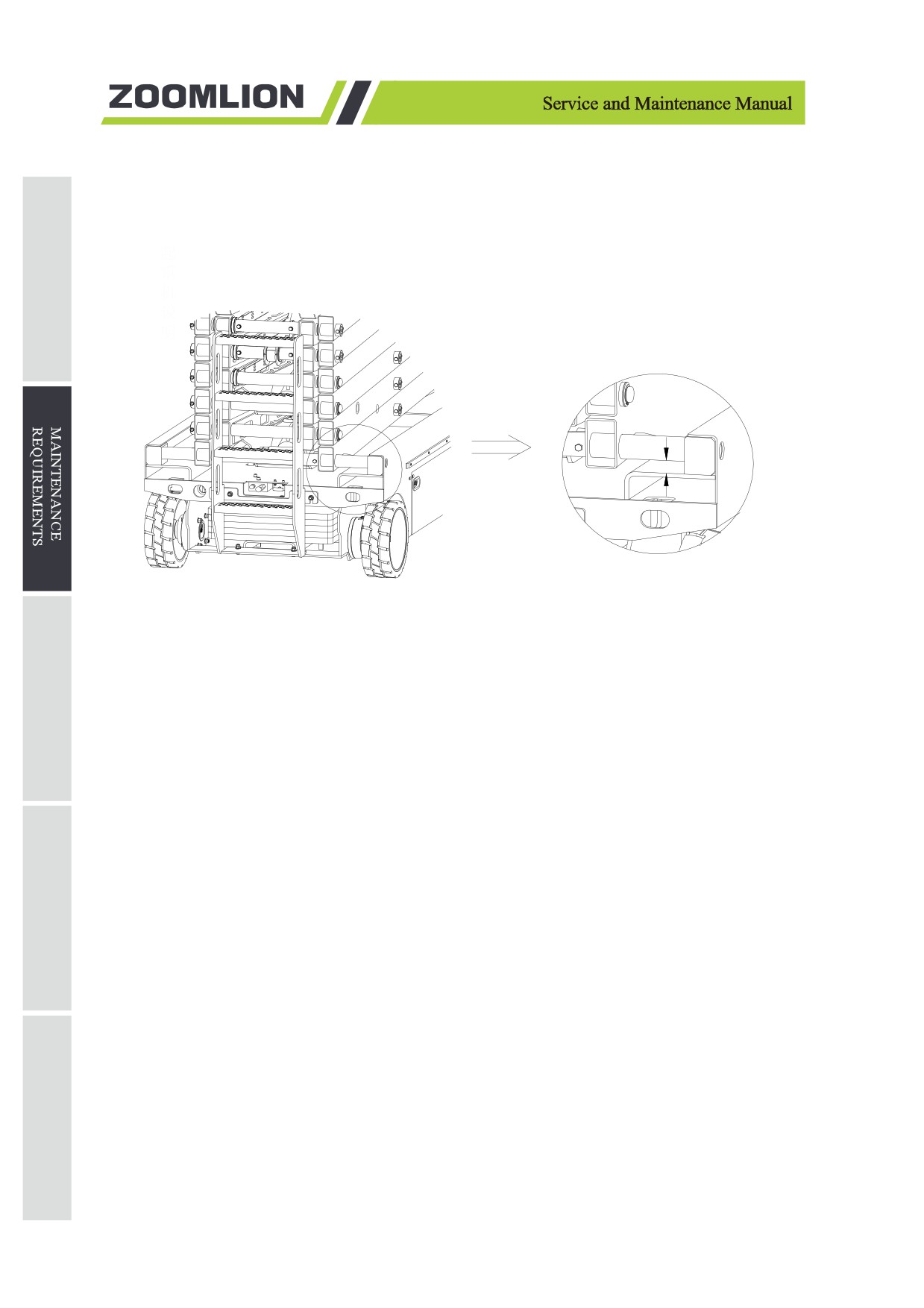
Check the wear-resistant slider with the platform stowed.
space between here
Figure 2-12 Inspection of wear pad
a)
Measure the distance between the number one inner arm across tube and the chassis deck at the
ground control side of the non-steer end of the machine.
1) For ZS4555HD/ZS4555DC/ZS4555HD-Li/ZS4555DC-Li machines.
Result: the measurement is 49 mm/2in or more. Proceed to step b.
Result: the measurement is less than 49mm/2in. Replace wear pads.
2) For ZS4045HD/ZS4045DC/ZS3246HD/ZS3246DC/ZS2632HD/ZS2632DC/ZS2032HD/
ZS2032DC/ZS4045HD-Li/ZS4045DC-Li/ZS3246HD-Li/ZS3246DC-Li/ZS2632HD-Li/
ZS2632DC-Li/ZS2032HD-Li/ ZS2032DC-Li machines.
Result: the measurement is 24mm/1in or more. Proceed to step b.
Result: the measurement is less than 24mm/1in. Replace wear pads.
3) For ZS1930HD/ZS1930DC/ZS1930HD-Li/ZS1930DC-Li machines.
Result: the measurement is 39 mm/2 in or more. Proceed to step b.
Result: the measurement is less than 39mm/2 in. Replace wear pads.
4) For ZS1530DC/ZS1530DC-Li machines.
Result: the measurement is 36 mm/1 in or more. Proceed to step b.
Result: the measurement is less than 36mm/1 in. Replace wear pads.
2-24
///////////////////////////////////////