Doosan Solar 255LC-V. Operation and Maintenance Manual (2002) - page 3
4.
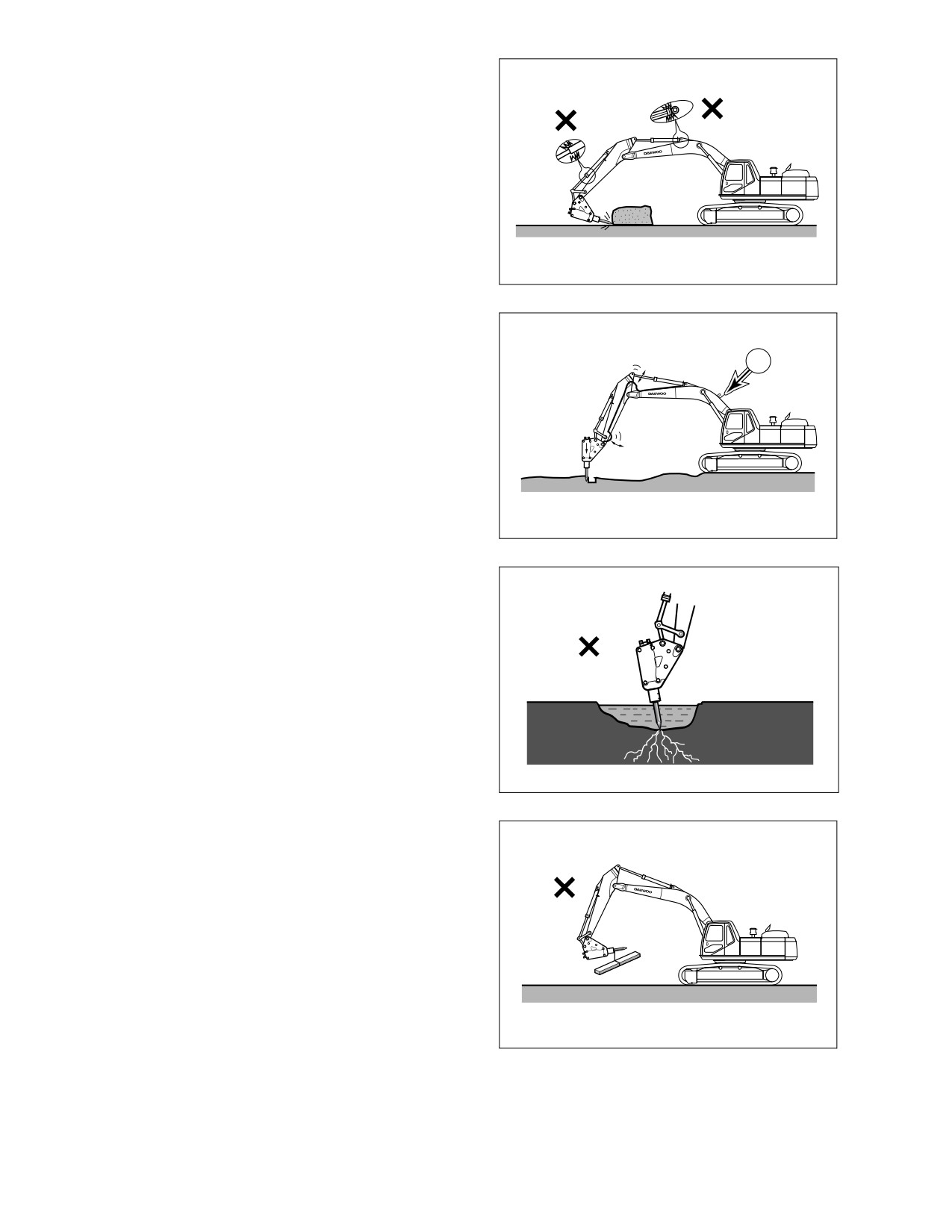
DO NOT operate the breaker with the
boom or arm cylinders fully extended
(bottomed out). See Figure 72.
Leave over 100 mm (4 in) of clearance
between rod end of cylinder and cylinder
head. This will help prevent damage to
cylinders during breaker operation.
HAOB940L
Figure 72
5.
DO NOT use the breaker if the hydraulic
hoses vibrate excessively. See Figure 73.
Check the breaker’s hydraulic accumulator
1
(1) for damage and repair as required. If
excavator is operated under this condition,
structural and hydraulic components can
be damaged.
HAOB950L
Figure 73
6.
DO NOT allow the breaker body to go into
water if not equipped for underwater
operation. The breaker seal can be
damaged and allow rust, foreign material
or water to enter the hydraulic system and
cause damage. Only insert the breaker
tool into water. See Figure 74.
HAOB970L
Figure 74
7.
DO NOT any lifting or towing with a
breaker. See Figure 75.
HAOB980L
Figure 75
022-00031E Operation and Maintenance Manual
Operation 3-33
8.
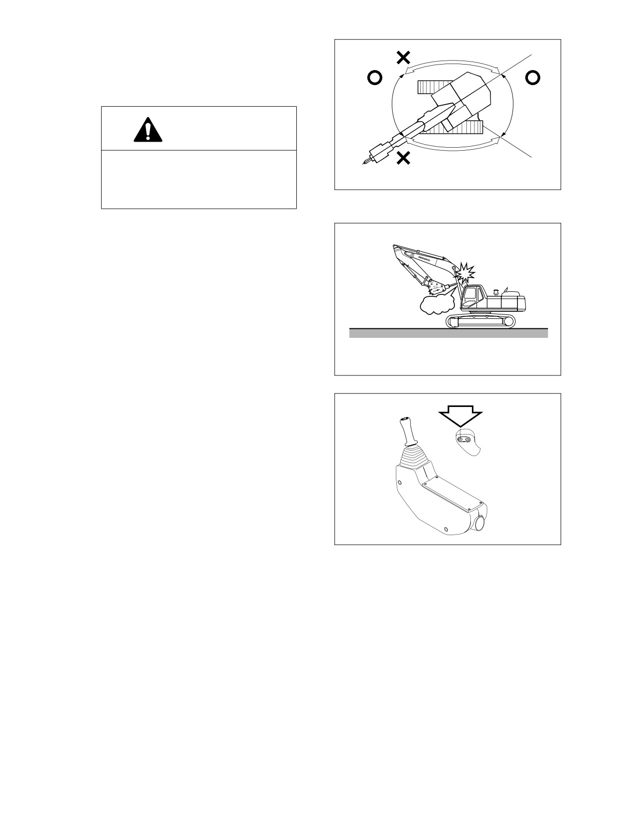
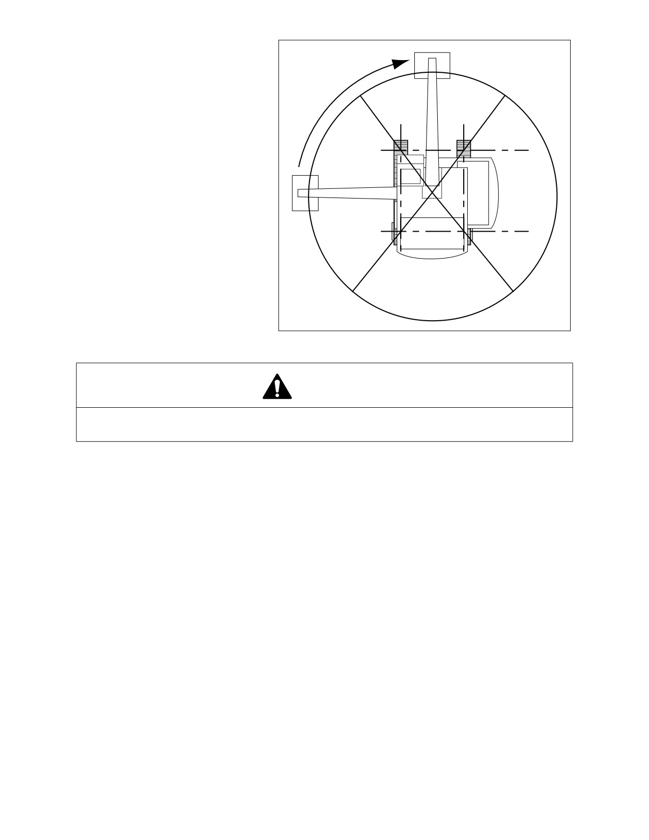
Operate the breaker only to the front and
rear of the excavator. DO NOT use the
breaker to either side of the excavator. DO
NOT swing the breaker from side to side
when operating it. See Figure 76
WARNING!
Operating a breaker with the upper
body turned 90° to the tracks can
result in tipping over the machine or
HAOB990L
reduction in service life.
Figure 76
9.
DO NOT curl the breaker tool tip into the
arm or boom when traveling or parking the
excavator. See Figure 77.
HAOB960L
Figure 77
TO ACTIVATE BREAKER;
1.
Press the left side button on the top of the
right hand work lever (joystick) to activate
the hydraulic breaker.
2.
Release the left side button on the top of
the right hand work lever
(joystick) to
deactivate the hydraulic breaker.
ARO0120L
Figure 78
3-34 Operation
022-00031E Operation and Maintenance Manual
HYDRAULIC OIL AND FILTER SERVICE INTERVALS
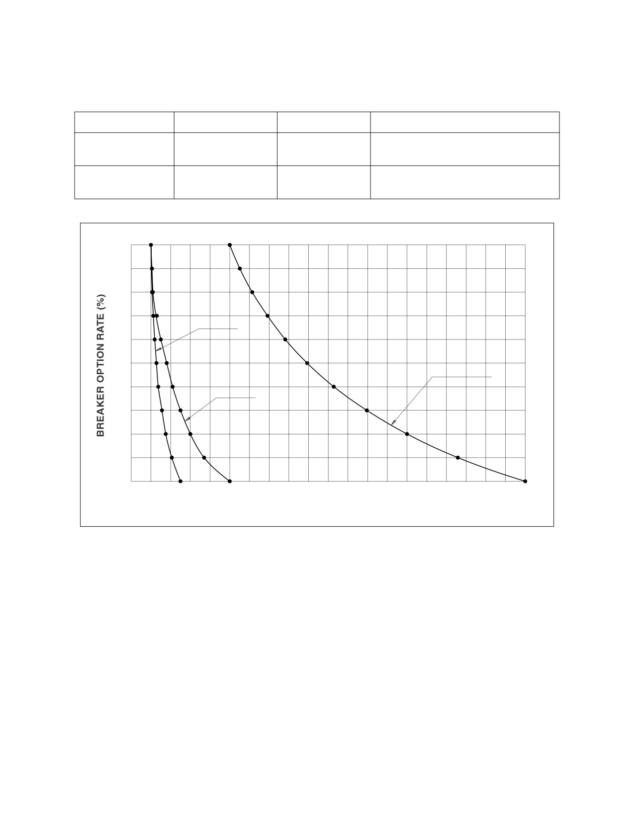
When using a hydraulic breaker, the viscosity breakdown and contamination of hydraulic oil is faster
because the work condition is more severe than during normal digging work. To prevent the hydraulic
components (especially pump) from having a shortened life-cycle, replace the hydraulic oil and main
hydraulic oil filter using the following schedule.
ATTACHMENT
OPERATION RATE
HYDRAULIC OIL
FILTER
250 HOURS (First Replacement)
BUCKET WORK
100%
2000 HOURS
500 HOURS (After First Replacement)
HYDRAULIC
100%
500 HOURS
100 HOURS
BREAKER WORK
100
105
551
106
110
614
80
112
130
692
FILTER
119
150
(First Replacement)
782
60
128
180
893
HYDRAULIC OIL
137
210
1028
40
FILTER
250
(After First Replacement)
1196
156
175
300
1400
20
206
370
1658
0
0
500
1000
1500
2000
MACHINE OPERATING HOURS
ARO0990L
Figure 79
NOTE: The replacement intervals of hydraulic oil and filter depend upon the amount of time the
hydraulic breaker is being used. These intervals should be followed as opposed to
regularly scheduled maintenance.
022-00031E Operation and Maintenance Manual
Operation 3-35
OPERATING TECHNIQUES
LIFTING
IMPORTANT
There may be local or government regulations, about the use of excavators for the lifting of
heavy loads. Always contact your local and government agencies in regards to these
regulations.
To prevent injury, do not exceed the rated load capacity of the machine. If the machine is not on level
ground, load capacities will vary.
Short slings will prevent excessive load swing.
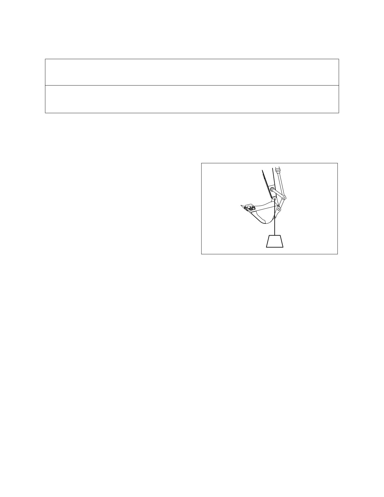
Use the lifting eye on the bucket that is provided to lift objects.
Always try to maintain the lifting eye (Figure 80)
straight below the centerline of the arm and
bucket pin. In this manner the weight of the load
is being primarily held only by the pin, and not
by the bucket cylinder, link, and link pins.
When a lifting eye is used, the sling/lifting device
must be fastened to the eye in a manner that will
not allow it to come loose.
The most stable position is over the corner of
the machine.
For best stability, carry a load as close to the
HAAD3830
ground and machine as possible.
Figure 80
Lift capacity decreases as the distance from the
machine swing centerline is increased.
3-36 Operation
022-00031E Operation and Maintenance Manual
Lifting Unknown Weight
When loads are not accurately
known are to be lifted, the person
responsible for the job shall
ascertain that the weight of the
FRONT LIFT
load does not exceed the machine
ZONE
LOAD RATING CHART at the
radius at which it is to be lifted.
It is recommended that you feel
your way into any lift as a
precaution against tip-over. One
SIDE LIFT
SIDE LIFT
method is to position the boom at
ZONE
ZONE
90° over the side of the machine.
Slowly lift the load until it clears the
ground. A lift over the side is the
most unstable, and as the load is
swung into the front zone of the
excavator it will become more
stable. DO NOT INCREASE
REAR LIFT
SWING RADIUS AFTER THE
ZONE
LOAD IS LIFTED.
HAAD3842
Figure 81
DANGER!
If a load is picked up from the front zone and swung into the side zone, a tip-over could result
causing a deadly or fatal injury.
Lifting Known Weight
The load chart is the governing factor when lifting known weights. It is recommended that you feel your way
into any lift as a precaution against tip-over. When ever possible, lift and swing payloads between the front
idler area.
Pick and Carry
The machine has the ability to pick and carry payloads without added labor. We recommend when traveling
with a suspended payload, you evaluate the prevailing conditions and determine the safety precautions
required in each case. The following factors must be considered before attempting to pick and carry a load.
Align the boom with the forward direction of machine travel. Maintain this boom position when turning the
machine. Turn only when necessary, at the slowest speed, and at a wide turning radius.
1.
Use the shortest lifting radius distance possible.
2.
Keep the load as close to the ground as conditions will permit.
3.
Provide tag lines to prevent load from pendulating. Pendulating can cause a change in radius. A
change in radius could exceed the load chart rating or cause a tip-over condition.
4.
Govern travel speed to suit conditions.
5.
Avoid sudden starts and stops.
022-00031E Operation and Maintenance Manual
Operation 3-37
OPERATION UNDER UNUSUAL CONDITIONS
NOTE: See “Maintenance in Special Conditions” on page 4-67 for other recommendations.
OPERATION IN EXTREME COLD
If machine is to be operated in extreme cold weather temperatures, certain precautions must be taken to
assure continued normal operation. The following paragraphs detail checks to be made to be certain the
machine is capable of operating at these temperatures.
1.
Check the cooling system for correct antifreeze solution for lowest temperature expected. Carefully
inspect cooling system and correct or report any leaks.
2.
Keep batteries fully charged to prevent freezing. If water is added to batteries, run engine at least one
hour to mix electrolyte solution.
3.
Keep engine in best possible mechanical condition to assure easy starting and good performance
during adverse weather conditions.
4.
Use engine oil of the proper specifications for the expected temperatures. Refer to the "Lubrication
Specifications" of the engine manual for details.
5.
Keep fuel tank full at all times. Drain condensation from tank before and after operation. Drain and
service fuel filter. To eliminate clogging of fuel filters due to wax crystal formation in the fuel, be sure
that the fuel used has a cloud point specification below the lowest expected temperature.
6.
Lubricate entire machine according to "Periodic Service Table and Chart" Section 4, in this manual or
lubrication chart on machine.
7.
Start engine and allow it to reach normal operating temperature before applying load.
A. If mud and ice collects and freezes on any of the moving parts while machine is idle, apply heat
to thaw the frozen material before attempting to operate machine.
B. Operate hydraulic units with care until they have reached a temperature to enable them to
operate normally.
C. Check all machine controls and/or functions to be sure they are operating correctly.
8.
An extra outer air filter element should be kept in the operator's cab to replace element that could
become iced and cause restricted air flow to engine.
9.
If cold weather starting aid must be used, see "Engine Starting" COLD WEATHER START portion of
this manual.
10.
Clean off all mud, snow and ice to prevent freezing. Cover machine with tarpaulin if possible, keep
ends of tarpaulin from freezing to ground.
OPERATION IN EXTREME HEAT
Continuous operation of the machine in high temperatures may cause the machine to overheat. Monitor
engine and transmission temperatures and stop machine for a cooling-off period whenever necessary.
1.
Make frequent inspections and services of the fan and radiator. Check coolant level in radiator. Check
grills and radiator fins for accumulation of dust, sand and insects which could block the cooling
passages.
A. Formation of scale and rust in cooling system occurs more rapidly in extremely high
temperatures. Change antifreeze each year to keep corrosion inhibitor at full strength.
B. If necessary, flush cooling system periodically to keep passage clear. Avoid use of water with a
high alkali content which increases scale and rust formation.
3-38 Operation
022-00031E Operation and Maintenance Manual
2.
Check level of battery electrolyte daily. Keep electrolyte above plates preventing damage to batteries.
Use a slightly weaker electrolyte solution in hot climates. Dilute 1.280 specific gravity electrolyte as
issued to 1.200 to 1.240 specific gravity readings at full charge. Recharge batteries whenever they
reach a 1.160 specific gravity reading. Batteries self-discharge at a higher rate if left standing for long
periods at high temperatures. If machine is to stand for several days, remove batteries and store in a
cool place.
WARNING!
Do not store acid-type storage batteries near stacks of tires; the acid fumes have a harmful
affect on rubber.
3.
Service fuel system as directed in "Engine Fuel System" Section 5, of this manual. Check for water
content before filling fuel tank. High temperatures and cooling off cause condensation in storage
drums.
4.
Lubricate as specified in "Periodic Service Chart and Table" Section 4, in this manual or Lubrication
Decal on the machine.
5.
Do not park machine in sun for long periods of time. When practical park machine under cover to
protect it from sun, dirt and dust.
A. Cover inactive machine with tarpaulin if no suitable shelter is available. Protect engine
compartment, transmission and hydraulics from entrance of dust.
B. In hot, damp, climates corrosive action will occur on all parts of the machine and will be
accelerated during the rainy season. Rust and paint blisters will appear on metal surfaces and
fungus growth on other surfaces.
C. Protect all unfinished, exposed surfaces with a film of preservative lubricating oil. Protect cables
and terminals with ignition insulation compound. Apply paint or suitable rust preventive to
damaged surfaces to protect them from rust and corrosion.
OPERATION IN DUSTY OR SANDY AREAS
Operation of the machine can cause dust in almost any area. However, when in predominantly dusty or
sandy areas, additional precautions must be taken.
1.
Keep cooling system fins and cooling areas clean. Blow out with compressed air, if possible, as often
as necessary.
WARNING!
Wear goggles when using compressed air.
2.
Use care when servicing fuel system to prevent dust and sand from entering the tank.
3.
Service the air cleaner at frequent intervals, check air restriction indicator daily and keep dust cup
and dust valve clean. Prevent dust and sand from entering engine parts and compartments as much
as possible.
4.
Lubricate and perform services outlined on current lubrication chart on machine and "Lubrication
Chart and Table" Section 4. Clean all lubrication fittings before applying lubricant. Sand mixed with
lubricant becomes very abrasive and speeds wear on parts.
022-00031E Operation and Maintenance Manual
Operation 3-39
5.
Protect machine from dust and sand as much as possible. Park machine under cover or protect with
tarpaulin to keep dust and sand from damaging unit.
OPERATION IN RAINY OR HUMID CONDITIONS
Operation under rainy conditions is similar to that as in extreme heat procedures listed previously.
1.
Keep all exposed surfaces coated with preservative lubricating oil. Pay particular attention to
damaged or unpainted surfaces. Cover all paint cracks and chip marks as soon as possible to prevent
corrosive effects.
OPERATION IN SALT WATER AREAS
The corrosive effect of salt water and salt water spray is very extensive. When operating in salt water
areas, observe the following precautions.
1.
When exposed to salt water, dry machine thoroughly and rinse with fresh water as soon as possible.
2.
Keep all exposed surfaces coated with preservative lubricating oil. Pay particular attention to
damaged paint surfaces.
3.
Keep all painted surfaces in good repair.
4.
Lubricate machine as prescribed on lubrication chart on machine or "Periodic Service Table and
Chart" Section 4, in this manual. Shorten lubricating intervals for parts subject to exposure to salt
water, if found to be necessary.
OPERATION AT HIGH ALTITUDES
Normally, operation of machine at high altitudes will be as outlined in extreme cold. Before operating at
high altitudes, engine fuel and air mixture may have to be adjusted according to appropriate engine
manual.
1.
Check engine operating temperature for evidence of overheating. The pressure cap on radiator must
make a perfect seal to maintain coolant pressure in the system.
3-40 Operation
022-00031E Operation and Maintenance Manual
4INSPECTION, MAINTENANCE AND
ADJUSTMENT
Routine maintenance and inspections are
required to keep your machine in the correct
operating condition. The following pages list the
inspection intervals, the system or component
checks and location references.
NOTE: The following pages list the
service checks and their
required intervals. The service
cycles may need to be
shortened depending on the
working conditions. Extremely
hot or dusty conditions will
HAOA600L
require more frequent service.
Figure 1
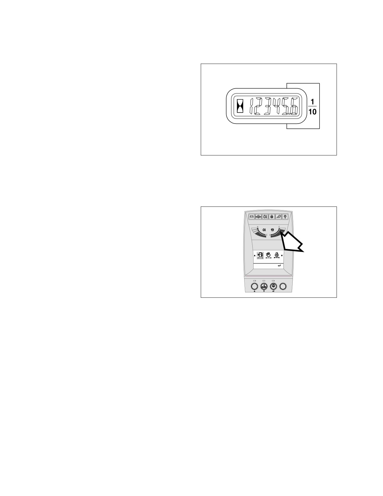
Operational
hours
are
determined by the amount of
time accumulated on the
engine hour meter on the
control console in the cab.
NOTE: Besides the normal hour meter,
the multifunction gauge can be
used to keep track of the hours
on individual filters. See “Filter /
Oil Info” on page 2-28.
1.Fuel Filter
Hrs: 0232 Reset:
POWER
AUTO
DISPLAY
ESC
HAAD3781
Figure 2
022-00031E Operation and Maintenance Manual
Inspection, Maintenance and Adjustment 4-1
SERIAL NUMBERS
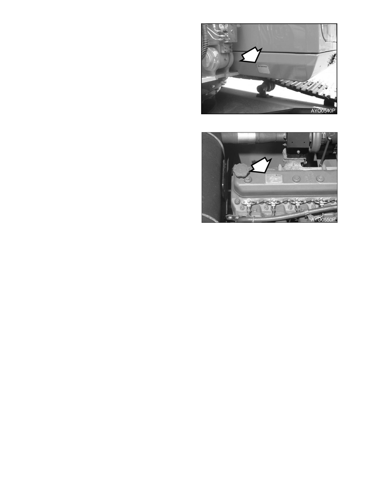
There are two serial number plates attached to
the body of the excavator. The machine serial
number plate (Figure 3) is on the right side of
the cab on the outside. The engine serial
number is stamped on the rear left side of the
engine block, above the starter. Additional
engine information is described on a label
(Figure 4) on the rocker cover.
Please make note of these numbers and their
locations. These will be required whenever
warranty service work is requested.
Figure 3
SAFETY PRECAUTIONS
1.
Make sure to lock out the hydraulic
controls and post a notice (Warning Tag)
that the machine is being serviced to
prevent any unauthorized operation.
2.
Make sure to clean up any fluid spills,
especially around the engine.
3.
Inspect all fuel lines to make sure that
fittings, lines, filters and O-rings, etc., are
tight and are not showing signs of wear or
damage.
Figure 4
4.
If the inspection or test procedure requires
that the engine be running, make sure to
keep all unauthorized personnel away from
the machine, and that all industry standard
safety precautions are followed.
4-2 Inspection, Maintenance and Adjustment
022-00031E Operation and Maintenance Manual
PRELIMINARY WORK MACHINE SETUP FOR
MAINTENANCE
When performing maintenance specified in this manual, always park the excavator as follows.
NOTE: Certain types of maintenance may require the machine to be positioned differently. Always
return machine to this position.
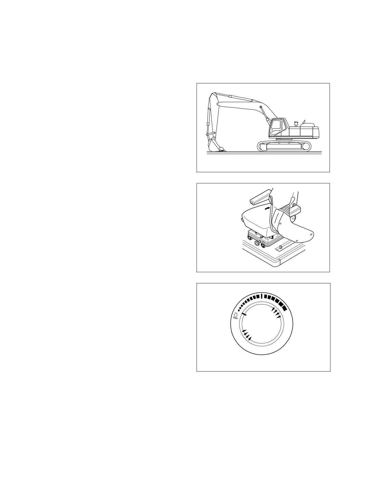
1.
Park on firm, level ground.
2.
Lower bucket to ground.
HAOB920L
Figure 5
3.
Set safety lever on "LOCK" position.
HAOA390L
Figure 6
4.
Allow engine to run at low idle for a
minimum of 5 minutes to allow engine to
cool. If this is not done, heat surge may
occur.
HAOB290L
Figure 7
022-00031E Operation and Maintenance Manual
Inspection, Maintenance and Adjustment 4-3
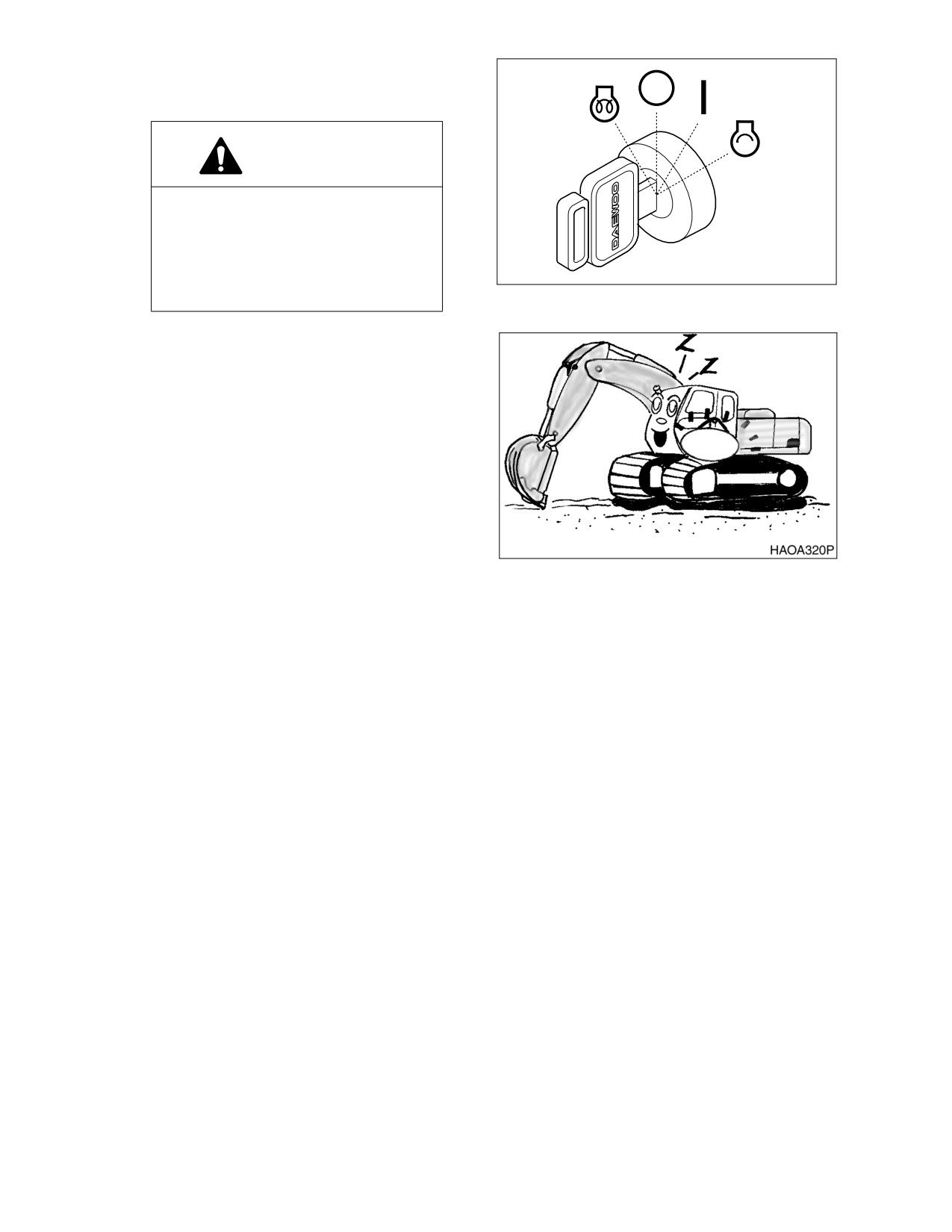
5.
Shut down engine by turning key to "O"
(OFF) position. Remove key from starter
switch.
WARNING!
If
engine must be run while
performing
maintenance,
use
extreme care. Always have
one
person in the cab at all times. Never
leave the cab with the engine
HAOA340L
running.
Figure 8
6.
Before starting maintenance work, hang
up a tag, "Do Not Touch When Performing
Inspection or Maintenance" on cab door or
work lever.
Figure 9
4-4 Inspection, Maintenance and Adjustment
022-00031E Operation and Maintenance Manual
TABLE OF RECOMMENDED LUBRICANTS
IMPORTANT
Do not use lubricants other than those recommended, without prior written approval from
Daewoo.
NOTE: Refer to the Maintenance Intervals Table for application points.
LUBRICANT
LUBRICANT
HYDRAULIC OIL*
ENGINE OIL**
GEAR OIL
MANUFACTURER
GREASE
CALTEX
CALTEX HD32
CALTEX RPM or
MULTIFAC EP
MULTIPURPOSE
EP90
DELO 300
EXXON/ESSO
NUTO (ANTI-
EXXON 15W40
RONEX MP #2 or
SPARTAN EP220
WEAR)
or
RONEX MP #1
HD 32 (BELOW
(COLD TEMPS)
EXXON GX
0°C (32°F)) or
80W90
HD 46 (ABOVE
0°C (32°F)) or
TERESSTIC
(ANTI-RUST)
MOBIL
MOBIL
DELVAC 1300 or
MOBIL FAW #2
MOBILUBE HD
or
80W90
DTE 13M (ALL-
SUPER 15W40
TEMP) or
MOBIL FAW #1
(COLD TEMPS)
DTE 24
(SUMMER)
SHELL
TELLUS 32
ROTELLA
ALVANIA EP #2
SPIRAX HD
80W90 or
T15W40
DONAX TD
(TRANSMISSION)
PENNZOIL
PENNZBELL
LONGLIFE
PENNZOIL 705
PENZOIL
EP #2
MULTIPUPOSE
AW 32 (BELOW
SAE15W40
4092 or
0°C (32°F)) or
80W90
AW 46 (ABOVE
0°C (32°F))
Hydraulic oil change interval is 2,000 hours, only when Daewoo Genuine Oil is used. If other
brands of oil is used, guaranteed change interval is 1,000 hours.
**
Engine oil must meet ACEA-E2, ACEA-E3 or API-CH-4 EQUIVALENT and be SAE 15W40 or
10W40.
022-00031E Operation and Maintenance Manual
Inspection, Maintenance and Adjustment 4-5
LUBRICANT
LUBRICANT
HYDRAULIC OIL*
ENGINE OIL**
GEAR OIL
MANUFACTURER
GREASE
DRYDEN
PARADENE
DIESELALL
EP #2 (RED)
AP80W90
PLUS 15W40
AW 32 (BELOW
0°C (32°F)) or
AW 46 (ABOVE
0°C (32°F))
CHEVRON
AW MV 32
DELO 400
DELO GREASE
DELOGEAR OIL
(BELOW 0°C
15W40
EP-2
or
(32°F)) or
RPM UNIV GEAR
AW MV 46
80W90
(ABOVE 0°C
(32°F))
TEXACO
RANDO
URSA SUPER
STAR PLEX 2
MULTIGEAR
PLUS 15W40 or
EPSAE 80W90
HD32 (BELOW
STAR PLEX
0°C (32°F)) or
URSA PREMIUM
PREMIUM
TDX 15W40
HD46 (ABOVE
0°C (32°F))
IDEMITSU
DAPHNE KOSAN
APOROIL
DAPHNE
APOROIL GEAR
KOSAN
46WR
MOTIRE S300
CORRONE #2
HE 90
NIPPON SEIKIYU
SUPER
LIPANOC
NISEKI SP90 or
HIGHLAND S26
GREASE
EP90
or 32
TOTAL
TOTAL EQUIVIS
TOTAL
TOTAL MUTRIS
TOTAL DA80W90
ZS46-III
EP #2
Hydraulic oil change interval is 2,000 hours, only when Daewoo Genuine Oil is used. If other
brands of oil is used, guaranteed change interval is 1,000 hours.
**
Engine oil must meet ACEA-E2, ACEA-E3 or API-CH-4 EQUIVALENT and be SAE 15W40 or
10W40.
IMPORTANT
Do not mix oils from different manufacturers. Daewoo does not endorse specific brands but
does suggest that owners select quality oils whose suppliers provide assurance that required
standards will always be met or exceeded.
Fluctuating daily or weekly extremes of temperature, or operation in sub-zero freezing weather
may make it impractical to use straight weight lubricants. Use good judgement in selecting
lubricant types that are appropriate for climate conditions.
4-6 Inspection, Maintenance and Adjustment
022-00031E Operation and Maintenance Manual
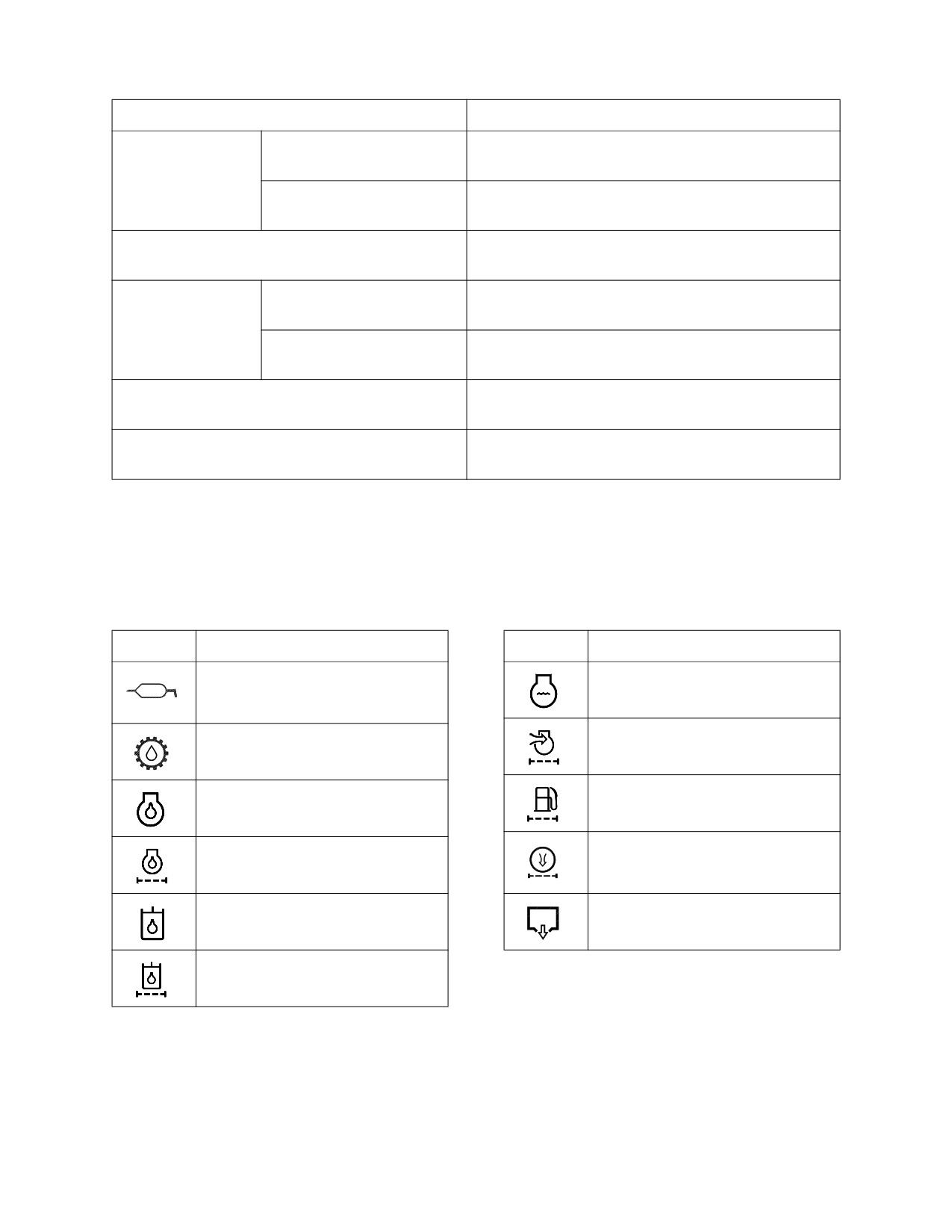
FLUID CAPACITIES
Component
Capacity
Engine
Oil Pan with Filter
21 liters
(5.5 U.S. gal.)
Cooling System
36 liters
(9.5 U.S. gal.)
Fuel Tank
370 liters
(98 U.S. gal.)
Hydraulic Oil
Tank Level
155 liters
(41 U.S. gal.)
System
290 liters
(77 U.S. gal.)
Traveling Device (Each)
5 liters
(1.3 U.S. gal.)
Swing Device
11 liters
(2.9 U.S. gal.)
LUBRICATION AND SERVICE CHART
Lubrication and service chart is on the inside of battery box cover. The symbols shown here are used in the
lubrication and service chart on the next page.
Symbol
Description
Symbol
Description
Lubrication
Coolant
Gear Oil
(Swing Device, Travel
Air Cleaner Element
Device)
Fuel Filter
Engine Oil
Engine Oil Filter
Air-conditioner Filter
Hydraulic Oil
Drain Water
Hydraulic Oil Filter
022-00031E Operation and Maintenance Manual
Inspection, Maintenance and Adjustment 4-7
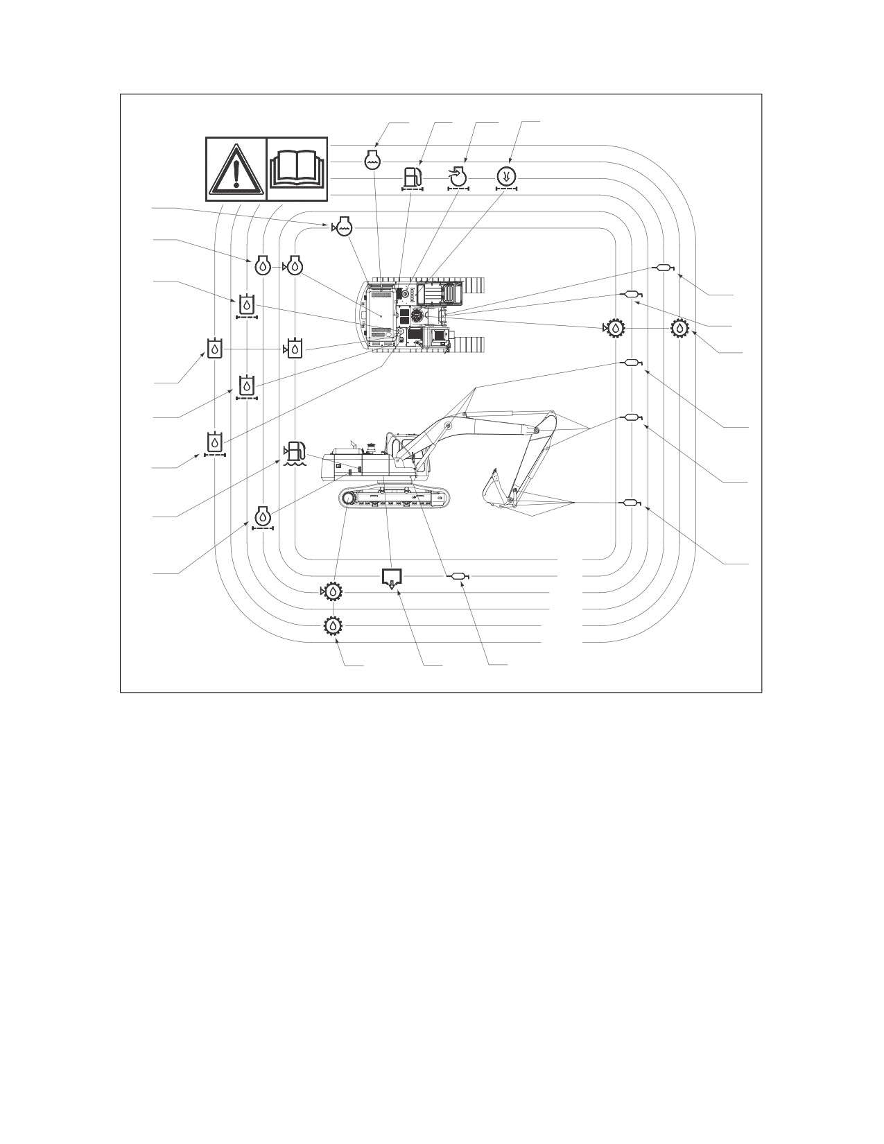
Description of Lubrication and Service Chart
9
15
16
17
18
6
11
3
2
4
7
12
1
13
1
10
10h
1
14
50h
250h
500h
1000h
2000h
5
8
1
AYO0070L
Figure 10
4-8 Inspection, Maintenance and Adjustment
022-00031E Operation and Maintenance Manual
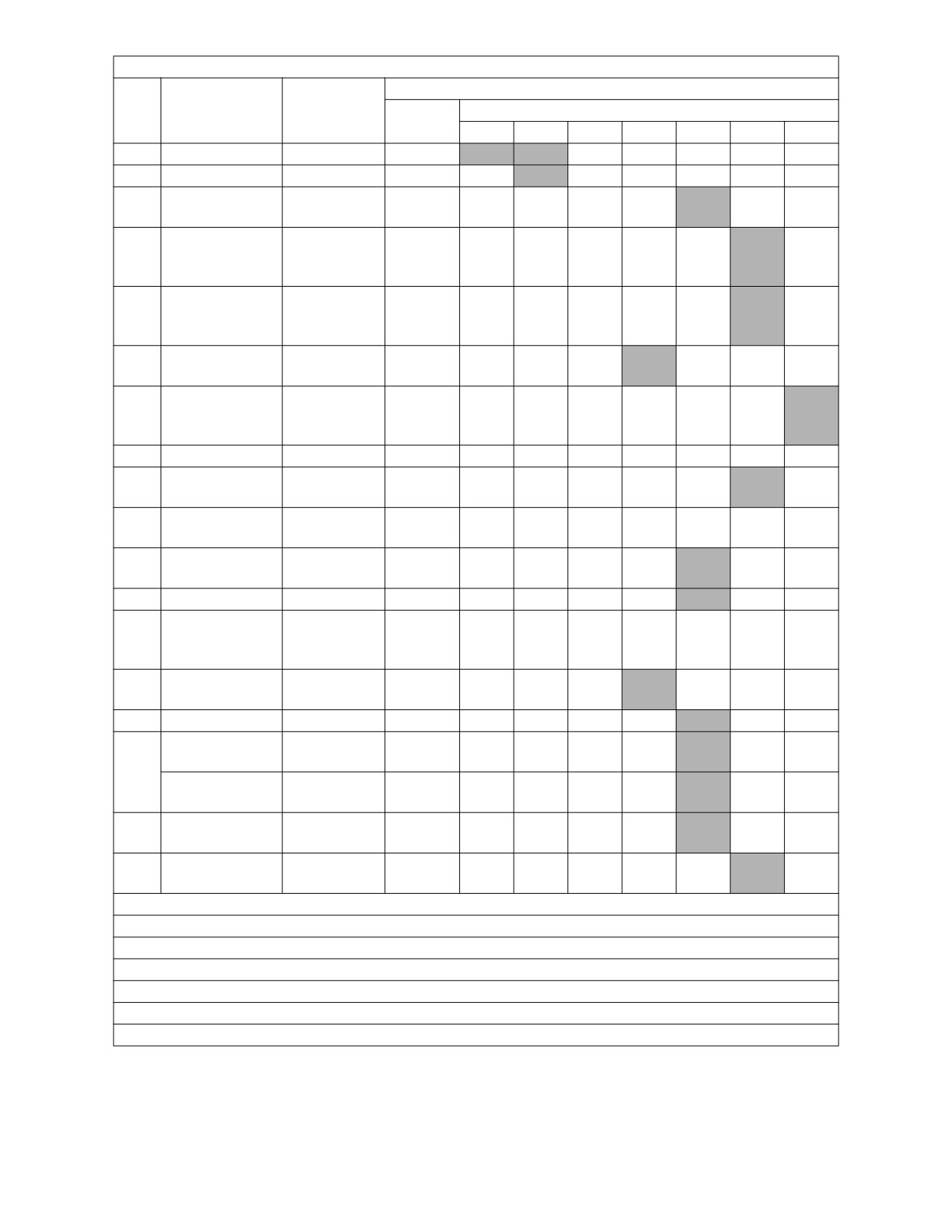
SERVICE DATA
S255LC-V
Items To
No.
Service
Service Interval
Check
Qty.
10
50
150
250
500
1000
2000
1
Front Joint Pin
Grease
19
F100
W10
2
Swing Bearing
Grease
3
Swing Gear
3
Grease
1
and Pinion
Swing
Gear Oil
4
Reduction
11 L
V
F
(80W90)
Device
Travel
Gear Oil
5
Reduction
2X5 L
V, F
(80W90)
Device
Engine Oil
6
Engine Oil
21 L
V
F
(15W40)
Hydraulic
7
Hydraulic Oil
Oil (Equivis
290 L
V
46)
8
Fuel Tank
Diesel
370 L
V
Coolant
9
Radiator
36 L
V
(Antifreeze)
Water
10
1
V
Separator
Hydraulic Full-
11
Element
1
F
flow Filter
12
Pilot filter
Element
1
F
Hydraulic Oil
13
Suction
Strainer
1
C
Strainer
Engine Oil
14
Cartridge
1
F
Filter
15
Fuel Filter
Cartridge
1
V
Air Cleaner
Element
1
C
(Outer)
16
Air Cleaner
Element
1
(Inner)
Air Conditioner
17
Element
1
Filter
Coolant
Coolant
18
1
V
Recovery Tank
(Antifreeze)
V: Maintenance & Refill.
C: Cleaning.
F: First Time Exchange Only.
F100: Every 10 Hours For First 100 Hours.
W10: Every 10 Hours If Operating In Water.
Gray Box: Replacement On Every Interval.
NOTE: For additional service items see list of “Maintenance Intervals” on page 4-10.
022-00031E Operation and Maintenance Manual
Inspection, Maintenance and Adjustment 4-9
MAINTENANCE INTERVALS
10 HOUR / DAILY SERVICE
•
Grease Boom, Arm and Front Attachment
•
Inspect the Bucket Teeth and Side Cutters
Pins (for first 100 hours) (See page 4-12)
for Signs of Wear (See page 4-19)
•
Check Engine Oil Level (See page 4-12)
•
Inspect Engine Fan Blade (See page 4-19)
•
Check Level of Hydraulic Oil Tank (See page
•
Check Air Intake System (See page 4-20)
4-13)
•
Inspect Seat Belt for Proper Operation (See
•
Check for Leaks in the Hydraulic System
page 4-20)
(See page 4-14)
•
Inspect the Structure for Cracks and Faulty
•
Check Fuel Level (See page 4-15)
Welds (See page 4-20)
•
Check for Leaks in the Fuel System (See
•
Check the Operation of All Switches (See
page 4-15)
page 4-20)
•
Check Water Separator and Drain Water As
•
Check the Operation of All Exterior Lights,
Required (See page 4-16)
Horn and Control Console Indicator and
•
Check Oil Level of Swing Reduction Device
Monitor Lights (See page 4-20)
(See page 4-17)
•
Start Engine, Check Starting Ability, and
•
Clean Dust Net in Front of Oil Cooler (See
Observe Exhaust Color at Start-up and at
page 4-18)
Normal Operating Temperature. Listen for
•
Check Cooling System and Refill As
Any Abnormal Sounds (See page 4-21)
Required (See page 4-18)
•
Check Operation of All Controls (See page
•
Check Level of Window Washer Liquid (See
4-21)
page 4-19)
50 HOUR / WEEKLY SERVICE
•
Perform All 10 Hour / Daily Service Checks
•
Check Engine Fan Belt for Cracks, Wear and
(See page 4-22)
Correct Tension (After First 50 Hours) (See
•
Grease Boom, Arm and Front Attachment
page 4-25)
Pins (See page 4-22)
•
Change Engine Oil and Filter (After First 50
•
Grease Swing Bearing (See page 4-24)
Hours) (See page 4-25)
•
Drain Water and Sediment from Fuel Filter
•
Inspect the Track Assemblies for Proper
(See page 4-25)
Tension and Loose, Worn or Damaged Parts
•
Drain Water and Sediment from Fuel Tank
(Links, Shoes, Rollers, Idlers) (See page
(See page 4-25)
4-25)
250 HOUR / MONTHLY SERVICE
•
Perform All 10 hour / daily and 50 Operating
•
Change Oil in Travel Reduction Device (One
Hour Service Checks (See page 4-26)
on Each Side of Unit) (After First 250 Hours)
•
Change Swing Reduction Device Oil (Drain
(See page 4-30)
and Refill After First 250 Hours) (See page
•
Replace Full Flow Hydraulic Oil Filter (After
4-26)
First 250 Hours) (See page 4-30)
•
Clean Outer Element of Two Stage Air
•
Change Pilot Filter (After First 250 Hours)
Cleaner (See page 4-26)
(See page 4-30)
•
Check Engine Fan Belt Tension (See page
•
Inspect Pins and Bushings of the Front End
4-27)
Attachments for Signs of Wear (See page
•
Check Engine Fan Belt Wear (See page
4-30)
4-28)
•
Check Fluid Levels in Batteries and Battery
•
Change Engine Oil and Filter (See page
Charge Levels (See page 4-30)
4-29)
•
Inspect for Any Loose or Missing Nuts and
•
Check Oil Level In Travel Reduction Device
Bolts (See page 4-30)
(One on Each Side of Unit) (See page 4-30)
•
Inspect Fuel System Hose Clamps (See
page 4-30)
4-10 Inspection, Maintenance and Adjustment
022-00031E Operation and Maintenance Manual
500 HOUR / 3 MONTH SERVICE
•
Perform All Daily (10 Hour), 50, and 250
•
Clean Air Conditioning Filter (See page
Operating Hour Service Checks (See page
4-34)
4-31)
•
Clean Radiator, Oil Cooler, Intercooler and
•
Grease Swing Gear and Pinion (See page
Air Conditioner Condenser Core (See page
4-31)
4-35)
•
Replace Full Flow Hydraulic Oil Filter (See
•
Replace Outer and Inner Air Cleaner
page 4-32)
Elements (See page 4-36)
•
Change Pilot Filter (See page 4-33)
•
Change Fuel Filter (See page 4-37)
1000 HOUR / 6 MONTH SERVICE
•
Perform All Daily (10 Hour), 50, 250 and 500
•
Change Radiator Coolant (See page 4-41)
Operating Hour Service Checks (See page
•
Clean Fuel Injection Priming Pump Strainer
4-39)
(See page 4-43)
•
Change Swing Reduction Device Oil (See
•
Check Air Conditioner Refrigerant (See
page 4-39)
page 4-43)
•
Change Oil in Travel Reduction Device (One
•
Check and Adjust Engine ** (See page 4-44)
on Each Side of Unit) (See page 4-40)
2000 HOUR / YEARLY SERVICE
•
Perform All Daily, 50, 250, 500 and 1,000
•
Inspect Machine to Check for Cracked or
Operating Hour Service Checks (See page
Broken Welds or other Structural Damage
4-45)
(See page 4-45)
•
Check Alternator and Starter** (See page
•
Check, Adjust Valve Clearance ** (See page
4-45)
4-45)
•
Check All Rubber Anti-vibration Shock
•
Check Head Bolt Torques (See page 4-45)
Mounts (See page 4-45)
•
Hydraulic Oil Exchange and Suction Strainer
•
Perform and Record the Results of the Cycle
Cleaning (See page 4-45)
Time Tests (See page 4-45)
4000 HOUR / BIENNIAL SERVICE
•
Major Parts - Periodic Replacement (See
page 4-48)
12,000 HOUR / SIX YEAR SERVICE
•
Hose In-service Lifetime Limit (European
Standard ISO 8331 and EN982 CEN) (See
page 4-49)
** These checks need to be completed by an authorized Daewoo dealer.
022-00031E Operation and Maintenance Manual
Inspection, Maintenance and Adjustment 4-11
10 HOUR / DAILY SERVICE
GREASE BOOM, ARM AND FRONT ATTACHMENT PINS (FOR FIRST 100 HOURS)
Grease every 10 hours for first 100 hours and every 50 hours thereafter. (See page 4-22)
NOTE: If the unit has been running or working in water the front attachment should be greased on
a 10 hour / Daily basis.
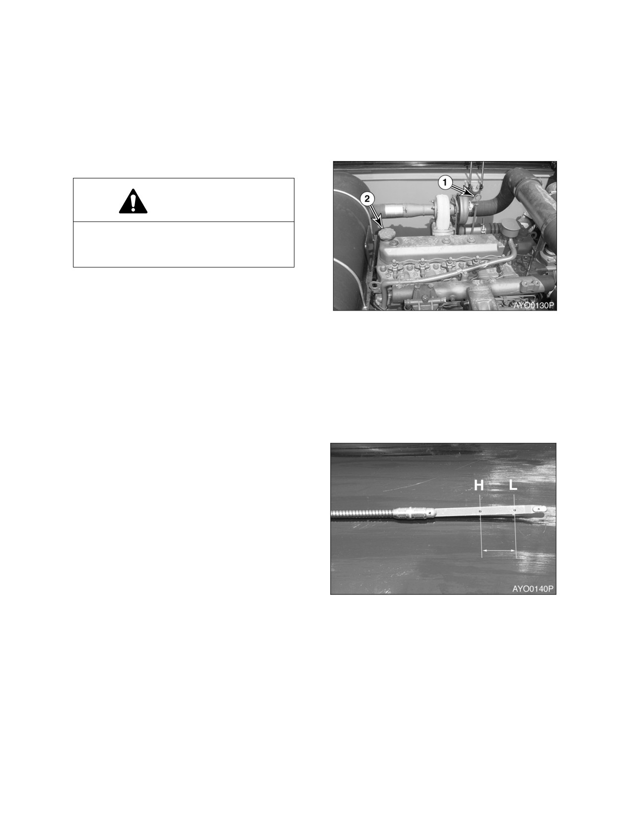
CHECK ENGINE OIL LEVEL
WARNING!
Allow the engine to cool before checking
the oil level to avoid burns by touching hot
engine parts.
NOTE: When checking level using a
dipstick always remove and
wipe it clean before making
final level check.
Figure 11
1.
Shut down engine and wait for 15 minutes.
This will allow all oil to drain back to oil
pan.
2.
Remove dipstick (1, Figure 11) and wipe
the oil off with a clean cloth.
3.
Insert dipstick fully in the oil gauge tube,
then take it out again.
4.
Engine oil level must be between "HIGH"
and "LOW" marks on dipstick.
NOTE: If oil is above "HIGH" mark on
dipstick, some must be drained
to return oil to proper level.
5.
Add oil through engine oil fill cap (2, Figure
11), if the oil level is below the "LOW"
mark.
Figure 12
4-12 Inspection, Maintenance and Adjustment
022-00031E Operation and Maintenance Manual
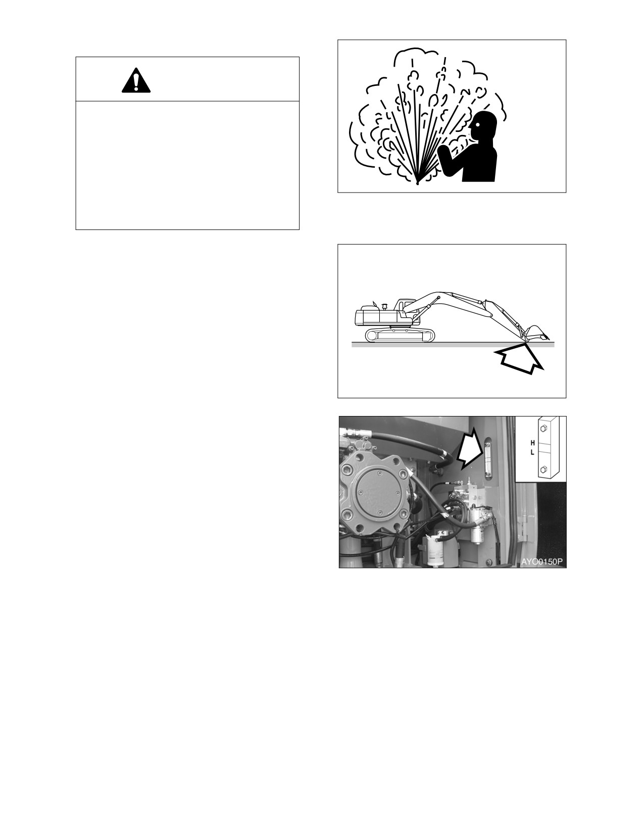
CHECK LEVEL OF HYDRAULIC OIL TANK
WARNING!
The hydraulic oil will be hot after normal
machine operation. Allow the system to
cool before attempting to service any of
the hydraulic components.
The hydraulic tank is pressurized. Turn
the breather cap slowly to allow the
ARO1760L
pressurized air to vent. After the pressure
Figure 13
has been released, it is safe to remove
either the fill cap or service covers.
1.
Position the machine on firm, level ground.
Lower boom and position bucket on
ground as shown in Figure 14.
2.
Set engine speed to "LOW IDLE."
HAOC360L
Figure 14
3.
Set safety lever to "LOCK" position.
4.
Check level gauge by opening right access
door. Oil level must be between marks on
sight gauge.
Figure 15
022-00031E Operation and Maintenance Manual
Inspection, Maintenance and Adjustment 4-13
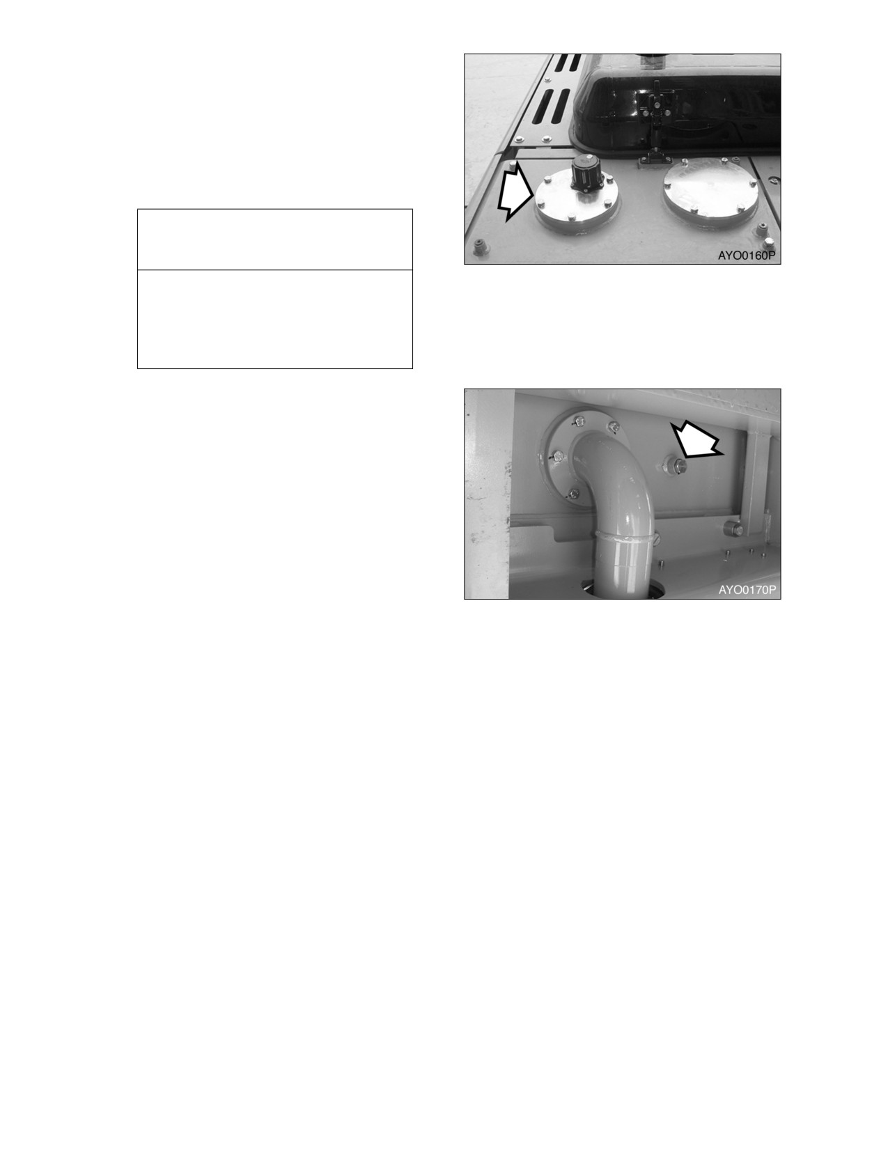
5.
If the level is below "L" mark add oil.
A. Shut down engine.
B. The hydraulic tank is pressurized.
Turn the breather cap slowly to allow
the pressurized air to vent.
C. Remove the upper cover of the
hydraulic tank and add oil.
IMPORTANT
Figure 16
Do not fill above "H" mark on sight
gauge. Overfilling can result in
damage to equipment and oil leaking
from hydraulic tank due to
expansion.
6.
If oil level is above the "H" mark drain oil.
A. Shut down engine and wait for the
hydraulic oil to cool down.
B. Drain the excess oil from drain plug
(Figure 17) at the bottom of the tank
into a suitable container.
NOTE: Dispose of drained fluids
according to local regulation.
CHECK FOR LEAKS IN THE HYDRAULIC
SYSTEM
Figure 17
1.
Perform a daily walk-around inspection to
make sure that the hoses, piping, fittings,
cylinders and hydraulic motors are not
showing any signs of leakage. If any is
noted, determine the source of the leak
and repair.
4-14 Inspection, Maintenance and Adjustment
022-00031E Operation and Maintenance Manual
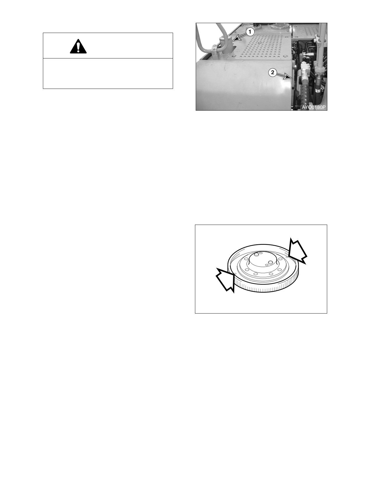
CHECK FUEL LEVEL
WARNING!
Use extreme safety precautions while
refueling to prevent explosions or fire.
Immediately clean up any spilt fuel.
1.
At end of each work day, fill fuel tank. Add
fuel through fuel filler tube (1, Figure 18).
When working at a temperature of 0°C
Figure 18
(32°F) or higher, use ASTM No. 2-D or its
equivalent. At temperatures below
0°C
(32°F) use ASTM No. 1-D or its equivalent.
2.
Make sure that the fuel fill hose is grounded to the excavator before fueling begins.
3.
Check the amount of fuel in the tank by observing the fuel tank sight gauge (2, Figure 18).
NOTE: See “Fluid Capacities” on page 4-7. for capacity.
4.
The excavator may be equipped with the optional battery operated fuel fill pump. The pump assembly
is in the hydraulic pump compartment. Put the suction hose of the pump into the fuel resupply tank.
Turn the switch in the battery box "ON," and the fuel will be pumped into the excavator fuel tank.
5.
Do not overfill the tank.
6.
Securely tighten cap after fueling.
NOTE: If breather holes in cap are
clogged, a vacuum may form in
the tank preventing proper fuel
flow to engine. Keep holes in
fuel cap clean.
CHECK FOR LEAKS IN THE FUEL SYSTEM
1.
Perform an inspection of the engine
compartment to verify that the fuel system
is not leaking. If any is noted, determine
the source of the leak and repair.
HAOC510L
Figure 19
022-00031E Operation and Maintenance Manual
Inspection, Maintenance and Adjustment 4-15
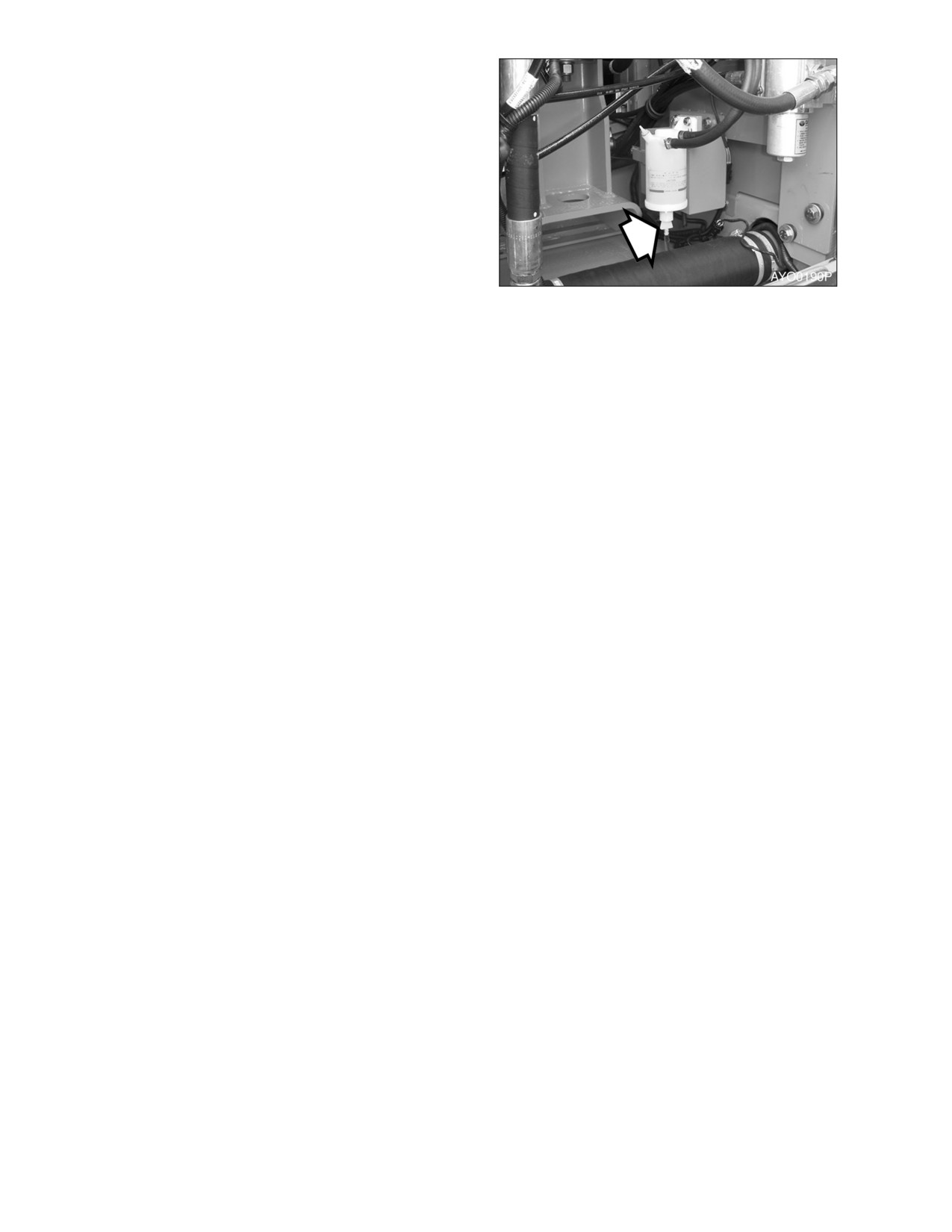
CHECK WATER SEPARATOR AND DRAIN
WATER AS REQUIRED
1.
A water separator is inside the right side
access door.
2.
Open the access door on right side of the
machine.
3.
If red ring in bowl reaches level line, loosen
plug (Figure 20) at bottom of body and
drain water into a suitable container.
NOTE: Dispose of drained fluids
according to local regulation.
Figure 20
4.
Tighten plug (Figure 20) and prime fuel
system. (See page 4-38)
5.
Close access door.
4-16 Inspection, Maintenance and Adjustment
022-00031E Operation and Maintenance Manual
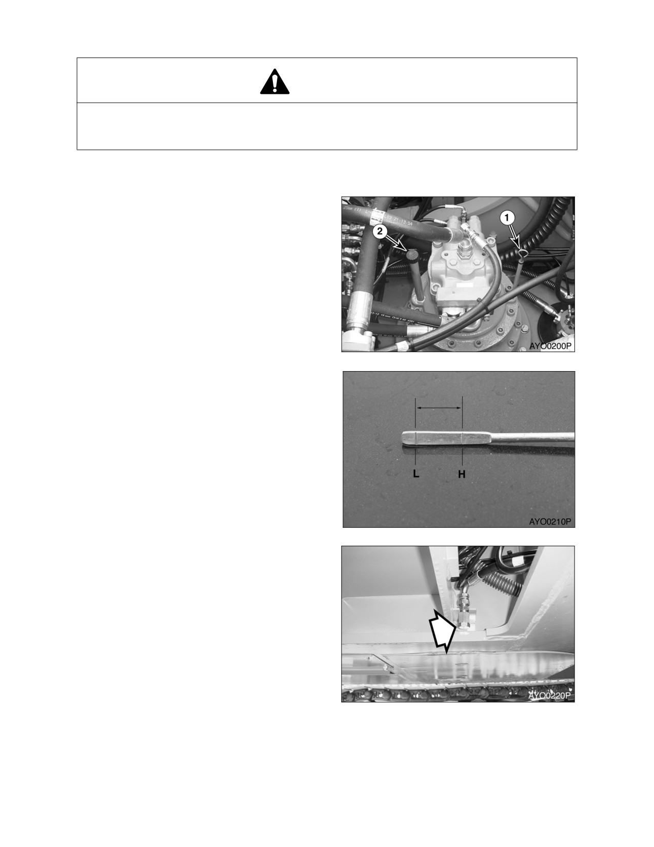
CHECK OIL LEVEL OF SWING REDUCTION DEVICE
WARNING!
The gear oil is very hot after the machine has been operating. Shut all systems down and allow
them to cool. Before fully removing any motor case inspection port plug, etc., loosen the plug
slightly to allow pressurized air to escape.
NOTE: When checking level using a dipstick always remove and wipe it clean before making final
level check.
1.
Remove dipstick (1, Figure 21) and wipe
the oil from the dipstick with a cloth.
2.
Insert dipstick (1, Figure 21) fully in the
guide.
Figure 21
3.
When dipstick is pulled out, oil level must
be between "HIGH" and "LOW" marks on
dipstick.
NOTE: If oil is above "HIGH" mark on
dipstick, some must be drained
to proper level.
4.
If the oil does not reach the "L" mark on
the dipstick, add oil through fill port
(2,
Figure 21).
Figure 22
5.
If the oil level exceeds the "H" mark on the
dipstick, remove drain plug (Figure 23) and
drain the excess oil into a suitable
container.
NOTE: Dispose of drained fluids
according to local regulations.
Figure 23
022-00031E Operation and Maintenance Manual
Inspection, Maintenance and Adjustment 4-17
CLEAN DUST NET IN FRONT OF OIL
COOLER
IMPORTANT
If running excavator in dusty area, check
dust net everyday and clean it if dirty.
WARNING!
Figure 24
If using compressed air or water to clean
the dust net, make sure that proper eye
protection is worn.
1.
Loosen the wing nut(s) and remove dust
net.
2.
Clean with compressed air or a water.
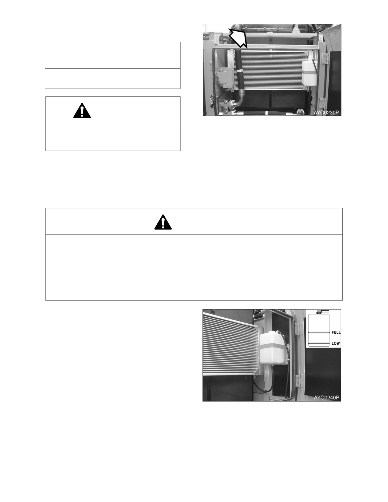
CHECK COOLING SYSTEM AND REFILL AS REQUIRED
WARNING!
Allow the engine to cool before releasing the radiator cap. Make sure to loosen the cap slowly to
release any remaining pressure.
Radiator cleaning is performed while the engine is running. Take extreme caution when working
on or near a running engine. Make sure to lock out and tag the controls notifying personnel that
service work is being performed.
Do not remove the radiator cap unless it is required. Observe the coolant level in the coolant
recovery tank.
1.
When the engine is cold, remove the
radiator cap and check the coolant level
inside the radiator. Do not rely on the level
of coolant in the coolant recovery tank.
Refill radiator as required. Refer to coolant
concentration table. (See page 4-42)
2.
Check to make sure that the coolant
transfer line from the coolant recovery tank
to the radiator is free and clear of
obstructions, or not pinched.
3.
Observe the level of coolant in the coolant
recovery tank. The normal cold engine
Figure 25
fluid level should be between "FULL" and
"LOW" marks on tank.
4.
If the coolant is below the "LOW" mark,
add coolant to this tank.
4-18 Inspection, Maintenance and Adjustment
022-00031E Operation and Maintenance Manual
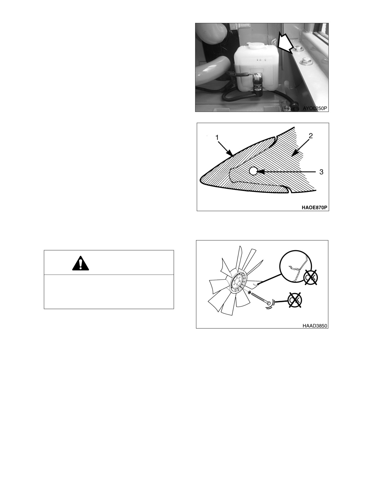
CHECK LEVEL OF WINDOW WASHER
LIQUID
1.
Open left front door and check fluid level in
windshield washer tank.
2.
Open fill cap and add fluid.
NOTE: Use a washer liquid that is rated
for all seasons. This will prevent
freezing during cold weather
operation.
Figure 26
INSPECT THE BUCKET TEETH AND SIDE
CUTTERS FOR SIGNS OF WEAR
1.
On a daily basis, inspect the bucket teeth
to make sure that tooth wear or breakage
has not developed.
2.
Do not allow the replaceable bucket teeth
to wear down to the point that the bucket
adapter is exposed. See Figure 27.
NOTE: These instructions are only for
Daewoo OEM buckets. If you
are using other manufacturers’
buckets, refer to their specific
Figure 27 1. POINT, 2. ADAPTER & 3. PIN
instructions.
INSPECT ENGINE FAN BLADE
WARNING!
Personal injury can result from a fan blade
failure. Never pull or pry on the fan. This
can damage the fan blade(s) and cause
fan failure.
NOTE: Manually rotate the crankshaft
by using a wrench on the
accessory drive pulley nut.
Figure 28
1.
An inspection of the cooling fan is required
daily. Check for cracks, loose bolts, bent or
loose blades, and for contact between the
blade tips and the fan shroud. Check the
fan to make sure it is securely mounted.
Tighten the bolts if necessary. Replace
any fan that is damage.
022-00031E Operation and Maintenance Manual
Inspection, Maintenance and Adjustment 4-19
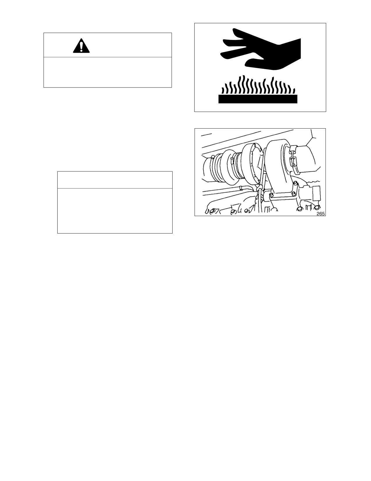
CHECK AIR INTAKE SYSTEM
CAUTION!
Hot engine components can cause burns.
Avoid contact with hot engine
components
1.
Park the machine on a level surface, lower
the attachment to the ground, set safety
HAOA050L
lever to "LOCK" position, and shut down
Figure 29
engine.
2.
Check the engine intake hose, and hose
bands for damage and tightness.
3.
If damaged, wrinkled or loose, replace or
retighten or contact your nearest Daewoo
dealer.
IMPORTANT
Severe engine damage will result
from running with unfiltered air.
Do not operate engine if any leaks or
defects are found on air intake
Figure 30
system.
INSPECT SEAT BELT FOR PROPER OPERATION
INSPECT THE STRUCTURE FOR CRACKS AND FAULTY WELDS
1.
During the daily walk-around inspection and when greasing the machine, look for any visible damage
to the machine. Repair or replace any damaged parts before operating the machine.
CHECK THE OPERATION OF ALL SWITCHES
1.
Verify the working condition of all switches before starting the engine.
CHECK THE OPERATION OF ALL EXTERIOR LIGHTS, HORN AND CONTROL CONSOLE
INDICATOR AND MONITOR LIGHTS
1.
Turn the engine starter switch to the ON position and observe all of the indicator lights.
2.
Restore operation of any light bulbs that do not turn on at this point.
3.
Sound the horn. Repair or replace if required.
4.
Turn on and inspect all exterior work lights. Replace any monitors, burned out bulbs or cracked or
broken housings or lenses.
4-20 Inspection, Maintenance and Adjustment
022-00031E Operation and Maintenance Manual
START ENGINE, CHECK STARTING ABILITY, AND OBSERVE EXHAUST COLOR AT START-UP
AND AT NORMAL OPERATING TEMPERATURE. LISTEN FOR ANY ABNORMAL SOUNDS
CHECK OPERATION OF ALL CONTROLS
IMPORTANT
Cold weather operation requires that the operator fully warm up the hydraulic oil before
beginning machine operation. Follow all warm up instructions listed in the Operating Instruction
section of this manual. Make sure to cycle oil through all of the components, including all
cylinders, both travel motors and the swing motor. Cold hydraulic oil in the lines and
components needs to be warmed before beginning full operation. If this is not done, damage to
the cylinders or hydraulic motors can occur.
1.
With the engine at rated speed, operate all of the controls.
2.
Follow cold weather hydraulic system warm-up procedures.
3.
Note any slow operations or unusual movements. Determine the cause and repair the fault before
operating.
022-00031E Operation and Maintenance Manual
Inspection, Maintenance and Adjustment 4-21
50 HOUR / WEEKLY SERVICE
PERFORM ALL 10 HOUR / DAILY SERVICE CHECKS
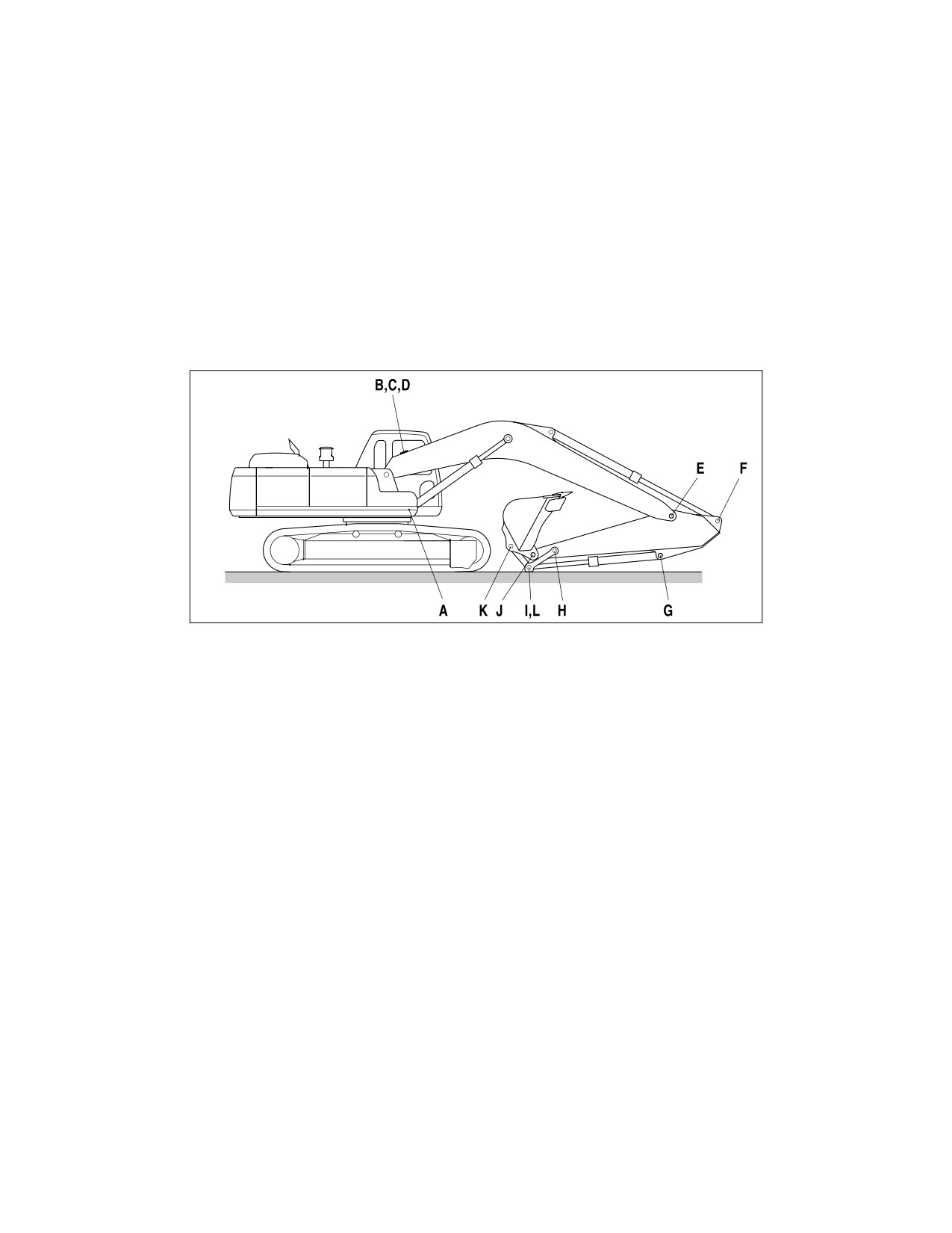
GREASE BOOM, ARM AND FRONT ATTACHMENT PINS
Grease every 10 hours for first 100 hours and every 50 hours thereafter.
NOTE: If the unit has been running or working in water the front attachment should be greased on
a 10 hour / Daily basis.
•
Position machine as shown below and lower front attachment to ground and shut down engine.
•
Press the grease fitting and inject grease with the grease gun on the marked point.
•
After injection, clean off the old grease that has been purged.
HAOC150L
Figure 31
A. BOOM CYLINDER FOOT PIN (2 POINTS)
G. BUCKET CYLINDER FOOT PIN (1 POINT)
B. BOOM FOOT PIN (2 POINTS)
H. ARM LINK JOINT PIN (2 POINTS)
C. BOOM CYLINDER ROD PIN (2 POINTS)
I.
LINK JOINT PIN (2 POINTS)
D. ARM CYLINDER FOOT PIN (1 POINT)
J.
ARM BUCKET JOINT PIN (2 POINTS)
E. BOOM ARM JOINT PIN (2 POINTS)
K.
BUCKET LINK JOINT PIN (1 POINT)
F.
ARM CYLINDER ROD (1 POINT)
L.
BUCKET CYLINDER ROD (1 POINT)
4-22 Inspection, Maintenance and Adjustment
022-00031E Operation and Maintenance Manual
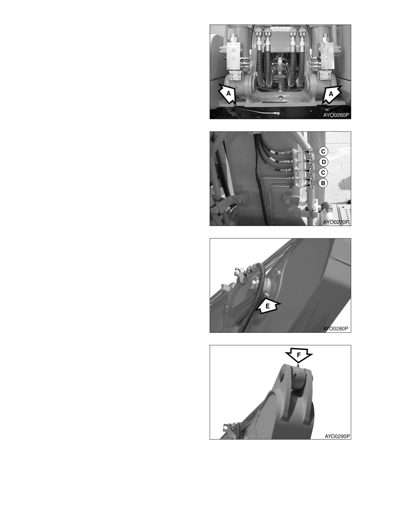
A. Boom cylinder foot pin (2 points)
Figure 32
B. Boom foot pin (2 points)
C. Boom cylinder rod pin (2 points)
D. Arm cylinder foot pin (1 point)
Figure 33
E. Boom arm joint pin (2 points)
Figure 34
F.
Arm cylinder rod (1 point)
Figure 35
022-00031E Operation and Maintenance Manual
Inspection, Maintenance and Adjustment 4-23
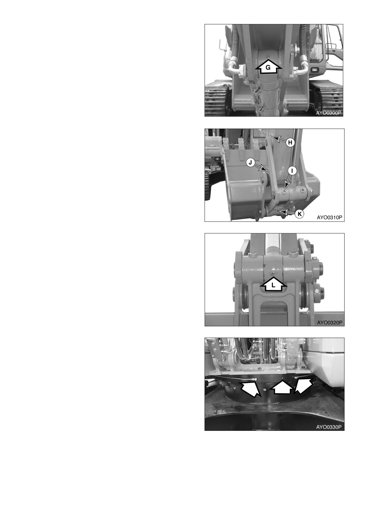
G. Bucket cylinder foot pin (1 point)
Figure 36
H. Arm link joint pin (2 points)
I.
Link joint pin (2 points)
J.
Arm bucket joint pin (2 points)
K. Bucket link joint pin (1 point)
Figure 37
L.
Bucket cylinder rod (1 point)
Figure 38
GREASE SWING BEARING
1.
Lower front attachment to ground.
2.
There are three grease fittings for the
swing bearing. Do not over lubricate.
Purge old grease with new. Remove all
purged grease.
Figure 39
4-24 Inspection, Maintenance and Adjustment
022-00031E Operation and Maintenance Manual
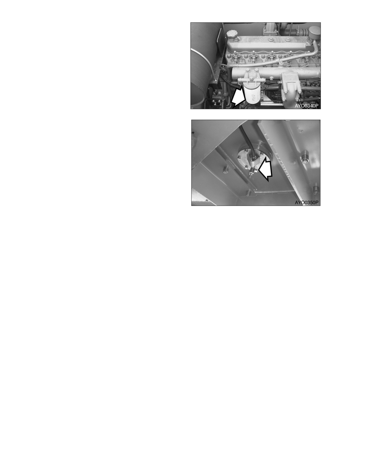
DRAIN WATER AND SEDIMENT FROM FUEL
FILTER
1.
Open drain valve on bottom of fuel filter
and drain water and sediment into a
suitable container.
NOTE: Dispose of drained fluids
according to local regulation.
Figure 40
DRAIN WATER AND SEDIMENT FROM FUEL
TANK
1.
Perform this procedure before operating
machine.
2.
Drain water and sediment from bottom of
fuel tank into a suitable container.
NOTE: Dispose of drained fluid
according to local regulations.
NOTE: Always completely fill fuel tank
at end of each workday to
prevent condensation from
Figure 41
forming on the inside walls of
the tank.
CHECK ENGINE FAN BELT FOR CRACKS, WEAR AND CORRECT TENSION (AFTER FIRST 50
HOURS)
1.
Inspect after first 50 hours of operation and every 250 hours thereafter. For details, See “Check
Engine Fan Belt Tension” on page 4-27.
CHANGE ENGINE OIL AND FILTER (AFTER FIRST 50 HOURS)
1.
Change engine oil and filter after first 50 hours of operation or rebuild, then every 250 thereafter. For
details, See “Change Engine Oil and Filter” on page 4-29.
INSPECT THE TRACK ASSEMBLIES FOR PROPER TENSION AND LOOSE, WORN OR DAMAGED
PARTS (LINKS, SHOES, ROLLERS, IDLERS)
1.
Do a daily walk-around inspection of all components including the track assemblies. Look for missing,
damaged or excessively worn parts. See “Track Tension” on page 4-64.
2.
Jack up each track and perform the two speed travel motor test.
022-00031E Operation and Maintenance Manual
Inspection, Maintenance and Adjustment 4-25
250 HOUR / MONTHLY SERVICE
PERFORM ALL 10 HOUR / DAILY AND 50 OPERATING HOUR SERVICE CHECKS
CHANGE SWING REDUCTION DEVICE OIL (DRAIN AND REFILL AFTER FIRST 250 HOURS)
NOTE: Change swing reduction device oil after first 250 hours on a new machine and every 1000
hours thereafter (See page 4-39).
CLEAN OUTER ELEMENT OF TWO STAGE AIR
CLEANER
02/05
[MO] 11:30A
WARNING!
2059 RPM
Never clean or attempt to remove the air
cleaner element if the engine is running.
Air Cleaner
If using compressed air to clean the
CLOGGED!!
element, make sure that proper eye
protection is worn.
ARO0210L
Figure 42
1.
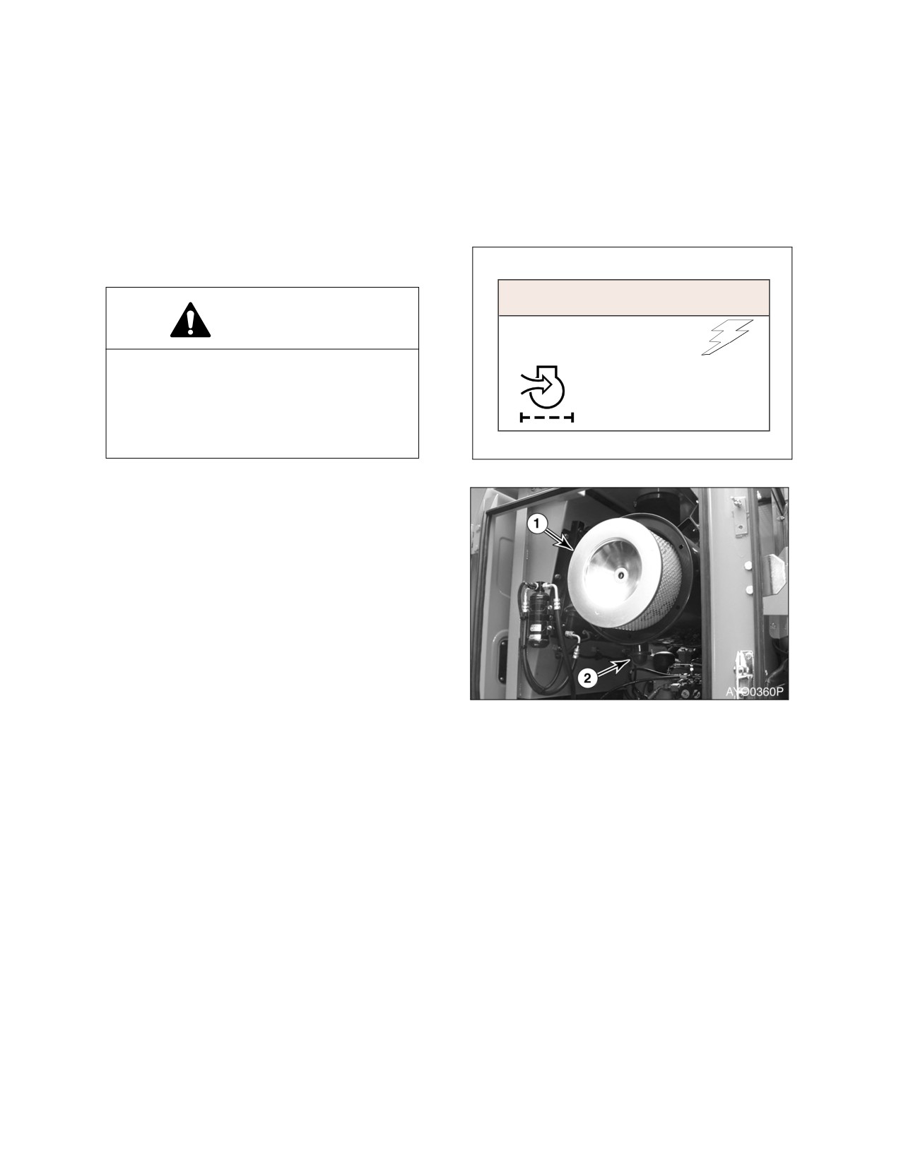
Locate the air filter assembly. Remove the
access cover and remove the outer
element
(1, Figure
43) of the air filter
assembly.
NOTE: If indicator light (Figure 42) on
instrument panel comes "ON"
the air cleaner must be
serviced.
NOTE: Replace outer element every
500 hours
/
3 months of
service.
2.
Remove and clean rubber evacuator valve
Figure 43
(2, Figure 43) from bottom of air cleaner
housing. Inspect seal lips for wear or
damage. Replace valve if necessary.
4-26 Inspection, Maintenance and Adjustment
022-00031E Operation and Maintenance Manual
3.
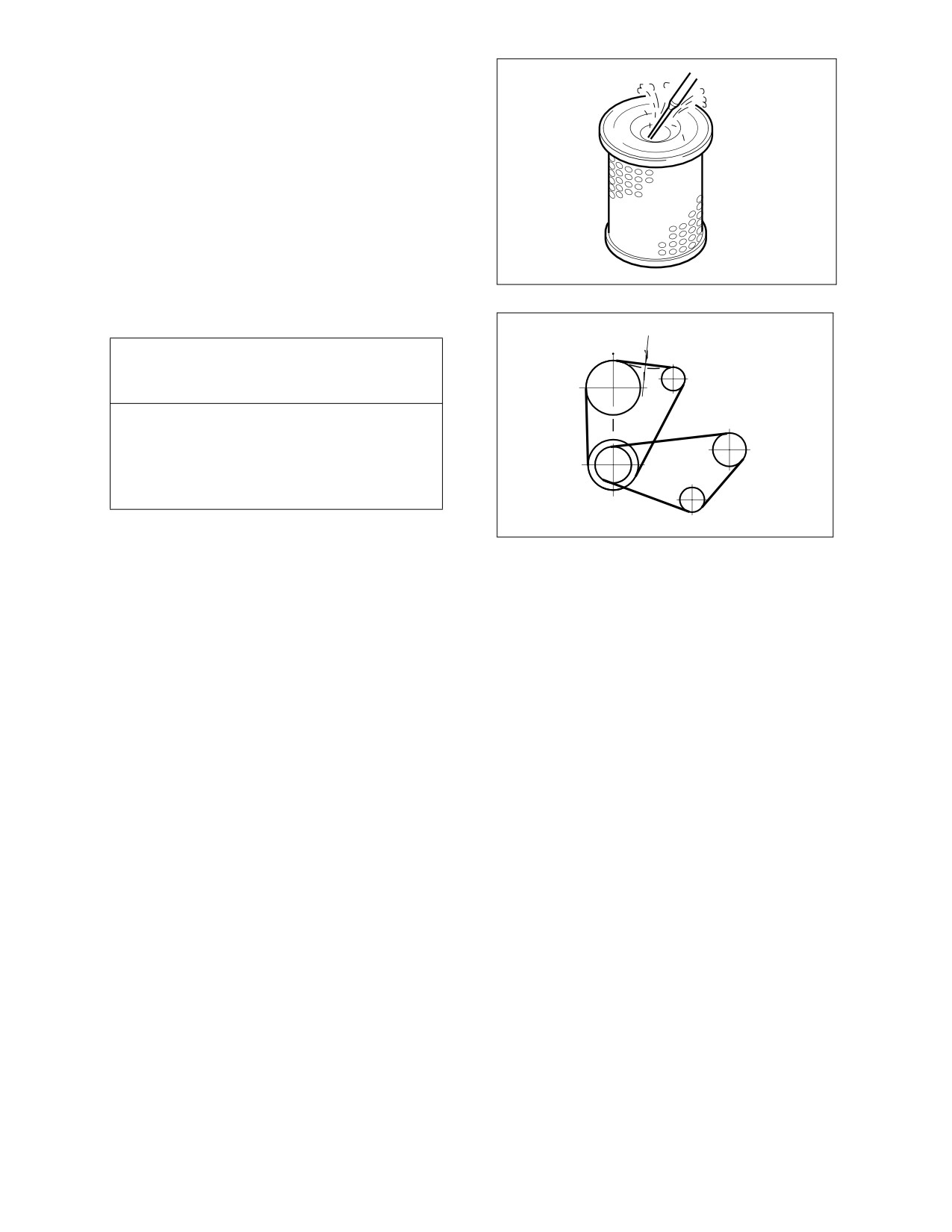
Clean the outer filter by blowing
compressed air from the inside of the filter
towards the outside. Do not use more than
205 kPa (30 psi) air pressure.
4.
Clean the inside of the air filter housing
and the inside of the air filter housing
cover.
5.
Properly reinstall the air filter and cover.
Tighten the cover wing nut finger tight. Do
not use any tools to tighten the wing nut.
HAOC570L
Figure 44
CHECK ENGINE FAN BELT TENSION
10mm /10kg
IMPORTANT
A loose fan belt can cause engine
overheating, poor charging, and/or
premature belt wear. A belt that is too tight
can cause damage to the water pump,
alternator bearing or belt.
HJB5001I
1.
Inspect every 250 hours. (Inspect after first
50 hours of operation.)
Figure 45
2.
With the engine shut off, check the tension
of the fan belt by pressing downwards on
the belt, midway between the fan pulley
and alternator pulley. The belt should flex
approximately
10 mm (0.500 in). See
Figure 45. To adjust the belt, loosen the
alternator adjustment plate bolts, adjust
the belt tension and retighten the bolts.
022-00031E Operation and Maintenance Manual
Inspection, Maintenance and Adjustment 4-27
CHECK ENGINE FAN BELT WEAR
WARNING!
Keep clear of engine fan and fan drive
belts when the engine is running. Rotating
fan and belt contact can cause injury.
WARNING!
Figure 46
When checking, adjusting or replacing
drive belts, care must be taken to prevent
accidental cranking of the engine. Be sure
the starter switch is in the "OFF" position
and the controls are tagged.
1.
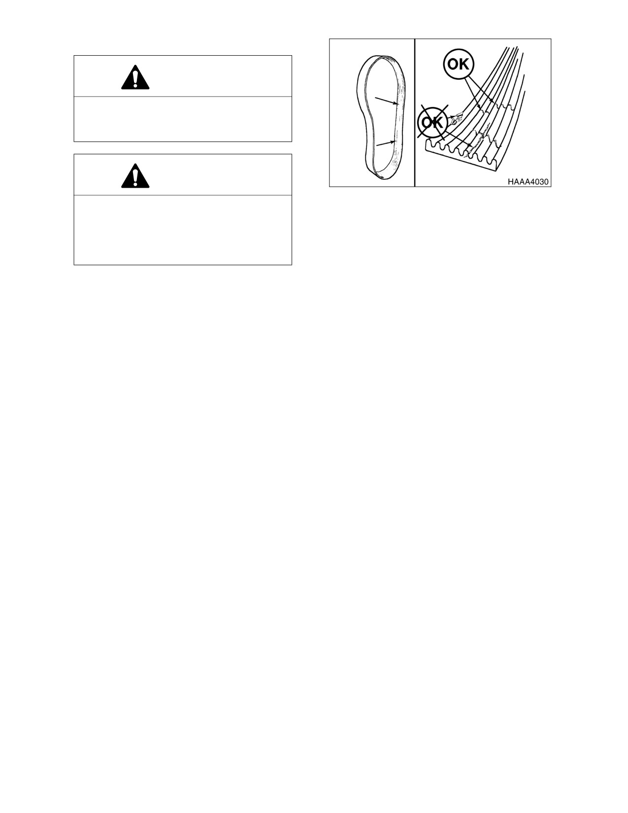
Replace badly worn, greasy or severely cracked belts immediately. These conditions prevent proper
belt function. Visually inspect the belt. Check the belt for intersecting cracks. Transverse (across the
belt width) cracks are acceptable. Longitudinal (direction of belt length) cracks that intersect with
transverse cracks are not acceptable. Replace the belt if it is frayed or has pieces of material missing.
2.
Before installing new belts, make sure all pulley grooves are clean and not worn. Replace pulley, if
damaged, or if the grooves are worn.
3.
All pulley support bearings, shafts, and brackets must be in working order.
4.
When replacing belts and pulleys, pulley alignment must be checked with belts tensioned and
brackets securely clamped. A misalignment that can be detected by the naked eye is detrimental to
belt performance.
5.
Do not force the belts into the pulley grooves by prying with a screwdriver or pry bar. This will damage
the belt side cords which will cause the belts to turn and result in complete destruction of the belts in
operation.
6.
Belts on new machines and replacement belts lose their tension as they seat into the pulley grooves.
Check the tension of new belts at 50 hour intervals until tension is stabilized and thereafter, every 250
hours. If the tension falls below the required minimum, the belt slips damaging the belts and pulley
grooves.
NOTE: When operating in abrasive conditions, check tension every 100 hours.
4-28 Inspection, Maintenance and Adjustment
022-00031E Operation and Maintenance Manual
CHANGE ENGINE OIL AND FILTER
NOTE: Change engine oil and filter after first 50 hours of operation or rebuild, then every 250
thereafter.
WARNING!
DO NOT change oil on a hot engine. Allow the engine to cool down before attempting to change
the engine oil and filter to avoid burns by touching hot engine parts.
1.
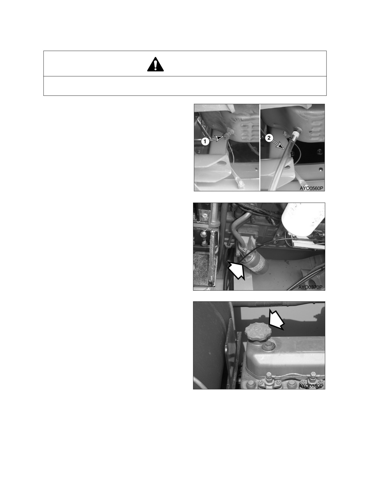
Position a larger container under the
engine. Remove cap (1, Figure 47) and
install hose
(2) to drain the engine oil.
Remove hose (2) and install cap (1).
NOTE: Dispose of drained fluids
according to local regulation.
Figure 47
2.
Replace engine oil filter by using filter
wrench. The engine oil filter is a spin-on
type. See Figure 48. Remove and discard
filter.
3.
Install new filter. Apply a small amount of
oil around filter gasket. Screw filter on
head until gasket contacts head, turn filter
1/2 turn more.
Figure 48
4.
Refill the engine with the correct oil
through the oil fill port (Figure 49). Refer to
the Lubrication Table of this manual for the
recommended oil for the operating
conditions.
NOTE: See
“Fluid Capacities” on
page 4-7. for capacity.
5.
Start engine and check engine oil pressure
light.
6.
Shut down engine. Look for signs of leaks
at filter. Recheck oil level.
Figure 49
022-00031E Operation and Maintenance Manual
Inspection, Maintenance and Adjustment 4-29
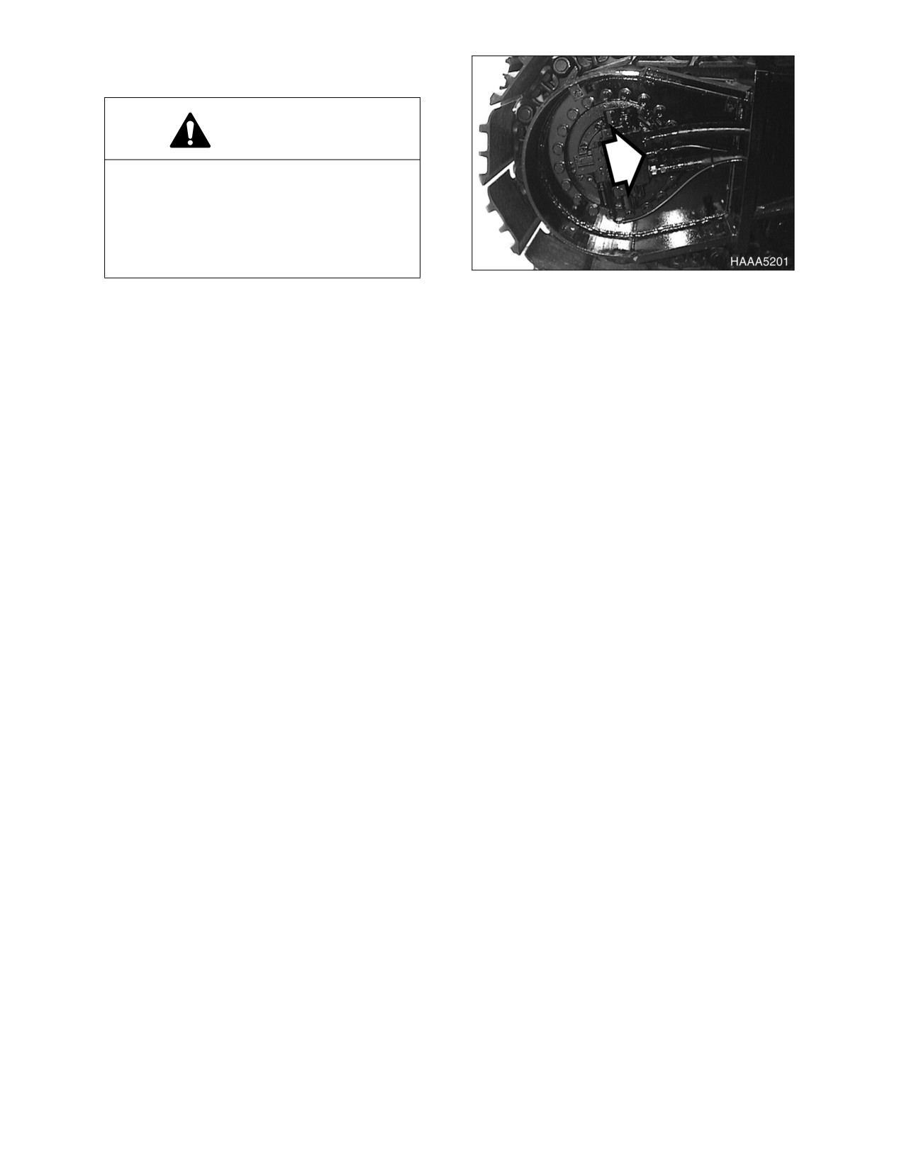
CHECK OIL LEVEL IN TRAVEL REDUCTION
DEVICE (ONE ON EACH SIDE OF UNIT)
WARNING!
The gear oil is very hot after the machine
has been operating. Shut all systems
down and allow them to cool. Before fully
removing any motor case inspection port
plug, etc., loosen the plug slightly to allow
pressurized air to escape.
Figure 50
1.
Make sure that the machine is on a firm,
level work area.
2.
Rotate the track until ports (1 and 2, Figure 50) are in their proper positions as shown.
3.
Remove oil level plug (1, Figure 50).
4.
Check oil level. The oil should be near the bottom of the level plug opening.
5.
Add oil through the level plug opening, if necessary.
6.
Clean and install oil level plug (1, Figure 50).
7.
Repeat this procedure on the other travel reduction device.
CHANGE OIL IN TRAVEL REDUCTION DEVICE (ONE ON EACH SIDE OF UNIT) (AFTER FIRST 250
HOURS)
NOTE: Drain and refill oil after first 250 hours of operation and every 1000 hours thereafter (See
page 4-40).
REPLACE FULL FLOW HYDRAULIC OIL FILTER (AFTER FIRST 250 HOURS)
NOTE: Replace full flow hydraulic oil filter after first 250 hours of operation or rebuild, then every
500 hours thereafter (See page 4-32).
CHANGE PILOT FILTER (AFTER FIRST 250 HOURS)
NOTE: Change pilot filter after first 250 hours and every 500 hours thereafter (See page 4-33).
INSPECT PINS AND BUSHINGS OF THE FRONT END ATTACHMENTS FOR SIGNS OF WEAR
CHECK FLUID LEVELS IN BATTERIES AND BATTERY CHARGE LEVELS
INSPECT FOR ANY LOOSE OR MISSING NUTS AND BOLTS
INSPECT FUEL SYSTEM HOSE CLAMPS
4-30 Inspection, Maintenance and Adjustment
022-00031E Operation and Maintenance Manual
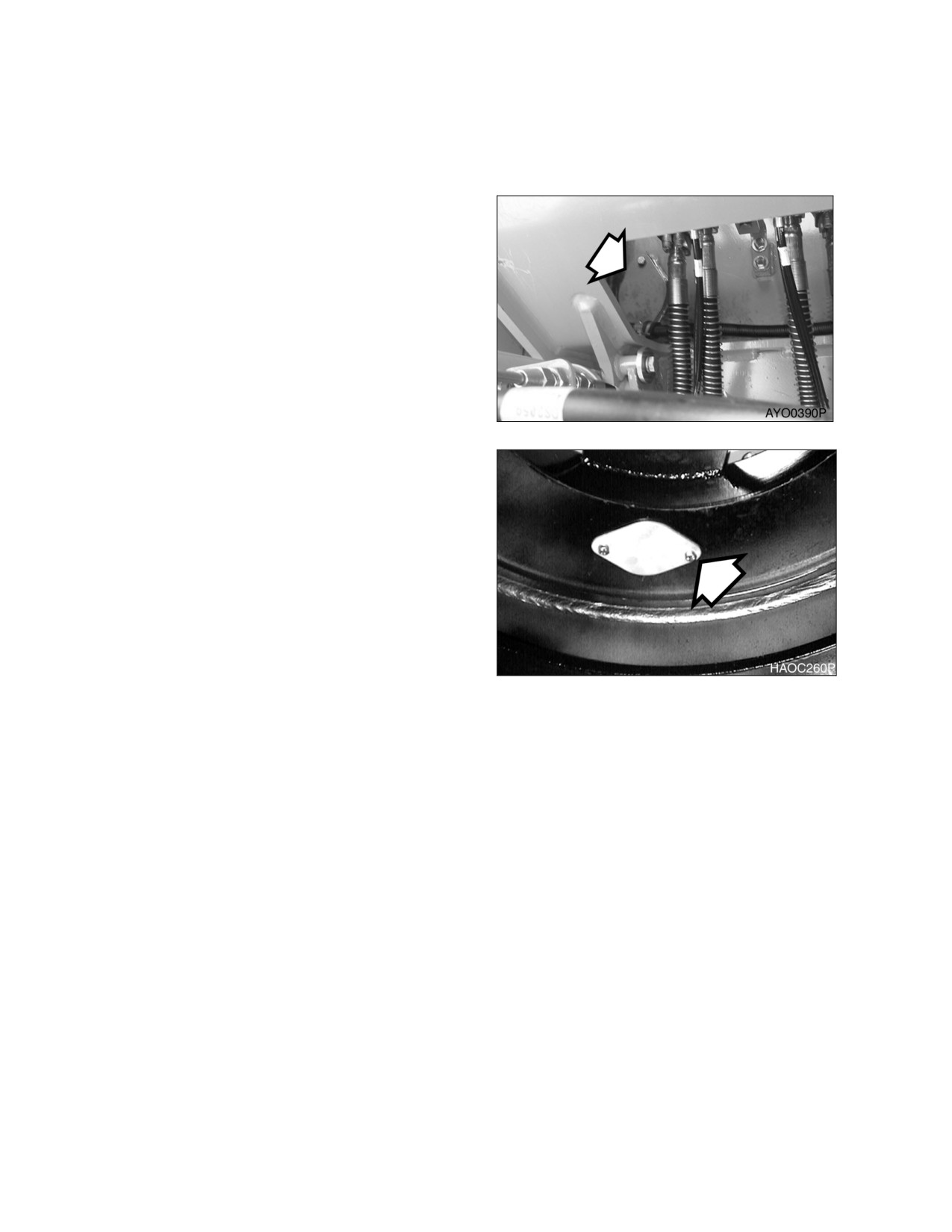
500 HOUR / 3 MONTH SERVICE
PERFORM ALL DAILY (10 HOUR), 50, AND 250 OPERATING HOUR SERVICE CHECKS
GREASE SWING GEAR AND PINION
1.
Remove inspection cover and inspect the
condition of the grease. Make sure that
water or other contaminants are not
noticeable.
NOTE: The upper structure must be
rotated a little at a time so that
the entire face of the swing gear
can be lubricated. Use extreme
caution when performing this
operation.
Figure 51
2.
If water or other contaminations are found,
remove the lower access cover so that the
gear teeth can be thoroughly cleaned and
lubricated.
3.
Install access covers after lubricating gear
teeth.
Figure 52
022-00031E Operation and Maintenance Manual
Inspection, Maintenance and Adjustment 4-31
REPLACE FULL FLOW HYDRAULIC OIL FILTER
NOTE: Change full flow hydraulic oil filter after first 250 hours of operation and every 500 hours
thereafter.
WARNING!
The hydraulic oil will be hot after normal machine operation. Allow the system to cool before
attempting to service any of the hydraulic components.
The hydraulic tank is pressurized. Loosen the hydraulic air breather cap slightly to allow the
pressurized air to vent. After the pressure has been released, it is safe to remove either the fill
cap or service covers or drain water from the tank.
IMPORTANT
Make sure to clean any dirt or water from the top of the hydraulic tank, especially around the fill
port and filter ports.
1.
Position the machine on firm, level ground.
Lower front attachment to ground and shut
down engine.
2.
Loosen the air breather cap slightly to
release the internal pressure.
3.
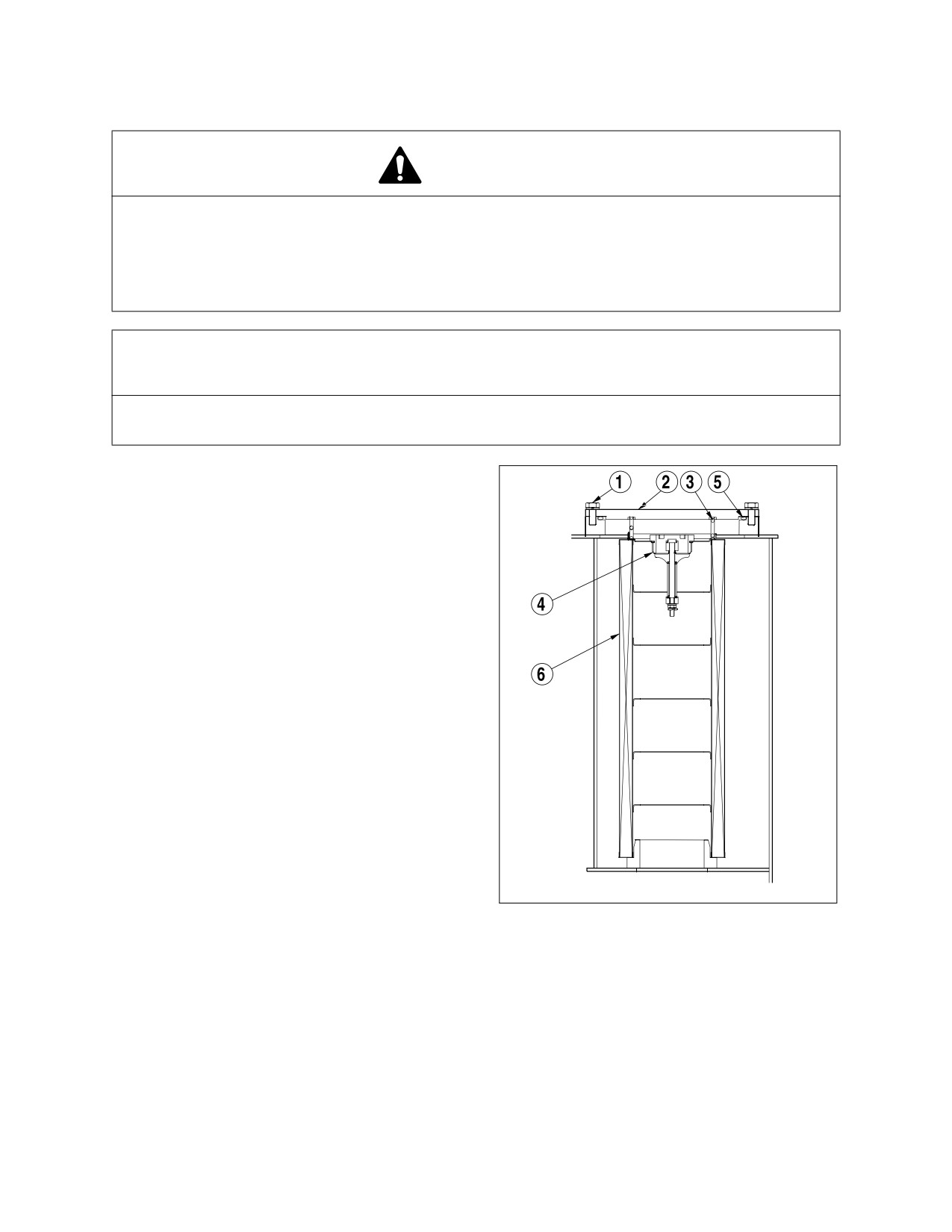
Remove bolts (1, Figure 53) and service
cover (2). Remove spring (3), valve (4) and
O-ring (5) from filter element (6).
4.
Remove filter element and properly
discard.
5.
Install new filter element and a new O-ring.
Install valve and spring. Install service
cover plate.
6.
Run engine for 10 minutes at low idle to
purge air from circuit.
7.
Shut down engine.
8.
Check level in hydraulic oil tank. Add oil if
necessary
HAOC460P
Figure 53
4-32 Inspection, Maintenance and Adjustment
022-00031E Operation and Maintenance Manual
CHANGE PILOT FILTER
NOTE: Change pilot filter after first 250
hours of operation and every
500 hours thereafter.
WARNING!
The hydraulic oil will be hot after normal
machine operation.
Allow the system to cool down before
changing pilot filter.
Figure 54
1.
Position the machine on the firm, level
ground. Lower front attachment to ground
and shut down engine.
2.
Loosen the air breather cap slightly to
release the internal pressure.
3.
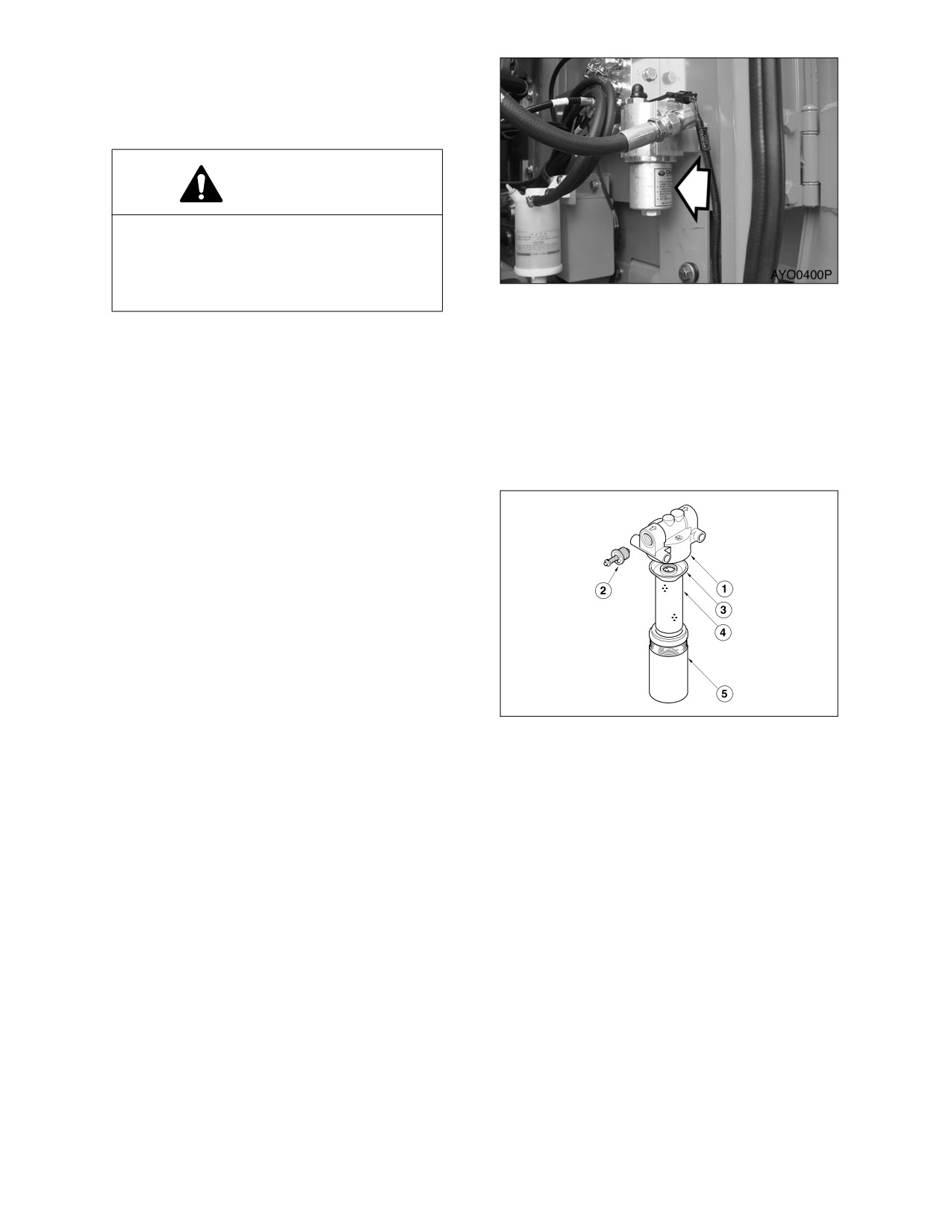
Locate pilot system filter assembly. See
Figure 54.
4.
Unscrew canister
(5, Figure
55) and
remove O-ring (3) and filter cartridge (4).
NOTE: The canister will be filled with
oil. Use caution when removing
this assembly.
5.
Insert a new filter cartridge and O-ring.
Apply a small amount of oil around the
entire O-ring and reinstall the canister
assembly onto the filter head (1, Figure
55).
6.
After changing pilot filter, vent air from
HAOC480L
pump and check level of hydraulic oil tank.
Figure 55
022-00031E Operation and Maintenance Manual
Inspection, Maintenance and Adjustment 4-33
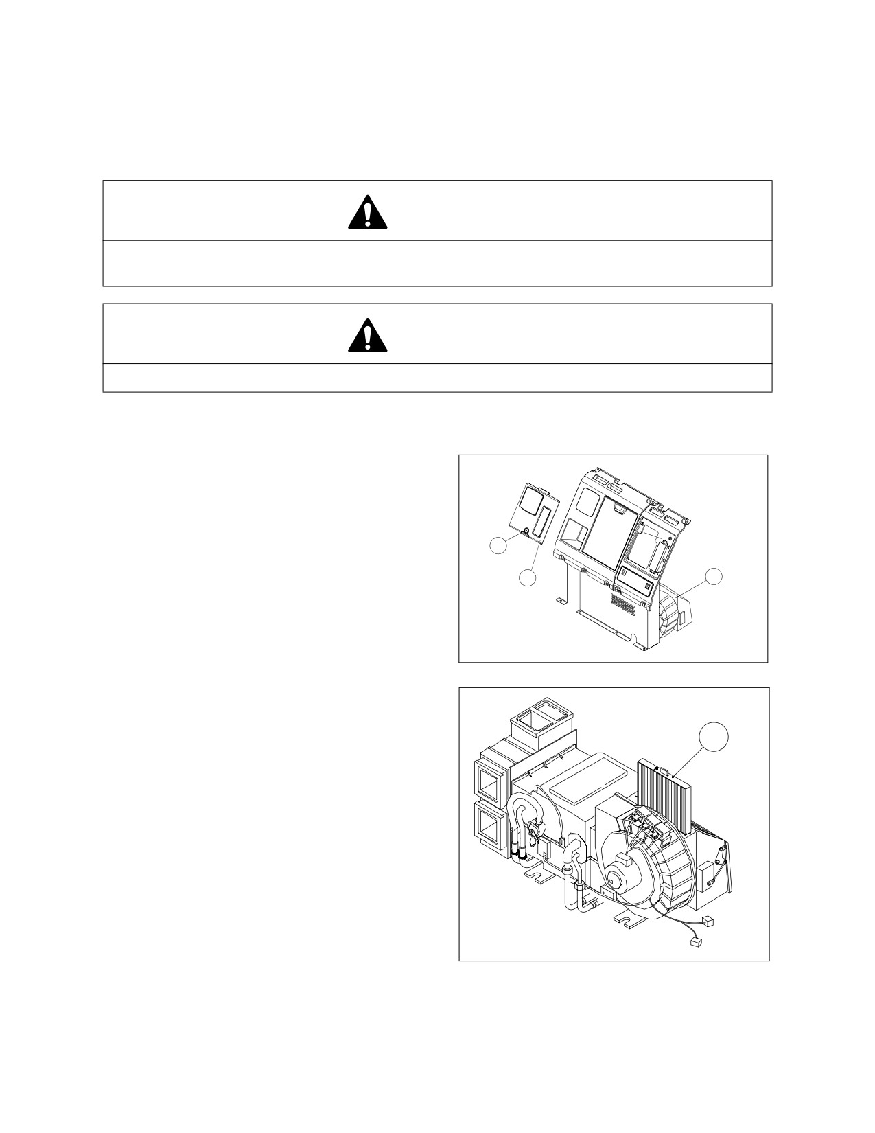
CLEAN AIR CONDITIONING FILTER
The unit is equipped with an air filtration system which filters out dirt and dust particles from air being
circulated into operator’s cab. This filter should be cleaned out.
NOTE: In the event that the unit is being operated in a dusty environment, the cleaning and
replacement should be performed more frequently. If filter element is damaged, replace
damaged filter by a new one.
WARNING!
All service and inspection of air conditioning system should be performed with the starter
switch in the "O" (OFF) position.
WARNING!
If using compressed air to clean the element, make sure that proper eye protection is worn.
NOTE: All right and left call outs are based on the operator being seated in the operator’s seat
facing the front.
1.
Turn the key cylinder (1, Figure 56) to open
cover
(2, Figure
56) behind operator’s
seat.
2.
Disconnect speaker harness.
3.
Remove cover (2, Figure 56) from the rear
1
box.
2
3
4.
Remove filter cover (3, Figure 56) from air
conditioning unit.
HAAD3860
Figure 56
5.
Remove filter element (1, Figure 57) and
inspect for any damage.
6.
Use compressed air to clean filter element.
1
If filter element is very dirty use a mild
soap or detergent and water to clean it.
NOTE: If water was used to clean filter,
be certain it is completely dry
before installing.
NOTE: When assembling the filter
again, install so that the arrow
on top of filter is facing the
inside of the cab.
HAOO790L
Figure 57
4-34 Inspection, Maintenance and Adjustment
022-00031E Operation and Maintenance Manual
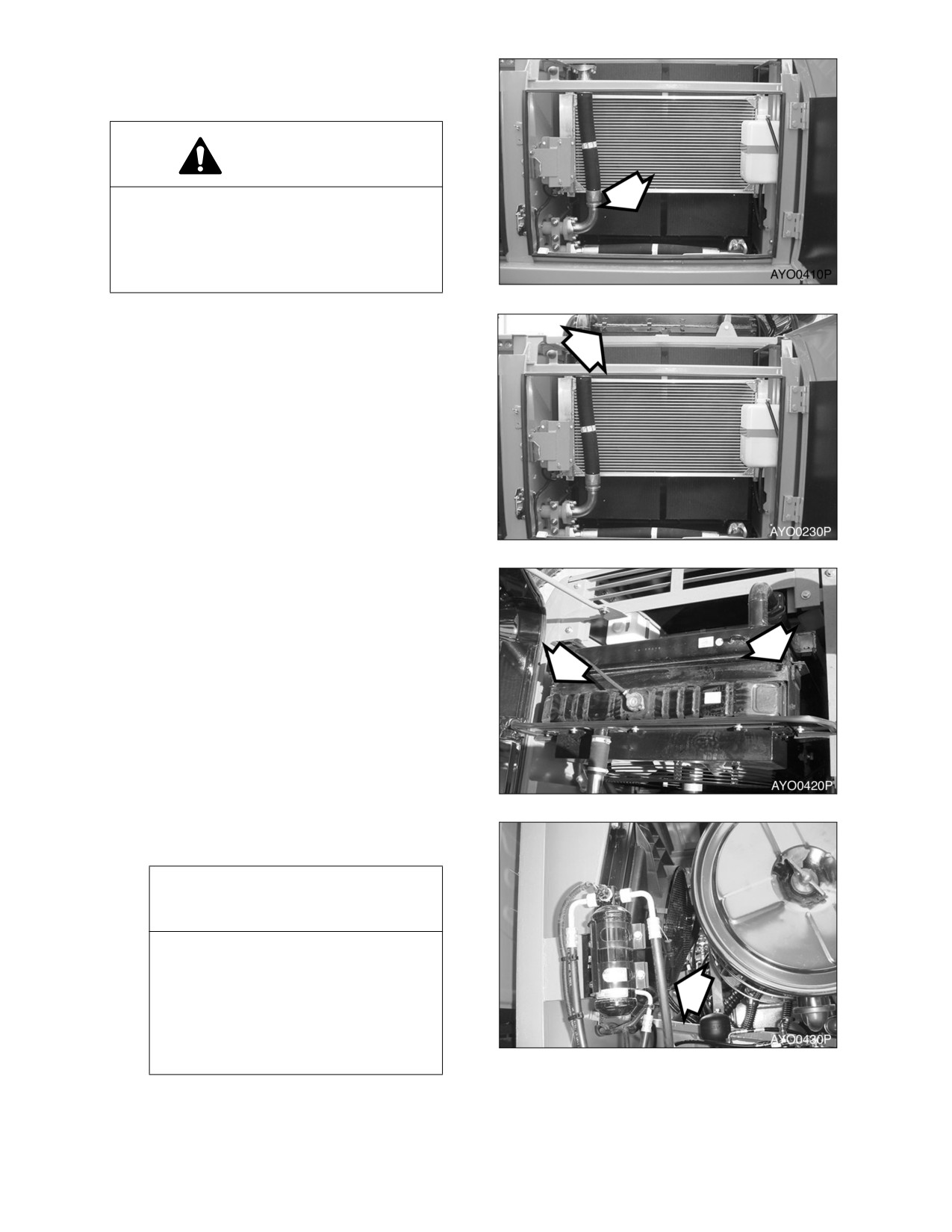
CLEAN RADIATOR, OIL COOLER,
INTERCOOLER AND AIR
CONDITIONER CONDENSER CORE
WARNING!
If compressed air, steam or water hit your
body directly, there is danger of injury.
Always wear protective glasses, mask and
safety shoes. Make sure that all extra
personnel are clear of the work area.
Figure 58
1.
Make sure to wear all appropriate safety
apparel
(mask safety glasses, safety
shoes, etc.) during the cleaning process.
2.
Loosen the wing nut(s) and remove dust
net from in front of oil cooler.
Figure 59
3.
Remove wing nuts and plate (Figure 60)
between radiator and oil cooler.
4.
Clean the outside of the radiator and oil
cooler and intercooler with compressed
air, steam or water. Wash from the outside
of the engine compartment inwards.
Repeat the cleaning process from the
inside of the engine compartment
outwards to remove all dirt and debris.
NOTE: Clean dust net and install it
after cleaning radiator, oil cooler
and intercooler.
Figure 60
5.
Clean air conditioner condenser core with
compressed air, steam or water.
IMPORTANT
To prevent damage to the cores,
apply compressed air from an
appropriated distance. Damaged
core may cause water leakage or
overheating. In a dusty site, check
the core daily, irrespective of the
maintenance interval.
Figure 61
022-00031E Operation and Maintenance Manual
Inspection, Maintenance and Adjustment 4-35
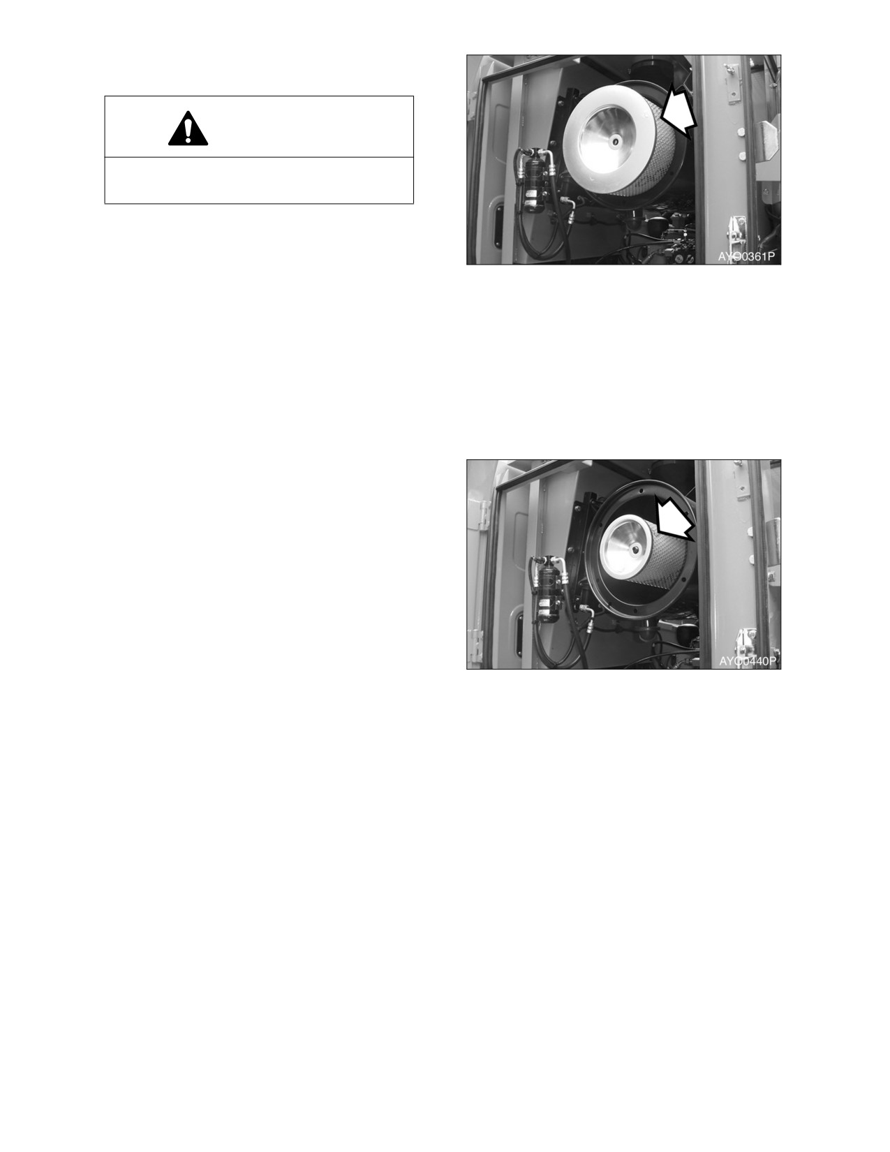
REPLACE OUTER AND INNER AIR
CLEANER ELEMENTS
WARNING!
Never clean or attempt to remove the air
cleaner element if the engine is running.
NOTE: Replace
inner
element
whenever a new outer element
is installed.
Figure 62
1.
Open the access door at the rear of the
cabin,
2.
Remove the wing nut and air cleaner
cover.
3.
Remove the wing nut and outer element
from the air cleaner housing.
4.
Clean the air cleaner cover and the inside
of the air cleaner housing.
5.
Remove wing nut and inner element.
6.
Clean out inside of air cleaner housing.
DO NOT use compressed air to blow out
housing.
7.
Install new inner element, and secure it
into position with wing nut. DO NOT clean
and re-use inner element.
8.
Install new outer element, and secure it
into position with wing nut.
9.
Install air cleaner cover.
NOTE: Make sure that all gaskets on
Figure 63
wing nuts and cover are
properly installed and seated.
4-36 Inspection, Maintenance and Adjustment
022-00031E Operation and Maintenance Manual
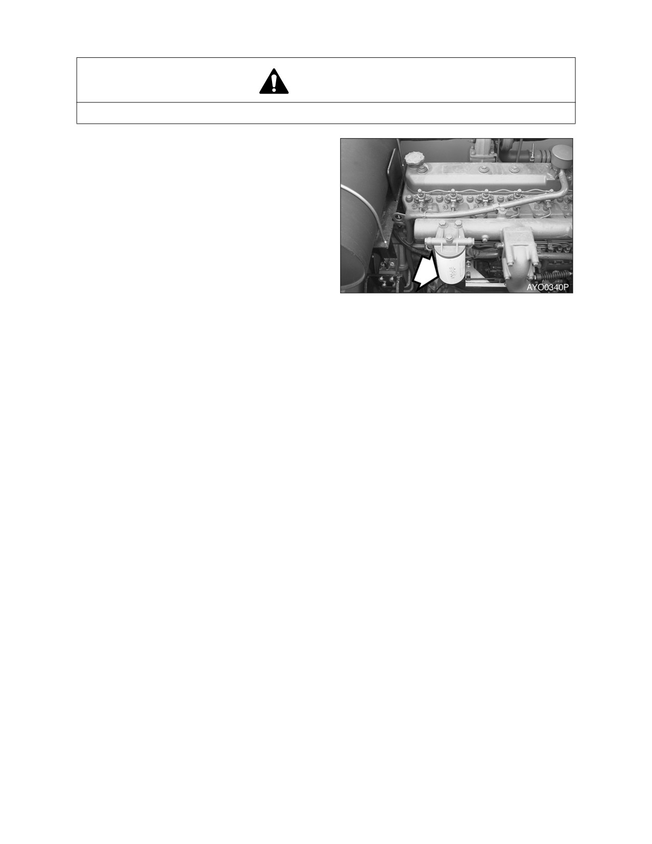
CHANGE FUEL FILTER
WARNING!
Exchange filter after waiting for engine to cool. Be careful of fire hazards. Do not smoke.
1.
Locate fuel
filter
inside
engine
compartment.
2.
Position a small container under fuel filter.
Drain fuel by opening drain valve on
bottom of filter.
NOTE: Dispose of drained fluids
according to local regulation.
3.
Unscrew fuel filter from head assembly.
Discard fuel filter.
4.
After cleaning filter head, install new fuel
filter. Screw filter on head until gasket
Figure 64
contacts head, turn filter
1/3
-
1/2 turn
more.
NOTE: Coat fuel filter gasket with fuel.
NOTE: Fill fuel filter with clean fuel.
This will help reduce fuel
system priming.
5.
Start engine. After engine has run for a
couple of minutes, shut down engine and
look for leaks.
022-00031E Operation and Maintenance Manual
Inspection, Maintenance and Adjustment 4-37
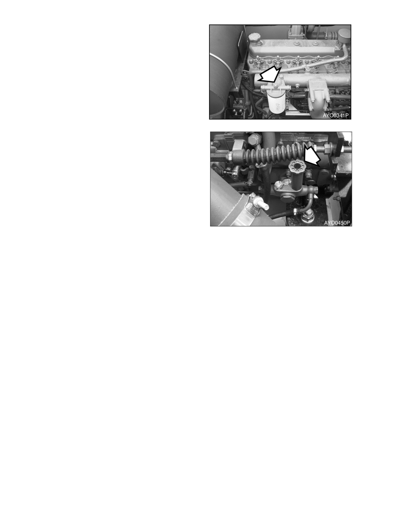
Prime the Fuel System
If engine does not start, the fuel system may
need priming. Prime the fuel system using the
following procedure;
1.
Loosen plug (Figure 65) on top of fuel filter
head.
Figure 65
2.
Unscrew and pump the hand operated
primer pump
(Figure
66) by the fuel
injection pump. Pump primer until fuel is
present at plug hole in fuel filter head.
3.
Tighten plug in fuel filter head.
4.
Continue to pump primer pump until a
strong resistance is felt. Screw the primer
pump knob back into housing.
5.
Start engine and look for signs of leaks.
6.
Repeat procedure if necessary.
Figure 66
4-38 Inspection, Maintenance and Adjustment
022-00031E Operation and Maintenance Manual
1000 HOUR / 6 MONTH SERVICE
PERFORM ALL DAILY (10 HOUR), 50, 250 AND 500 OPERATING HOUR SERVICE CHECKS
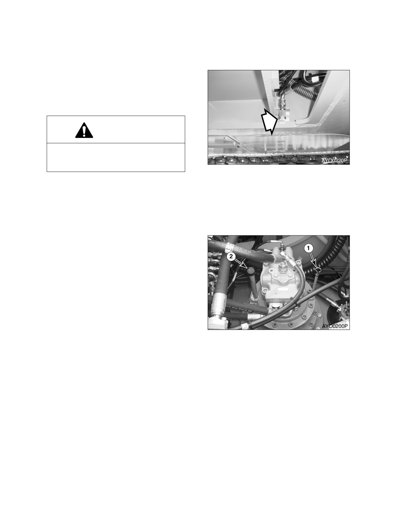
CHANGE SWING REDUCTION DEVICE OIL
NOTE: Change swing reduction device
oil after first 250 hours on a new
machine and every 1000 hours
thereafter.
WARNING!
The gear oil is very hot after the machine
has been operating. Shut all systems
down and allow them to cool.
Figure 67
1.
Set a container under excavator.
2.
Open drain plug (Figure 67).
NOTE: Dispose of drained fluids
according to local regulation.
3.
After draining oil close drain plug.
4.
Remove breather/fill cap (2, Figure 68) and
add oil to "H" mark on dipstick (1, Figure
68)
Figure 68
022-00031E Operation and Maintenance Manual
Inspection, Maintenance and Adjustment 4-39
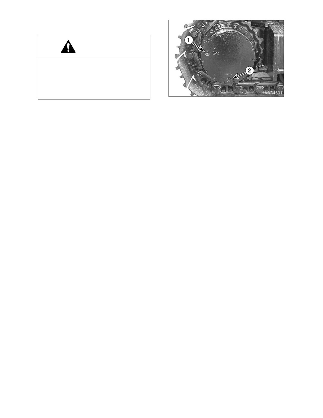
CHANGE OIL IN TRAVEL REDUCTION
DEVICE (ONE ON EACH SIDE OF UNIT)
WARNING!
The gear oil is very hot after the machine
has been operating. Shut all systems
down and allow them to cool. Before fully
removing any motor case, inspection port
plug, etc., loosen the plug slightly to allow
pressurized air to escape.
Figure 69
NOTE: Drain oil after first 250 hours of
operation and every 1000 hours
thereafter.
1.
Make sure that the machine is on a firm,
level work area.
2.
Rotate the track until ports (1 and 2, Figure
69) are in their proper positions as shown.
3.
Place a container under drain plug
(2,
Figure 69) and remove plugs (1 and 2) to
drain the travel motor fluid.
NOTE: Dispose of drained fluids
according to local regulation.
4.
Install drain plug (2, Figure 69). Refill the
travel motor case with fluid through level
port (1) until the fluid level is at port (1).
Install level plug (1).
NOTE: See
“Fluid Capacities” on
page 4-7. for capacity.
5.
Repeat this procedure on the other travel
motor.
4-40 Inspection, Maintenance and Adjustment
022-00031E Operation and Maintenance Manual
CHANGE RADIATOR COOLANT
WARNING!
1.
Allow the engine to cool before
releasing the radiator cap. Make sure
to loosen the cap slowly to release
any remaining pressure.
2.
Radiator cleaning is performed while
the engine is running. Take extreme
caution when working on or near a
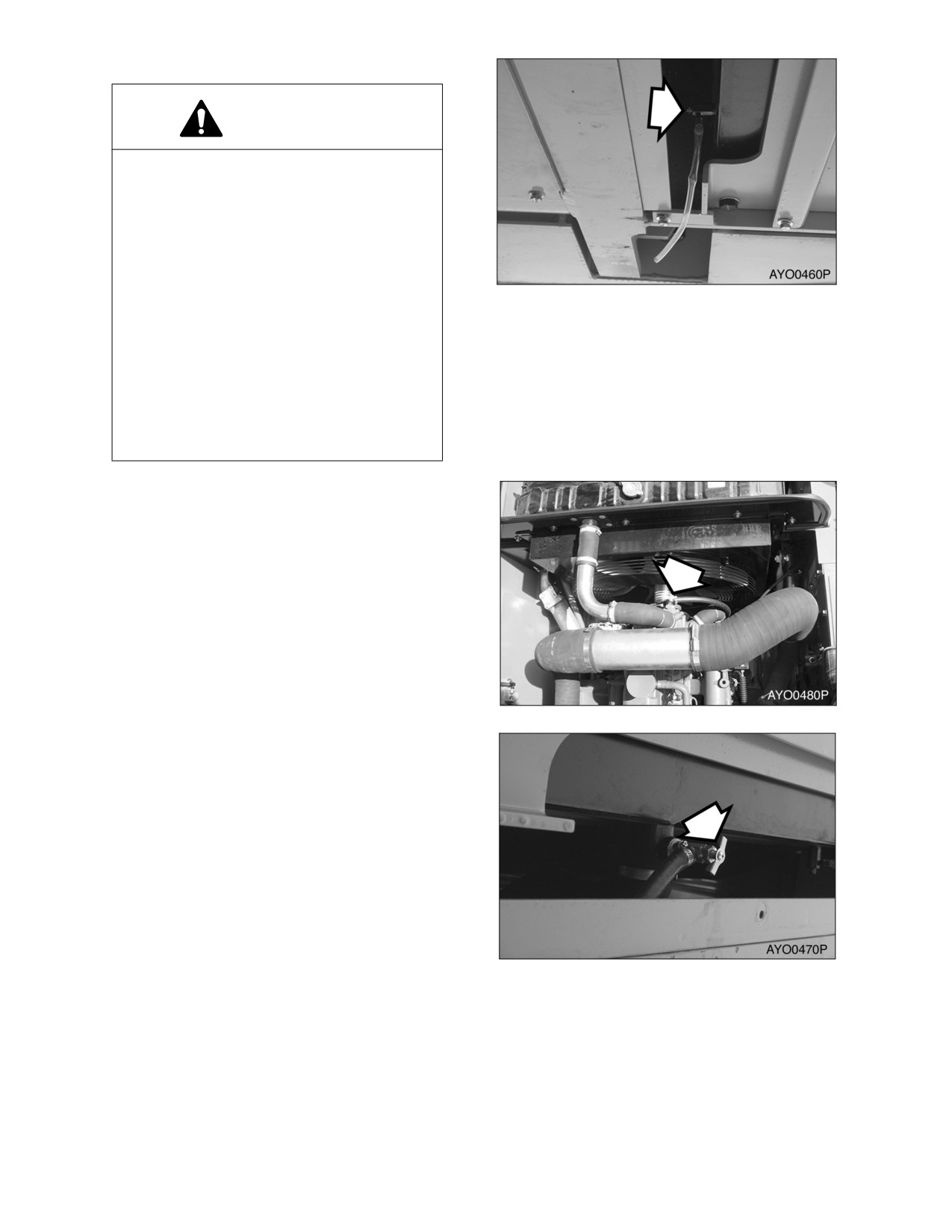
Figure 70
running engine. Make sure to lock
out and tag the controls notifying
personnel that service work is being
performed.
3.
Do not remove the radiator cap
unless it is required. Observe the
coolant level in the coolant recovery
tank.
1.
Slowly open the radiator cap to allow any
pressure to escape.
2.
Place a container under the radiator and
open the drain valve (Figure 70).
NOTE: Dispose of drained fluids
according to local regulation.
3.
Open heater shut-off valves (Figure 71 and
Figure 72) to allow coolant to drain from
heater core.
Figure 71
Figure 72
022-00031E Operation and Maintenance Manual
Inspection, Maintenance and Adjustment 4-41
4.
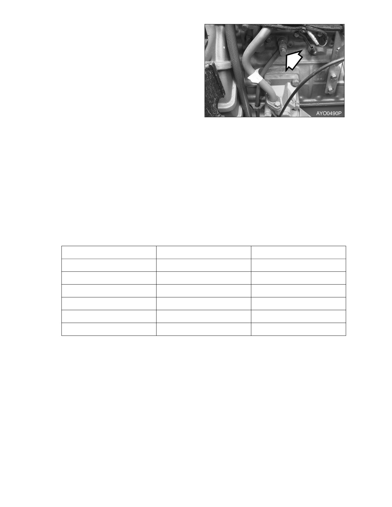
Remove coolant drain plug (1, Figure 73)
from engine.
5.
Install drain plug, and close drain valve
after coolant has completely drained from
system.
6.
Fill cooling system with a flushing solution.
7.
Run engine at low idle until the coolant
temperature gauge reaches the "GREEN
ZONE." Run engine for another
10
minutes.
8.
After allowing engine to cool.
Figure 73
9.
Drain flushing fluid and fill system with
water.
10.
Run engine again to allow water to
completely circulate.
11.
Drain water and fill system with proper
anti-freeze
mixture
for
ambient
temperature.
Refer
to
coolant
concentration table. (See page 4-42)
12.
Run engine without radiator cap installed,
so that all air will be purged from system.
Fill radiator to fill neck.
13.
Drain and fill radiator coolant recovery
tank.
AMBIENT TEMPERATURE
COOLING WATER
ANTIFREEZE
-10°C (15°F)
80%
20%
-15°C (5°F)
73%
27%
-20°C (-5°F)
67%
33%
-25°C (-15°F)
60%
40%
-30°C (-20°F)
56%
44%
-40°C (-30°F)
50%
50%
4-42 Inspection, Maintenance and Adjustment
022-00031E Operation and Maintenance Manual
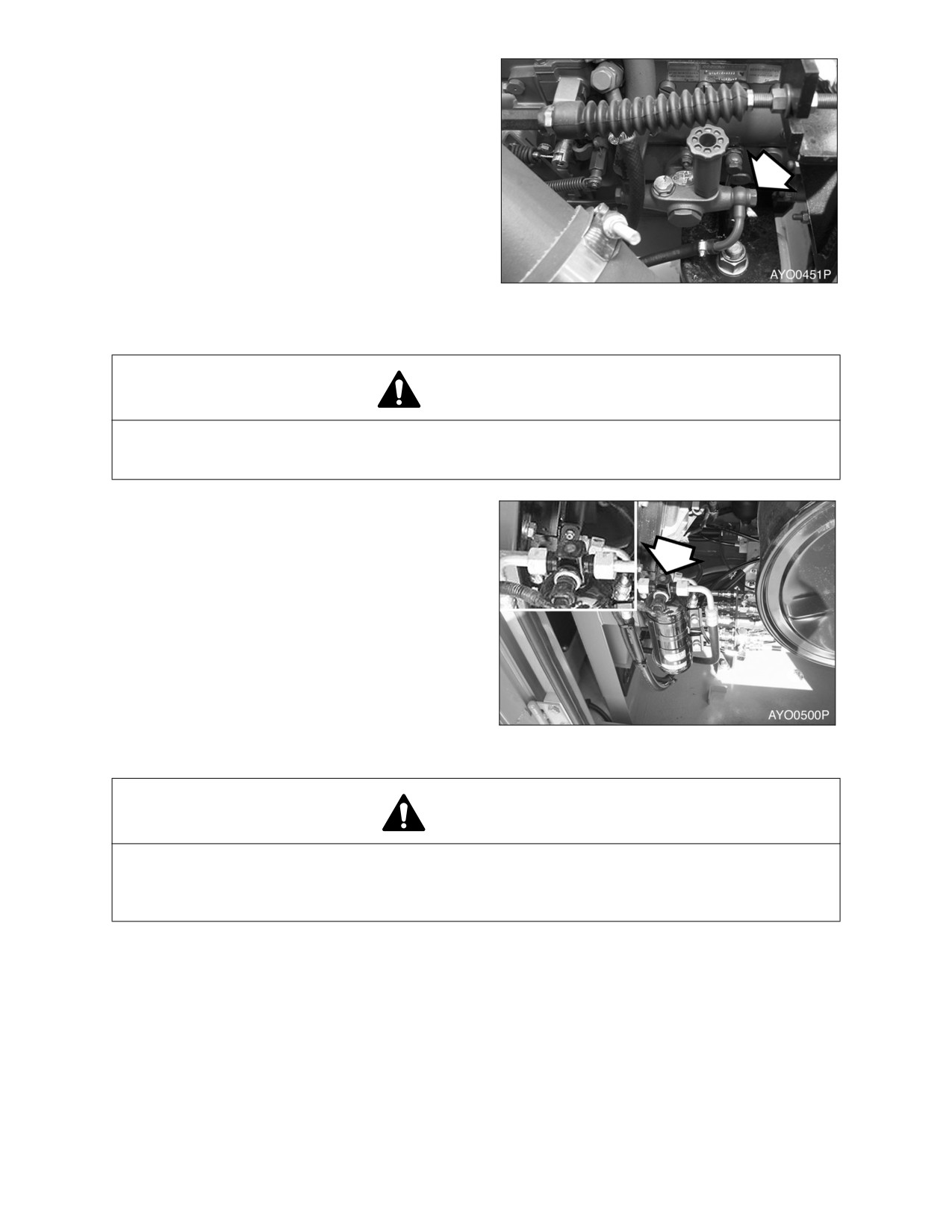
CLEAN FUEL INJECTION PRIMING PUMP
STRAINER
1.
Remove fitting, fuel line and strainer from
side of priming pump.
2.
Clean strainer.
3.
Position strainer in priming pump and
install fuel line and fitting.
Figure 74
CHECK AIR CONDITIONER REFRIGERANT
WARNING!
Mixing of tobacco smoke and freon is deadly.
Do not smoke while servicing or recharging air conditioning system.
1.
Run engine about 1800 rpm. Operate for a
minimum of ten minutes to stabilize the
system.
2.
Press the "HI" fan speed switch to set
maximum air flow.
3.
Put the temperature control switch in
maximum cool position.
4.
Press the "Internal Air Circulation" switch.
5.
Compare the flow of bubbles in the sight
glass of receiver dryer with the drawings in
the following table.
Figure 75
CAUTION!
Overfilling refrigerant may cause dangerous high pressure and poor cooling action; and low
refrigerant level may cause compressor damage.
Always maintain refrigerant at normal level.
022-00031E Operation and Maintenance Manual
Inspection, Maintenance and Adjustment 4-43
Amount of
Appearance of the Sight Glass
Solutions
Refrigerant
Almost clear.
Normal
Any bubbles disappear.
Charge or with draw the system
with the correct amount of HFC-
High
No bubble is seen.
134a refrigerant.
Low
A flow of bubbles is visible.
CHECK AND ADJUST ENGINE **
Contact your nearest Daewoo excavator dealer.
Engine dealer for checking and adjusting the following items:
•
Engine Compression Pressure.
•
Injection Pressure.
•
Injection Timing.
4-44 Inspection, Maintenance and Adjustment
022-00031E Operation and Maintenance Manual
2000 HOUR / YEARLY SERVICE
PERFORM ALL DAILY, 50, 250, 500 AND 1,000 OPERATING HOUR SERVICE CHECKS
CHECK ALTERNATOR AND STARTER**
**These checks need to be completed by an authorized Daewoo dealer.
CHECK ALL RUBBER ANTI-VIBRATION SHOCK MOUNTS
PERFORM AND RECORD THE RESULTS OF THE CYCLE TIME TESTS
INSPECT MACHINE TO CHECK FOR CRACKED OR BROKEN WELDS OR OTHER STRUCTURAL
DAMAGE
CHECK, ADJUST VALVE CLEARANCE **
CHECK HEAD BOLT TORQUES
HYDRAULIC OIL EXCHANGE AND SUCTION
STRAINER CLEANING
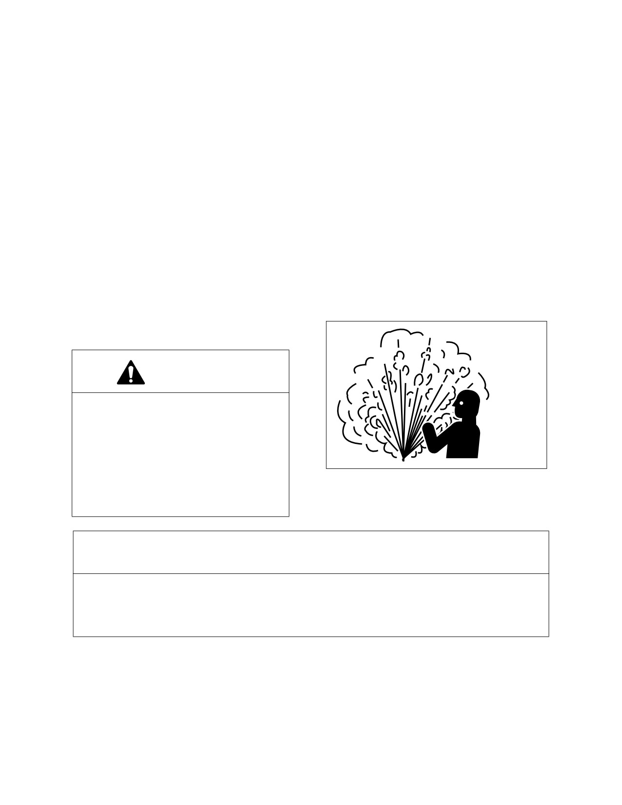
WARNING!
The hydraulic oil will be hot after normal
machine operation. Allow the system to
cool before attempting to service any of
the hydraulic components.
The hydraulic tank is pressurized. Loosen
ARO1760L
the air breather cap to allow the
Figure 76
pressurized air to vent. After the pressure
has been released, it is safe to remove
either the fill cap or service covers.
IMPORTANT
Make sure to clean any dirt or water from the top of the hydraulic tank, especially around the fill
port and filter ports.
Hydraulic oil change interval is 2,000 hours, only when Daewoo Genuine Oil is used. If other
brands of oil is used, guaranteed change interval is 1,000 hours.
NOTE: Based on the type of excavating being completed, the working conditions (extremely hot or
dusty) and the extra front end attachments being used (hydraulic breaker, etc.), the
hydraulic fluid will need to be changed more frequently.
022-00031E Operation and Maintenance Manual
Inspection, Maintenance and Adjustment 4-45
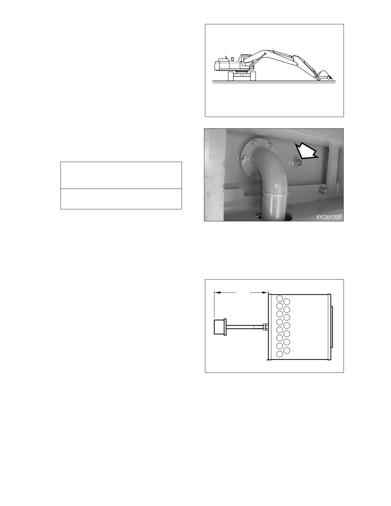
1.
Position the machine on firm, level ground.
Swing upper structure perpendicular (90°)
to tracks. Lower boom and position bucket
on ground as shown in Figure 77.
2.
Set safety lever on "LOCK" position.
3.
Shut down engine.
4.
Release pressurized air from hydraulic
tank by rotating air-breather cap (1, Figure
80).
HAOC390L
Figure 77
5.
Drain hydraulic oil from tank into a
container capable of holding 290 liters (77
U.S. gal.). After draining tank install drain
plug.
IMPORTANT
Be careful of squirting oil when
removing drain plug.
NOTE: Used filter and used oil should
always be disposed of
Figure 78
according to local regulations.
6.
Carefully remove bolts and cover
(2,
Figure 80) from top of hydraulic oil tank.
There is a spring (3) under the cover that
will force the cover up.
7.
Remove spring (3, Figure 80) and strainer
(5), by pulling on rod (4).
A
8.
Clean inside and outside of strainer.
Replace strainer if it is broken.
9.
Position strainer
(5, Figure
80) on boss
portion of suction pipe (6).
NOTE: Measurement "A" is 655 mm
(25.79 in).
HAOC411L
Figure 79
4-46 Inspection, Maintenance and Adjustment
022-00031E Operation and Maintenance Manual
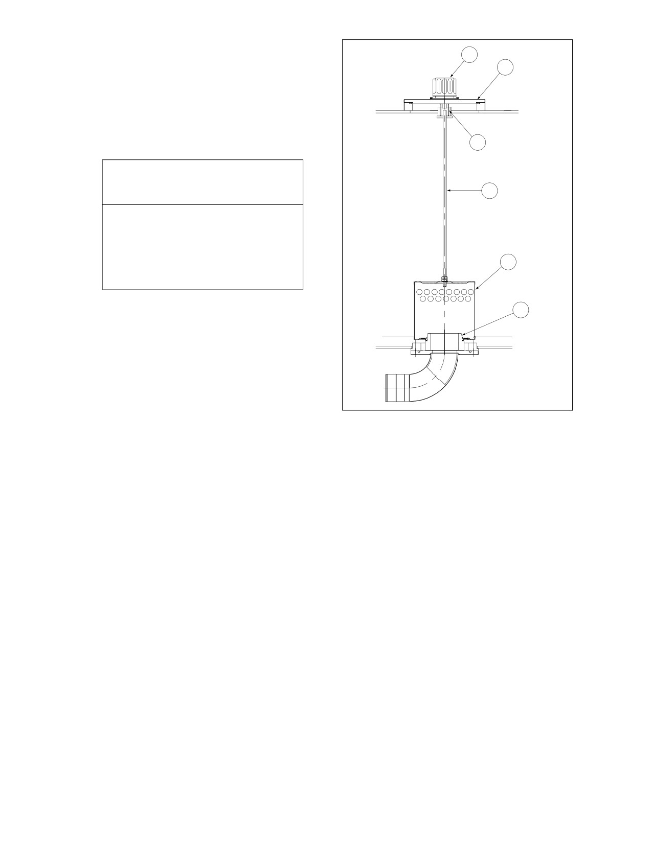
10. Fill the hydraulic oil tank. Check level using
sight gauge on side of tank.
1
2
11. Place spring (3, Figure 80) on rod (4) and
assemble cover (2).
12. After replacing and cleaning the hydraulic
oil, filter element and strainer, vent the
system. See
“Venting and Priming
Hydraulic System” on page 4-50.
3
IMPORTANT
4
When the hydraulic breaker is being
used, due to the higher heat
generated by this unit, use
replacement intervals recommended
5
under the “Hydraulic Oil and Filter
Service Intervals” on page 3-35.
13. Check level of hydraulic oil tank. (See page
6
4-13)
ARO1720L
Figure 80
022-00031E Operation and Maintenance Manual
Inspection, Maintenance and Adjustment 4-47
4000 HOUR / BIENNIAL SERVICE
MAJOR PARTS - PERIODIC REPLACEMENT
To ensure safe operation and work, perform periodic inspections. Also, to increase safety, replace the
following parts. These parts are the ones most often subjected to abrasion, heat and fatigue. Exchange
these parts with new ones at the designated time intervals, even if the old parts look good.
Always replace all related parts such as gaskets and O-rings. Use only original equipment manufacturers
parts.
MAJOR COMPONENT
PARTS NAME TO BE EXCHANGED
TIME TO EXCHANGE
PERIODICALLY
ENGINE
Fuel hose (Tank to water separator)
2 years or 4,000 hours
Fuel hose (Water separator to fuel injection pump)
Fuel hose (Tank to fuel injection pump)
Heater hose (Heater to engine)
Heater hose (Heater to radiator)
Air-conditioner hose
HYDRAULIC
BODY
Pump suction hose
SYSTEM
Pump discharge hoses
Pump side branch hoses
Swing motor hoses
Travel motor hoses
WORK
Boom cylinder line hoses
DEVICE
Arm cylinder line hoses
Bucket cylinder line hoses
4-48 Inspection, Maintenance and Adjustment
022-00031E Operation and Maintenance Manual
12,000 HOUR / SIX YEAR SERVICE
HOSE IN-SERVICE LIFETIME LIMIT (EUROPEAN STANDARD ISO 8331 AND EN982 CEN)
European regulations state that the in-service life of any hydraulic hose may not exceed six years. Daewoo
recommends the following;
•
Hoses at the customer premises can not be stored more than 2 years before being discarded or
installed on a machine.
•
In-service lifetime of hoses fitted on a machine can never exceed 6 years, but replace hoses
describe in “Major Parts - Periodic Replacement” on page 4-48, every 2 years. Always replace
hoses having exceeded the allowed in-service lifetime irrespective of the external appearance/
wear.
•
Always store hoses in a dark place at a maximum of 65% relative humidity, between 0°C (32°F)
and 35°C (95°F) but as close as possible to 15°C (59°F) and away from copper, manganese or
tube generating Ozone.
022-00031E Operation and Maintenance Manual
Inspection, Maintenance and Adjustment 4-49
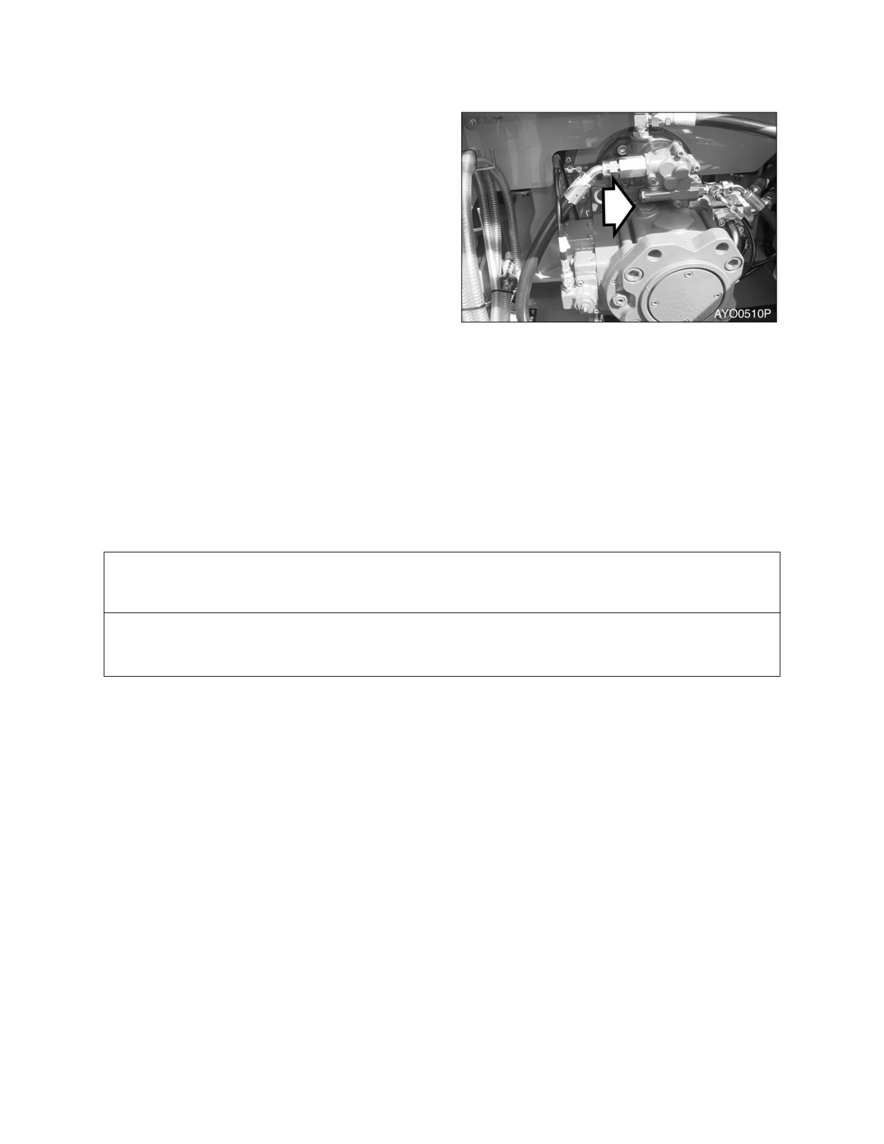
VENTING AND PRIMING HYDRAULIC SYSTEM
MAIN SYSTEM PUMP
NOTE: If pump is run without sufficient
oil in the main hydraulic pump,
damage can occur. Always vent
pump of air after draining
hydraulic system.
1.
With the engine stopped, remove vent plug
(Figure 81) to see if any oil is present.
2.
If oil is not present, fill pump with oil
through port (Figure 81).
3.
Install vent plug (Figure 81) first.
Figure 81
4.
Start engine and run it for several minutes
at low idle engine speed. This will
pressurize the hydraulic oil tank and
system.
5.
Slowly loosen vent plug (Figure 81) several
turns, until hydraulic oil flows out of plug.
This shows that air has been released.
6.
Tighten the plug (Figure 81).
HYDRAULIC CYLINDERS
IMPORTANT
If cylinders are operated in high idle after the hydraulic system has been drained or the cylinder
has been rebuilt, damage to piston packing and seals may occur. Always vent air from cylinders
at low idle and at a slow speed.
1.
Run engine at low idle. Extend and retract each cylinder to within 100 mm (4 in) of fully stroking it 4 -
5 times.
2.
Operate fully extend and retract each cylinder 3- 4 times.
3.
Repeat procedure until cylinders extend and retract smoothly.
4-50 Inspection, Maintenance and Adjustment
022-00031E Operation and Maintenance Manual
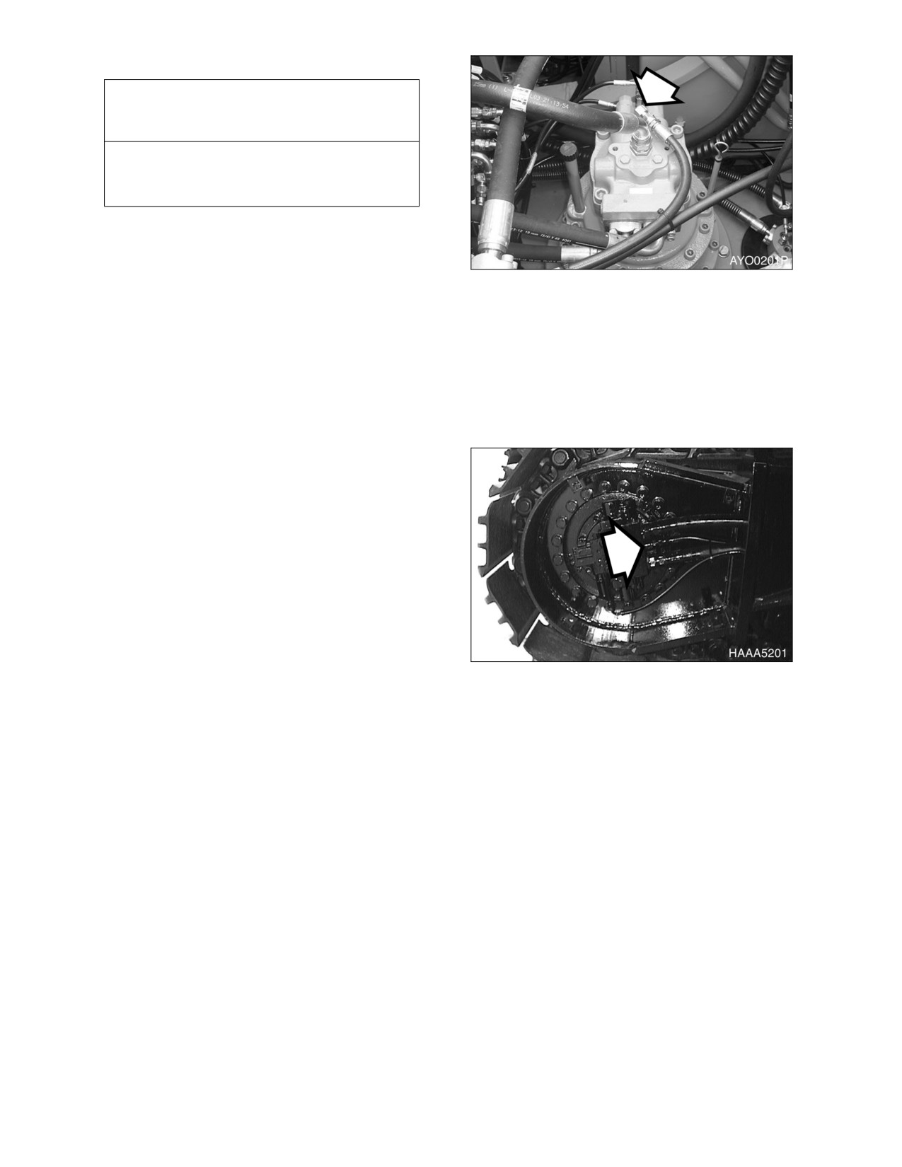
SWING MOTOR
IMPORTANT
If the air is not vented from the system, it
will cause damage to the swing motor and
bearings.
NOTE: Perform this only when oil has
been drained from swing motor.
1.
Shut down engine.
Figure 82
2.
Disconnect drain hose and fill swing motor
case with hydraulic oil.
3.
Connect the drain hose.
4.
Start engine and set throttle at "LOW
IDLE" and swing upper structure slowly
two full revolutions to the left and right.
AIR RELEASE OF TRAVEL MOTOR
NOTE: Perform this only when oil is
drained from travel motor
1.
Shut down engine.
2.
Disconnect drain hose (Figure 83) and fill
motor case with hydraulic oil.
3.
Connect drain hose.
4.
Start engine and set engine speed control
dial to "LOW IDLE." Run the engine for
one minute and slowly drive excavator
forwards and backwards.
Figure 83
GENERAL VENTING
1.
After venting air from all components, shut the engine down and check the hydraulic oil level. Fill
hydraulic oil tank to "H" mark on sight gauge.
2.
Start engine and operate all controls again, run engine for 5 minutes to ensure all system have been
vent and purged of air. Shut down engine and check hydraulic oil level again. Add oil as necessary.
3.
Check for oil leaks and clean all fill and venting locations.
022-00031E Operation and Maintenance Manual
Inspection, Maintenance and Adjustment 4-51
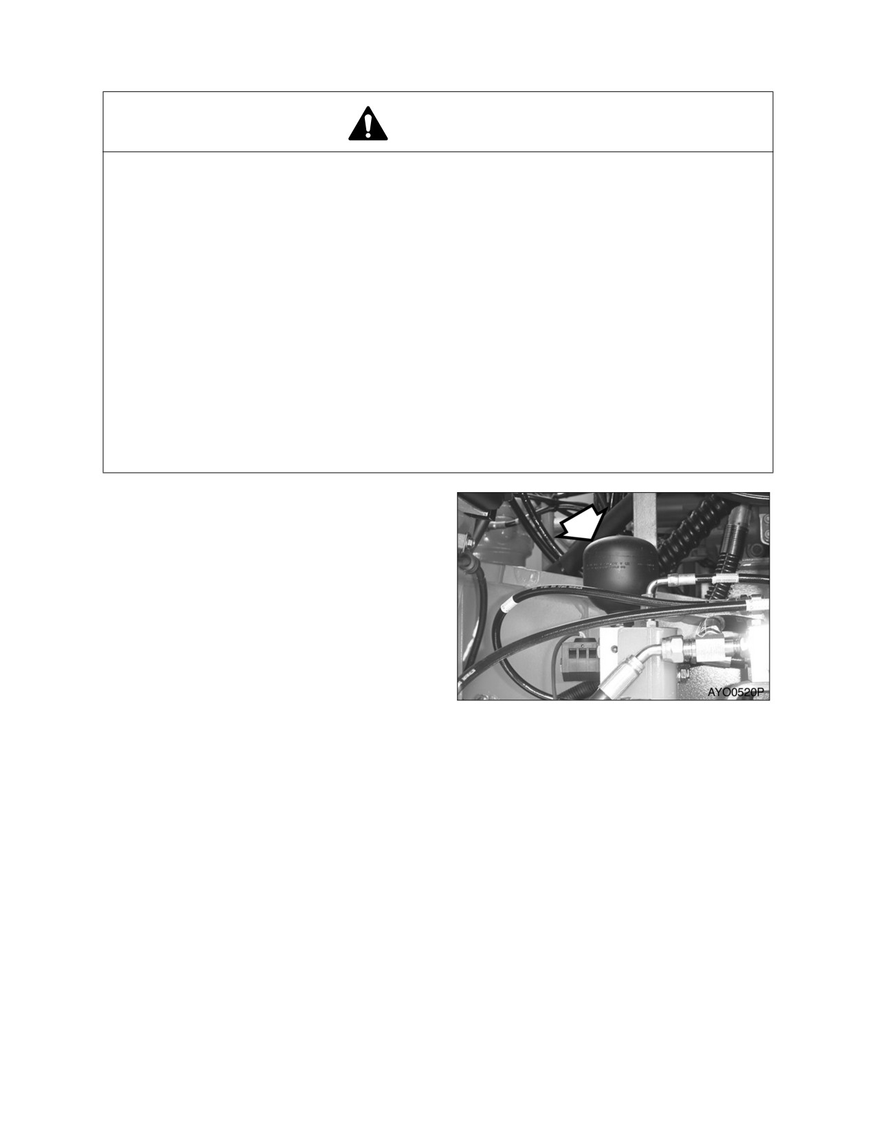
HANDLING OF ACCUMULATOR
WARNING!
Even though the engine is stopped, the hydraulic accumulators for the pilot system are still
charged. Do not disconnect any pilot system hoses until accumulator pressure has been
released from the circuit. To release pressure, turn the starter switch to “I” (ON) position and
operate all hydraulic control levers and forward/reverse travel levers. Even though the engine is
shut down, hydraulic actuated components may move while releasing pilot pressure. Keep all
personnel away from excavator while performing this operation.
•
Set safety lever on "LOCK" position after stopping engine.
•
DO NOT mishandle accumulator(s). They are very dangerous because they contain
high pressure nitrogen gas.
•
DO NOT punch a hole or apply heat or fire to an accumulator.
•
DO NOT weld on accumulator, or try attaching anything to it.
•
When replacing an accumulator, contact a DAEWOO distributor or sales agency so the
gas can be properly released.
•
Wear safety goggles and protective gloves when working on an accumulator.
Hydraulic oil under pressure can penetrate the skin and cause serious injuries.
Release pilot accumulator pressure using the
following procedure;
1.
Lower front attachment
(bucket) on the
ground.
2.
Shut down engine.
3.
Set safety lever on "RELEASED" position.
4.
Turn starter switch "ON."
5.
Fully stroke work and travel levers in all
directions.
6.
Set safety lever on "LOCK" position.
Figure 84
7.
Turn key to "OFF" position and remove
from starter switch.
8.
Remove accumulator by unscrewing it
slowly.
4-52 Inspection, Maintenance and Adjustment
022-00031E Operation and Maintenance Manual
FUEL TRANSFER PUMP (OPTION)
WARNING!
1.
Do not dry operate fuel pump for more than 15 seconds.
•
Cooling and lubrication of pump is achieved by fuel passing through pump. If pump is
dry operated, heat generated by moving parts will cause damage to pump rotors,
vanes and seals. To prevent unnecessary wear and/or damage to pump do not dry
operate fuel pump for more than 15 seconds.
2.
Do not operate pump for more than 15 minutes at a time.
•
Continuous usage of pump over recommended time interval will cause overheating of
motor and will result in causing motor damage.
3.
Do not use refueling pump for other types of fuel or fluids. (Use only for diesel fuel.)
•
Do not use refueling pump for other types of fuel which have a low flash point.
•
Do not use refueling pump for fuel contaminated with water or high humidity. Moisture
in pump mechanism can cause rust and can create pump failure.
4.
Always operate pump using strainer installed on inlet hose. This will prevent any foreign
materials from being introduced into pump. Always maintain pump and all of its
components in a clean condition.
•
If dirt or other foreign materials enter pump, it can become lodged between the rotor
and/or vanes and generate heat which can cause pump damage.
•
Do not remove strainer or use a strainer with larger mesh to increase flow of fuel.
5.
Be careful not to overfill or spill fuel.
6.
Make sure direction of check valve is in line with flow direction of fuel.
7.
If any pump parts or components become lost, damaged or inoperable, immediately
replace it with a new ones.
IMPORTANT
If there are any sign of leakage while operating transfer pump, inspect the following components
to prevent any fires or hazardous fuel spills.
•
Check all hoses leading to and from the transfer pump.
•
Check all hose clamps.
•
Check transfer pump inlet port.
The transfer pump is used to transfer fuel from a refueling source to the fuel tank. A check valve is installed
in the inlet hose to prevent fuel from flowing back from fuel tank to source. A strainer is installed in inlet
hose to prevent any foreign material from being introduced into transfer pump or fuel tank.
A thermal limiter, built into the motor, will automatically shut off power if motor is overheating to protect it
from damage.
022-00031E Operation and Maintenance Manual
Inspection, Maintenance and Adjustment 4-53
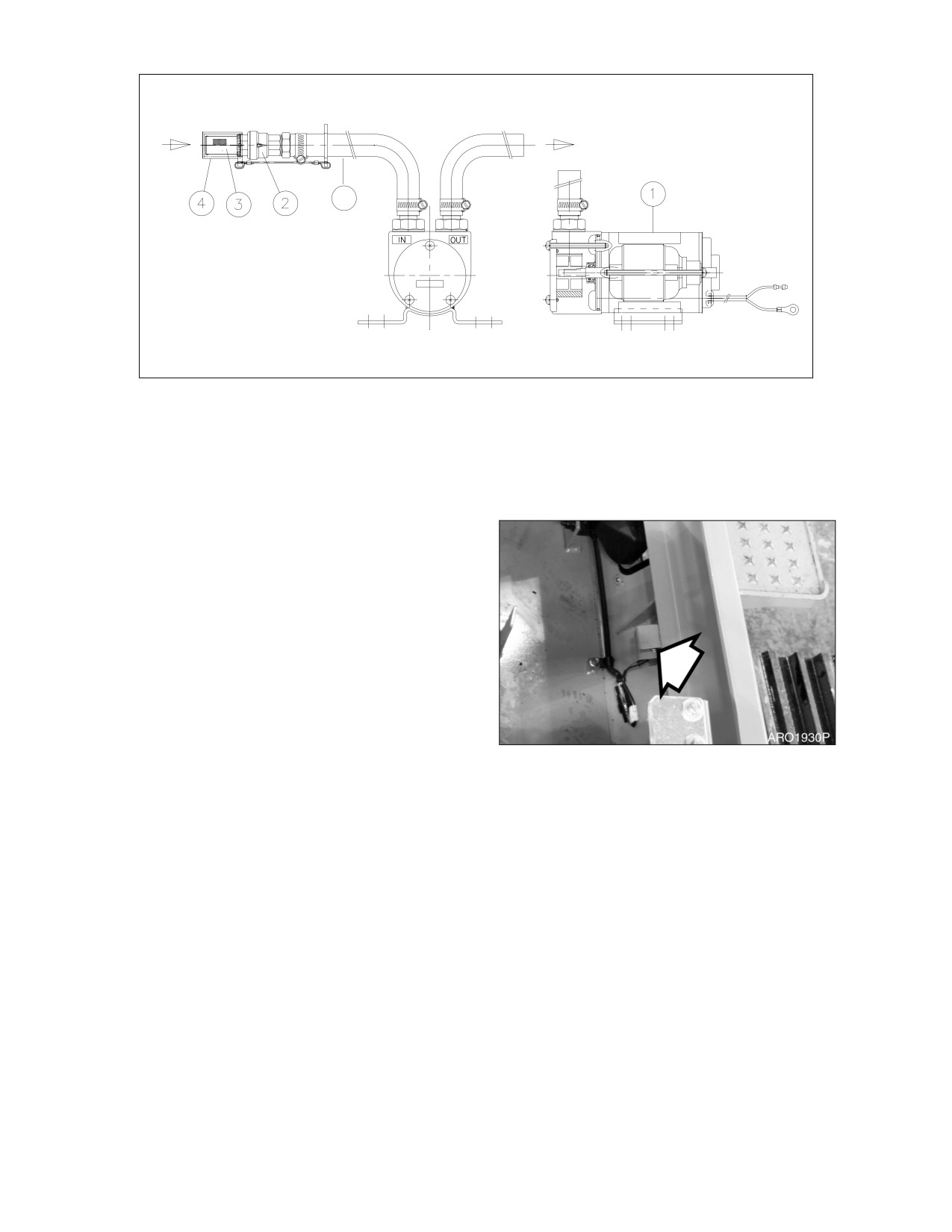
FUEL
FUEL TANK
5
HAOP551L
Figure 85
1.
BODY
4.
STRAINER CAP
2.
CHECK VALVE
5.
INLET HOSE
3.
STRAINER
1.
Remove strainer cap (4, Figure 85) from
strainer (3) on end of inlet hose (5).
NOTE: Keep strainer cap (4, Figure 85)
in a safe location to reseal
strainer
(3) after refueling is
complete.
2.
Insert inlet hose
(5, Figure
85) into
refueling tank.
3.
Turn fuel pump switch (Figure 86) inside of
battery box on front side to “ON” position.
NOTE: Transfer pump rate of flow is
Figure 86
approximately
35 liters/minute
(9.24 U.S. gpm). Use extra care
not to overfill fuel tank so that
fuel does not over flow.
4.
Once fuel transfer is completed,
immediately turn switch to “OFF” position
to stop pump.
5.
Lift inlet hose (5, Figure 85) from fueling
source and turn switch to “ON” position for
2 - 3 seconds to drain remaining fuel from
hose to fuel tank.
6.
Install strainer cap (4, Figure 85) on inlet
strainer (3) and return hose (5) to storage
position.
4-54 Inspection, Maintenance and Adjustment
022-00031E Operation and Maintenance Manual
ELECTRICAL SYSTEM
NOTE: Never disassemble electrical or electronic parts. Consult with a DAEWOO distributor or
sales agency before servicing.
BATTERY
WARNING!
Battery electrolyte contains sulfuric acid and can quickly burn the skin and eat holes in clothing.
If you spill acid on yourself, immediately flush the area with water.
Battery acid could cause blindness if splashed into the eyes. If acid into the eyes, flush them
immediately with large quantities of water and see a doctor at once.
If you accidentally drink acid, drink a large quantity of water or milk, beaten egg or vegetable oil.
Call a doctor or poison prevention center immediately.
When working with batteries, always wear safety glasses or goggles.
Battery generates hydrogen gas, so there is danger of explosion. Do not bring lighted cigarettes
near the battery, or do anything that will cause sparks.
Before working with batteries, shut down engine and turn the starter switch to the "OFF"
position.
Avoid short circuiting the battery terminals through accidental contact with metallic objects,
such as tool.
When removing or installing, check which is the positive (+) terminal and negative (-) terminal.
When removing the battery, first disconnect the negative (-) terminal. When installing the battery,
first connect the positive (+) terminal.
If the terminals are loose, there is danger that the defective contact may generate sparks that
will cause an explosion. When installing the terminals, install them tightly.
Batteries in Cold Weather
In colder weather a greater drain is placed on the batteries when they are used for the preheat cycle and
when starting a cold engine. Battery performance decreases as the temperature gets lower.
In extremely cold weather, remove the batteries at night and move them to a warm location. This will help
to keep them at a higher power level.
022-00031E Operation and Maintenance Manual
Inspection, Maintenance and Adjustment 4-55
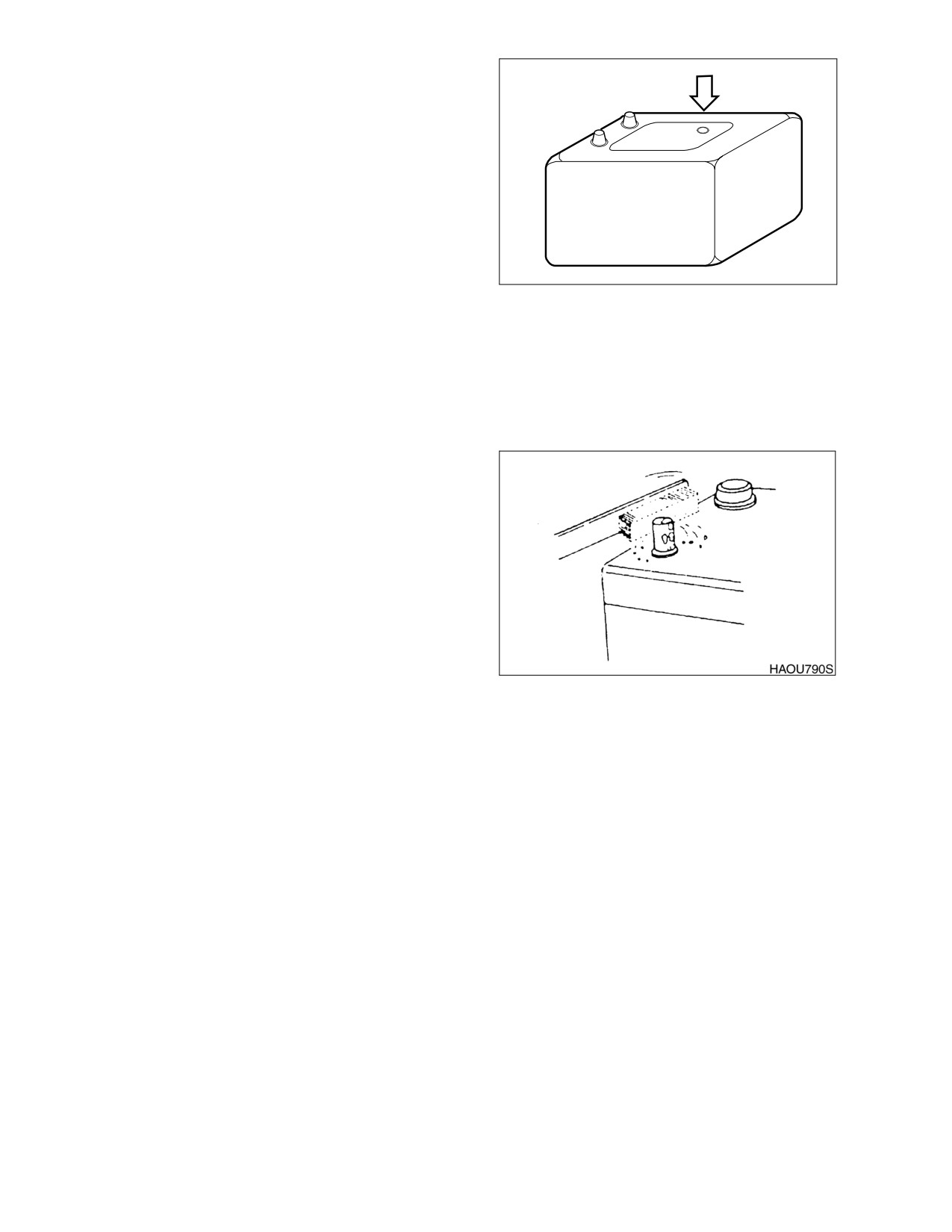
Inspection of Battery Electrolyte Level
This machine has two maintenance free
batteries. They never require the addition to
water.
When the charge indicator becomes
transparency, it means low electrolyte state
because of the leakage or charging system
error. Determine the cause of problem and
replace the batteries immediately.
Check Charging State
HAOC660L
Figure 87
Check charging state through the charging
indicator.
•
GREEN: Sufficiently charged.
•
BLACK: Insufficient charged.
•
TRANSPARENT: Replace battery.
Check the Battery Terminals
Be certain that the battery is held securely in its
compartment. Clean the battery terminals and
the battery cable connectors. A solution of
baking soda and water will neutralize acid on the
battery
surface,
terminals,
and cable
connectors. Petroleum jelly or grease can be
applied to the connectors to help prevent
corrosion.
Battery Replacement
When the charging indicator indicates
Figure 88
transparency state, replace the battery. The
batteries should always be replaced in pairs.
Using an old battery with a new one will shorten
the life span of the new battery.
4-56 Inspection, Maintenance and Adjustment
022-00031E Operation and Maintenance Manual
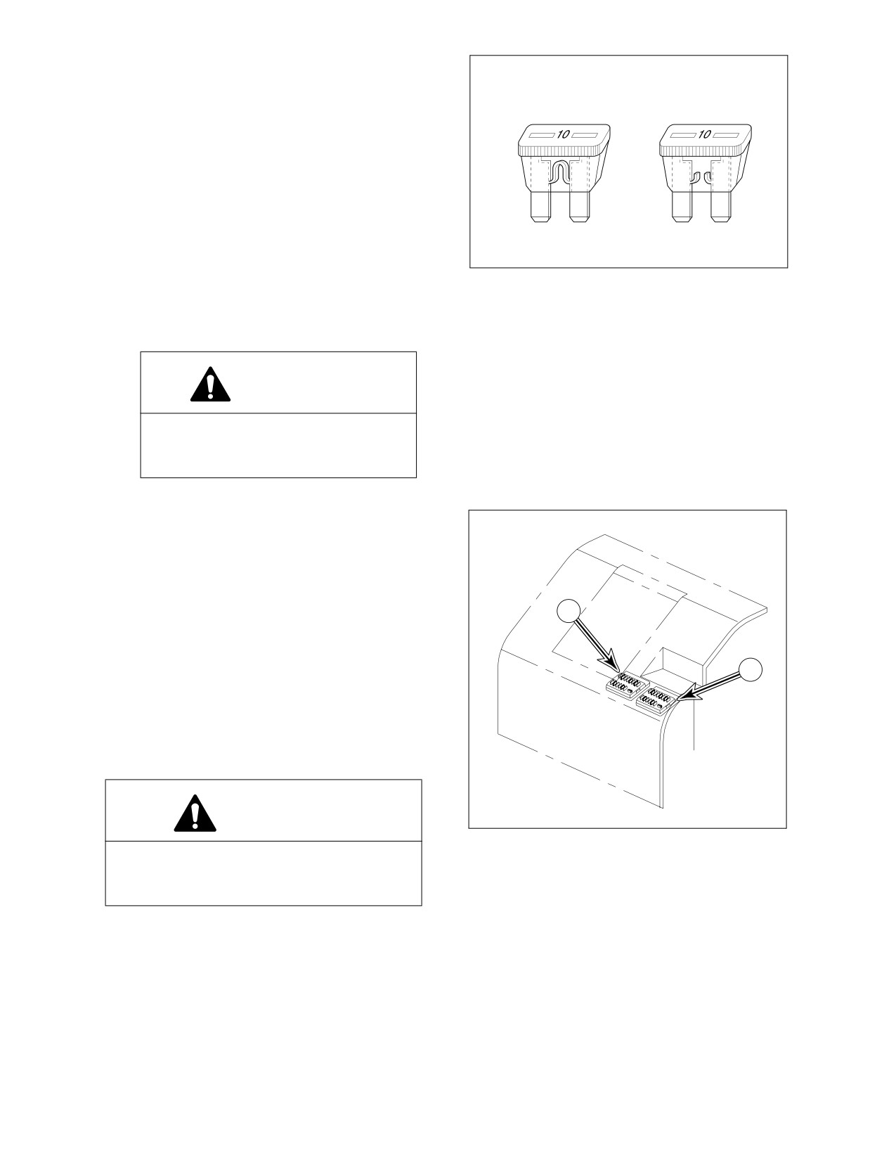
FUSES
1.
The fuses in the fuse box are used to
protect the various electrical circuits and
O
X
their components from damage. See
Figure 89. The fuses used are standard
automotive type fuses.
2.
The section on
“Fuse Identification” on
page 4-58, lists the circuits and the fuse
amperage required for each circuit. If a
fuse blows, determine the cause and
repair any faults or failures.
HAOC670L
3.
DO NOT insert a higher amperage fuse
Figure 89
into a lower amperage slot. Serious
damage to the electrical components or
fire can result.
CAUTION!
Before replacing a fuse, be sure to
turn starter switch to "O"
(OFF)
position.
Fuse Boxes
There are two fuse boxes (1 and 2, Figure 90)
on the left side of the heater box. The fuses
prevent electrical devices from overloading or
shorting.
1
A decal attached to the inside of the fuse box's
cover indicates the function and amperage of
each fuse.
2
Spare fuses are mounted on the inside of fuse
box's cover.
Change a fuse if the element separates. If the
element of a new fuse separates, check the
circuit and repair the circuit.
CAUTION!
ARO0620L
Figure 90
Always replace fuses with the same type
and capacity fuse that was removed.
Otherwise, electrical damage could result.
022-00031E Operation and Maintenance Manual
Inspection, Maintenance and Adjustment 4-57
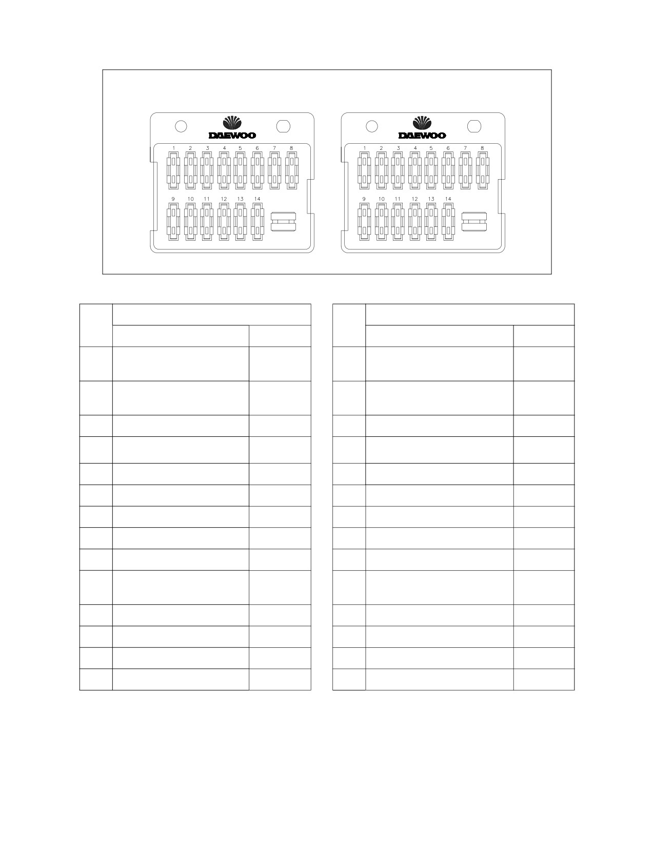
Fuse Identification
Fuse Box (1)
Fuse Box (2)
ARO1340L
Figure 91
Fuse Box One
Fuse Box Two
No.
No.
Name
Capacity
Name
Capacity
1
1
Breaker,
Horn
10A
10A
2-Way Valve (Option)
2
Instrument Panel,
2
10A
12V Power
10A
Pressure Sensor
3
Beacon Light (Option)
10A
3
Engine Speed Control
10A
4
4
Window Washer
10A
Travel Swing Alarm (Option)
10A
5
Wiper
10A
5
Spare
10A
6
Pilot Cut-off
10A
6
Spare
10A
7
Engine Stop
10A
7
Memory Backup
10A
8
Starter Switch
10A
8
Room Light, Hour Meter
10A
9
Air-conditioner, Heater
30A
9
Cabin Light (Option)
30A
10
e-EPOS, Booster,
10
20A
Work Light
20A
Travel Speed Change
11
Spare
15A
11
Headlight
15A
12
Spare
15A
12
Cigar Lighter
15A
13
Spare
15A
13
Spare
15A
14
Stereo
15A
14
Fuel Pump (Option)
15A
4-58 Inspection, Maintenance and Adjustment
022-00031E Operation and Maintenance Manual
AIR CONDITIONING SYSTEM
NOTE: See “Clean Air Conditioning Filter” on page 4-34.
CHECK CONTROL PANEL
When a switch is turned "ON," the pilot LED of pressed switch should light up and buzzer should sound.
When the light switch is turned "ON," the LED display should light up.
CHECK AIR CONDITIONER HOSES
Check the hose for cracking and damage.
CAUTION!
When a leak occurs, dirt will accumulate in the area where the leak is. Consult a DAEWOO
distributor or sales agency.
CHECK CONDENSER
Inspect the condenser for dust and debris. Clean if necessary.
NOTE: See “Clean Radiator, Oil Cooler, Intercooler and Air Conditioner Condenser Core” on
page 4-35.
CHECK MAGNETIC CLUTCH
Check the magnet clutch for dirt and interference.
Turn the starter switch to "I" (ON) position and check the magnet clutch for operation. If a fan speed is not
selected, the magnet clutch will not operate.
CHECK BELT TENSION
NOTE: See “Check Engine Fan Belt Tension” on page 4-27.
022-00031E Operation and Maintenance Manual
Inspection, Maintenance and Adjustment 4-59
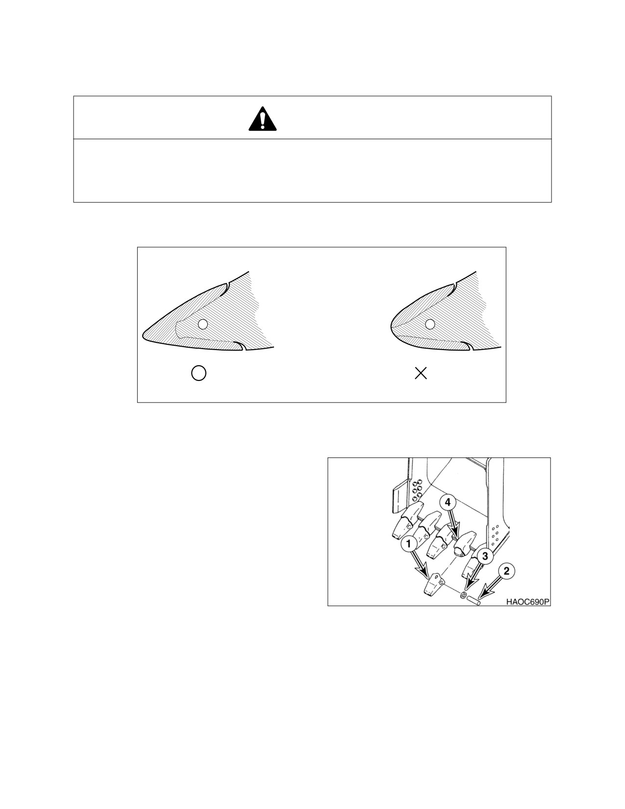
BUCKET
BUCKET TOOTH REPLACEMENT
WARNING!
Due to the possibility of flying metal objects, always wear safety helmet, protective gloves and
eye protection when changing bucket teeth.
Curl the bucket upwards and place the round rear surface of the bucket firmly on the ground.
Shut the engine off and lock out the hydraulic controls before working on the bucket.
NOTE: These instructions are only for Daewoo OEM buckets. If you are using other
manufacturers buckets, refer to their specific instructions.
HAOC680L
Figure 92
1.
On a routine basis, inspect bucket teeth to
make sure that tooth wear or breakage has
not developed. Do not allow replaceable
bucket teeth to wear down to a point that
bucket adapter is exposed. See Figure 92.
2.
To replace a tooth (1, Figure 93), use a
hammer and punch to drive locking pin (2)
and lock washer (3) out of tooth adapter
(4).
3.
Once worn tooth has been removed, use a
putty knife to scrape adapter as clean as
possible.
Figure 93
4.
Slide new tooth into position and insert
lock washer.
5.
Insert locking pin into tooth and with a
hammer, drive pin in until lock washer
seats in locking groove.
4-60 Inspection, Maintenance and Adjustment
022-00031E Operation and Maintenance Manual
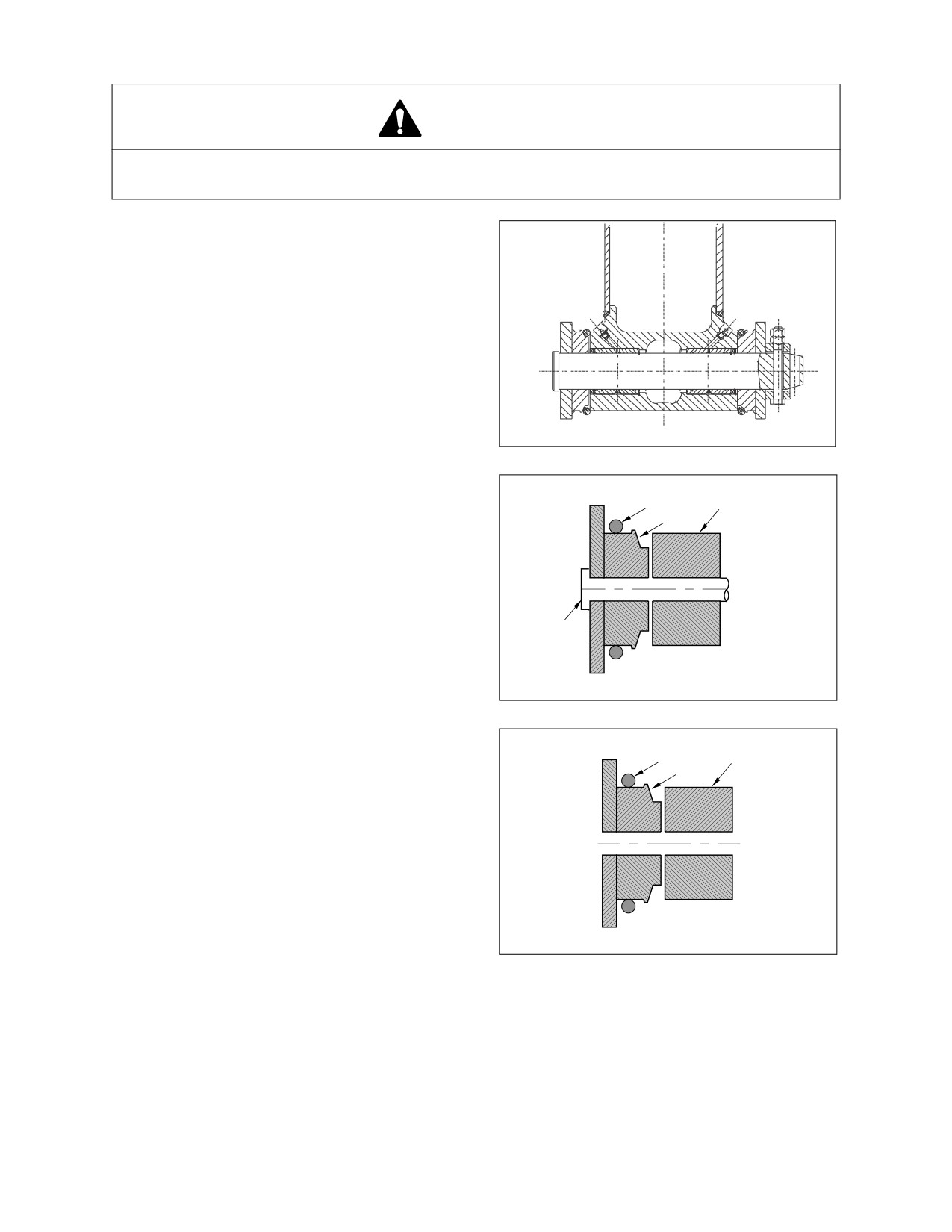
BUCKET O-RING REPLACEMENT
WARNING!
Due to possibility of flying metal objects, always wear safety helmet, protective gloves and eye
protection when changing pins.
1.
Inspect bucket O-rings on a routine basis.
If worn or damaged, replacement is
necessary.
HAOH640I
Figure 94
2.
Roll old O-ring (1, Figure 95) onto boss (2)
around bucket pin (3). Remove bucket pin
1
4
and move arm or bucket link (4) out of way.
2
3
HAOC710L
Figure 95
3.
Remove old O-ring and temporarily install
new O-ring (1, Figure 96) onto bucket boss
4
1
(2). Make sure that O-ring groove on both
2
bucket link
(4) and boss have been
cleaned.
4.
Realign arm or link with bucket pin hole
and insert bucket pin (3, Figure 95).
HAOC701L
Figure 96
022-00031E Operation and Maintenance Manual
Inspection, Maintenance and Adjustment 4-61
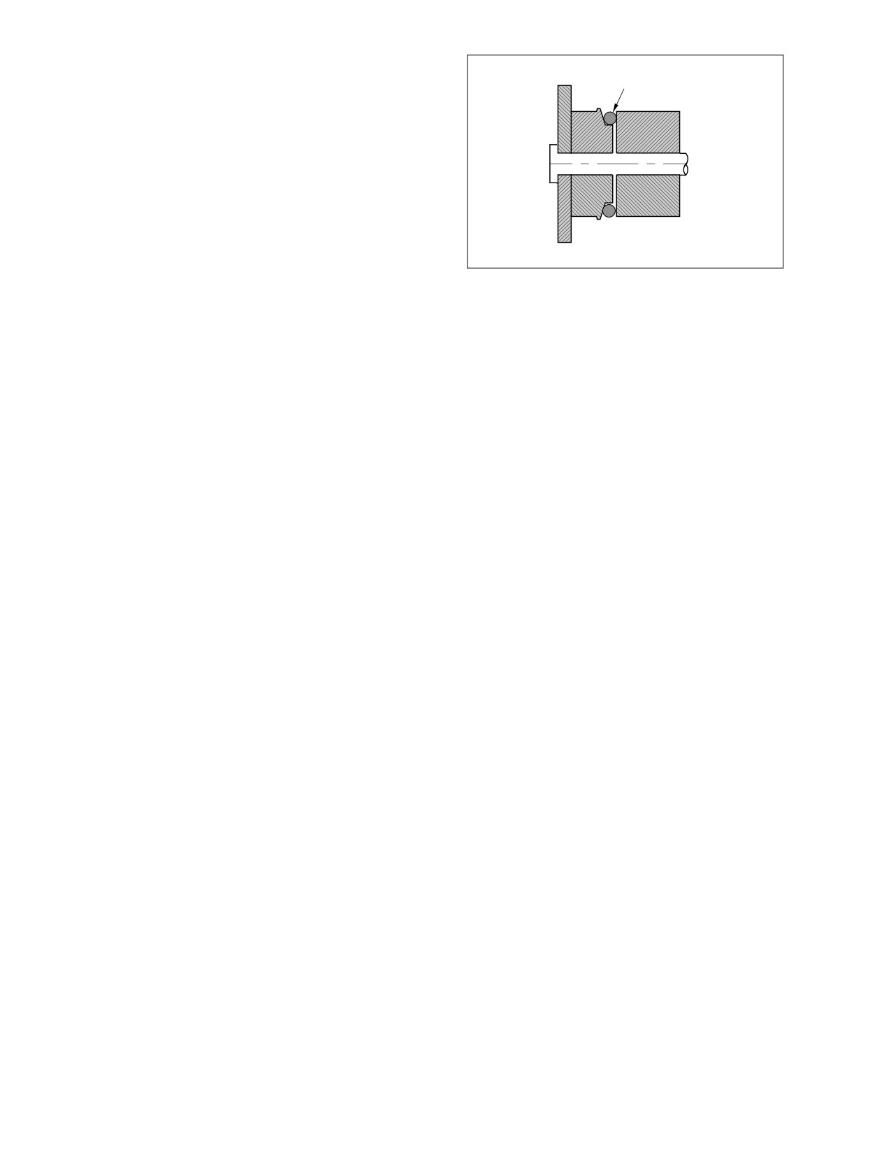
5.
Roll new O-ring (1, Figure 97) into O-ring
groove.
1
HAOC720L
Figure 97
4-62 Inspection, Maintenance and Adjustment
022-00031E Operation and Maintenance Manual