Doosan Solar 255LC-V. Operation and Maintenance Manual (2002) - page 1
Solar 255LC-V
Operation and Maintenance Manual
022-00031E
Serial Number 1001 and Up
August 2002
Daewoo reserves the right to improve our products in a continuing process to provide the best possible
product to the market place. These improvements can be implemented at any time with no obligation to
change materials on previously sold products. It is recommended that consumers periodically contact their
distributors for recent documentation on purchased equipment.
This documentation may include attachments and optional equipment that is not available in your
machine’s package. Please call your distributor for additional items that you may require.
Illustrations used throughout this manual are used only as a representation of the actual piece of
equipment, and may vary from the actual item.
022-00031E Operation and Maintenance Manual
TABLE OF CONTENTS
Safety
1-1
To the Operator of a Daewoo Excavator
1-1
Location of Safety Labels
1-4
Summary of Safety Precautions for Lifting in Digging Mode
1-12
Unauthorized Modifications
1-13
General Hazard Information
1-13
Before Starting Engine
1-21
Machine Operation
1-24
Maintenance
1-29
Battery
1-37
Towing
1-39
Shipping and Transportation
1-40
Excavator Rated Lift Capacity Tables
1-41
Operating Controls
2-1
Component Locations
2-2
Operator’s Area
2-4
Operational Controls and Panels
2-5
Instrument Panel
2-14
Multifunction Gauge and Graphic Information
2-19
Mode Selection Buttons
2-23
Setting Method for Main Menu
2-26
Heater and Air Conditioner Control Panel
2-30
Stereo
2-35
Fuse Boxes
2-42
Miscellaneous Electrical Devices
2-43
Seat Adjustment
2-45
Seat Belt
2-47
Ceiling Cover
2-48
Front Windows
2-49
022-00031E Operation and Maintenance Manual
Table of Contents I
Door Side Latch
2-52
Miscellaneous Access Covers and Doors
2-53
Cab Storage Compartments
2-54
Ashtray
2-54
Emergency Glass Breaking Tool
2-55
Operation
3-1
To Handle a New Excavator
3-1
Starting and Stopping the Engine
3-2
Safety Lever
3-14
Travel
3-15
Operating Instructions
3-20
Operating Precautions
3-25
Parking Excavator
3-30
Towing Procedure
3-31
Hydraulic Breaker
3-32
Operating Techniques
3-36
Operation Under Unusual Conditions
3-38
Inspection, Maintenance and Adjustment
4-1
Preliminary Work Machine Setup for Maintenance
4-3
Table of Recommended Lubricants
4-5
Fluid Capacities
4-7
Lubrication and Service Chart
4-7
Maintenance Intervals
4-10
10 Hour / Daily Service
4-12
50 Hour / Weekly Service
4-22
250 Hour / Monthly Service
4-26
500 Hour / 3 Month Service
4-31
1000 Hour / 6 Month Service
4-39
2000 Hour / Yearly Service
4-45
4000 Hour / Biennial Service
4-48
12,000 Hour / Six Year Service
4-49
II Table of Contents
022-00031E Operation and Maintenance Manual
Venting and Priming Hydraulic System
4-50
Handling of Accumulator
4-52
Fuel Transfer Pump (Option)
4-53
Electrical System
4-55
Air Conditioning System
4-59
Bucket
4-60
Bucket Shimming Procedures
4-63
Track Tension
4-64
Bolt and Nut Inspection
4-66
Maintenance in Special Conditions
4-67
Long Term Storage
4-68
Transportation
5-1
Loading and Unloading
5-1
Lifting With Sling
5-4
Troubleshooting
6-1
Engine
6-1
Hydraulic System
6-2
Swing System
6-3
Travel System
6-4
Electrical System
6-4
Specification
7-1
Standard Specification
7-1
Overall Dimensions
7-2
Working Range
7-3
Approximate Weight of Workload Materials
7-4
Index
8-1
022-00031E Operation and Maintenance Manual
Table of Contents III
1SAFETY
TO THE OPERATOR OF A DAEWOO EXCAVATOR
DANGER!
Unsafe use of the excavator could lead to serious injury or death. Operating procedures,
maintenance and equipment practices or traveling or shipping methods that do not follow the
safety guidelines on the following pages could cause serious, potentially fatal injuries or
extensive damage to the machine or nearby property.
Please respect the importance of taking responsibility for your own safety, and that of other people who
may be affected by your actions.
The safety information on the following pages is organized into the following sections:
1.
“Location of Safety Labels” on page 1-4
2.
“Summary of Safety Precautions for Lifting in Digging Mode” on page 1-12
3.
“General Hazard Information” on page 1-13
4.
“Before Starting Engine” on page 1-21
5.
“Machine Operation” on page 1-24
6.
“Maintenance” on page 1-29
7.
“Battery” on page 1-37
8.
“Towing” on page 1-39
9.
“Shipping and Transportation” on page 1-40
10.
“Excavator Rated Lift Capacity Tables” on page 1-41
022-00031E Operation and Maintenance Manual
Safety 1-1
WARNING!
Improper operation and maintenance of this machine can be hazardous and could result in
serious injury or death.
Operator and maintenance personnel should read this manual thoroughly before beginning
operation or maintenance.
Keep this manual in the storage compartment to the rear of the operator’s seat, and have all
personnel involved in working on the machine read the manual periodically.
Some actions involved in operation and maintenance of the machine can cause a serious
accident, if they are not done in a manner described in this manual.
The procedures and precautions given in this manual apply only to intended uses of the
machine.
If you use your machine for any unintended uses that are not specifically prohibited, you must
be sure that it is safe for any others. In no event should you or others engage in prohibited uses
or actions as described in this manual.
Daewoo delivers machines that comply with all applicable regulations and standards of the
country to which it has been shipped. If this machine has been purchased in another country or
purchased from someone in another country, it may lack certain safety devices and
specifications that are necessary for use in your country. If there is any question about whether
your product complies with the applicable standards and regulations of your country, consult
Daewoo or your Daewoo distributor before operating the machine.
1-2 Safety
022-00031E Operation and Maintenance Manual
SAFETY ALERT SYMBOL
Be Prepared - Get To Know All Operating and Safety Instructions.
This is the Safety Alert Symbol. Wherever it appears in this manual or on safety signs on the
machine you should be alert to the potential for personal injury or accidents. Always observe
safety precautions and follow recommended procedures.
LEARN THE SIGNAL WORDS USED WITH THE SAFETY ALERT SYMBOL
The words "CAUTION," "WARNING," and "DANGER" used throughout this manual and on decals on the
machine indicate degree of risk of hazards or unsafe practices. All three degrees of risk indicate that safety
is involved. Observe precautions indicated whenever you see the Safety Alert "Triangle," no matter which
signal word appears next to the "Exclamation Point" symbol.
CAUTION!
This word is used on safety messages and safety labels and indicates potential of a hazardous
situation that, if not avoided, could result in minor or moderate injury. It may also be used to alert
against a generally unsafe practice.
WARNING!
This word is used on safety messages and safety labels and indicates potential of a hazardous
situation that, if not avoided, could result in serious injury or death. It may also be used to alert
against a highly unsafe practice.
DANGER!
This word is used on safety messages and safety labels and indicates an imminent hazard of a
situation that, if not avoided, is very likely to cause death or extremely serious injury. It may also
be used to alert against equipment that may explode or detonate if handled or treated carelessly.
Safety precautions are described in SAFETY from page 1-4 on.
Daewoo cannot predict every circumstance that might involve a potential hazard in operation and
maintenance. Therefore the safety messages in this manual and on the machine may not include all
possible safety precautions. If any procedures or actions not specifically recommended or allowed in this
manual are used, you must be sure that you and others can do such procedures and actions safely and
without damaging the machine. If you are unsure about the safety of some procedures, contact a
DAEWOO distributor.
022-00031E Operation and Maintenance Manual
Safety 1-3
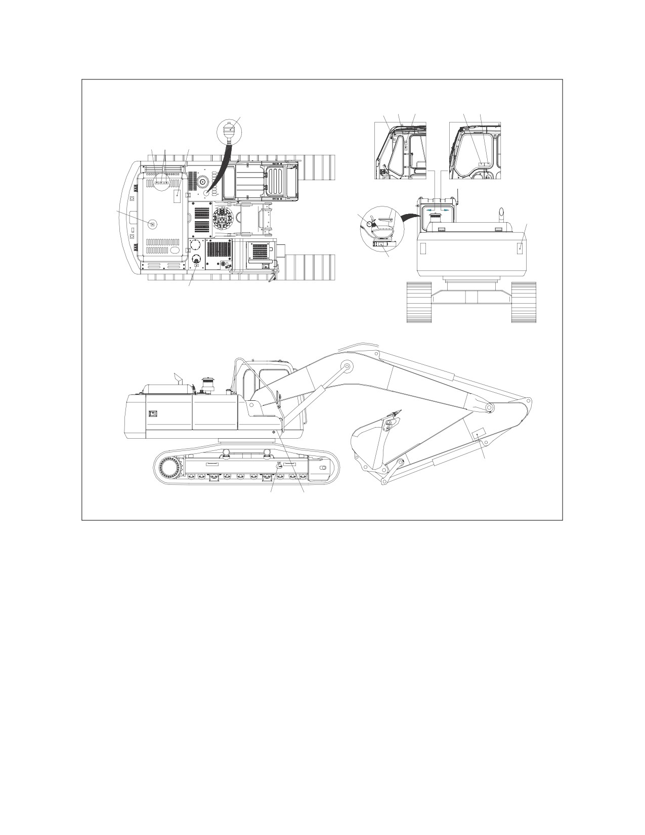
LOCATION OF SAFETY LABELS
3
6
5
1
2
10
9
11
14
13
12
15
5
8
16
4
7
AYO0010L
Figure 1
There are several specific warning signs on this machine. The exact location of hazards and the
description of the hazards are reviewed in this section.
Please become familiarized with all warning signs.
Make sure that all of the warning signs are legible. Clean the warning signs or replace the warning signs if
you cannot read the words. Replace the illustrations if the illustrations are not visible. When you clean the
warning signs, use a cloth, water and soap. Do not use solvent, gasoline, or other harsh chemicals to clean
the safety signs. Solvents, gasoline, or other harsh chemicals could loosen the adhesive that secures the
warning sign. Loose adhesive will allow the warning sign to fall off.
Replace any safety sign that is damaged, or missing. If a safety sign is attached to a part that is replaced,
install a safety sign on the replacement part.
1-4 Safety
022-00031E Operation and Maintenance Manual
1.
WARNINGS FOR OPERATION, INSPECTION AND MAINTENANCE (190-00688, 190-00092).
AVOID DEATH OR SERIOUS INJURY. - READ AND UNDERSTAND
OPERATION MANUAL AND SAFETY LABELS prior to operating
this machine.
Never get in under the machine while it is being jacked up
with boom and arm.
Sound the horn to alert the people nearby before operating,
and make sure that all persons are clear of area.
190-00092
Controls may be changed for attachments or operator
preference. Try control pattern before operating.
190-00688
ARO1080L
2.
WARNINGS FOR HIGH VOLTAGE (190-00689, 190-00096)
DANGER
SERIOUS INJURY OR DEATH BY
ELECTROCTION can occur if
machine or attachments are
not a safe distance from electrical
power lines.
Line voltage
Safe Distance
6.6 kv
At least 3m(10ft)
66.6 kv
At least 5m(16ft)
190-00096
275.0 kv
At least 10m(33ft)
190-00689
ARO1090L
3.
WARNINGS WHEN OPENING A FRONT WINDOW (190-00690, 190-00093).
Falling window can cause
injury.
When raising window,
lock it in place with lock
pin on left side.
190-00690
190-00093
ARO1100L
022-00031E Operation and Maintenance Manual
Safety 1-5
4.
WARNINGS FOR A HIGH PRESSURE
CYLINDER (190-00122).
190-00122
ARO1110L
5.
WARNINGS WHEN ADJUSTING TRACK TENSION (2190-3386A, 190-00521).
The track adjuster adjustment and handling
The spring in the track adjuster is loaded with great force
and the pressure in the cylinder is very high. For this
reason there is a possibility of an accident which
may involve injury to personnel. It is very dangerous
to make mistakes when performing such an adjustment
or disassembly.
Be sure to read the procedures described in the Operation
and Maintenance Manual carefully before adjusting the
track tension.
2190-3386A
190-00521
ARO1120L
1-6 Safety
022-00031E Operation and Maintenance Manual
6.
WARNINGS FOR LEAVING OPERATOR’S SEAT (190-00693, 190-00094).
Sudden and unwanted machine
movement can cause serious
injury or death.
Always make sure when leaving
operator's seat to :
Lower equipment to the ground.
Move safety lever to LOCK position.
Turn key switch OFF. Remove key
from switch.
190-00693
190-00094
ARO1140L
7.
WARNINGS FOR BATTERIES MAINTENANCE (2190-2533A, 190-00100).
Battery fumes can explode. Keep sparks and flames away
from batteries.
Always avoid storing metals like tools or flammable
materials around or on the batteries. Explosion or fire
can be caused by shortcircuiting batteries.
Surfuric acid in battery is poisonous. It is strong enough
burn skin, eat holes in clothing, and cause blindness
if splashed eyes.
If you spill acid on yourself;
1. Flush your skin with water.
2. Apply baking soda or lime to help neutralize the acid.
3. Flush your eyes with water for 10-15 minutes.
Get medical attention immediately.
2190-2533A
190-00100
ARO1150L
022-00031E Operation and Maintenance Manual
Safety 1-7
8.
WARNINGS FOR HIGH TEMPERATURE HYDRAULIC OIL (190-00691, 190-00097)
HOT OIL CAN CAUSE INJURY OR
BLINDNESS.
To prevent hot oil from spurting out:
Tur n engine off
Allow oil to cool
190-00097
Slowly loosen cap to relieve
pressure
190-00691
ARO1160L
9.
WARNINGS FOR HOT COOLANT (190-00692, 190-00097)
HOT COOLANT CAN CAUSE INJURY
OR BLINDNESS.
Never loosen or open radiator cap
when coolant is hot and under
pressure.
To open cap, stop engine, wait until
radiator is cool. Then loosen cap
190-00097
slowly to relieve the pressure.
190-00692
ARO1170L
10. WARNINGS FOR HANDLING AN ACCUMULATOR (190-00703, 190-00099).
Keep away from flame.
Do not weld on, or drill
into the accumulator.
EXPLOSION HAZARD
190-00703
190-00099
ARO1180L
1-8 Safety
022-00031E Operation and Maintenance Manual
11. WARNINGS FOR ROTATING PARTS (190-00694, 190-00095, 190-00557).
190-00095
Rotating parts can cause
personal injury.
Keep away from fan and
belt when engine is run-
ning. Stop engine before
servicing.
190-00694
190-00557
ARO1190L
12. WARNING TAG - USED WHEN INSPECTION AND MAINTENANCE (190-00695, 190-00098).
WARNING
DO NOT OPERATE
when performing inspection
or maintenance
190-00695
190-00098
ARO1200L
022-00031E Operation and Maintenance Manual
Safety 1-9
13. WARNING FOR A HOT SURFACE
(190-00648).
190-00648
ARO1210L
14. CAUTION FOR HOOD (190-00522).
190-00522
ARO1220L
15. KEEP OUT OF THE SWING AREA (2190-3379, 190-00090).
2190-3379
190-00090
ARO1240L
1-10 Safety
022-00031E Operation and Maintenance Manual
16. WARNINGS FOR FRONT
ATTACHMENTS (190-00652).
190-00652
ARO1230L
022-00031E Operation and Maintenance Manual
Safety 1-11
SUMMARY OF SAFETY PRECAUTIONS FOR LIFTING
IN DIGGING MODE
DANGER!
Unsafe use of the excavator while making rated lifts could cause serious, potentially fatal
injuries or extensive damage to the machine or nearby property. Do not let anyone operate the
machine unless they’ve been properly trained and understand the information in the Operation
and Maintenance Manual.
To lift safely while in Digging Mode, the following items must be evaluated by the operator and the work site
crew.
•
Condition of ground support.
•
Excavator configuration and attachments.
•
Weight, lifting height and lifting radius.
•
Safe rigging of the load.
•
Proper handling of the suspended load.
Taglines on opposite sides of the load can be very helpful in keeping a suspended load secure, if they are
anchored safely to control points on the ground.
WARNING!
NEVER wrap a tagline around your hands or body.
NEVER rely on taglines or make rated lifts when wind gusts are more than 48.3 km/hr (30 mi/h).
Be prepared for any type of wind gust when working with loads that have a large surface area.
Always engage the "Digging Mode" control on the Instrument Panel before using the excavator for lifting
work.
WARNING!
If you need more information or have any questions or concerns about safe operating
procedures or working the excavator correctly in a particular application or in the specific
conditions of your individual operating environment, please consult your local Daewoo
representative.
1-12 Safety
022-00031E Operation and Maintenance Manual
UNAUTHORIZED MODIFICATIONS
Any modification made without authorization or written approval from Daewoo can create a safety hazard,
for which the machine owner must be held responsible.
For safety’s sake, replace all OEM parts with the correct authorized or genuine Daewoo part. For example,
not taking the time to replace fasteners, bolts or nuts with the correct replacement parts could lead to a
condition in which the safety of critical assemblies is dangerously compromised.
GENERAL HAZARD INFORMATION
SAFETY RULES
Only trained and authorized personnel can operate and maintain the machine.
Follow all safety rules, precautions and instructions when operating or performing maintenance on the
machine.
Do not operate the machine if you are not feeling well, if you are taking medication that makes you feel
sleepy, if you have been drinking, or if you are suffering from emotional problems. These problems will
interfere with your sense of judgement in emergencies and may cause accidents.
When working with another operator or with a person on work site traffic duty, be sure that all personnel
know the nature of the work and understand all hand signals that are to be used.
Always observe strictly any other rules related to safety.
SAFETY FEATURES
Be sure that all guards and covers are installed in their proper position. Have guards and covers repaired
immediately if damaged.
Be sure that you understand the method of use of safety features such as safety lock lever and the seat
belt, and use them properly.
Never remove any safety features. Always keep them in good operating condition.
Failure to use safety features according to the instructions in the Operation and Maintenance Manual could
result in serious bodily injury.
022-00031E Operation and Maintenance Manual
Safety 1-13
INSIDE OPERATOR'S COMPARTMENT
When entering the operator's compartment, always remove all mud and oil from the soles of your shoes. If
you operate the travel pedal with mud or oil stuck to your shoes, your foot may slip and this may cause a
serious accident.
After using the ashtray, make sure that any matches or cigarettes are properly extinguished, and be sure to
close the ashtray. If the ashtray is left open, there is danger of fire.
Do not stick suction pads to the window glass. Suction pads act as a lens and may cause fire.
Do not leave lighters laying around the operator's compartment. If the temperature inside the operator's
compartment becomes high, there is danger that the lighter may explode.
Do not use cellular telephones inside the operator's compartment when driving or operating the machine.
There is danger that this may lead to an unexpected accident.
Never bring any dangerous objects such as flammable or explosive items into the operator's cab.
To ensure safety, do not use the radio or music headphones when operating the machine. There is danger
that this may lead to a serious accident.
When operating the machine, do not put your hands or head out of the window.
When standing up from the operator's seat, always place safety lock lever securely in the "LOCK" position.
If you accidentally touch the work equipment levers when they are not locked, the machine may suddenly
move and cause serous injury or damage.
When leaving the machine, lower the work equipment completely to the ground, set safety lock lever to the
"LOCK" position and shut down engine. Use the key to lock all the equipment. Always remove the key and
take it with you.
CLOTHING AND PERSONAL PROTECTIVE
ITEMS
Contain long hair, and avoid loose clothing and
jewelry. They can catch on controls or in
protruding parts and cause serious injury or
death.
Do not wear oily clothes. They are highly
flammable.
Full eye protection, a hard hat, safety shoes and
gloves may be required at the work site.
HAOA020L
While working on the machine, never use
Figure 2
inadequate tools. They could break or slip,
causing injury, or they may not adequately
perform intended functions.
BREATHING MASKS, EAR PROTECTION MAY BE REQUIRED
Don’t forget that some risks to your health may not be immediately apparent. Exhaust gases and noise
pollution may not be visible, but these hazards can cause disabling or permanent injuries.
1-14 Safety
022-00031E Operation and Maintenance Manual
MOUNTING AND DISMOUNTING
Before getting on or off the machine, if there is any oil. grease, or mud on the handrails, steps, or track
shoes, wipe it off immediately. Always keep these parts clean. Repair any damage and tighten any loose
bolts.
Never jump on or off the machine. In particular, never get on or off a moving machine. These actions may
lead to serious injury.
When getting on or off the machine, always face the machine, and maintain three-point contact (both feet
and one hand or one foot and both hands) with the handrails, steps, and track shoes to ensure that you
support yourself securely.
Never hold any control levers when getting on or off the machine.
Apply the door lock securely. If you grip the handrail inside the door when moving on top of the track shoes,
and the door lock is not applied securely, the door may move and cause you to fall.
Use the points marked by arrows in the diagram when getting on or off the machine.
Figure 3
022-00031E Operation and Maintenance Manual
Safety 1-15
FUEL, OIL AND HYDRAULIC FLUID FIRE
HAZARDS
Fuel, oil and antifreeze will catch fire if it is
brought close to a flame. Fuel is particularly
flammable and can be hazardous.
Always strictly observe the following.
Add fuel, oil, antifreeze and hydraulic fluid to the
machine only in a well-ventilated area. The
machine must be parked with controls, lights
and switches turned "OFF." The engine must be
"OFF" and any flames, glowing embers,
auxiliary heating units or spark-causing
equipment must be doused, turned off and/or
kept well clear of the machine.
Static electricity can produce dangerous sparks
at the fuel filling nozzle. In very cold, dry
Figure 4
weather or other conditions that could produce a
static discharge, keep the tip of the fuel nozzle
in constant contact with the neck of the fuel
filling nozzle, to provide a ground.
Keep fuel and other fluid reservoir caps tight and
do not start the engine until caps have been
secured.
PRECAUTIONS WHEN HANDLING FLUIDS
AT HIGH TEMPERATURE
Immediately after operations are stopped, the
coolant, engine oil, and hydraulic oil are at high
temperature and the radiator and hydraulic tank
are still under pressure. Attempting to remove
the cap, drain the oil or coolant, or replace the
filters may lead to serious burns. Always wait for
the temperature to go down, and follow the
specified procedures when carrying out these
operations.
HAOA050L
Figure 5
To prevent hot coolant from spurting out, shut
down engine, wait for the coolant to cool, then
loosen the cap slowly to relieve the pressure.
To prevent hot oil from spurting out, shut down
engine, wait for the oil to cool, then loosen the
cap slowly to relieve the pressure.
HAOA060L
Figure 6
1-16 Safety
022-00031E Operation and Maintenance Manual
ASBESTOS DUST HAZARD PREVENTION
Asbestos dust can be HAZARDOUS to your
health if it is inhaled. Materials containing
asbestos fiber can be present on work site.
Breathing air that contains asbestos fiber can
ultimately cause serious or fatal lung damage.
To prevent lung damage from asbestos fiber,
observe following precautions;
•
Use a respirator that is approved for
use
in
an
asbestos-laden
atmosphere.
ARO1770L
•
Never use compressed air for
Figure 7
cleaning.
•
Use water for cleaning to keep down
the dust.
•
Work on the machine or component
with the wind at your back whenever
possible.
•
Always observe any rules and
regulations related to the work site
and working environment.
INJURY FROM WORK EQUIPMENT
Do not enter or put your hand, arm or any other
part of your body between movable parts, such
as between the work equipment and cylinders,
or between the machine and work equipment.
If the control levers are operated, the clearance
between the machine and the work equipment
will change and this may lead to serious
damage or personal injury.
If going between movable parts is necessary,
always position and secure the work equipment
HDO1010L
so that it cannot move.
Figure 8
022-00031E Operation and Maintenance Manual
Safety 1-17
FIRE EXTINGUISHER AND FIRST AID KIT
As a precaution if any injury or fire should occur,
always do the following.
•
Be sure that fire extinguishers have
been provided and read the labels to
ensure that you know now to use
them. It is recommended that an
appropriately sized (2.27 kg [5 lb] or
larger) multipurpose "A/B/C" fire
extinguisher be mounted in the cab.
Check and service the fire
HDO1009L
extinguisher at regular intervals and
Figure 9
make sure that all work site crew
members are adequately trained in
its use.
•
Provide a first aid kit in the storage compartment and keep another at the work site. Check the
kit periodically and make any additions if necessary.
•
Know what to do in case of injury from fire.
•
Keep emergency numbers for doctor, ambulance service, hospital and fire department near
your telephone.
If the machine catches fire, it may lead to serious personal injury or death. If a fire occurs during operation,
escape from the machine as follows;
•
Turn the starter switch "OFF" and shut down engine.
•
If there is time, use the fire extinguisher to extinguish as much of the fire as possible.
•
Use the handrails and steps to escape from the machine.
The above is the basic method for escaping from the machine, but changing the method may be necessary
according to the conditions, so carry out practice drills at the work site.
PROTECTION FROM FALLING OR FLYING OBJECTS
On work sites where there is danger that falling objects or flying objects may hit the operator's cab select a
guard to match the operating conditions to protect the operator.
Working in mines, tunnels, deep pits or on loose
or wet surfaces could produce danger of falling
rock or hazardous flying objects. Additional
protection for the operator's cab could be
required in the form of a FOPS (Falling Object
Protective Structure) or window guards.
HAOA110L
Figure 10
1-18 Safety
022-00031E Operation and Maintenance Manual
Never attempt to alter or modify any type of
protective structure reinforcement system, by
drilling holes, welding, remounting or relocating
fasteners. Any serious impact or damage to the
system requires a complete integrity
reevaluation. Reinstallation, recertification and/
or replacement of the system may be
necessary.
Contact your Daewoo distributor for available
safety guards and/or recommendations if there
is any danger of getting hit by objects that could
strike the operator's cab. Make sure that all
HAOA100L
other work site crew members are kept well
Figure 11
away from the excavator and safe from possible
hazards.
For breaker operation, install a front guard and apply a laminated coating sheet to the front glass. Contact
your DAEWOO distributor for recommendations.
When carrying out demolition or cutting operation, install a front guard and top guard, and apply a
laminated coating sheet to the front glass.
When working in mines or quarries where there is danger of falling rock, install FOPS (Falling Objects
Protective Structure) and apply a laminated coating sheet to the front glass.
If any glass on the machine is broken, replace it with new glass immediately.
ATTACHMENT PRECAUTIONS
Option kits are available through your dealer. Contact Daewoo for information on available one-way (single-
acting) and two-way (double-acting) piping / valving / auxiliary control kits. Because Daewoo cannot
anticipate, identify or test all of the attachments that owners may wish to install on their machines, please
contact Daewoo for authorization and approval of attachments, and their compatibility with options kits.
ACCUMULATOR
The pilot control system is equipped with an accumulator. For a brief period of time after the engine has
been shut down, the accumulator will store a pressure charge that may enable hydraulic controls to be
activated. Activation of any controls may enable the selected function to operate under force of gravity.
When performing maintenance on the pilot control system, the hydraulic pressure in the system must be
released as describe in “Handling of Accumulator” on page 4-52.
The accumulator is charged with high-pressure nitrogen gas, so it is extremely dangerous if it is handled in
the wrong way. Always observe the following precautions;
•
Do not drill or make any holes in the accumulator or expose it any flame, fire or heat source.
•
Do not weld on the accumulator, or try attaching anything to it.
•
When carrying out disassembly or maintenance of the accumulator, or when disposing of the
accumulator, the charged gas must be properly released. Contact your Daewoo distributor.
•
Wear safety goggles and protective gloves when working on an accumulator. Hydraulic oil under
pressure can penetrate the skin and cause serious injuries.
022-00031E Operation and Maintenance Manual
Safety 1-19
INDOOR VENTILATION
Engine exhaust gases can cause fatal
accidents, and unconsciousness, loss of
alertness, judgement and motor control and
serious injury.
Make sure there is adequate ventilation before
starting the engine in any enclosed area.
You should also be aware of open windows,
doors or ductwork into which exhaust may be
carried, or blown by the wind, exposing others to
danger.
ARO1770L
Figure 12
EMERGENCY EXIT
This machine is equipped with a glass breaking
tool. It is behind the operator seat in the upper
right corner of the cab. This tool can be used in
case of an emergency situation that requires the
breaking of glass to exit from the operator’s
cabin. Grip the handle firmly and use the sharp
point to break the glass.
WARNING!
Figure 13
Protect your eyes when breaking the
glass.
1-20 Safety
022-00031E Operation and Maintenance Manual
BEFORE STARTING ENGINE
WORK SITE PRECAUTIONS
Before starting operations, thoroughly check the area for any unusual conditions that could be dangerous.
Check the terrain and condition of the ground at the work site, and determine the best and safest method of
operation.
Make the ground surface as hard and horizontal as possible before carrying out operations. If there is a lot
of dust and sand on the work site, spray water before starting operations.
If you need to operate on a street, protect
pedestrians and cars by designating a person
for work site traffic duty or by erecting fences
and posting "No Entry" signs around the work
site.
Erect fences, post "No Entry" signs, and take
other steps to prevent people from coming close
to or entering the work site. If people come
close to a moving machine, they may be hit or
caught by the machine, and this may lead to
serious personal injury or death.
ARO1250L
Water lines, gas lines, phone lines and high-
Figure 14
voltage electrical lines may be buried under the
work site. Contact each utility and identify their
locations. Be careful not to damage or cut any of
these lines.
Check the condition of the river bed, and the
depth and flow of the water before operating in
water or crossing a river. NEVER be in water
that is in excess of the permissible water depth.
Any type of object in the vicinity of the boom
could represent a potential hazard, or cause the
operator to react suddenly and cause an
accident. Use a spotter or signal person working
near bridges, phone lines, work site scaffolds, or
other obstructions.
Figure 15
022-00031E Operation and Maintenance Manual
Safety 1-21
Minimum levels of insurance coverage, work
permits or certification, physical barriers around
the work site or restricted hours of operation
may be mandated by governing authorities.
There may also be regulations, guidelines,
standards or restrictions on equipment that may
have to be followed for local requirements.
There may also be regulations related to
performing certain kinds of work. If there is any
question about whether your machine and work
site complies with the applicable standards and
regulations contact your local authorities and
agencies.
Figure 16
Avoid entering soft ground. It will be difficult for
the machine to escape.
Avoid operating your machine to close to the edge of cliffs, overhangs, and deep ditches. The ground may
be weak in such areas. If the ground should collapse, the machine could fall or tip over and this could result
in serious injury or death.
Remember that the soil after heavy rain, blasting or after earthquakes, is weakened in these areas.
Earth laid on the ground and the soil near ditches is loose. It can collapse under the weight of vibration of
your machine and cause your machine to tip over.
Install the head guard (FOPS) if working in areas where there is danger of falling rocks.
CHECKS BEFORE STARTING ENGINE
Every day before starting the engine for the first time, carry out the following checks. If these checks are
not carried out properly, there is danger of serious injury.
Completely remove all wood chips, leaves, grass, paper and other flammable materials accumulated in the
engine compartment and around the battery. They could cause a fire. Remove any dirt from the window
glass, mirrors, handrails, and steps.
Do not leave tools or spare parts laying around in the operator's compartment. The vibration of the
machine when traveling or during operations may cause them to fall and damage or break the control
levers or switches. They may also get caught in the gap of the control levers and cause the work equipment
to malfunction or move dangerously. This may lead to unexpected accidents.
Check the coolant level, fuel level, and hydraulic tank oil level, and check for clogged air cleaner and
damage to the electrical wiring.
Adjust the operator's seat to a position where it is easy to operate the machine, and check the seat belt and
mounts for damage and wear.
Check the operation of the gauges and the angle of the mirrors, and check that the safety lever is in
"LOCKED" position.
If any abnormalities are found in the above checks, carry out repairs immediately.
1-22 Safety
022-00031E Operation and Maintenance Manual
ENGINE STARTING
Walk around your machine before getting in the operator’s cab. Look for evidence of leaking fluid, loose
fasteners, misaligned assemblies or any other indications of possible equipment hazard.
All equipment covers and machinery safety guards must be in place, to protect against injury while the
machine is being operated.
Look around the work site area for potential hazards, people or properly that could be at risk while
operation is in progress.
NEVER start the engine if there is any indication that maintenance or service work is in progress, or if a
warning tag is attached to controls in the cab.
A machine that has not been used recently, or is being operated in extremely cold temperatures, could
require a warm-up or maintenance service before start-up.
Check gauges and monitor displays for normal operation before starting the engine. Listen for unusual
noises and remain alert for other potentially hazardous conditions at the start of the work cycle.
Do not short circuit the starting motor to start the engine. This is not only dangerous, but may also damage
the machine.
When starting the engine, sound the horn as an alert.
Start and operate the machine only while seated.
BEFORE OPERATING MACHINE
If checks are not carried out properly after starting the engine, it may result in a delay in discovering
abnormalities in the machine, and this may lead to personal injury or damage to the machine.
Carry out the checks in an open area where there are no obstructions. Do not let anyone near the machine
when carrying out the checks.
•
Check the operating condition of the equipment, and the actuation of the bucket, arm, boom,
travel, and swing systems.
•
Check the machine for any abnormal noise, vibration, heat, smell, or abnormality with the
gauges. Check also for leakage of air, oil, and fuel.
•
If any abnormality is found, repair the problem immediately. If the machine is used without
repairing the problems, it may lead to unexpected injury or failure.
•
Clear all personnel from directly around machine and from the area.
•
Clear all obstacles from the machine's path. Beware of hazards.
•
Be sure that all windows are clean. Secure the doors and the windows in the open position or in
the shut position.
•
Adjust the rear view mirrors for best visibility close to the machine. Make sure that the horn, the
travel alarm (if equipped), and all other warning devices are working properly.
•
Fasten the seat belt securely.
•
Warm up the engine and hydraulic oil before operating machine.
•
Before moving the machine, check the position of undercarriage. The normal travel position is
with idler wheels to the front under the cab and the drive sprockets to the rear. When the
undercarriage is in the reversed position, the travel controls must be operated in opposite
directions.
022-00031E Operation and Maintenance Manual
Safety 1-23
MACHINE OPERATION
WHEN SWINGING OR CHANGING
DIRECTION OF TRAVEL
Before operating the machine or the work
equipment, always observe the following
precautions to prevent serious injury or death.
•
When changing the direction of travel
from forward to reverse or from
reverse to forward, reduce speed
early and stop the machine before
changing the direction of travel.
•
Sound the horn to warn people in the
HAOA190L
area.
Figure 17
•
Check that there is no one in the area
around the machine. There are blind spots behind the machine, so if necessary, swing the
upper structure to check that there is no one behind the machine before traveling in reverse.
•
When operating in areas that may be hazardous or have poor visibility, designate a person to
direct work site traffic.
•
Ensure that no unauthorized person can come within the turning radius or direction of travel.
Be sure to observe the above precautions even if a travel alarm or mirrors are installed.
TRAVEL PRECAUTIONS
Never turn the starting switch to the "O" (OFF) position when traveling. It is dangerous if the engine stops
when the machine is traveling. It will be impossible to operate the steering.
Attachment control levers should not be operated while traveling.
Do not change selected travel mode (FAST/SLOW) while traveling.
Fold in work equipment so that the outer end of the boom is as close to the machine as possible, and is 40-
50 cm (16 - 20 in) above ground.
Never travel over obstacles or slopes that will cause the machine to tilt severely. Travel around any slope or
obstacle that causes the machine to tilt 10 degrees or more to the right or left, or 30 degrees or more from
front to rear.
Do not operate the steering suddenly. The work equipment may hit the ground and cause the machine to
lose its balance, and this may damage the machine or structures in the area.
When traveling on rough ground, travel at low speed, and avoid sudden changes in direction.
Always keep to the permissible water depth. Permissible water depth is to the centerline of the upper track
rollers.
When traveling over bridges or structures on private land, check first that the bridge or structure can
withstand the weight of the machine. When traveling on public roads, check with the local authorities and
follow their instructions.
1-24 Safety
022-00031E Operation and Maintenance Manual
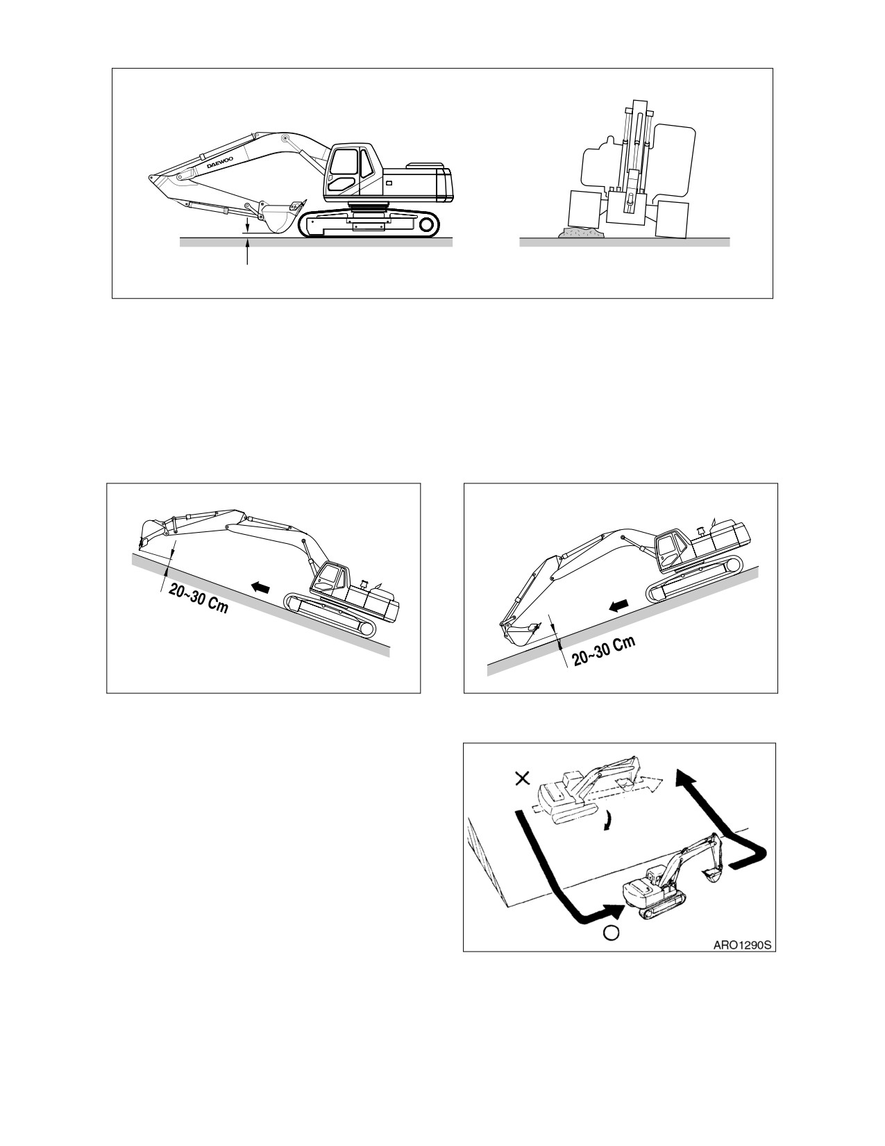
TRAVEL POSTURE
INCORRECT
40 ~ 50 cm (16 ~ 20 in.)
ARO1280L
Figure 18
TRAVELING ON SLOPES
Never jump onto a machine that is running away to stop it. There is danger of serious injury.
Traveling on slopes could result in the machine tipping over or slipping.
On hills, banks or slopes, carry the bucket approximately 20 - 30 cm (8 - 12 in) above the ground. In case
of an emergency, quickly lower the bucket to the ground to help stop the machine.
HAOB610L
HAOB620L
Figure 19
Figure 20
Do not travel on grass, fallen leaves, or wet steel
plates. Even slight slopes may cause the
machine to slip to the side, so travel at low
speed and make sure that the machine is
always traveling directly up or down the slope.
Avoid changing the direction of travel on a slope.
This could result in tipping or side slipping of the
machine.
When possible, operate the machine up slopes
and down slopes. Avoid operating the machine
across the slope, when possible.
Figure 21
022-00031E Operation and Maintenance Manual
Safety 1-25
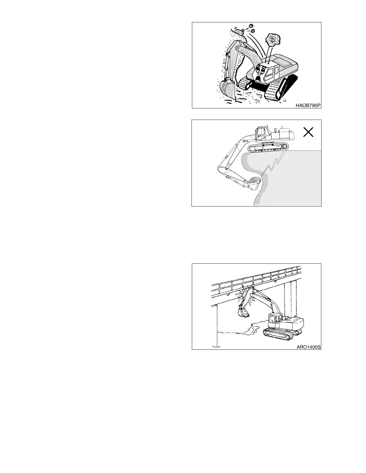
PROHIBITED OPERATIONS
Do not dig the work face under an overhand.
This may cause the overhand to collapse and
fall on top of the machine.
Figure 22
Do not carry out deep digging under the front of
the machine. The ground under the machine
may collapse and cause the machine to fall.
Working heavy loads over loose, soft ground or
uneven, broken terrain can cause dangerous
side load conditions and possible tipover and
injury. Travel without a load or a balanced load
may also be hazardous.
Never relay on lift jacks or other inadequate
supports when work is being done. Block tracks
fore and aft to prevent any movement.
ARO0950L
When using the machine, to prevent accidents
Figure 23
caused by damage to the work equipment and
overturning because of an excessive load, do
not use the machine in excess of its ability (in
terms of the maximum load and stability
determined by the structure of the machine).
PRECAUTIONS FOR OPERATION
Be careful not to go close to the edge of a cliff
by mistake.
Use the machine only for its main purpose.
Using it for other purposes will cause failures.
To ensure an ample view, do as follows:
•
When working in dark areas, attach
working lights and front lights to the
machine. If necessary, set up lighting
at the work site.
•
Stop operations when the visibility is
Figure 24
poor, such as in fog, mist, snow, and
rain. Wait for the visibility to improve
to a level which causes no problems
for the operation.
1-26 Safety
022-00031E Operation and Maintenance Manual
To avoid hitting the work equipment, always do the following;
•
When working in tunnels, on bridges, under electric wires, or when parking the machine or
carrying out other operations in places with limited height, be extremely careful not to hit the
bucket or other parts.
•
To prevent collisions, operate the machine at a safe speed when working in confined spaces,
indoors, or in crowded areas.
•
Do not pass the bucket over the heads of workers or over the operator's compartment of dump
truck.
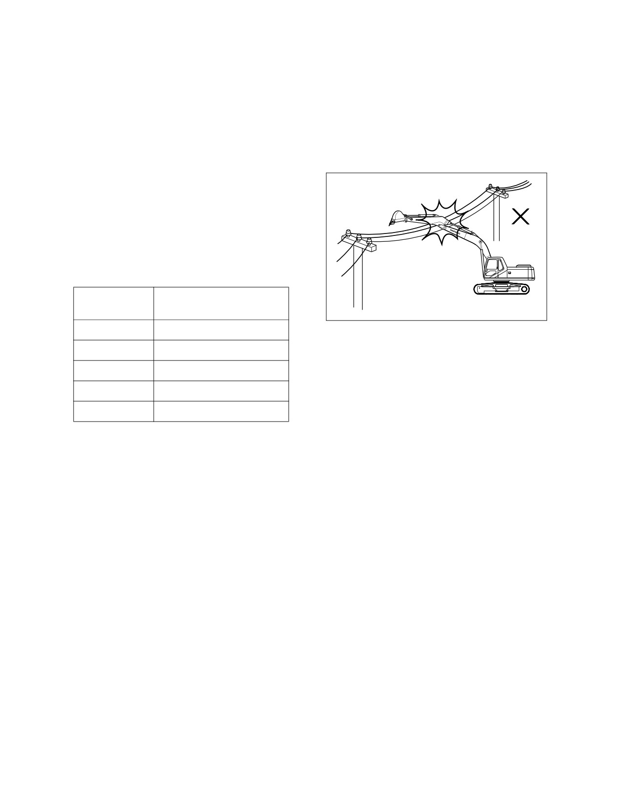
AVOID HIGH-VOLTAGE CABLES
Serious injury or death can result from contact
or proximity to high-voltage electric lines. The
bucket does not have to make physical contact
with power lines for current to be transmitted.
Use a spotter and hand signals to stay away
from power lines not clearly visible to the
operator.
VOLTAGE
MINIMUM SAFE
DISTANCE
HAOA230L
6.6 kV
3 m (9’ 10")
Figure 25
33.0 kV
4 m (13’ 1")
66.0 kV
5 m (16’ 5")
154.0 kV
8 m (26’ 3")
275.0 kV
10 m (32’ 10")
Use these minimum distances as a guideline only. Depending upon the voltage in the line and atmospheric
conditions, strong current shocks can occur with the boom or bucket as far away as 4 - 6 m (13 - 20 ft.)
from the power line. Very high voltage and rainy weather could further decrease that safety margin.
NOTE: Before starting any type of operation near power lines (either above ground or buried
cable-type), you should always contact the power utility directly and work out a safety plan
with them.
OPERATE CAREFULLY ON SNOW, ICE AND IN VERY COLD TEMPERATURES
In icy cold weather avoid sudden travel movements and stay away from even slight slopes. The machine
could skid off to one side very easily.
Snow accumulation could hide or obscure potential hazards. Use care while operating or while using the
machine to clear snow.
Warming up the engine for a short period may be necessary, to avoid operating with sluggish or reduced
working capacity. The jolting shocks and impact loads caused by bumping or bottoming the boom or
attachment are more likely to cause severe stress in very cold temperatures. Reducing work cycle rate and
work load may be necessary.
When the temperature rises, frozen road surfaces become soft, so the machine travel becomes unstable.
In cold weather, do not touch metal surfaces with your bare hands. If you touch a metal surface in
extremely cold weather, your skin may freeze to the metal surface.
022-00031E Operation and Maintenance Manual
Safety 1-27
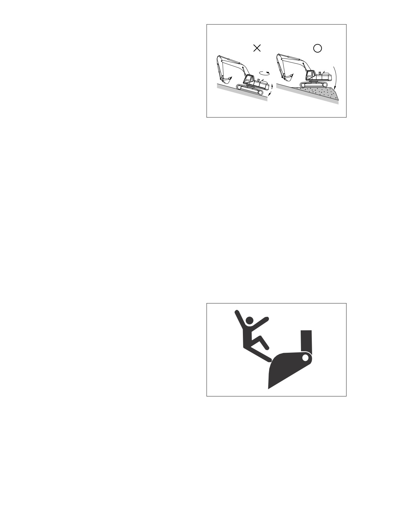
OPERATIONS ON SLOPES
When working on slopes. there is danger that
the machine may lose its balance and turn over,
when swinging, or when work equipment is
operated. Always carry out these operations
carefully.
Do not swing the work equipment from the uphill
side to the downhill side when the bucket is
loaded. This operation is dangerous.
If the machine has to be used on a slope, pile
the soil to make a platform that will keep the
HAOB600L
machine as horizontal as possible.
Figure 26
In addition, lower the bucket as far as possible,
keep it pulled into the front, and keep the swing
speed as low as possible.
PARKING MACHINE
Avoid making sudden stops, or parking the machine wherever it happens to be at the end of the work day.
Plan ahead so that the excavator will be on firm, level ground away from traffic and away from high walls,
cliff edges and any area of potential water accumulation or runoff. If parking on inclines is unavoidable,
block the crawler tracks to prevent movement. Lower the bucket or other working attachment completely to
the ground, or to an overnight support saddle. There should be no possibility of unintended or accidental
movement.
When parking on public roads, provide fences, signs, flags, or lights, and put up any other necessary signs
to ensure that passing traffic can see the machine clearly, and park the machine so that the machine, flags,
and fences do not obstruct traffic.
After the front attachment has been lowered to an overnight storage position and all switches and
operating controls are in the "OFF" position, the safety lock lever must be set to the "LOCKED" position.
This will disable all pilot circuit control functions.
Always close the door of the operator’s compartment.
NEVER LET ANYONE RIDE ON
ATTACHMENT
Never let anyone ride on any work attachment,
such as the bucket, crusher, grapple, or
clamshell (grab bucket). There is a danger of the
person falling and suffering serious injury.
ARO1310L
Figure 27
1-28 Safety
022-00031E Operation and Maintenance Manual
MAINTENANCE
WARNING TAG
Alert others that service or maintenance is
being performed and tag operator’s cab controls
- and other machine areas if required - with a
warning notice. OSHA mandated control lever
WARNING
lockout can be made with any OSHA certified
DO NOT OPERATE
lockout device and a length of chain or cable to
keep the left hand control console in the fully
when performing inspection
raised, non-active position.
or maintenance
Warning tags, for controls are available from
190-00695
Daewoo distributors.
ARO1320L
Figure 28
CLEAN BEFORE INSPECTION OR
MAINTENANCE
Clean the machine before carrying out inspection and maintenance. This prevents dirt from getting into the
machine and also ensures safety during maintenance.
If inspection and maintenance are carried out when the machine is dirty, it will become more difficult to
locate the problems, and also there is danger that you may get dirt or mud in your eyes or that you may slip
and injure yourself.
When washing the machine, do the following;
•
Wear shoes with non-slip soles to prevent yourself from slipping and falling on wet places.
•
Wear safety glasses and protective clothing when washing the machine with high-pressure
steam.
•
Take action to prevent touching high-pressure water and cutting your skin or having mud fly into
your eyes.
•
Do not spray water directly on electrical components (sensors, connector) (1, Figure 29). If
water gets into the electrical system, there is danger that it will cause defective operation and
malfunction.
Figure 29
Pick up any tools or hammers that are laying in the work place, wipe up any grease or oil or any other
slippery substances, and clean the area to make it possible to carry out the operation in safety. If the work
place is left untidy, you may trip or slip and suffer injury.
022-00031E Operation and Maintenance Manual
Safety 1-29
PROPER TOOLS
Use only tools suited to the task. Using
damaged, low qualify, faulty, or makeshift tools
could cause personal injury. There is danger
that pieces from, chisels with crushed heads, or
hammers, may get into your eyes and cause
blindness.
HDO1037L
Figure 30
USE OF LIGHTING
When checking fuel, oil, battery electrolyte, or
window washing fluid, always use lighting with
anti-explosion specifications. If such lighting
equipment is not used, there is danger of
explosion.
If work is carried out in dark places without
using lighting, it may lead to injury, so always
use proper lighting.
Even if the place is dark, never use a lighter or
flame instead of lighting. There is danger of fire.
HDO1040L
There is also danger that the battery gas may
Figure 31
catch fire and cause and explosion.
FIRE PREVENTION AND EXPLOSION PREVENTION
All fuels, most lubricants and some coolant mixtures are flammable. Leaking fuel or fuel that is spilled onto
hot surfaces or onto electrical components can cause a fire.
Store all fuels and all lubricants in properly marked containers and away from all unauthorized persons.
Store oily rags and other flammable material in a protective container.
Do not smoke while you refuel the machine or while you are in a refueling area.
Do not smoke in battery charging areas or in areas the contain flammable material.
Clean all electrical connections and tighten all electrical connections. Check the electrical wires daily for
wires that are loose of frayed. Tighten all lose electrical wires before you operate the machine. Repair all
frayed electrical wires before you operate the machine.
Remove all flammable materials before they accumulate on the machine.
Do not weld on pipes or on tubes that contain flammable fluids. Do not flame cut on pipes or on tubes that
contain flammable fluids. Before you weld on pipes or on tubes or before you flame cut on pipes or on
tubes, clean the pipes or tubes thoroughly with a nonflammable solvent.
1-30 Safety
022-00031E Operation and Maintenance Manual
BURN PREVENTION
When checking the radiator coolant level, shut down engine, let the engine and radiator cool down, then
check the coolant recovery tank. If the coolant level in the coolant recovery tank is near the upper limit,
there is enough coolant in the radiator.
Loosen the radiator cap gradually to release the internal pressure before removing the radiator cap.
ARO1360L
Figure 32
If the coolant level in the coolant recovery tank is below the lower limit, add coolant.
Cooling system conditioner contains alkali. Alkali can cause personal injury. Do not allow alkali to contact
the skin, the eyes, or the mouth.
Allow cooling system components to cool before you drain the cooling system.
Hot oil and hot components can cause personal injury. Do not allow hot oil or hot components to contact
the skin.
Remove the hydraulic tank filter plug only after the engine has been stopped. Make sure that the hydraulic
tank filter plug is cool before you remove it with your bare hand. Remove the hydraulic tank filter plug slowly
to relieve pressure.
Relieve all pressure in the hydraulic oil system, in the fuel system, or in the cooling system before you
disconnect any lines, fittings, or related items.
Batteries give off flammable fumes that can explode.
Do not smoke while you are checking the battery electrolyte levels.
Electrolyte is an acid. Electrolyte can cause personal injury. Do not allow electrolyte to contact the skin or
the eyes.
Always wear protective glasses when you work on batteries.
022-00031E Operation and Maintenance Manual
Safety 1-31
WELDING REPAIRS
When carrying out welding repairs, carry out the welding in a properly equipped place. The welding should
be performed by a qualified worker. During welding operations, there is the danger of, generation of gas,
fire, or electric shock, so never let an unqualified worker do welding.
The qualified welder must do the following;
•
To prevent explosion of the battery, disconnect the battery terminals and remove batteries.
•
To prevent generation of gas, remove the paint from the location of the weld.
•
If hydraulic equipment, piping or places close to them are heated, a flammable gas or mist will
be generated and there is danger of it catching fire. To avoid this, never subject these places to
heat.
•
Do not weld on pipes or on tubes that contain flammable fluids. Do not flame cut on pipes or on
tubes that contain flammable fluids. Before you weld on pipes or on tubes or before you flame
cut on pipes or on tubes, clean the pipes or tubes thoroughly with a nonflammable solvent.
•
If heat is applied directly to rubber hoses or piping under pressure, they may suddenly break so
cover them with a fireproof covering.
•
Wear protective clothing.
•
Make sure there is good ventilation.
•
Remove all flammable objects and provide a fire extinguisher.
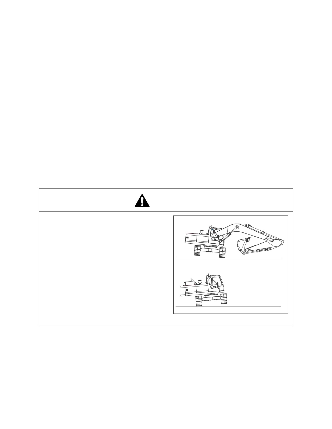
WARNING FOR COUNTERWEIGHT AND FRONT ATTACHMENT REMOVAL
DANGER!
Daewoo warns any user, that the removal of
the counterweight from the machine, front
X
attachment or any other part, may affect
the stability of the machine. This could
cause unexpected movement, resulting in
death or serious injuries. Daewoo is not
liable for any misuse.
Never remove the counterweight or front
attachment unless the upper structure is
X
in-line with the lower structure.
Never rotate the upper structure once the
counterweight or front attachment has
been removed.
HAAD4060
Figure 33
1-32 Safety
022-00031E Operation and Maintenance Manual
PRECAUTIONS FOR REMOVAL,
INSTALLATION, AND STORAGE OF
ATTACHMENTS
Before starting removal and installation of
attachments, decide the team leader.
Do not allow anyone except the authorized
workers close to the machine or attachment.
Place attachments that have been removed
from the machine in a safe place so that they do
not fall. Put up a fence around the attachments
and take other measures to prevent
HDO1041L
unauthorized persons from entering.
Figure 34
PRECAUTIONS WHEN WORKING ON
MACHINE
When carrying out maintenance operations on
the machine, keep the area around your feet
clean and tidy to prevent you from falling.
Always do the following;
•
Do not spill oil or grease.
•
Do not leave tools laying about.
•
Watch your step when walking.
Never jump down from the machine. When
ARO1380L
getting on or off the machine, use the steps and
Figure 35
handrails, and maintain a three-point contact
(both feet and one hand or both hands and one
foot) to support yourself securely.
If the job requires it, wear protective clothing.
To prevent injury from slipping or falling, when
working on the hood or covers, never use any
part except the inspection passage fitted with
non-slip pads.
LOCK INSPECTION COVERS
When carrying out maintenance with the inspection cover open, lock the cover securely in position with the
lock bar.
If maintenance work is carried out with the inspection cover open but not locked, there is danger that it may
suddenly close and cause injury if there is a gust of wind.
022-00031E Operation and Maintenance Manual
Safety 1-33
CRUSHING PREVENTION AND CUTTING PREVENTION
You should always have at least two people working together if the engine must be run during service. One
person needs to remain in the operator’s seat, ready to work the controls or stop the machine and shut off
the engine.
Unless you are instructed otherwise, never attempt adjustments while the machine is moving or while the
engine is running.
Stay clear of all rotating parts and moving parts.
Keep objects away from moving fan blades. The fan blades will throw objects and the fan blades can cut
objects.
Do not use a wire rope cable that is kinked or flayed. Wear gloves when you handle a wire rope cable.
When you strike a retainer pin, the retainer pin might fly out. The loose retainer pin can injure personnel.
Make sure that the area is clear of people when you strike a retainer pin. To avoid injury to your eyes, wear
protective glasses when you strike a retainer pin.
TRACK TENSION ADJUSTMENTS REQUIRE
CAUTION
Never turn out the track tension grease fitting
nut. To release pressure from the crawler frame
track tension assembly, you should NEVER
attempt to disassemble the track adjuster or
attempt to remove the grease fitting or valve
assembly.
Keep your face and body away from the valve.
Refer to the track adjustment procedure in the
Operator and Maintenance Manual or Shop
HAOA110L
Manual.
Figure 36
SUPPORTS AND BLOCKING FOR WORK
EQUIPMENT
Do not allow weight or equipment loads to
remain suspended. Lower everything to the
ground before leaving the operator’s seat. Do
not use hollow, cracked or unsteady, wobbling
weight supports. Do not work under any
equipment supported solely by a lift jack.
HDO1042L
Figure 37
1-34 Safety
022-00031E Operation and Maintenance Manual
ACTION WHEN ABNORMALLY IS FOUND DURING INSPECTION
If any abnormality is found during inspection, always carry out repairs. In particular, if the machine is used
when there are still problems with the brake or work equipment systems, it may lead to serious injury.
If necessary depending on the type of failure, please contact your Daewoo distributor for repairs.
PRECAUTIONS WITH HIGH PRESSURE LINE, TUBES AND HOSES
When inspecting or replacing high-pressure piping or hoses, check that the pressure has been released
form the circuit. Failure to release the pressure may lead to serious injury. Always do the following;
•
Wear protective glasses and leather gloves.
•
Fluid leaks from hydraulic hoses or pressurized components can be difficult to see but
pressurized oil has enough force to pierce the skin and cause serious injury. Always use a piece
of wood or cardboard to check for suspected hydraulic leaks. Never use your hands or expose
your fingers.
•
Do not bend high pressure lines. Do not strike high pressure lines. Do not install lines, tubes or
hoses that are bent or damaged.
•
Make sure that all clamps, guards and heat shields are installed correctly to prevent vibration,
rubbing against other parts, and excessive heat during operation.
- If any of the following conditions are found, replace the part.
- Damage or leakage from hose end.
- Wear, damage, cutting of covering, or exposure of strengthening wire layer.
- Cover portion is swollen in places.
- There is twisting or crushing at movable parts of hose.
- Foreign material is embedded in the covering.
- Hose end is deformed.
NOTE: Refer to “Hose In-service Lifetime Limit (European Standard ISO 8331 and EN982 CEN)”
on page 4-49, for additional European regulations.
X
X
O
HAOA420L
Figure 38
022-00031E Operation and Maintenance Manual
Safety 1-35
WASTE MATERIALS
Physical contact with used motor oil may pose a
X
health risk. Wipe oil from your hands promptly
and wash off any remaining residue.
Used motor oil is an environmental contaminant
and may only be disposed of at approved
collection facilities. To prevent pollution of the
environment, always do the following;
•
Never dump waste oil in a sewer
system, rivers, etc.
HAOA470L
•
Always put oil drained from your
Figure 39
machine in containers. Never drain
oil directly onto the ground.
•
Obey appropriate laws and
regulations when disposing of
harmful materials such as oil, fuel,
solvent, filters, and batteries.
1-36 Safety
022-00031E Operation and Maintenance Manual
BATTERY
BATTERY HAZARD PREVENTION
Battery electrolyte contains diluted sulfuric acid and batteries generate hydrogen gas. Hydrogen gas is
highly explosive, and mistakes in handling them can cause serious injury or fire. To prevent problems,
always do the following;
•
Do not smoke or bring any flame near the battery.
•
When working with batteries, ALWAYS wear safety glasses and rubber gloves.
•
If you spill battery electrolyte on yourself or your clothes, immediately flush the area with water.
•
If battery electrolyte gets into your eyes, flush them immediately with large quantities of water
and see a doctor at once.
•
If you accidentally drink battery electrolyte, drink a large quantity of water or milk, raw egg or
vegetable oil. Call a doctor or poison prevention center immediately.
•
When cleaning the top surface of the battery, wipe it with a clean, damp cloth. Never use
gasoline, thinner, or any other organic solvent or detergent.
•
Tighten the battery caps securely.
•
If the battery electrolyte is frozen, do not charge the battery or start the engine with power from
another source. There is danger that the battery may catch fire.
•
When charging the battery or starting with power from another source, let the battery electrolyte
melt and check that there is no leakage of battery electrolyte before starting the operation.
•
Always remove the battery from the machine before charging.
Figure 40
022-00031E Operation and Maintenance Manual
Safety 1-37
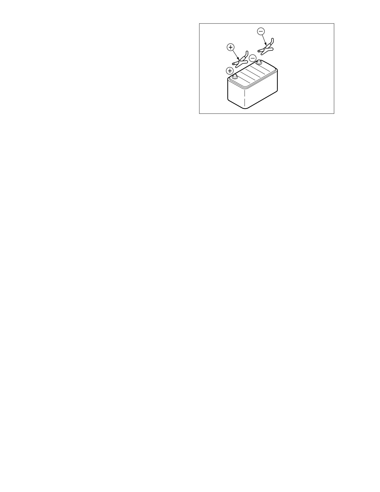
BOOST STARTING OR CHARGING ENGINE
BATTERIES
If any mistake is made in the method of
connecting the booster cables, it may cause an
explosion or fire. Always do the following;
•
Turn off all electrical equipment
before connecting leads to the
battery. This includes electrical
switches on the battery charger or
boost starting equipment.
•
When boost-starting from another
HAOA310L
machine or vehicle do not allow the
Figure 41
two machines to touch. Wear safety
glasses or goggles while required
battery connections are made.
•
24 volt battery units consisting of two series-connected twelve volt batteries have a cable
connecting one positive terminal on one of the 12 volt batteries to a negative terminal on the
other battery. Booster or charger cable connections must be made between the non-series-
connected positive terminals and between the negative terminal of the booster battery and the
metal frame of the machine being boosted or charged. Refer to the procedure and illustration in
“Starting Engine With a Booster Cable” on page 3-8 of this manual.
•
Connect positive cable first when installing cables and disconnect the negative cable first when
removing them. The final cable connection, at the metal frame of the machine being charged or
boost-started, should be as far away from the batteries as possible.
1-38 Safety
022-00031E Operation and Maintenance Manual
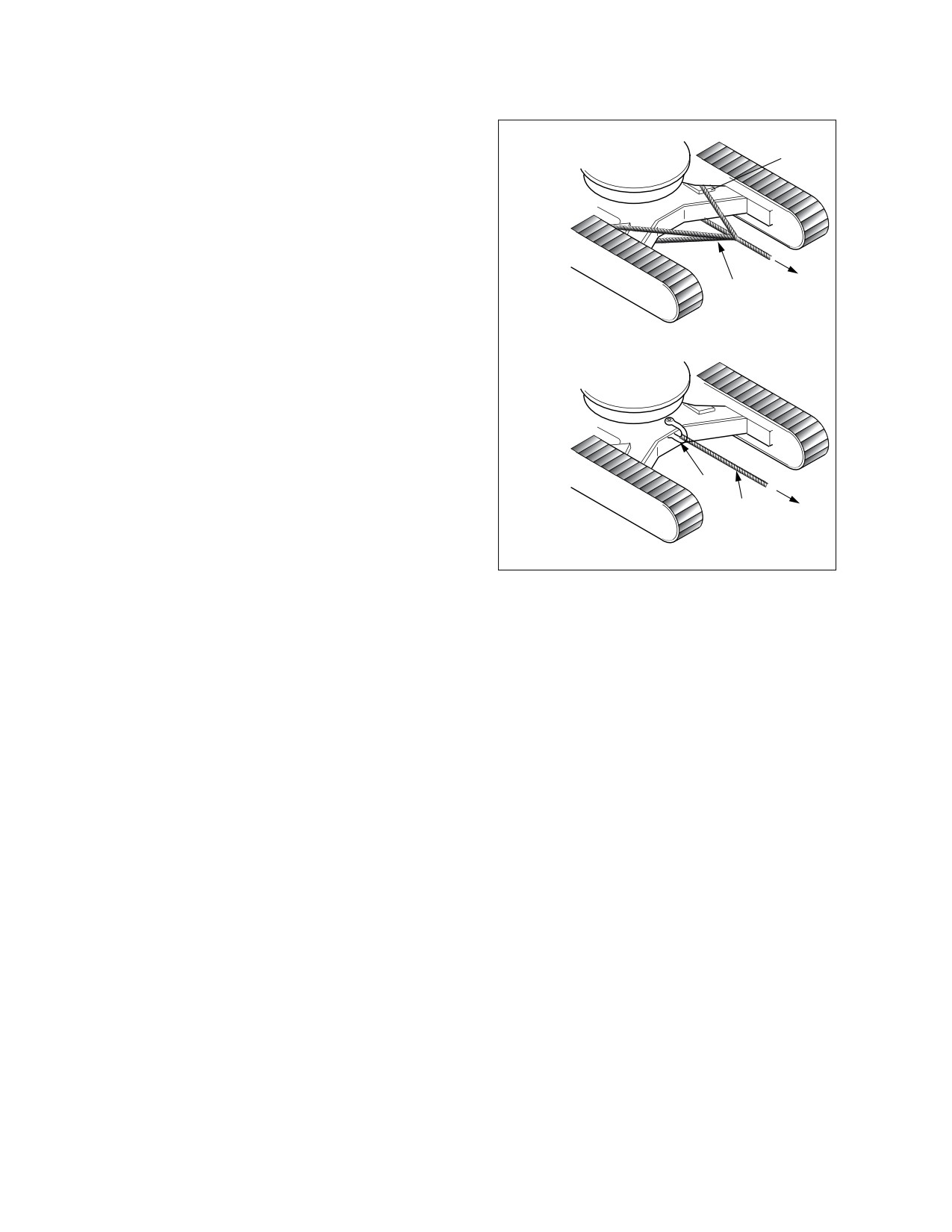
TOWING
PRECAUTIONS WHEN TOWING
If any mistake is made in the method of
selecting or inspecting the towing wire or in the
O
method of towing, it may lead to serious
personal injury. Always do the following;
•
Always use the method of towing
given in this Operation and
Maintenance Manual. Do not use any
other method.
•
Use leather gloves when handling
the wire rope.
•
When carrying out the preparation
work for towing with two or more
X
workers, determine the signals to use
and follow these signals correctly.
•
Always fit the towing rope to the left
and right hooks and secure in
position.
•
If the engine on the problem machine
will not start or there is a failure in the
brake system. always contact your
HAOC910L
Daewoo distributor.
Figure 42
•
Never go between the towing
machine and the towed machine
during the towing operation.
•
It is dangerous to carry out towing on
slopes, so select a place where the
slope is gradual. If there is no place
where the slope is gradual, carry out
operations to reduce the angle of the
slope before starting the towing
operation.
•
When towing a problem machine,
always use a wire rope with a
sufficient towing capacity.
•
Do not use a frayed, kinked rope or a
rope with any loss of diameter.
•
Do not use the light-weight towing
hook for towing another machine.
022-00031E Operation and Maintenance Manual
Safety 1-39
SHIPPING AND TRANSPORTATION
OBEY STATE AND LOCAL OVER-THE-ROAD REGULATIONS
Check state and local restrictions regarding weight, width and length of a load before making any other
preparation for transport.
The hauling vehicle, trailer and load must all be in compliance with local regulations governing the intended
shipping route.
Partial disassembly or tear-down of the excavator may be necessary to meet travel restrictions or particular
conditions at the work site. See the Shop Manual for information on partial disassembly.
Refer to the Transportation and Shipping section of this Operation and Maintenance Manual for information
on loading, unloading and towing.
1-40 Safety
022-00031E Operation and Maintenance Manual
EXCAVATOR RATED LIFT CAPACITY TABLES
WARNING!
All rated lift capacities are based on the machine and the load both remaining level at all times.
DO NOT EXCEED THE RATED LIFT CAPACITY. Lifting loads greater than those shown in the
rated capacity tables can cause catastrophic equipment failure and/or structural collapse of the
machine.
To operate safely the excavator should be on a firm, level and uniformly supporting surface. The operator is
expected to make due allowance for all specific work site and lift-related conditions, and respond to
changes in those conditions that could pose a hazard. The following could all cause hazardous conditions
and accidents or injuries:
•
Soft or uneven ground.
•
Off-level terrain.
•
Side loads.
•
Modifications or poor maintenance of the excavator.
•
Failure to lift squarely over the end or over the side of the machine.
When a load is in the air, the operator must remain alert.
•
Avoid side loads that may be caused by uneven slings, traveling with the load or swinging too
quickly.
•
The load can become unbalanced if the hookline is twisted and starts to rotate. If the surface
area of the load is large enough, wind gusts can create side loads.
•
Keep the bucket hook point directly over the load. Taglines on opposite sides of the load can
help maintain greater stability against side loads and wind gusts.
Avoid traveling with a suspended load. Before swinging (or if required, traveling), bring the load into an arm
position (radius and height) that has a safer weight capacity rating and adequate movement clearance. The
operator and all work site personnel should be thoroughly familiar with safety instructions and procedures
within this Operation and Maintenance Manual.
The following weight loads are in compliance with SAE (J1097) and ISO applicable, recommended
standards for hydraulic excavators performing lifting operation on a firm supporting surface. An asterisk (*)
next to the lift rating indicates rated load does not exceed 87% of hydraulic capacity. All other ratings have
been determined not to exceed 75% of tipping capacity.
DO NOT attempt to lift or hold any load that exceeds rated load capacity at the specified distances (from
the machine’s rotation centerline and height - see "lift radius" and "lift height" in the reference drawing,
Figure 43).
022-00031E Operation and Maintenance Manual
Safety 1-41
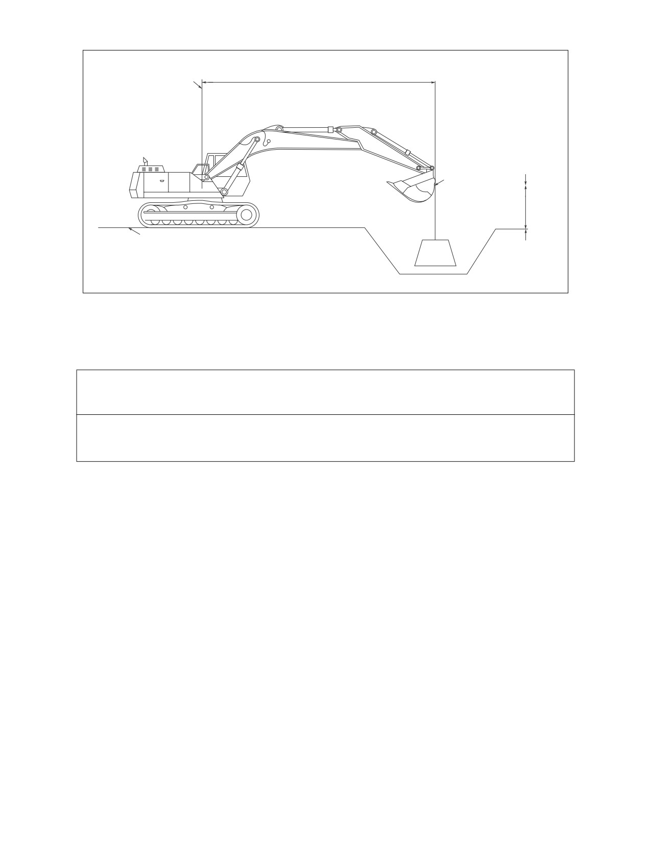
Centerline
of Rotation
Lifting Radius
Lifting
Point
Lifting
Point
Height
Ground Line (Machine Supporting Surface)
AYO0530L
Figure 43
The weight of slings and any auxiliary lifting device (and/or the weight difference of any attachment heavier
than standard configuration) must be deducted from the rated lift capacity to determine allowable net lifting
load. The lift point should be on the back of the bucket, as shown in Figure 43.
IMPORTANT
Select the Digging Mode switch on the Instrument Panel before using the excavator for lifting
work. Engine and hydraulic oil should both be fully warmed up to operating temperature before
starting a lift.
1-42 Safety
022-00031E Operation and Maintenance Manual
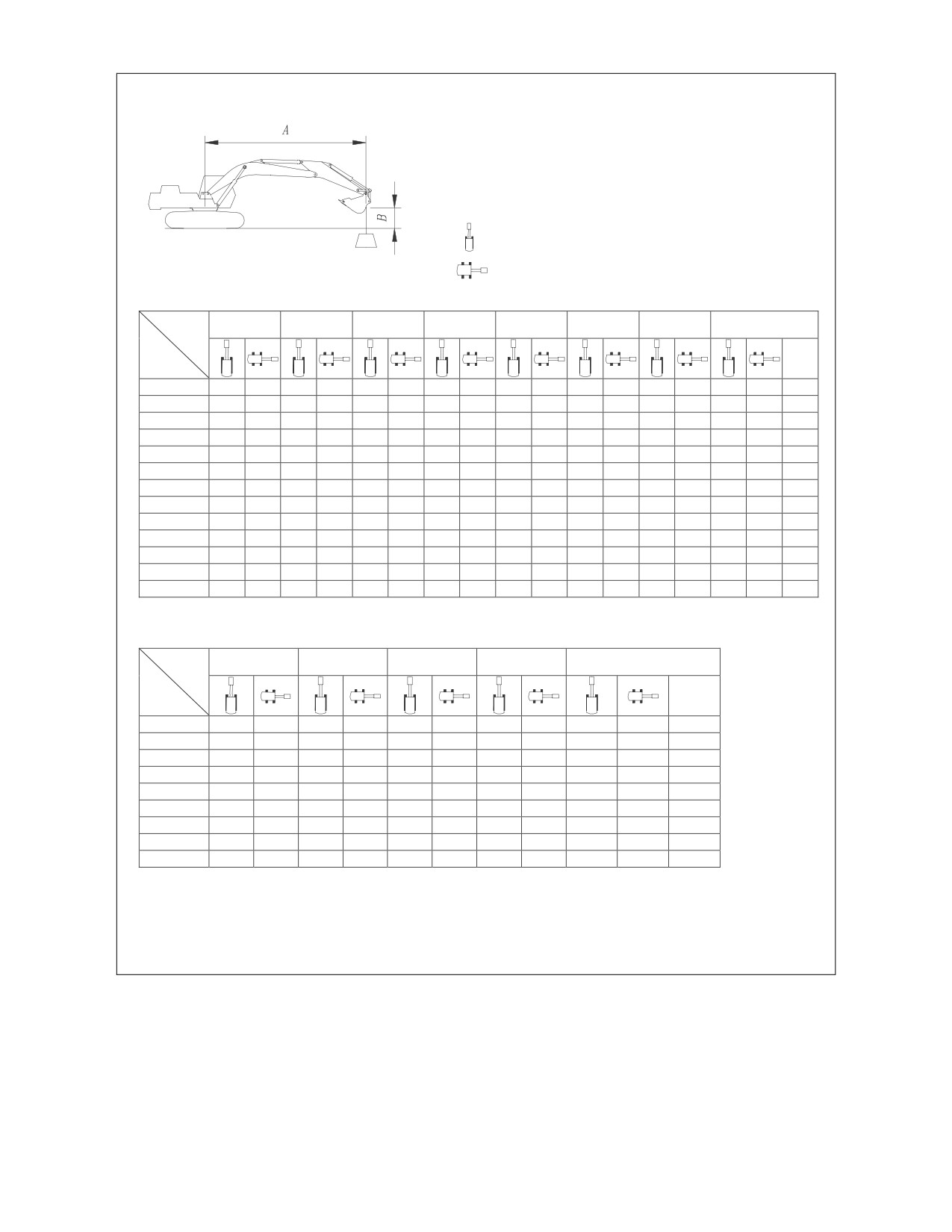
TRACK WIDTH : 3.2m (10' 6") STD TRACK
BOOM
: 5.9m (19' 4")
ARM
: 3.0m (9' 10")
BUCKET
:
SAE 1.1m3
(CECE 0.95m3)
SHOE
: 600mm (24")
UNIT
: 1,000 kg (1,000 lb)
: RATING OVER FRONT
: RATING OVER SIDE OR 360 degree
METRIC
A(m)
2
3
4
5
6
7
8
MAX. REACH
A(m)
B(m)
7
*4.46
*4.46
*3.60
*3.60
7.33
6
*5.03
*5.03
*3.61
*3.61
7.94
5
*5.30
5.01
*4.94
3.99
*3.68
3.67
8.39
4
*6.16
*6.16
*5.71
4.92
*5.43
3.94
*3.81
3.41
8.70
3
*14.32
*14.32
*10.07
*10.07
*8.07
*8.07
*6.93
6.12
*6.21
4.81
*5.74
3.87
*4.00
3.25
8.88
2
*6.75
*6.75
*12.07
11.10
*9.28
7.84
*7.71
5.94
*6.72
4.69
5.79
3.80
*4.26
3.17
8.95
1
*5.86
*5.86
*13.51
10.73
*10.29
7.60
*8.40
5.79
7.04
4.59
5.72
3.74
*4.61
3.16
8.90
0
(GROUND)
*7.18
*7.18
*14.28
10.52
*10.97
7.44
8.86
5.67
6.95
4.51
5.66
3.69
4.94
3.22
8.74
1
*6.21
*6.21
*9.31
*9.31
*14.50
10.43
*11.31
7.35
8.78
5.60
6.90
4.46
5.63
3.66
5.18
3.37
8.46
2
*8.78
*8.78
*12.00
*12.00
*14.28
10.43
*11.29
7.32
8.75
5.57
6.88
4.44
5.63
3.66
5.59
3.63
8.04
3
*11.60
*11.60
*15.36
*15.36
*13.63
10.49
*10.91
7.35
8.77
5.58
6.90
4.46
6.28
4.08
7.46
4
*14.93
*14.93
*15.90
*15.90
*12.47
10.61
*10.05
7.43
*8.19
5.65
*7.04
4.84
6.68
5
*13.29
*13.29
*10.56
*10.56
*8.44
7.58
*7.24
6.38
5.62
FEET
A(ft)
10
15
20
25
MAX. REACH
A(ft)
B(ft)
25
*8.02
*8.02
22.48
20
*9.76
9.66
*7.95
*7.95
25.89
15
*12.62
*12.62
*11.78
9.52
*8.23
7.81
28.01
10
*30.44
*30.44
*19.19
*19.19
*15.01
13.19
*12.95
9.26
*8.80
7.18
29.11
5
*13.84
*13.84
*23.98
19.51
*17.47
12.62
13.69
8.97
*9.73
6.95
29.33
0
(GROUND)
*16.40
*16.40
*26.87
18.80
19.05
12.21
13.45
8.75
10.90
7.10
28.67
-5
*23.98
*23.98
*27.59
18.55
18.83
12.01
13.33
8.65
11.84
7.70
27.08
-10
*34.86
*34.86
*26.28
18.63
18.85
12.03
13.94
9.05
24.36
-15
*31.68
*31.68
*22.37
19.01
*15.89
12.33
*15.81
12.28
20.06
1. RATINGS ARE BASED ON SAE J1097
2. LOAD POINT IS THE HOOK ON THE BACK OF THE BUCKET.
3. * RATED LOADS ARE BASED ON HYDRAULIC CAPACITY.
4. RATED LOADS DO NOT EXCEED 87% OF HYD. CAPACITY OR 75% OF TIPPING CAPACITY.
AYO0020L
022-00031E Operation and Maintenance Manual
Safety 1-43
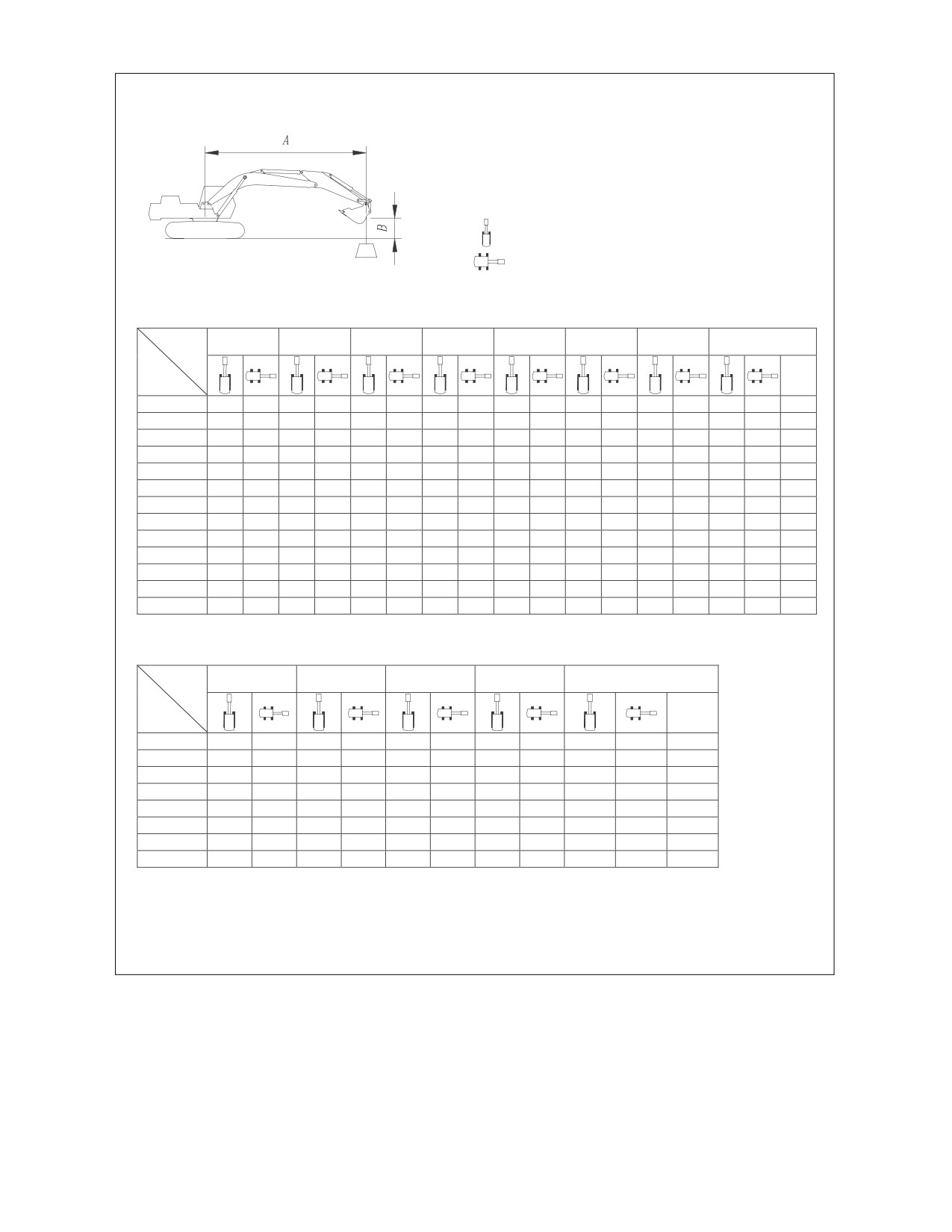
TRACK WIDTH
: 3.2m (10' 6") STD TRACK
BOOM
: 5.9m (20' 6")
ARM
: 2.5m (8' 2")
BUCKET
:
SAE 1.29m3
(CECE1.1m3
)
SHOE
: 600mm (24")
UNIT
: 1,000 kg (1,000 lb)
: RATING OVER FRONT
: RATING OVER SIDE OR 360 degree
METRIC
A(m)
2
3
4
5
6
7
8
MAX. REACH
A(m)
B(m)
7
*4.88
*4.88
6.65
6
*5.46
4.94
*4.91
4.56
7.32
5
*5.96
*5.96
*5.68
4.88
*5.04
4.05
7.80
4
*7.48
*7.48
*6.60
6.16
*6.05
4.80
*5.73
3.83
*5.26
3.73
8.13
3
*11.10
*11.10
*8.67
7.95
*7.32
5.98
*6.50
4.70
5.76
3.78
5.39
3.53
8.33
2
*12.90
10.82
*9.78
7.67
*8.04
5.82
*6.96
4.59
5.70
3.72
5.27
3.43
8.40
1
*14.00
10.53
*10.63
7.47
*8.64
5.68
6.95
4.50
5.64
3.66
5.27
3.42
8.35
0
(GROUND)
*6.84
*6.84
*14.42
10.40
*11.14
7.34
8.78
5.59
6.88
4.44
5.60
3.63
5.41
3.51
8.18
1
*6.88
*6.88
*10.06
*10.06
*14.35
10.37
*11.29
7.28
8.72
5.53
6.84
4.40
5.72
3.70
7.87
2
*10.27
*10.27
*13.71
*13.71
*13.88
10.41
*11.09
7.28
8.71
5.53
6.85
4.40
6.27
4.05
7.42
3
*13.90
*13.90
*16.43
*16.43
*12.97
10.50
*10.48
7.34
*8.58
5.57
7.23
4.65
6.79
4
*18.26
*18.26
*14.36
*14.36
*11.50
10.66
*9.31
7.45
*7.57
5.78
5.92
5
*9.05
*9.05
*7.66
*7.66
4.69
FEET
A(ft)
10
15
20
25
MAX. REACH
A(ft)
B(ft)
20
*10.81
10.2
23.83
15
*13.60
13.42
*12.50
9.26
*11.30
8.58
26.12
10
*20.82
20.19
*15.86
12.89
*13.51
9.04
11.91
7.80
27.30
5
*25.12
19.1
*18.09
12.37
13.50
8.79
11.58
7.54
27.53
0
(GROUND)
*15.67
*15.67
*27.25
18.55
18.86
12.03
13.30
8.61
11.93
7.73
26.83
-5
*26.76
*26.76
*27.23
18.44
18.72
11.90
13.26
8.57
13.16
8.51
25.12
-10
*35.61
*35.61
*25.16
18.62
*18.49
12.00
16.07
10.34
22.16
-15
*27.79
*27.79
*19.98
19.14
*16.89
15.36
17.31
1. RATINGS ARE BASED ON SAE J1097
2. LOAD POINT IS THE HOOK ON THE BACK OF THE BUCKET.
3. * RATED LOADS ARE BASED ON HYDRAULIC CAPACITY.
4. RATED LOADS DO NOT EXCEED 87% OF HYD. CAPACITY OR 75% OF TIPPING CAPACITY.
AYO0030L
1-44 Safety
022-00031E Operation and Maintenance Manual
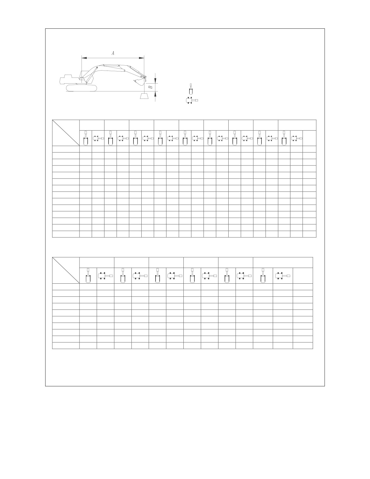
TRACK WIDTH
: 3.2m (10' 6") STD TRACK
BOOM
: 5.9m (20' 6")
ARM
: 3.5m (11' 6")
BUCKET
: SAE
0.93m3(CECE 0.8m3
)
SHOE
: 600mm (24")
UNIT
: 1,000 kg (1,000 lb)
: RATING OVER FRONT
: RATING OVER SIDE OR 360 degree
METRIC
A(m)
2
3
4
5
6
7
8
9
MAX. REACH
A(m)
B(m)
7
*3.09
*3.09
7.88
6
*4.13
4.09
*3.09
*3.09
8.45
5
*4.89
*4.89
*4.84
4.05
*3.14
*3.14
8.87
4
*5.32
4.97
*5.10
3.98
*3.79
3.25
*3.23
3.14
9.16
3
*7.40
*7.40
*6.45
6.18
*5.84
4.85
*5.44
3.90
*4.55
3.20
*3.37
3.00
9.34
2
*10.95
*10.95
*11.12
*11.12
*8.68
7.92
*7.28
5.99
*6.39
4.72
*5.80
3.82
4.81
3.15
*3.56
2.93
9.40
1
*7.29
*7.29
*12.81
10.81
*9.80
7.65
*8.04
5.81
*6.91
4.60
5.72
3.74
4.76
3.10
*3.82
2.91
9.36
0
(GROUND)
*3.85
*3.85
*7.57
*7.57
*13.88
10.53
*10.63
7.45
*8.65
5.67
6.95
4.50
5.65
3.68
4.72
3.07
*4.17
2.96
9.20
1
*5.82
*5.82
*9.03
*9.03
*14.37
10.39
*11.13
7.32
8.76
5.57
6.88
4.44
5.61
3.63
*4.65
3.08
8.93
2
*7.93
*7.93
*11.13
*11.13
*14.38
10.34
*11.28
7.27
8.70
5.52
6.84
4.40
5.59
3.62
5.07
3.29
8.54
3
*10.31
*10.31
*13.85
*13.85
*13.96
10.37
*11.08
7.27
8.70
5.52
6.84
4.40
5.61
3.64
8.00
4
*13.10
*13.10
*16.94
*16.94
*13.06
10.46
*10.46
7.32
*8.56
5.56
6.89
4.45
6.51
4.21
7.28
5
*16.60
*16.60
*14.74
*14.74
*11.53
10.62
*9.26
7.44
*7.42
5.67
*6.85
5.27
6.32
6
*11.38
*11.38
*8.96
*8.96
*6.96
*6.96
4.98
FEET
A(ft)
10
15
20
25
30
MAX. REACH
A(ft)
B(ft)
25
*6.88
*6.88
24.39
20
*10.07
9.82
*6.80
*6.80
27.57
15
*10.97
9.63
*6.99
*6.99
29.56
10
*17.41
*17.41
*13.98
13.32
*12.24
9.33
*8.96
6.87
*7.41
6.63
30.61
5
*19.37
*19.37
*22.54
19.69
*16.62
12.69
*13.67
9.00
10.28
6.72
*8.10
6.42
30.82
0
(GROUND)
*17.29
*17.29
*26.05
18.82
*18.74
12.21
13.44
8.74
*9.94
6.59
*9.19
6.53
30.19
-5
*22.66
*22.66
*27.43
18.43
18.75
11.93
13.27
8.58
10.80
7.00
28.68
-10
*31.42
*31.42
*26.79
18.42
18.70
11.89
13.28
8.59
12.44
8.07
26.14
-15
*34.36
*34.36
*23.82
18.70
*17.32
12.09
*14.87
10.42
22.19
-20
*16.43
*16.43
*15.32
*15.32
15.81
1. RATINGS ARE BASED ON SAE J1097
2. LOAD POINT IS THE HOOK ON THE BACK OF THE BUCKET.
3. * RATED LOADS ARE BASED ON HYDRAULIC CAPACITY.
4. RATED LOADS DO NOT EXCEED 87% OF HYD. CAPACITY OR 75% OF TIPPING CAPACITY.
AYO0040L
022-00031E Operation and Maintenance Manual
Safety 1-45
2OPERATING CONTROLS
The "Operating Controls" section presented here consists of the following groups:
1.
“Component Locations” on page 2-2
2.
“Operator’s Area” on page 2-4
3.
“Operational Controls and Panels” on page 2-5
4.
“Instrument Panel” on page 2-14
5.
“Multifunction Gauge and Graphic Information” on page 2-19
6.
“Mode Selection Buttons” on page 2-23
7.
“Setting Method for Main Menu” on page 2-26
8.
“Heater and Air Conditioner Control Panel” on page 2-30
9.
“Stereo” on page 2-35
10.
“Fuse Boxes” on page 2-42
11.
“Miscellaneous Electrical Devices” on page 2-43
12.
“Seat Adjustment” on page 2-45
13.
“Seat Belt” on page 2-47
14.
“Ceiling Cover” on page 2-48
15.
“Front Windows” on page 2-49
16.
“Door Side Latch” on page 2-52
17.
“Miscellaneous Access Covers and Doors” on page 2-53
18.
“Cab Storage Compartments” on page 2-54
19.
“Ashtray” on page 2-54
21.
“Emergency Glass Breaking Tool” on page 2-55
Each group is explained with a point location drawing or photo and a brief description of each control,
switch, gauge or valve.
Indicator lights work in addition to the gauges on the instrument panel. The operator should monitor
machine pressure on the instrument panel along with indicator lights. These lights will only give the
operator an indication that there is a problem.
WARNING!
Warning lights. When any one or more of the warning lights on the control console, come "ON,"
immediately stop operation and shut down unit. Investigate and correct the problem before
proceeding with operation.
022-00031E Operation and Maintenance Manual
Operating Controls 2-1
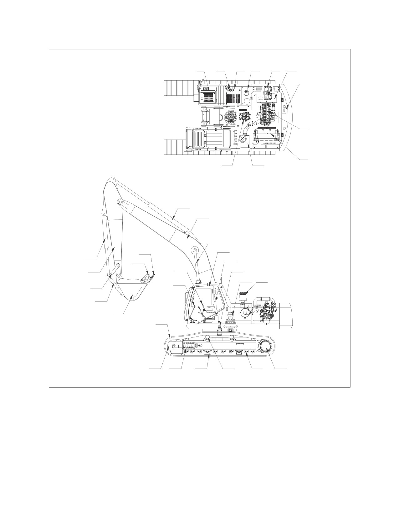
COMPONENT LOCATIONS
1
2
3
4
5
6
7
8
9
11
10
12
13
14
15
29
35
16
30
34
28
17
18
19
27
33
32
31
26
25
24
23
22
21
20
AYO0050L
Figure 1
2-2 Operating Controls
022-00031E Operation and Maintenance Manual
1.
BATTERY
19. PRECLEANER
2.
FUEL TANK FILL CAP
20. TRAVEL MOTOR
3.
FUEL TANK
21. LOWER ROLLER
4.
HYDRAULIC OIL TANK
22. UPPER ROLLER
5.
PUMPS
23. TRACK GUIDE
6.
MUFFLER
24. TRACK ADJUSTER
7.
COUNTERWEIGHT
25. IDLER
8.
ENGINE
26. TRACK LINK AND SHOE
9.
RADIATOR AND OIL COOLER
27. TRAVEL LEVER
10.
AIR CLEANER
28. WORK LEVER (JOYSTICK) CONTROLS
11.
CONTROL VALVES
29. TOOTH POINT
12.
ARM CYLINDER
30. SIDE CUTTER
13.
BOOM
31. BUCKET
14.
BOOM CYLINDER
32. PUSH LINK
15.
CAB
33. GUIDE LINK
16.
SEAT
34. ARM
17.
CENTER JOINT
35. BUCKET CYLINDER
18.
SWING MOTOR
022-00031E Operation and Maintenance Manual
Operating Controls 2-3
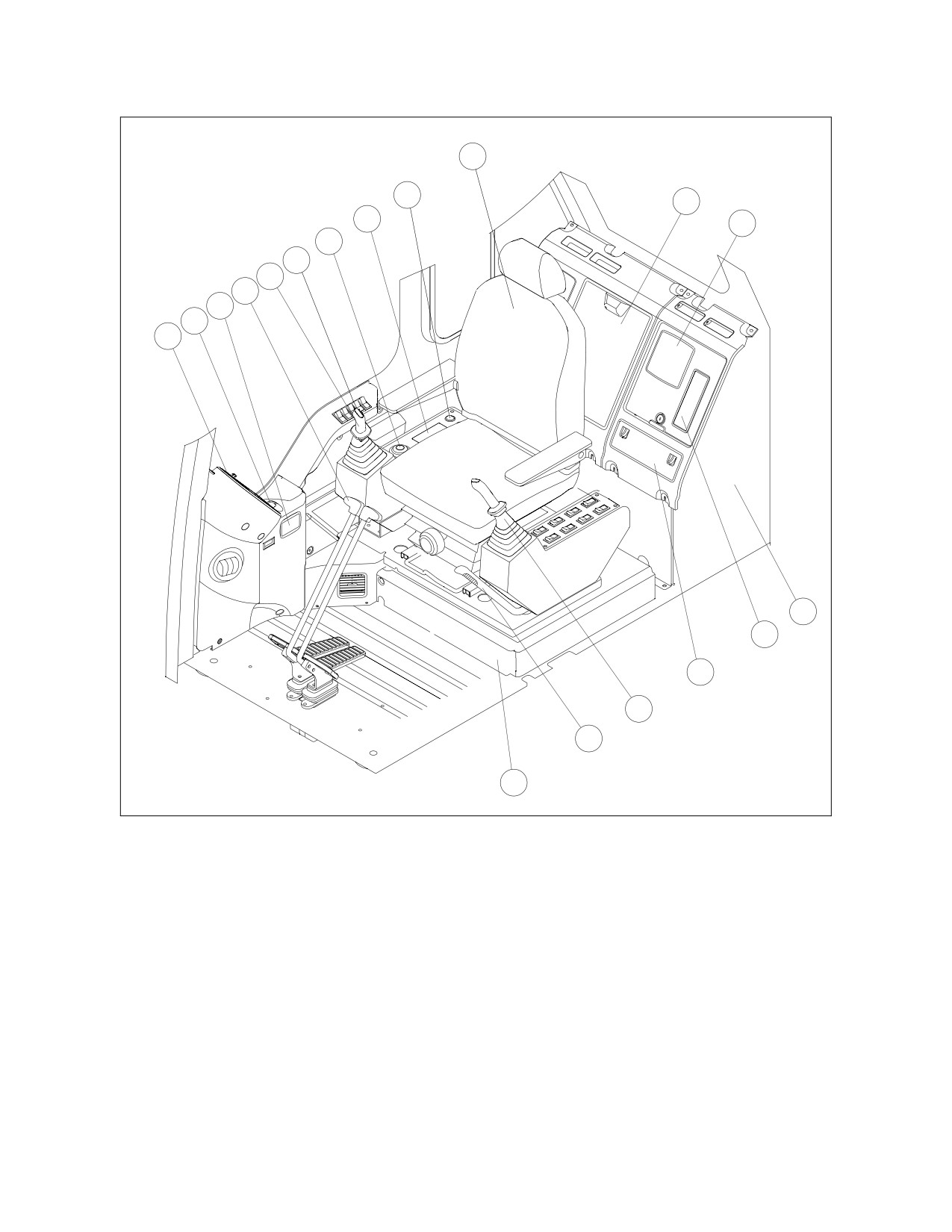
OPERATOR’S AREA
10
9
11
8
12
7
6
5
4
3
2
1
13
14
15
16
17
18
ARO0681L
Figure 2
1.
INSTRUMENT PANEL
10. SEAT
2.
CIGAR LIGHTER
11. STORAGE COMPARTMENT
3.
ASHTRAY
12. SPEAKERS
4.
TRAVEL LEVERS
13. HEATER AND AIR CONDITIONER UNIT
5.
RIGHT HAND WORK LEVER (JOYSTICK)
14. STEREO
6.
SWITCH PANEL
15. FUSE BOX
7.
ENGINE SPEED CONTROL DIAL
16. LEFT HAND WORK LEVER (JOYSTICK)
8.
HEATER AND AIR CONDITIONER
17. SAFETY LEVER
CONTROL PANEL
18. ELECTRIC BOX
9.
STARTER SWITCH
2-4 Operating Controls
022-00031E Operation and Maintenance Manual
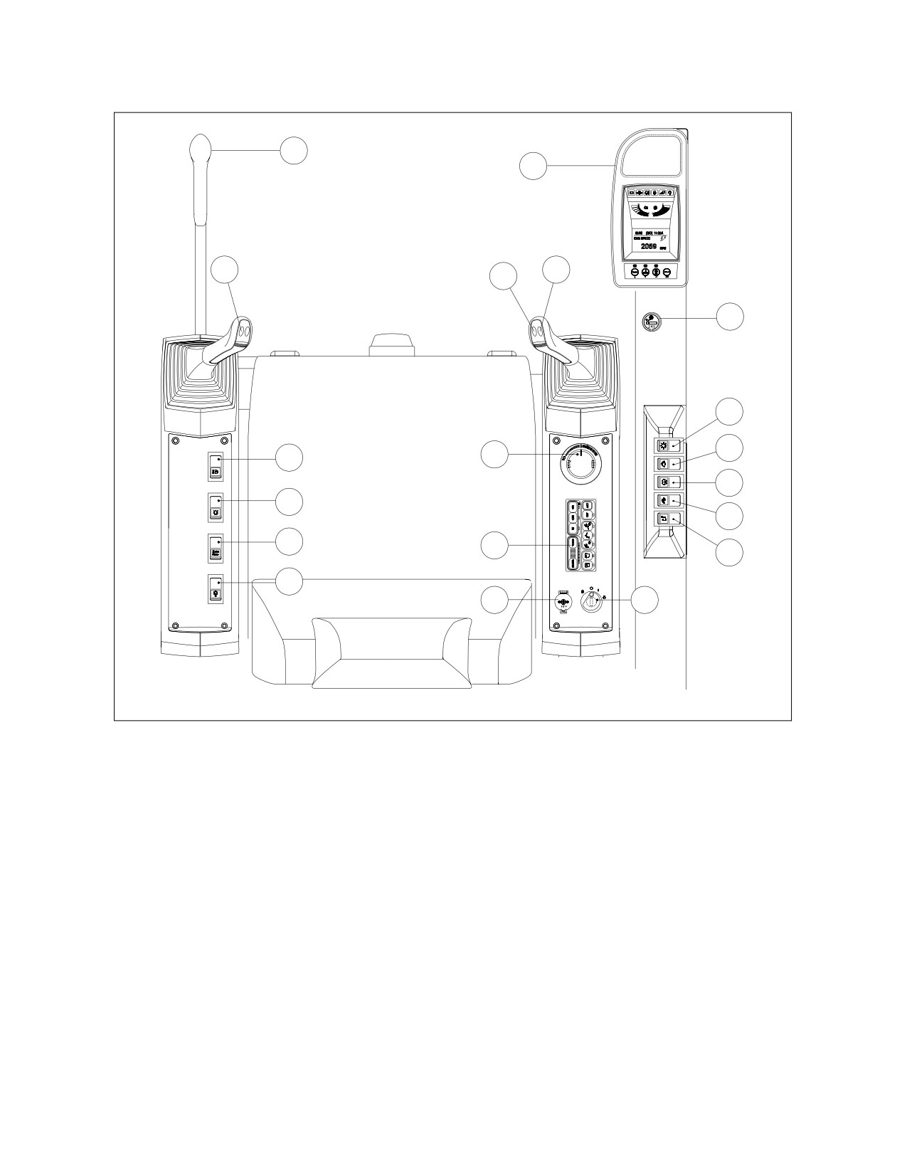
OPERATIONAL CONTROLS AND PANELS
19
18
15
16
17
13
3
4
2
8
5
9
6
10
12
7
11
14
1
ARO0020L
Figure 3
1.
STARTER SWITCH
11. OVERLOAD WARNING SWITCH
2.
ENGINE SPEED CONTROL DIAL
(OPTIONAL)
3.
LIGHT SWITCH
12.
HEATER AND AIR CONDITIONER
4.
WIPER SWITCH
CONTROL PANEL (See page 2-30)
5.
WINDSHIELD WASHER SWITCH
13. CIGAR LIGHTER
(OPTIONAL)
14. POWER SOCKET FOR 12 VOLT
6.
TRAVEL SPEED SELECTION SWITCH
15. HORN SWITCH
7.
STEREO ON/OFF SWITCH
16. BOOSTER SWITCH
8.
CAB WORK LIGHT SWITCH (OPTIONAL)
17. BREAKER SWITCH
9.
WARNING LIGHT SWITCH (OPTIONAL)
18. INSTRUMENT PANEL (See page 2-14)
10.
TRAVEL/SWING ALARM SWITCH
19. SAFETY LEVER (See page 3-14)
(OPTIONAL)
022-00031E Operation and Maintenance Manual
Operating Controls 2-5
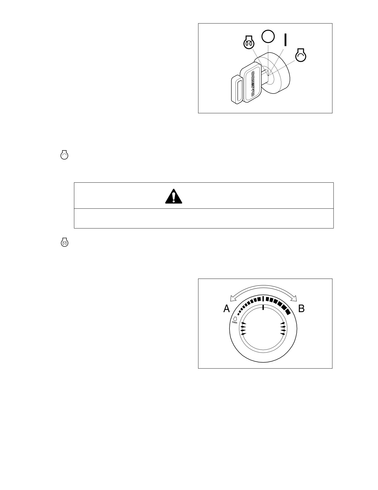
1.
STARTER SWITCH
A four-position starter switch is used to
start or shut down engine for equipment
operation.
O. Turning the switch to this position
turns the engine "OFF" along with its
electrical system. In this position the
engine is "OFF" but the interior cab
light and fuel tank transfer pump (if
equipped) are functional.
I.
Turning the switch to this position
HAOC340L
turns the engine electrical system
Figure 4
"ON." The charge indicator light and
the oil pressure indicator light should
be "ON" at this time.
. Moving switch to this position will crank engine. When engine starts, release key and allow it to
return to "I" (ON) position. Do not operate the starter switch for more than 15 seconds at a time.
This will help prevent damage to starter.
WARNING!
DO NOT USE STARTING FLUIDS. The preheat system could cause the starting fluid to
explode.
. Preheat position. Used to aid engine starting in cold weather. When key is in this position,
engine preheater is operating. When preheat cycle indicator light turns "ON" engine preheat
cycle is complete. Immediately turn key to crank position and start engine.
2.
ENGINE SPEED CONTROL DIAL
The engine speed is controlled by the dial.
Rotating it clockwise increases engine
speed
(rpm) and counterclockwise
decreases engine speed.
A Low idle (Lowest engine speed)
B High idle (Highest engine speed)
NOTE: The auto idle system will
automatically reduce engine
speed
to
idle
speed
HAOA690L
approximately 4 seconds after
Figure 5
all of the control levers are in
the neutral position. This
system is designed to reduce
fuel consumption and noise.
See
“3. Auto Idle Selection
Button” on page 2-24.
2-6 Operating Controls
022-00031E Operation and Maintenance Manual
3.
LIGHT SWITCH
This switch is used to turn on the lights.
O. In this position, all lights are "OFF."
I.
In this position, all illumination lights
O
of the instrument panel and the
I
control switches are turned "ON."
II
II.
In this position, all illumination lights,
work lights and headlights are turned
"ON."
AQO0080L
Figure 6
CAUTION!
Do not leave instrument panel or
headlights "ON" when the engine is
not running. Leaving lights "ON" with
the engine shut down will discharge
batteries.
4.
WIPER SWITCH
O. In this position, windshield wiper is
"OFF."
I.
In this position, windshield wiper runs
O
at constant speed.
I
II.
In this position, windshield wiper runs
on approximately five seconds
II
intermittent cycle.
NOTE: Operating wiper without washer
fluid or when there is sand or
HAOA730L
dirt present will damage the
Figure 7
window and/or wiper.
022-00031E Operation and Maintenance Manual
Operating Controls 2-7
5.
WINDSHIELD WASHER SWITCH
While the windshield wiper is running,
depress the washer switch to spray
windshield washer fluid onto the
windshield. Use only the proper windshield
O
washer fluid in the system.
O. In this position, the washer is "OFF."
I
I.
In this position, the windshield
washer sprays fluid. When released
the switch returns to the "O" (OFF)
position.
HAOA740L
Figure 8
NOTE: Do not operate the windshield
washer without any fluid. If you
operate it in spite of running out
of fluid, the washer motor may
be damaged. Check level in
washer tank, and add fluid as
required.
NOTE: If you use soapy water or
synthetic detergent instead of
window cleaning fluid, the wiper
blade or painted surfaces may
be damaged. Use standard
window cleaning fluid: SSK703
6.
TRAVEL SPEED SELECTION SWITCH
WARNING!
O
Do not operate the Travel Speed
I
Switch when unit is in motion.
Temporary loss of control could
II
result.
This switch activates the automatic speed
range for travel.
ARO0030L
Figure 9
O. In this position, "LOW" travel speed is
selected.
I.
In this position, "HIGH" travel speed
is selected.
II.
In this position, "AUTOMATIC" travel
speed is selected. The travel speed
automatically changes from low to
high range depending on engine
speed and travel motor load.
2-8 Operating Controls
022-00031E Operation and Maintenance Manual
7.
STEREO ON/OFF SWITCH
This switch is used to turn the main power
supply from the fuse box to the stereo
"ON" or "OFF."
Main power to the stereo will only be
O
turned "ON" when the starter switch is
turned to the "I"
(ON) position, and the
stereo switch is set to the "I" (ON) position.
I
When this is done, the normal stereo “1.
Power/Volume Control Knob” on page 2-36
can be used to control the stereo.
ARO0040L
If either the starter switch or the stereo on/
Figure 10
off switch (Figure 10) is turned "OFF" the
stereo will be turned "OFF" despite the
actual “1. Power/Volume Control Knob” on
page 2-36.
8.
CAB WORK LIGHT SWITCH
(OPTIONAL)
This switch is used to control the cab work
lights, if unit is equipped with them.
O. In this position, all cab work lights are
O
turned "OFF."
I
I.
In this position, the front cab work
lights on the front top of cab will turn
II
"ON."
II.
In this position, the front cab work
ARO0050L
lights on the front top of cab and rear
Figure 11
cab work lights on rear top of cab will
turn "ON."
9.
WARNING LIGHT SWITCH (OPTIONAL)
If unit is equipped with a warning light,
push this switch to activate it.
O. In this position, the warning light is
O
turned "OFF."
I.
In this position, the warning light
turns "ON" and will start flashing.
I
HAOA750L
Figure 12
022-00031E Operation and Maintenance Manual
Operating Controls 2-9
10.
TRAVEL/SWING ALARM SWITCH
(OPTIONAL)
If unit is equipped with an alarm buzzer for
travel/swing alarm, push this switch to
activate the alarm whenever swinging or
O
traveling.
I
O. In this position, the travel/swing
alarm system is turned "OFF."
II
I.
In this position, only the travel alarm
will sound, when the machine is
moving.
ARO0060L
Figure 13
II.
In this position, the alarm will sound
while swinging, and traveling, if
equipped with a swing alarm device.
NOTE: If only equipped with a travel
alarm device, the alarm will not
sound while swinging although
the switch is turned to the "II"
position.
11.
OVERLOAD WARNING SWITCH
(OPTIONAL)
If unit is equipped with an overload
warning device, push this switch to activate
it.
O
O. In this position, the overload warning
device is turned "OFF."
I
I.
In this position, when the lifting load
is reached to limit, a warning light on
the instrument panel will turn "ON"
and a warning buzzer will sound.
ARO0070L
Figure 14
WARNING!
To prevent injury, do not exceed the
rated load capacity of the machine. If
the machine is not on level ground,
load capacities will vary. There may
be local government regulations
about the use of excavators for the
lifting of heavy objects.
Please observe those regulations.
2-10 Operating Controls
022-00031E Operation and Maintenance Manual
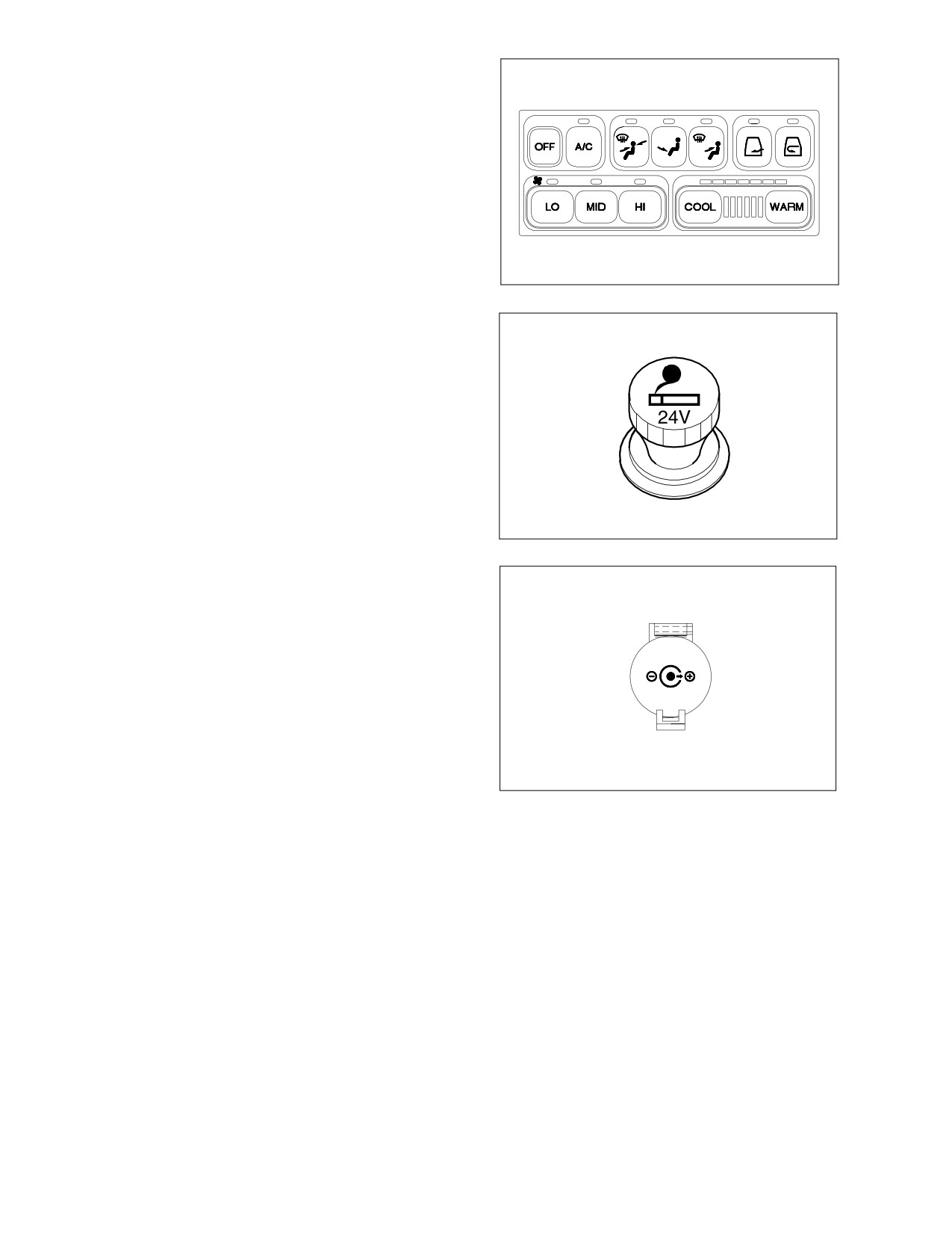
12. HEATER AND AIR CONDITIONER
CONTROL PANEL
Used to control air-conditioner and heater
in operator’s compartment. Refer to
“Heater and Air Conditioner Control Panel”
on page 2-30 for more details.
ARO0080L
Figure 15
13.
CIGAR LIGHTER
Push the lighter all the way into the socket
and release your hand. After pushing it in,
it will be ejected when it is heated. If it
does not eject after a short time, pull it out
and have it serviced.
NOTE: This cigar lighter is for 24V only.
Never connect a 12V electrical
device to the lighter.
HAOA780L
Figure 16
14.
POWER SOCKET FOR 12 VOLT
This is a power socket for only 12V DC
devices.
This socket can be used for charging a
cellular phone or powering a small 12V DC
electrical device.
12 V
Open the cap when using it.
NOTE: This socket is designed for
small
electrical
capacity
devices. Do not use this socket
ARO0090L
for large electrical capacity
Figure 17
devices. Thus damage can be
avoided.
022-00031E Operation and Maintenance Manual
Operating Controls 2-11
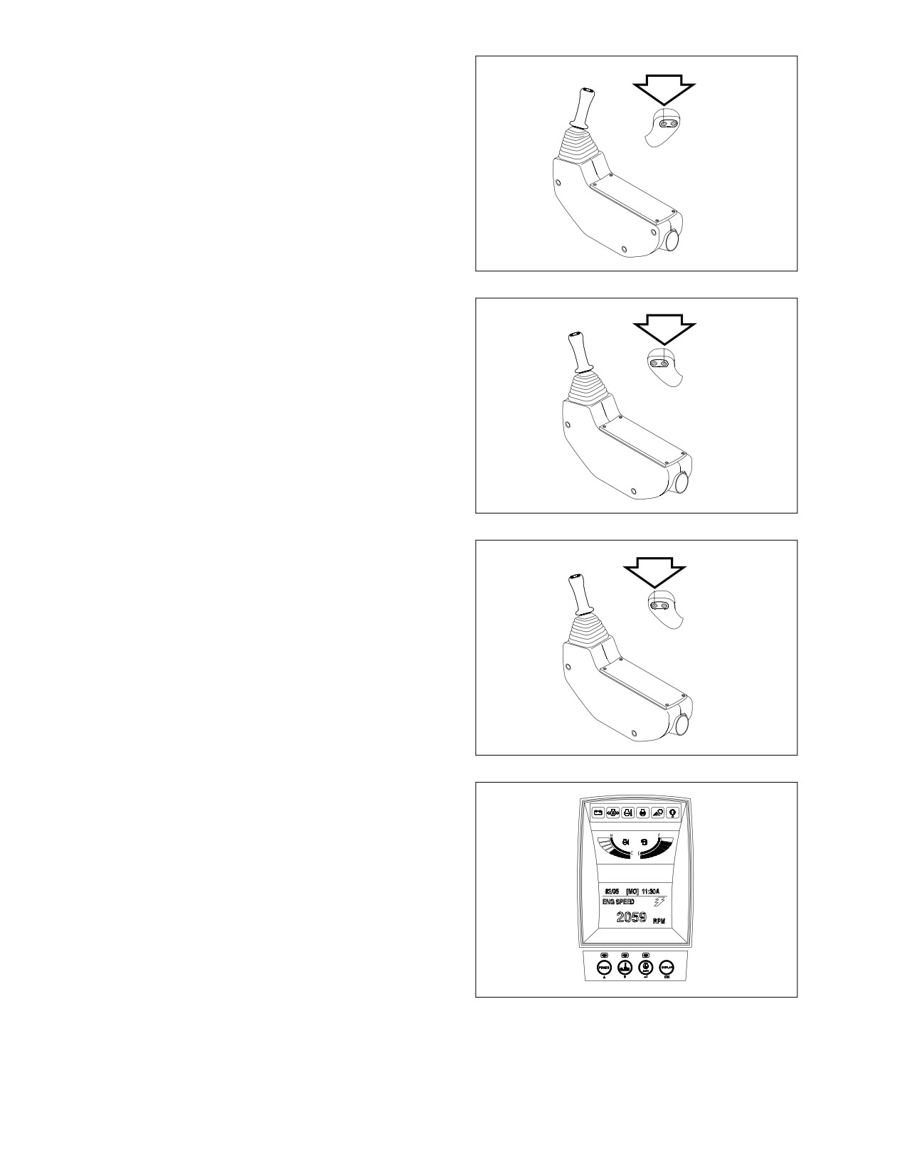
15. HORN SWITCH (LEFT HAND WORK
LEVER (JOYSTICK))
Press the left side button on the top of the
left hand work lever
(joystick) to sound
horn.
HAAD4250
Figure 18
16. BOOSTER SWITCH (RIGHT HAND
WORK LEVER (JOYSTICK))
Press the right side button on the top of
the right hand work lever (joystick) to boost
the hydraulic pressure. Refer to the “Boost
Mode” on page 3-24.
ARO0110L
Figure 19
17. BREAKER SWITCH (RIGHT HAND
WORK LEVER (JOYSTICK))
Press the left side button on the top of the
right hand work lever (joystick) to activate
the hydraulic breaker.
Release the left side button on the top of
the right hand work lever
(joystick) to
deactivate the hydraulic breaker.
ARO0120L
Figure 20
18. INSTRUMENT PANEL
See “Instrument Panel” on page 2-14.
ARO0130L
Figure 21
2-12 Operating Controls
022-00031E Operation and Maintenance Manual
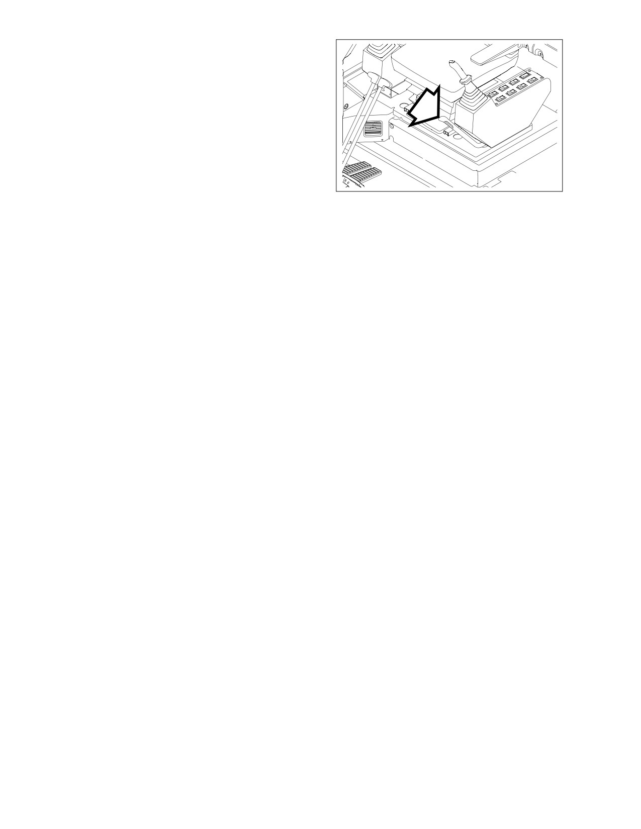
19. SAFETY LEVER
See “Safety Lever” on page 3-14.
HAAD3770
Figure 22
022-00031E Operation and Maintenance Manual
Operating Controls 2-13
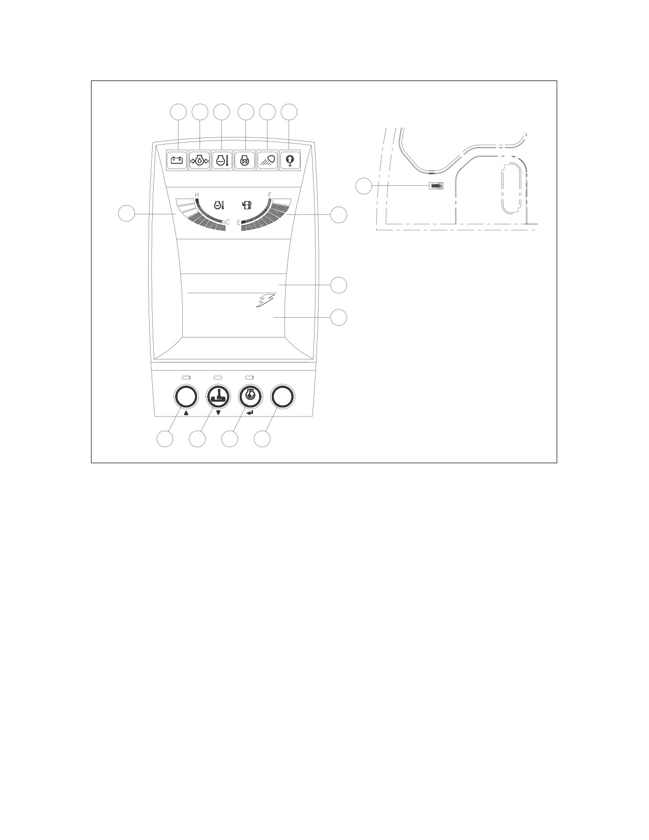
INSTRUMENT PANEL
6
7
8
9
10
11
5
1
2
02/05
[MO] 11:30A
4
ENG SPEED
3
2059
RPM
POWER
DISPLAY
AUTO
ESC
12
13
14
15
ARO0010L
Figure 23
1.
ENGINE COOLANT TEMPERATURE
9.
PREHEATING COMPLETION LIGHT
GAUGE
10.
WORK LIGHT INDICATOR LIGHT
2.
FUEL GAUGE
11.
OVERLOAD WARNING LIGHT
3.
MULTIFUNCTION GAUGE AND GRAPHIC
(OPTIONAL)
INFORMATION AREA (See page 2-19)
12. POWER MODE SELECTION BUTTON
4.
DIGITAL CLOCK
(See page 2-23)
5.
HOUR METER
13. WORK MODE SELECTION BUTTON (See
6.
CHARGE WARNING LIGHT
page 2-24)
7.
ENGINE OIL PRESSURE WARNING
14. AUTO IDLE SELECTION BUTTON (See
LIGHT
page 2-24)
8.
COOLANT TEMPERATURE WARNING
15. DISPLAY SELECTION BUTTON (See page
LIGHT
2-25)
2-14 Operating Controls
022-00031E Operation and Maintenance Manual
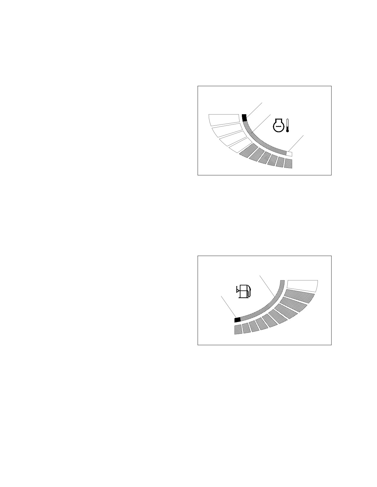
FUNCTIONAL CHECK
When the engine starter switch is turned to the "I" (ON) position, all bands of gauges, indicator lights of
switches/buttons and indicator/warning lights will turn "ON" and the alarm buzzer will sound for about 2
seconds.
During this time, a moving excavator will appear on the digital clock and graphic information area (3 and 4,
Figure 23).
1.
ENGINE COOLANT TEMPERATURE
GAUGE
RED
The colored bands indicate the
H
temperature of the engine coolant.
GREEN
WHITE ZONE - Indicates temperature is
lower than the normal operating
WHITE
temperature.
GREEN ZONE - Indicates temperature is
within the normal operating range.
C
RED ZONE - Indicates temperature is too
ARO0140L
high.
Figure 24
During operation, the bands must be in the
green zone.
If the band in the red zone starts to blink, a warning buzzer will sound and the engine speed will be
automatically reduced. At this time, allow the engine to run at low idle speed until the temperature
gauge registers in the green zone again. When the green zone is reached, shut down engine. Check
the coolant level, for a loose fan belt, inspect for debris around radiator and so on.
When the temperature reaches the normal range, the engine speed will automatically recover.
2.
FUEL GAUGE
Shows remaining fuel quantity in tank.
GREEN
F
GREEN ZONE - Indicates a normal fuel
quantity.
RED
RED ZONE - Indicates that the fuel level is
low.
If the band in the red zone starts to blink,
E
add fuel immediately.
Check the fuel level on smooth, level
ground.
ARO0150L
Figure 25
022-00031E Operation and Maintenance Manual
Operating Controls 2-15
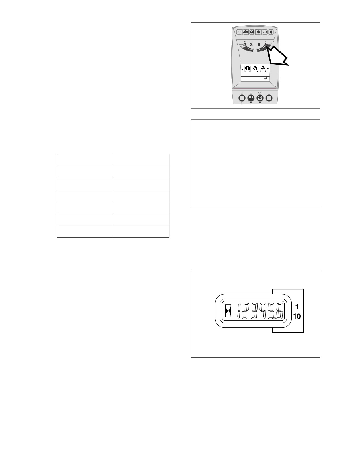
3.
MULTIFUNCTION GAUGE AND
GRAPHIC INFORMATION AREA
See
“Multifunction Gauge and Graphic
Information” on page 2-19.
1.Fuel Filter
Hrs: 0232 Reset:
POWER
DISPLAY
AUTO
ESC
HAAD3781
Figure 26
4.
DIGITAL CLOCK
As a digital clock, it indicates the current
time. The displayed contents are as
follows.
Display
Description
MM/DD [W] HH:mm A
MM
Month
DD
Date
W
Day
ARO0350L
HH
Hour
Figure 27
mm
Minute
A (P)
AM (PM)
Refer to the
“Setting Method for Main
Menu” on page 2-26" for time setting.
5.
HOUR METER
The hour meter is used to indicate the total
number of running hours on the engine.
The meter will flash every 4 seconds when
the engine is running to indicate that it is
functioning properly.
HAOA600L
Figure 28
2-16 Operating Controls
022-00031E Operation and Maintenance Manual
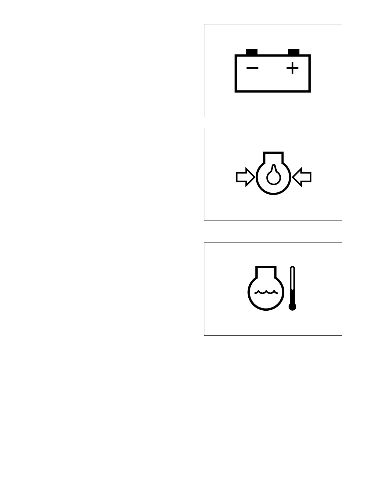
6.
CHARGE WARNING LIGHT
This indicator light will turn "ON" when the
engine starter switch is turned "ON," and
should go "OFF" after the engine starts. If
it does not turn "OFF," shut the engine
down immediately and determine the
cause of the problem.
HAOA610L
Figure 29
7.
ENGINE OIL PRESSURE WARNING
LIGHT
This indicator light will turn "ON" when the
engine starter switch is turned "ON," and
should go "OFF" after the engine starts.
For example, if the engine oil pressure
becomes too low, the light will turn "ON"
and a warning buzzer will sound. If this
happens, shut the engine down
immediately and determine the cause of
the problem. If you continue to work when
this light is "ON," it will result in serious
HAOA620L
engine damage.
Figure 30
8.
COOLANT TEMPERATURE WARNING
LIGHT
If engine coolant overheats, this light will
turns "ON" and an alarm will sound. If light
turns "ON," reduce engine speed until
coolant temperature drops. Do not turn
engine "OFF" because this will cause
coolant temperature to rise and may cause
engine to siege due to heat surge.
NOTE: Check the coolant temperature
gauge. If the band in the red
HAOD350L
zone starts to blink, a warning
Figure 31
buzzer will sound and the
engine
speed
will
be
automatically reduced. At this time, allow the engine to run at low idle speed until the
temperature gauge registers in the green zone again. When the green zone is reached,
shut down engine. Check the coolant level, for a loose fan belt, inspect for debris around
radiator and so on.
When the temperature reaches the normal range, the engine speed will automatically
recover.
022-00031E Operation and Maintenance Manual
Operating Controls 2-17
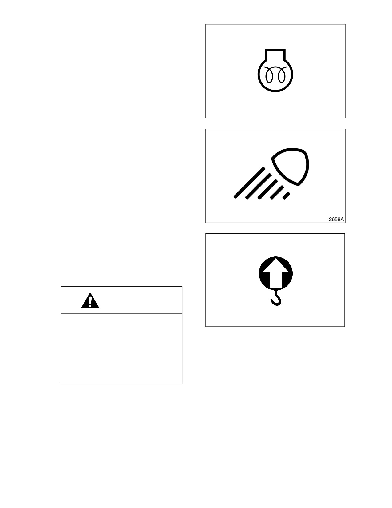
9.
PREHEATING COMPLETION LIGHT
This light indicates that the engine preheat
function has been completed.
HAOA639L
Figure 32
10. WORK LIGHT INDICATOR LIGHT
The indicator light indicates that the work
lights are turned on.
Figure 33
11. OVERLOAD WARNING LIGHT
(OPTIONAL)
On machine with an overload warning
device, this indicator light will turn "ON"
and a warning buzzer sounds when the
load limit has been reached.
WARNING!
If this indicator light turns "ON"
ARO0220L
during the lifting operation, reduce
Figure 34
the load immediately.
If you continue to work when this
light is "ON" the machine can be
overturned or damage to hydraulic
components and structural parts
could occur.
2-18 Operating Controls
022-00031E Operation and Maintenance Manual
//////////////////////////////////////////