Doosan DX700LC. Operation and Maintenance Manual (2010) - page 5

MAINTENANCE IN SPECIAL
CONDITIONS
NOTE: See
“Operation Under Unusual Conditions” on
page 3-42 for other recommendations.
Conditions
Maintenance Required
Operating in mud, water or rain.
Perform a walk around inspection to check for any loose
fittings, obvious damage to the machine or any fluid leakage.
After completing operations, clean mud, rocks or debris from
the machine. Inspect for damage, cracked welds or loosened
parts.
Perform all daily lubrication and service.
If the operations were in salt water or other corrosive materials,
make sure to flush the affected equipment with fresh water.
Operating in an extremely dusty or hot
Clean the air intake filters on a more frequent basis.
environment.
Clean the radiator and oil cooler fins to remove embedded dirt
and dust.
Clean the fuel system intake strainer and fuel filter more
frequently.
Inspect and clean as required the starter and alternator.
Operating in rocky terrain.
Check the undercarriage and track assemblies for damage or
excessive wear.
Inspect for loose or damaged fittings or bolts.
Relax track tension.
On a more frequent basis, inspect the front end attachments for
damage or excessive wear.
Install a top guard and front guard as required for protection
against falling rock.
Operating in extreme cold.
Use the proper fuel for the temperature conditions.
Using a hydrometer, check the antifreeze to make sure that it is
providing the proper cold weather freeze protection.
Verify the condition of the batteries. In extremely cold weather
remove the batteries at night and store them in a warmer area.
Remove mud buildup as soon as possible to prevent it from
freezing to the undercarriage and causing damage.
Inspection, Maintenance and Adjustment
OP001123
4-93
Inspection, Maintenance and Adjustment
OP001123
4-94
OP001124
5Transportation
Obey all local, state or federal regulations for transportation of
excavator. If unsure of regulations check with local authorities.
Check intended route for road width, overhead clearances,
weight restrictions, and traffic control regulations. Special
approval or permits may be required.
DISASSEMBLY AND ASSEMBLY
BEFORE AND AFTER
TRANSPORTATION
When necessary, machine should have counterweight and front
attachment removed for transport between locations. The tracks
should be retracted before removing counterweight and front
attachment.
If equipped, removable counterweight may also have to be
removed.
NOTE: Obey all local, state or federal regulations for
transportation of excavator. If unsure of regulations
check with local authorities.
Check intended route for road width, overhead
clearances, weight restrictions, and traffic control
regulations. Special approval or permits may be
required.
When doing this operation, make sure that it is done on solid
level ground, with adequate room for maneuvering all equipment
and keeping personnel at a safe distance when required.
WARNING
If engine must be run while performing maintenance, use
extreme care. Always have one person in cabin at all times.
Never leave cabin with engine running.
Personnel and Equipment
1.
Disassembly and Reassembly: 3 persons
2.
Crane Operator: 1 person
3.
Crane Equipment: 1 machine
Transportation
OP001124
5-1
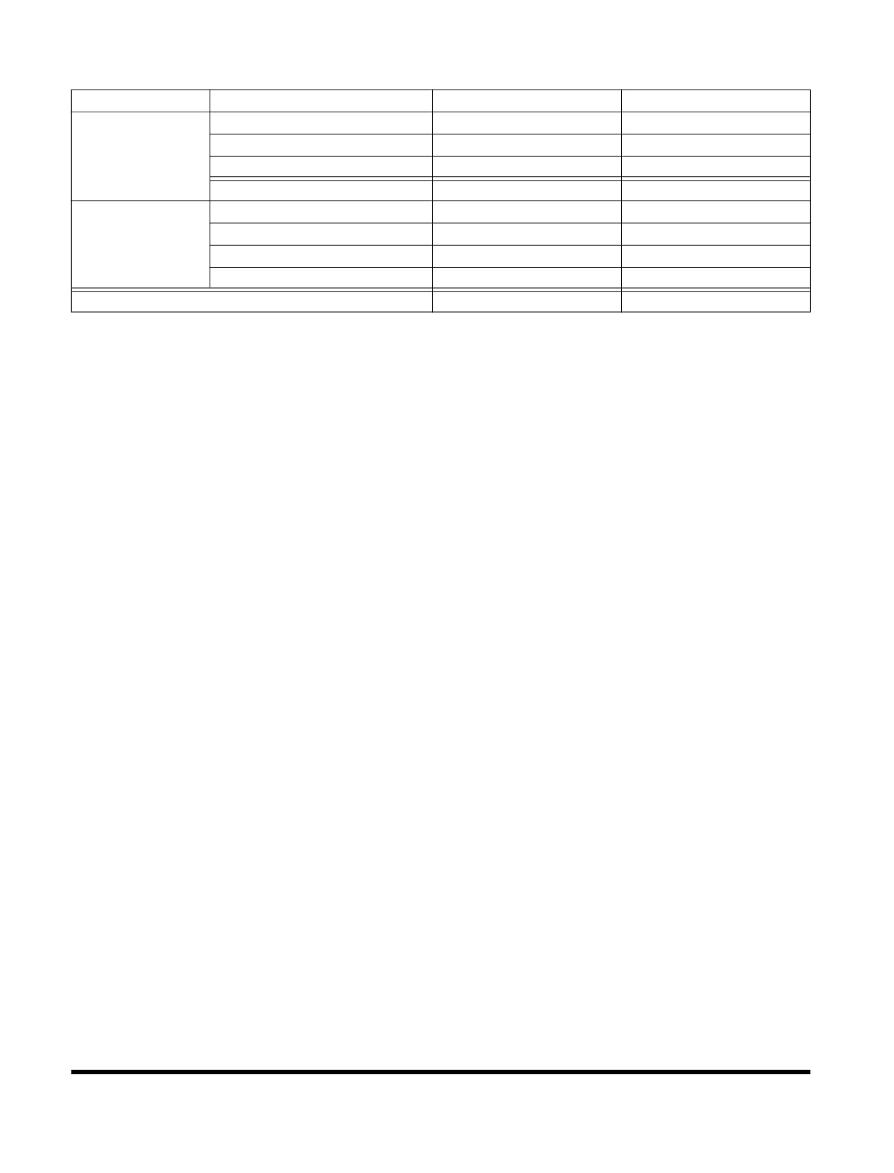
Time Required
Work
Procedures
Time Required
Equipment to be Used
Counterweight Disassembly
25 min
Crane
Disassembly and
Track Side Frame Disassembly
45 min
Crane
Loading on
Front Disassembly
1 h 20 min
Crane
Carrier
Sub Total
2 h 30 min
Front Assembly
2 h
Crane
Track Side Frame Assembly
1 h
Crane
Reassembly
Counterweight Assembly
1 h
Crane
Sub Total
4 h
Total Sum
6 h 30 min
Transportation
OP001124
5-2
Track Frame Extension and Retraction
CAUTION
Be sure to clean all off all dirt and mud from tread surface of
center frame, and on side frames; otherwise, it may cause
bolts to loosen.
Operate machine with side frames retracted only when
loading and unloading machine, or during driving for
loading and unloading.
Do not retract side frames for excavating or during normal
driving and operation. If machine is operated with either
side frame retracted, or even one side frame retracted,
during operation, cabin/machine will become unstable. This
can cause damage to, center frame, side frames, bolts, etc.
There are only six bolts holding side frame at each location
instead of nine.
Operation with side frame retracted could even result in a
tip over, serious injury and death.
Track Width Adjustment
The DX700LC has a variable track width device that allows
tracks to be retracted 300 mm on each side of machine.
The retraction device should only be used during transportation.
During machine operation at a work site, track width device
should be adjusted to have widest track width. If not, stability of
machine will be greatly reduced, which could result in fatal
accidents and damage.
Frame Retraction
1.
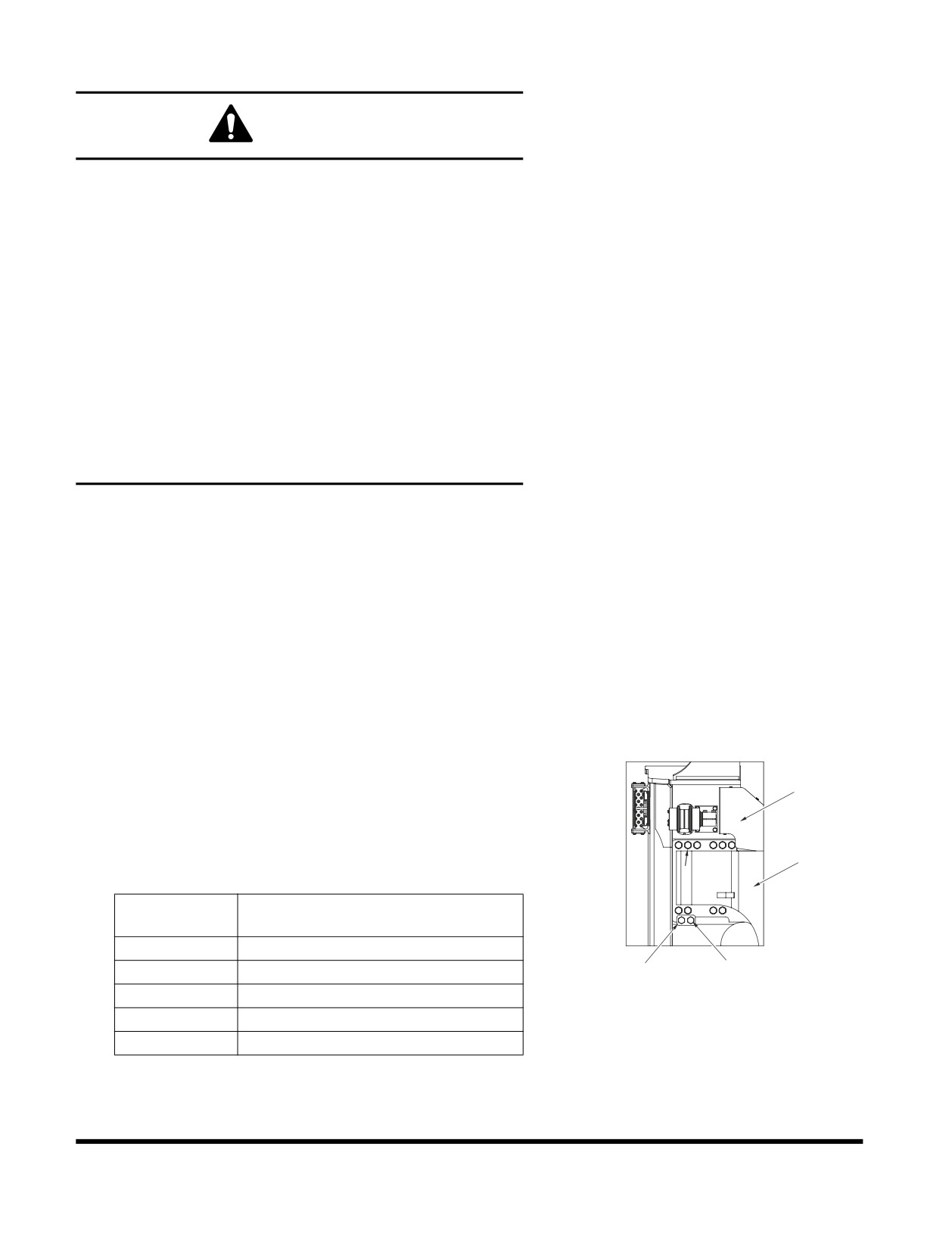
Remove ten bolts, harden washers and spacers (1, Figure
157) from side frame (2) to be retracted.
2
NOTE: Do not loosen two bolts (3, Figure 157) on guide
(4).
NOTE: Repeat procedure at other center frame support
5
(5, Figure 157).
1
Reference
Description
Number
1
Bolt
2
Side Frame
4
3
FG016362
Figure 157
3
Bolt
4
Guide
5
Center Frame Support
Transportation
OP001124
5-3
2.
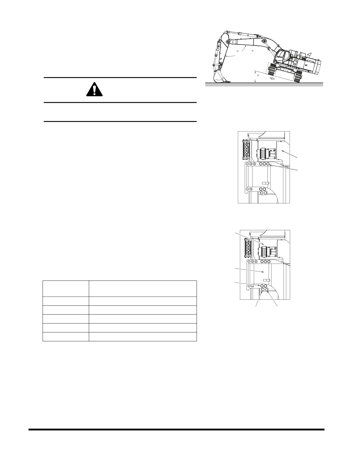
Turn superstructure so it is perpendicular to side frame to
be retracted. Raise side frame to approximately a 15°
angle from ground using a jack. Side frame should slide by
its own weight and hit against stop.
90 ~ 110
NOTE: If side frame does not slide in this condition,
allow side frame that is not contacting ground to
move back and forth slowly. See Figure 158.
15
CAUTION
FG016363
Figure 158
The arm must be set at a 90 - 110° angle. Never set it
at an angle less than 90°
3.
After side frame (1, Figure 159) has slid into place, lower
superstructure to ground. Install five spacers, harden
washers and bolts (2).
NOTE: Tighten bolts to 288 kg•m (2,083 ft lb).
1
NOTE: Repeat procedure at other center frame
2
support.
4.
After bolts for one side frame are fastened, repeat Steps 1
thru 3 for other side frame.
5.
Store remaining bolts, spacers and washers with machine.
FG016364
Figure 159
Frame Extension
1.
Remove five bolts, harden washers and spacers (1, Figure
2
160) from side frame (2) to be extended.
NOTE: Do not loosen two bolts (3, Figure 160) on guide
(4).
NOTE: Repeat procedure at other center frame support
5
(5, Figure 160).
1
Reference
Description
Number
1
Bolt
2
Side Frame
4
3
FG016365
3
Bolt
Figure 160
4
Guide
5
Center Frame Support
Transportation
OP001124
5-4
2.
Turn superstructure so it is perpendicular to side frame to
be extended.
NOTE: Do not attach cable on side frame step.
3.
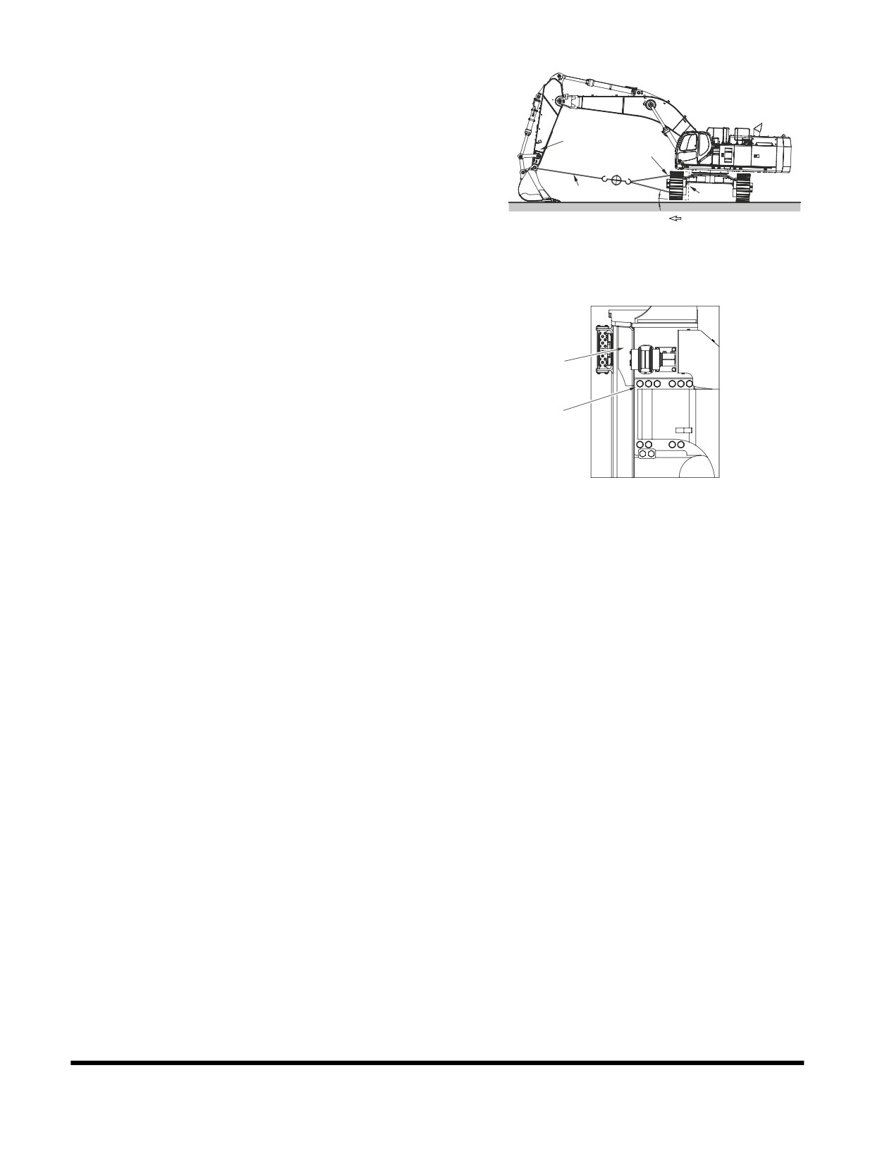
Attach one end of cable (1, Figure 161) (6 x 19 normal Z to
2
ø14 - ø16 A type) on arm (2) and other end on side frame
3
(3). Connect it with an appropriate holding device on both
ends.
1
4
4.
Raise side frame (3, Figure 161) slightly with jack and
block (4). Extend arm (2) gradually to slide side frame out
until it hits stop.
FG016366
Figure 161
5.
After side frame (1, Figure 162) has slid into place, lower
superstructure to ground. Remove cable.
6.
Install ten spacers, harden washers and bolts (2, Figure
162).
1
NOTE: Tighten bolts to 288 kg•m (2,083 ft lb).
NOTE: Repeat procedure at other track frame support.
2
7.
After bolts for one side frame are fastened, repeat Steps
thru 6 for other side frame.
FG016368
Figure 162
Transportation
OP001124
5-5
LOADING AND UNLOADING
Warning for Counterweight and Front
Attachment Removal
DANGER
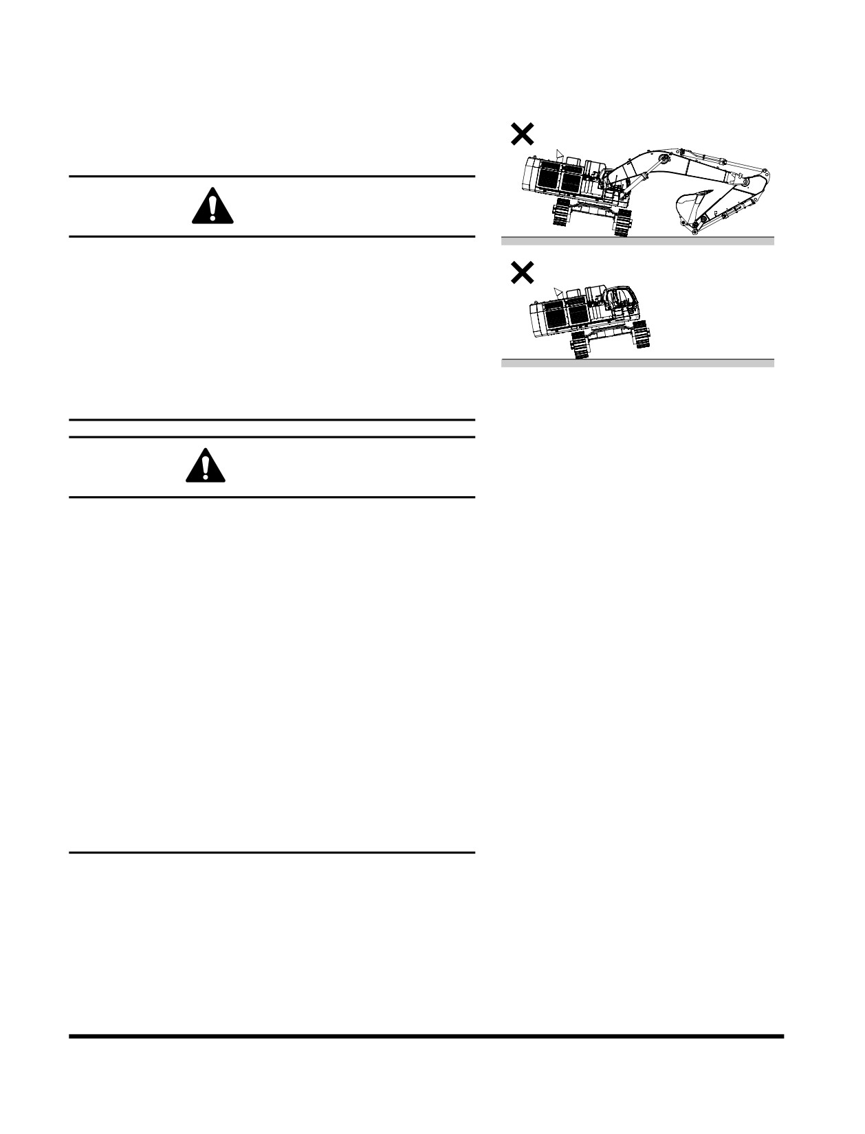
DOOSAN warns any user, that removal of counterweight
from machine, front attachment or any other part, may
affect stability of machine. This could cause unexpected
movement, resulting in death or serious injuries. DOOSAN
is not liable for any misuse.
Never remove counterweight or front attachment unless
upper structure is in-line with lower structure.
FG015763
Never rotate upper structure once counterweight or front
Figure 163
attachment has been removed.
WARNING
When transporting machine, know width, height, length and
weight.
Loading or unloading machine can be a dangerous
operation. Make sure to run engine at lowest speed setting,
and travel at slowest speed possible.
Make sure that ramp being used can handle weight of
machine. If required, add blocking under ramp for additional
support.
Make sure that ramp surface is free of grease or mud that
could cause machine to slip or slide.
Make sure that trailer is parked on firm, level ground before
attempting to load/unload excavator.
If it is required to turn machine while it is on trailer, make
sure to do this at slowest engine and travel speeds
possible.
Make sure to secure excavator onto trailer as required by
local transportation laws.
Transportation
OP001124
5-6

1.
EU
Boom and
Model
Arm
Total Height
Total Width
Total Length
Weight
Shoes
3.55 m
7.7 m (25' 3")
4,220 mm
3,410 mm
13,250 mm
70.1 metric tons
(11' 8")
boom
(13' 10")
(11' 2")
(43' 6")
(77.25 US tons)
arm
650 mm shoe
2.9 m
7.7 m (25' 3")
4,520 mm
3,650 mm
13,400 mm
70.4 metric tons
(9' 6")
boom
(14' 10")
(11' 12")
(43' 12")
(77.58 US tons)
arm
650 mm shoe
4.2 m
7.7 m (25' 3")
5,130 mm
3,650 mm
13,085 mm
70.1 metric tons
DX700LC
(13' 9")
boom
(16' 10")
(11' 12")
(42' 11")
(77.25 US tons)
arm
650 mm shoe
2.9 m
6.65 m (21' 10")
5,000 mm
3,650 mm
12,335 mm
65.8 metric tons
(9' 6")
boom
(16' 5")
(11' 12")
(40' 6")
(76.92 US tons)
arm
650 mm shoe
2.6 m
6.65 m (21' 10")
4,870 mm
3,650 mm
12,335 mm
72.0 metric tons
(8' 6")
boom
(15' 12")
(11' 12")
(40' 6")
(77.14 US tons)
arm
650 mm shoe
2.
North America
Boom and
Model
Arm
Total Height
Total Width
Total Length
Weight
Shoes
3.55 m
7.7 m (25' 3")
4,220 mm
3,650 mm
13,250 mm
71.9 metric tons
(11' 8")
boom
(13' 10")
(11' 12")
(43' 6")
(79.23 US tons)
arm
900 mm shoe
2.9 m
7.7 m (25' 3")
4,520 mm
3,650 mm
13,400 mm
72.2 metric tons
(9' 6")
boom
(14' 10")
(11' 12")
(43' 12")
(79.56 US tons)
arm
900 mm shoe
4.2 m
7.7 m (25' 3")
5,130 mm
3,650 mm
13,085 mm
71.9 metric tons
DX700LC
(13' 9")
boom
(16' 10")
(11' 12")
(42' 11")
(79.23 US tons)
arm
900 mm shoe
2.9 m
6.65 m (21' 10")
5,000 mm
3,650 mm
12,335 mm
71.6 metric tons
(9' 6")
boom
(16' 5")
(11' 12")
(40' 6")
(78.9 US tons)
arm
900 mm shoe
2.6 m
6.65 m (21' 10")
4,870 mm
3,650 mm
12,335 mm
71.8 metric tons
(8' 6")
boom
(15' 12")
(11' 12")
(40' 6")
(79.12 US tons)
arm
900 mm shoe
Transportation
OP001124
5-7
1.
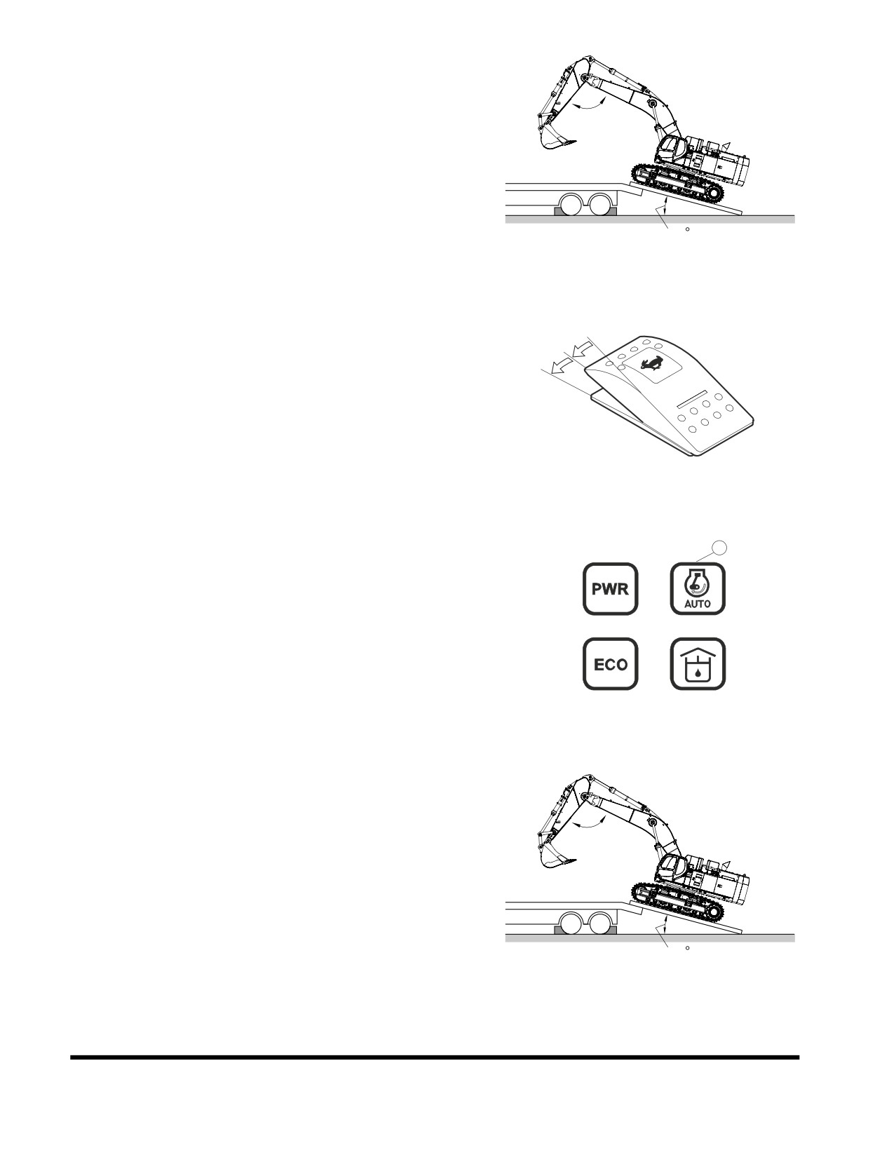
Make sure that trailer is parked on firm, level ground. See
Figure 164.
2.
Make sure that ramps that are being used are designed to
handle weight of excavator. If required, add blocking under
90 ~ 110
ramp to provide additional support.
3.
The ramp angle should be less than or not exceeding a 15°
angle. Ramps steeper than this may cause a problem
when loading or unloading.
15
FG015821
Figure 164
4.
Set travel speed selector switch to "O" (OFF) position. See
Figure 165.
O
I
II
FG000023
Figure 165
5.
Turn "OFF" auto idle selector button (1, Figure 166). The
1
indicator symbol will be disappeared.
6.
Set engine speed to "LOW IDLE".
1
2
6
7
FG013833
Figure 166
7.
If machine is equipped with work equipment, set work
equipment at front, and travel forward to load it.
90 ~ 110
15
FG015821
Figure 167
Transportation
OP001124
5-8
8.
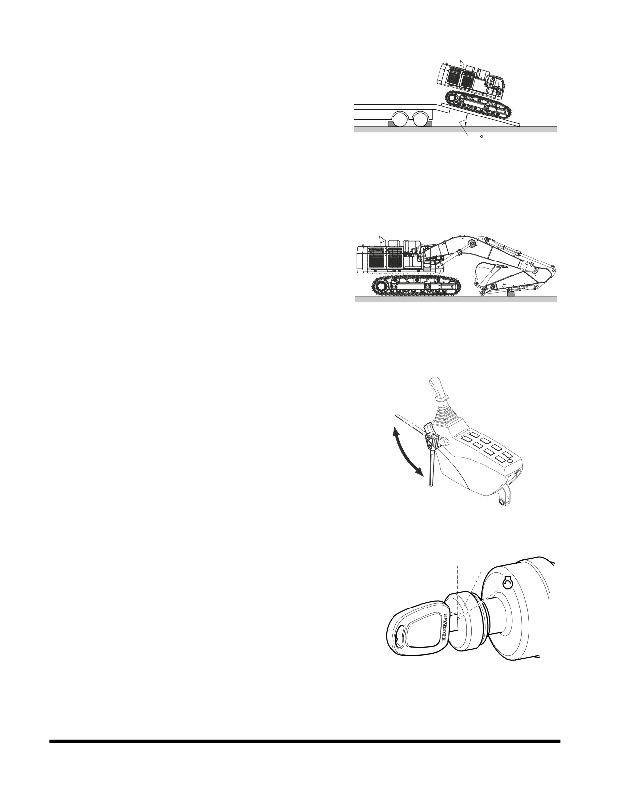
The unit does not require disassembly for normal
over-the-road transportation. If boom and arm need to be
removed, counterweight will place more weight on rear of
machine. Make sure to back excavator onto trailer so
counterweight end of excavator is positioned on ramp first.
See Figure 168.
15
FG016155
Figure 168
9.
Extend bucket and arm cylinders to maximum length and
then lower boom slowly.
FG015822
Figure 169
10. Set safety lever on "LOCK" position.
Unlock
Lock
FG001091
Figure 170
11. Shut down engine by turning key to "O" (OFF) position
(Figure 171).
O
I
12. Remove key from starter switch.
FG000175
Figure 171
Transportation
OP001124
5-9
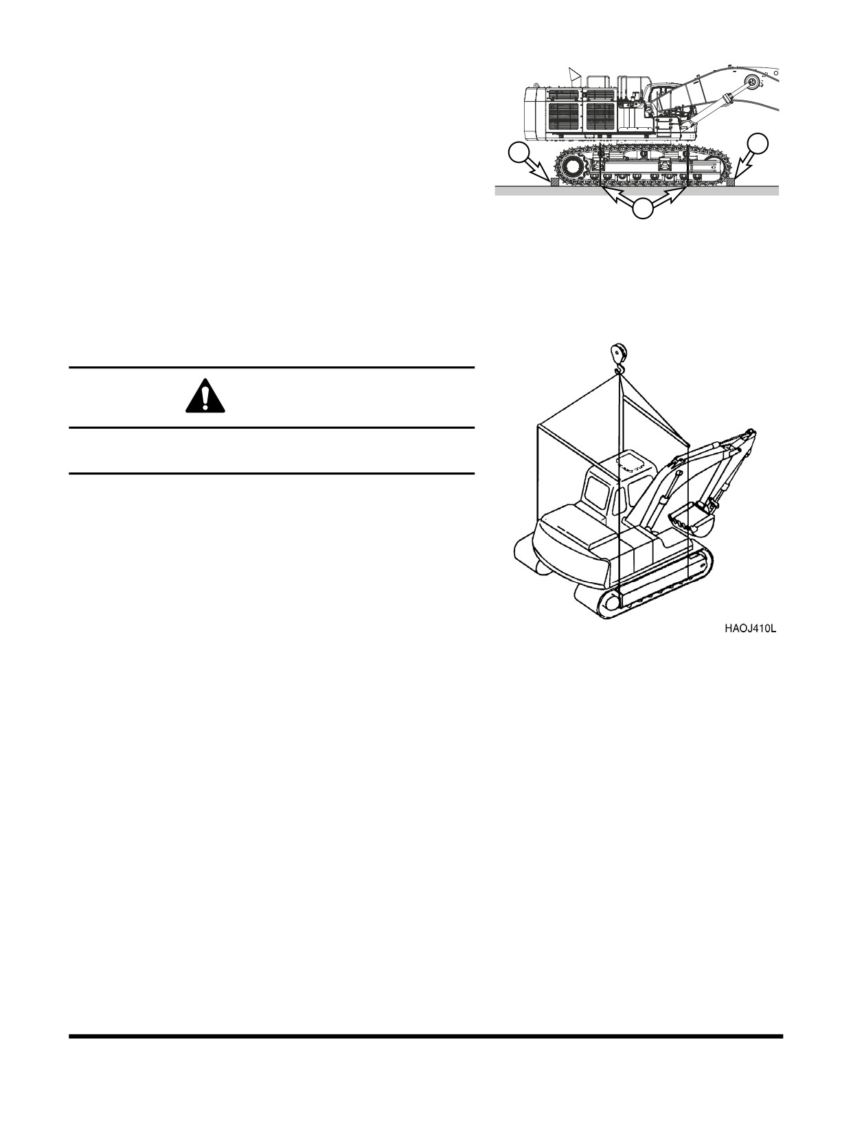
13. Make sure to secure excavator onto trailer before
transporting. Place blocking (1, Figure 172) in front of and
behind each track. Use chains or cable tie-downs (2) as
required by local transportation laws.
14. Refer to Dimensions for Transportation table and drawing
1
for overall machine height and width measurements. Make
1
sure to position excavator as shown. If not transported in
this position, height measurements may be different.
2
FG015857
Figure 172
LIFTING WITH SLING
WARNING
Improper lifting can allow load to shift and cause injury or
damage.
1.
Refer to “Specification” on page 7-1 of this manual for
information on weight and dimensions.
2.
Use properly rated cables and slings for lifting.
3.
Position machine for a level lift.
4.
Lifting cables should have a long enough length to prevent
contact with machine. Spreader bars may be required.
NOTE: If spreader bars are used, be sure that cables
Figure 173
are properly secured to them and that angle of
cables is factored into lift strength.
Transportation
OP001124
5-10
OP000030
6Troubleshooting
Anytime that a malfunction occurs, take immediate corrective
action. Check for and investigate the cause of the malfunction. A
schedule maintenance program can prevent malfunctions from
occurring by doing preventative maintenance. A systematic
approach should be taken to troubleshooting, since several
overlapping malfunctions may give the appearance of a problem
that does not exist. If cause for the malfunction cannot be
determined, contact your DOOSAN distributor. Never perform
an adjustment of or disassembly of, hydraulic components,
electrical and electronic components, without first consulting a
DOOSAN distributor.
ELECTRICAL SYSTEM
Problem
Cause
Remedy
Battery will not hold a
Low battery power.
Clean and retighten.
charge.
Alternator belt loose or bad.
Tighten or replace belt.
Loose or corroded terminals.
Tighten or replace as required.
Alternator faulty.
Repair or replace as required.
Low battery power.
Internal battery short.
Replace battery.
Short circuit in wiring.
Repair as required.
Engine speed is not
Speed control dial failed.
Replace control dial.
controllable.
Throttle controller failed.
Replace controller.
Speed control motor failed.
Repair or replace as required.
Blown fuse.
Replace fuse.
Wiring harness damaged.
Repair or replace as required.
Connector failed.
Repair or replace as required.
Power mode selector does
Blown fuse.
Replace fuse.
not work.
Power mode selector switch failed.
Replace switch.
Connector failed.
Replace connector.
Wiring harness damaged.
Repair or replace as required.
e-EPOS controller failed.
Repair or replace as required.
Troubleshooting
OP000030
6-1
Problem
Cause
Remedy
Working mode selector does
Blown fuse.
Replace fuse.
not work.
Working mode selector switch.
Replace switch failed.
Connector failed.
Replace connector.
Wiring harness damaged.
Repair or replace as required.
e-EPOS controller failed.
Repair or replace as required.
ENGINE
Problem
Cause
Remedy
Starter does not operate.
Low battery power.
Charge battery.
Poor terminal contact.
Clean and tighten connections.
Starter switch failed.
Replace switch.
Starter relay failed.
Replace relay.
Starter controller failed.
Replace controller.
Wiring harness faulty.
Replace harness.
Battery relay failed.
Replace relay.
Blown fuse.
Replace fuse.
Starter engages, engine
Fuel gelled in cold weather.
Replace fuel.
does not start.
Fuel filters plugged.
Replace filters.
Water or dirt in fuel system.
Clean system and add new fuel.
Air in fuel system.
Purge air from system.
Engine stop control failed.
Contact your DOOSAN dealer.
Engine stop relay failed.
Replace relay.
Blown fuse.
Replace fuse.
Engine starts, runs only at
Engine oil viscosity incorrect.
Change oil.
low speed or shuts down.
Clogged or dirty fuel injectors.
Clean injectors.
Fuel filters plugged.
Replace filters.
Troubleshooting
OP000030
6-2
Problem
Cause
Remedy
Engine knocks, runs
Low engine oil.
Refill.
unevenly or surges.
Plugged air intake system.
Clean system and replace filter.
Injection pump out of adjustment.
Contact your DOOSAN dealer.
Plugged fuel filter.
Replace fuel filter.
Water or dirt in fuel system.
Clean system and add new fuel.
Clogged or dirty fuel injectors.
Clean injectors.
Engine has poor power.
Plugged air intake system.
Clean system and replace filter.
Clogged or dirty fuel injectors.
Clean injectors.
Fuel filters plugged.
Replace filters.
Engine speed control cable out of
Readjust.
adjustment.
Injection pump out of adjustment.
Contact your DOOSAN dealer.
Valve backlash faulty.
Adjust backlash.
Engine runs hot.
Low coolant level.
Add coolant.
Thermostat faulty.
Replace thermostat.
Radiator cap faulty.
Replace radiator cap.
Radiator core plugged.
Clean radiator.
Oil cooler core plugged.
Clean oil cooler.
Fan belt loose or damaged.
Tighten or replace as required.
Temperature sensor faulty.
Replace sensor.
HYDRAULIC SYSTEM
Problem
Cause
Remedy
None of the controls
Hydraulic pump failed.
Contact your DOOSAN dealer.
function (loud noise from
Low hydraulic oil level.
Add hydraulic oil as required.
pumps).
Suction line plugged or damaged.
Clean or replace as required.
None of the controls
Pilot pump failure.
Contact your DOOSAN dealer.
function (no noise from
Cut off solenoid valve failed.
Replace solenoid.
pumps).
Pilot cutoff switch is ON.
Adjust pilot cutoff switch clearance.
Troubleshooting
OP000030
6-3
Problem
Cause
Remedy
All actuators have low
Low hydraulic oil level.
Add hydraulic oil as required.
power.
Suction filter clogged.
Clean filter.
Hydraulic pumps faulty.
Contact your DOOSAN dealer.
Main relief pressure too low.
Contact your DOOSAN dealer.
Hydraulic pumps excavating.
Bleed air from hydraulic pumps.
Only one or two actions
Overload relief pressure too low.
Reset pressure.
have little or no power.
Makeup check valve leaking.
Clean or replace as required.
Control valve spool faulty.
Replace valve spool.
Dirt in valve spool.
Clean or replace as required.
Actuator failed.
Repair or replace as required.
Cylinder seal failed.
Repair or replace as required.
Cylinder rod damaged.
Repair or replace as required.
Remote control valve failed.
Replace control valve.
Wrong pilot line connection.
Reconnect pilot lines.
Oil temperature too high.
Oil cooler faulty.
Contact your DOOSAN dealer.
Fan belt loose.
Tighten fan belting as required.
SWING SYSTEM
Problem
Cause
Remedy
No swinging motion.
Swing brake valve faulty.
Replace brake valve.
Hydraulic timer faulty.
Replace timer.
Low brake release pressure.
Adjust pressures.
Swing motor failed.
Replace swing motor.
Remote control valve failed.
Replace control valve.
Wrong pilot line connection.
Reconnect pilot lines.
Swing motion jerky.
Swing gear worn.
Replace swing gear.
Swing bearing damaged.
Replace bearing.
Improper lubrication.
Add grease.
Troubleshooting
OP000030
6-4
TRAVEL SYSTEM
Problem
Cause
Remedy
Travel motion does not
Center joint leaking.
Repair or replace as required.
function.
Parking brake will not release.
Repair parking brake.
Travel motor failed.
Repair or replace as required.
Remote control valve failed.
Repair or replace as required.
Wrong pilot line connection.
Reconnect pilot lines.
Travel speed is too low.
Track tension too high or too low.
Adjust tension.
Damaged rollers or idlers.
Repair or replace as required.
Track frame damaged.
Repair as required.
Parking brake will not release.
Repair parking brake.
Troubleshooting
OP000030
6-5
Troubleshooting
OP000030
6-6
OP001125
7Specification
1.
EU
1)
Specification
SPECIFICATION
COMPONENT
METRIC
ENGLISH
Bucket
CECE
2.9 m3
3.79 yd3
capacity
PCSA
3.3 m3
4.32 yd3
Equipment weight
70.4 metric tons
77.5 U.S. tons
Engine
Model
ISUZU AH-6WGIX
Type
Water cooled - 6 cylinders
Rated output
345 kw @1,800 rpm
463 hp @1,800 rpm
Maximum torque
202 kg•m @ 1,300 rpm
1,461 ft lb @ 1,300 rpm
Fuel tank capacity
900 liters
237.8 U.S. gal.
Hydraulic
Type
Tendem, Axial piston
pump
Discharging pressure
5,000 psi
350 kg/cm2
Maximum discharge quantity
2 x 436 liters/min
2 x 115.2 U.S. gpm
Hydraulic oil
Tank Level
350 liters
92.5 U.S. gal.
capacity
System
790 liters
208.7 U.S. gal.
Performance
Digging 1)
Bucket
35.7/34.8 metric tons
39.3/38.3 tons
capability
Arm
29.3/33.5 metric tons
32.3/36.9 tons
Swing speed
7.1 rpm
Travel speed
High speed
4.6 km/h
2.86 MPH
Low speed
2.8 km/h
1.74 MPH
Traction force
High speed
42.4 metric tons
46.7 tons
Low speed
48.9 metric tons
53.9 tons
Gradeability
35° (70% slope)
Ground pressure
1.02 kg/cm2
14.5 psi
Ground clearance
870 mm
34.25 in
Track shoe width
650 mm
25.6 in
Upper roller qty.
3 per side
Bottom roller qty.
8 per side
NOTE:
1) 3.55 m (11' 8") Arm / 2.9 m (9' 6") Arm
Specification
OP001125
7-1
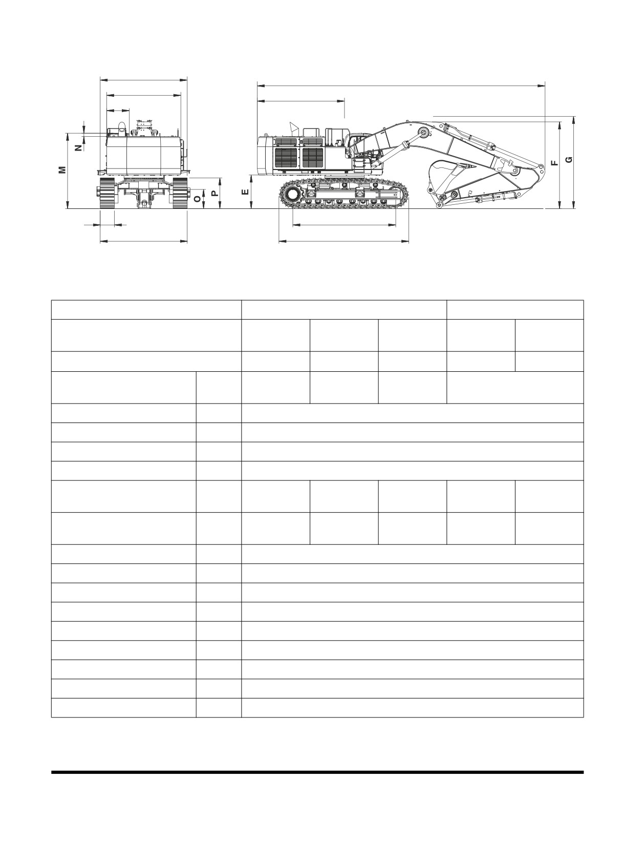
2)
Overall Dimensions
H
A
I
B
J
K
C
L
D
FG015838
Figure 1
Boom Type (One Piece)
7.7 m (25' 3")
6.65 m (21' 10")
3.55 m
2.9 m
4.2 m
2.9 m
2.6 m
Arm Type
(11' 8")
(9' 6")
(13' 9")
(9' 6")
(8' 6")
Bucket Type (SAE)
3.3 m3
3.3 m3
3.0 m3
3.9 m3
4.5 m3
13,250 mm
13,400 mm
13,085 mm
12,335 mm
Shipping Length
A
(43' 6")
(43' 12")
(42' 11")
(40' 6")
Tail Swing Radius
B
4,090 mm (13' 5")
Tumbler Distance
C
4,730 mm (15' 6")
Track Length
D
5,975 mm (19' 7")
C/Weight Clearance
E
1,525 mm (5' 0")
4,063 mm
4,418 mm
5,015 mm
4,920 mm
4,750 mm
Shipping Height (Boom)
F
(13' 4")
(14' 6")
(16' 5")
(16' 2")
(15' 7")
4,220 mm
4,520 mm
5,130 mm
5,000 mm
4,870 mm
Shipping Height (Hose)
G
(13' 10")
(14' 10")
(16' 10")
(16' 5")
(15' 12")
Shipping Width (Std.)
H
3,410 mm (11' 2")
House Width
I
3,410 mm (11' 2")
Cab. Width
J
1,010 mm (3' 4")
Shoe Width
K
650 mm (2' 2")
Undercarriage Width (Std.)
L
3,400 mm (11' 2")/4,000 mm (13' 1")*
Height Over Cab.
M
3,515 mm (11' 6")
Cab. Height Above House
N
208 mm (8")
Car Body Clearance
O
870 mm (2' 10")
Track Height
P
1,413 mm (4' 8")
NOTE:
* Retracted/Extended.
Specification
OP001125
7-2
Specification
OP001125
7-3
2.
North America
1)
Specification
SPECIFICATION
COMPONENT
METRIC
ENGLISH
Bucket
CECE
2.9 m3
3.79 yd3
capacity
PCSA
3.3 m3
4.32 yd3
Equipment weight
71.9 metric tons
79.2 tons
Engine
Model
ISUZU AH-6WGIX
Type
Water cooled - 6 cylinders
Rated output
345 kw @1,800 rpm
463 hp @1,800 rpm
Maximum torque
202 kg•m @ 1,300 rpm
1,461 ft lb @ 1,300 rpm
Fuel tank capacity
900 liters
237.8 U.S. gal.
Hydraulic
Type
Tendem, Axial piston
pump
Discharging pressure
350 kg/cm2
5,000 psi
Maximum discharge quantity
2 x 436 liters/min
2 x 115.2 U.S. gpm
Hydraulic oil
Tank Level
350 liters
92.5 U.S. gal.
capacity
System
790 liters
208.7 U.S. gal.
Performance
Digging 1)
Bucket
35.7 metric tons
39.3 tons
capability
Arm
29.3 metric tons
32.3 tons
Swing speed
7.1 rpm
Travel speed
High speed
4.6 km/h
2.86 MPH
Low speed
2.8 km/h
1.74 MPH
Traction force
High speed
42.4 metric tons
46.7 tons
Low speed
48.9 metric tons
53.9 tons
Gradeability
35° (70% slope)
Ground pressure
0.76 kg/cm2
10.8 psi
Ground clearance
870 mm
34.25 in
Track shoe width
900 mm
35.43 in
Upper roller qty.
3 per side
Bottom roller qty.
8 per side
Specification
OP001125
7-4
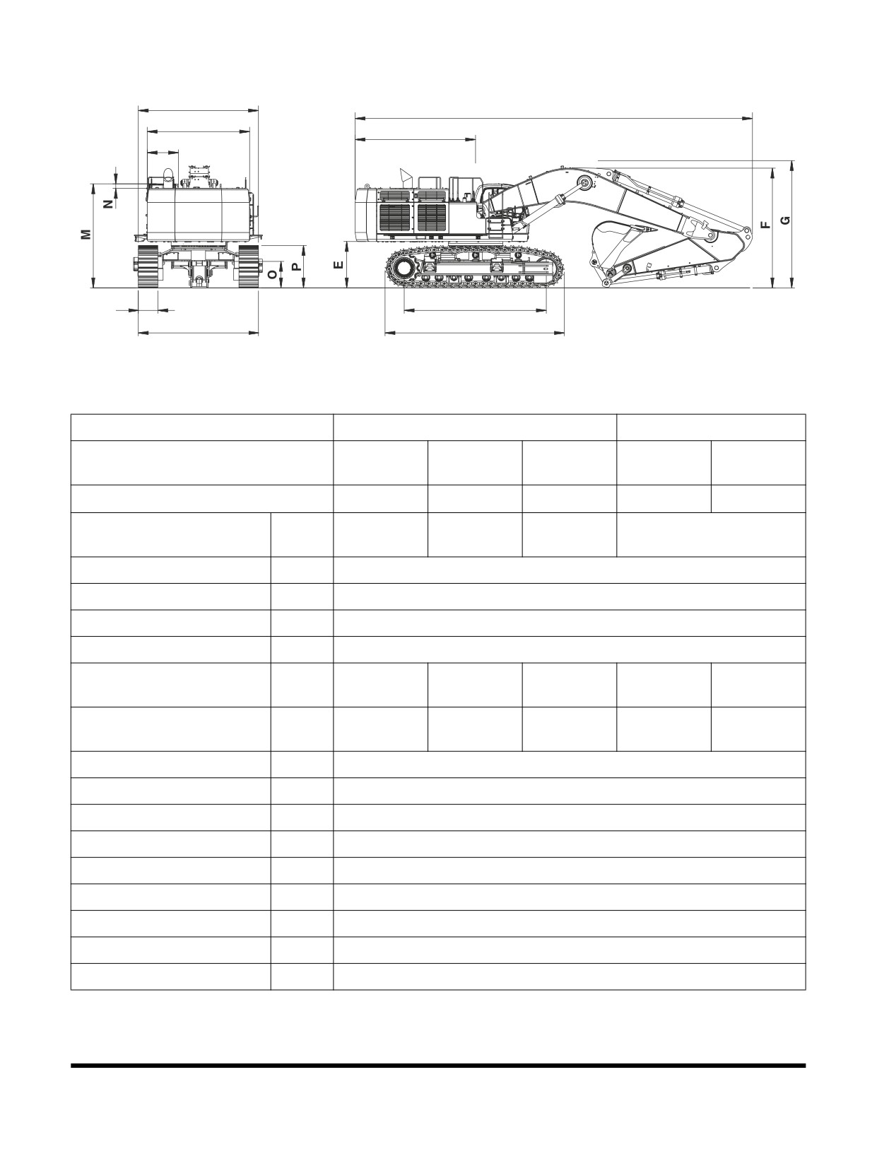
2)
Overall Dimensions
H
A
I
B
J
K
C
L
D
FG015838
Figure 2
Boom Type (One Piece)
7.7 m (25' 3")
6.65 m (21' 10")
3.55 m
2.9 m
4.2 m
2.9 m
2.6 m
Arm Type
(11' 8")
(9' 6")
(13' 9")
(9' 6")
(8' 6")
Bucket Type (SAE)
3.3 m3
3.3 m3
3.0 m3
3.9 m3
4.5 m3
13,250 mm
13,400 mm
13,085 mm
12,335 mm
Shipping Length
A
(43' 6")
(43' 12")
(42' 11")
(40' 6")
Tail Swing Radius
B
4,090 mm (13' 5")
Tumbler Distance
C
4,730 mm (15' 6")
Track Length
D
5,975 mm (19' 7")
C/Weight Clearance
E
1,525 mm (5' 0")
4,063 mm
4,418 mm
5,015 mm
4,920 mm
4,750 mm
Shipping Height (Boom)
F
(13' 4")
(14' 6")
(16' 5")
(16' 2")
(15' 7")
4,220 mm
4,520 mm
5,130 mm
5,000 mm
4,870 mm
Shipping Height (Hose)
G
(13' 10")
(14' 10")
(16' 10")
(16' 5")
(15' 12")
Shipping Width (Std.)
H
3,410 mm (11' 2")
House Width
I
3,410 mm (11' 2")
Cab. Width
J
1,010 mm (3' 4")
Shoe Width
K
900 mm (2' 11")
Undercarriage Width (Std.)
L
3,650 mm (11' 12")/4,250 mm (13' 11")*
Height Over Cab.
M
3,515 mm (11' 6")
Cab. Height Above House
N
208 mm (8")
Car Body Clearance
O
870 mm (2' 10")
Track Height
P
1,413 mm (4' 8")
NOTE:
* Retracted/Extended.
Specification
OP001125
7-5
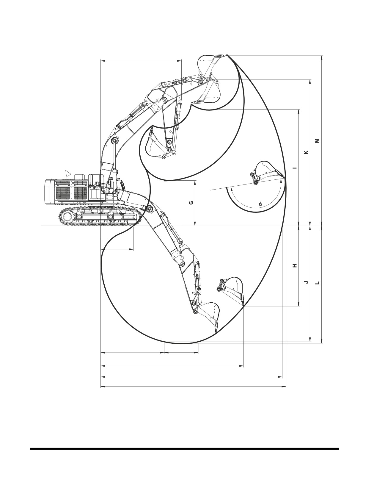
Working Range
F
Ground
E
D
8'
C
B
A
FG015858
Figure 3
Specification
OP001125
7-6
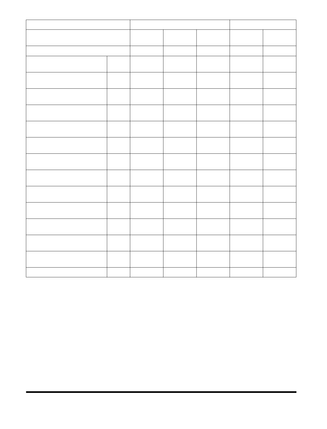
Boom Type (One Piece)
7.7 m (25' 3")
6.65 m (21' 10")
3.55 m
2.9 m
4.2 m
2.9 m
2.6 m
Arm Type
(11' 8")
(9' 6")
(13' 9")
(9' 6")
(8' 6")
Bucket Type (SAE)
3.3 m3
3.3 m3
3.0 m3
3.9 m3
4.5 m3
13,250 mm
12,720 mm
13,865 mm
11,605 mm
11,345 mm
Max. Digging Reach
A
(43' 6")
(41' 9")
(45' 6")
(38' 1")
(37' 3")
12,990 mm
12,450 mm
13,610 mm
11,305 mm
11,040 mm
Max. Digging Reach (Ground)
B
(42' 7")
(40' 10")
(44' 8")
(37' 1")
(36' 3")
10,230 mm
10,790 mm
10,360 mm
9,860 mm
9,655 mm
Max. Radius Vertical
C
(33' 7")
(35' 5")
(33' 12")
(32' 35")
(31' 8")
4,540 mm
4,530 mm
10,360 mm
3,800 mm
3,785 mm
Min. Radius 8' Line
D
(14' 11")
(14' 10")
(33' 12")
(12' 6")
(12' 5")
2,350 mm
3,060 mm
170 mm
1,835 mm
2,050 mm
Min. Digging Reach
E
(7' 9")
(10' 0")
(7")
(6' 0")
(6' 9")
5,780 mm
5,790 mm
5,810 mm
5,230 mm
5,195 mm
Min. Swing Radius
F
(18' 12")
(18' 12")
(19' 1")
(17' 2")
(17' 1")
3,248 mm
3,950 mm
2,630 mm
3,080 mm
3,380 mm
Min. Loading Height
G
(10' 8")
(12' 12")
(8' 8")
(10' 1")
(11' 1")
5,730 mm
4,060 mm
6,515 mm
3,450 mm
3,305 mm
Max. Vertical Wall Depth
H
(18' 10")
(13' 4")
(21' 4")
(11' 4")
(10' 10")
8,320 mm
8,220 mm
8,660 mm
7,020 mm
6,940 mm
Max. Loading Height
I
(27' 4")
(26' 12")
(28' 5")
(23' 0")
(22' 9")
8,270 mm
7,550 mm
8,910 mm
6,925 mm
6,620 mm
Max. Depth To 8' Line
J
(27' 2")
(24' 9")
(29' 3")
(22' 9")
(21' 9")
10,470 mm
10,380 mm
10,795 mm
9,210 mm
9,135 mm
Max. Bucket Pin Height
K
(34' 4")
(34' 1")
(35' 5")
(30' 3")
(29' 12")
8,410 mm
7,730 mm
9,030 mm
7,075 mm
6,780 mm
Max. Digging Depth
L
(27' 7")
(25' 4")
(29' 8")
(23' 3")
(22' 3")
12,165 mm
12,040 mm
12,520 mm
10,740 mm
10,680 mm
Max. Digging Height
M
(39' 11")
(39' 6")
(41' 1")
(35' 3")
(35' 0")
Bucket Angle
d
179.4 deg
177.8 deg
179.4 deg
167.4 deg
166.4 deg
Specification
OP001125
7-7
APPROXIMATE WEIGHT OF
WORKLOAD MATERIALS
IMPORTANT
Weights are approximations of estimated average volume
and mass. Exposure to rain, snow or ground water; settling
or compaction due to overhead weight and chemical or
industrial processing or
changes due to thermal or
chemical transformations
could
all
increase value of
weights listed in table.
LOW WEIGHT OR
MEDIUM WEIGHT OR
HIGH WEIGHT OR
DENSITY
DENSITY
DENSITY
MATERIAL
1,100 KG/M3
1,600 KG/M3
2,000 KG/M3
(1,850 LB/YD3), OR
(2,700 LB/YD3), OR
(3,370 LB/YD3), OR
LESS
LESS
LESS
3
401 kg/m
Charcoal
---------------------
---------------------
(695 lb/yd3)
3
433 kg/m
Coke, blast furnace size
---------------------
---------------------
(729 lb/yd3)
3
449 kg/m
Coke, foundry size
---------------------
---------------------
(756 lb/yd3)
3
801 kg/m
Coal, bituminous slack, piled
---------------------
---------------------
(1,350 lb/yd3)
3
881 kg/m
Coal, bituminous r. of m., piled
---------------------
---------------------
(1,485 lb/yd3)
3
897 kg/m
Coal, anthracite
---------------------
---------------------
(1,512 lb/yd3)
3
1,009 kg/m
Clay, DRY, in broken lumps
---------------------
---------------------
(1,701 lb/yd3)
3
1,746 kg/m
Clay, DAMP, natural bed
---------------------
---------------------
(2,943 lb/yd3)
3
1,506 kg/m
Cement, Portland, DRY granular
---------------------
---------------------
(2,583 lb/yd3)
3
1,362 kg/m
Cement, Portland, DRY clinkers
---------------------
---------------------
(2,295 lb/yd3)
3
1,522 kg/m
Dolomite, crushed
---------------------
---------------------
(2,565 lb/yd3)
3
1,202 kg/m
Earth, loamy, DRY, loose
---------------------
---------------------
(2,025 lb/yd3)
3
1,522 kg/m
Earth, DRY, packed
---------------------
---------------------
(2,565 lb/yd3)
3
1,762 kg/m
Earth, WET, muddy
---------------------
---------------------
(2,970 lb/yd3)
Specification
OP001125
7-8
LOW WEIGHT OR
MEDIUM WEIGHT OR
HIGH WEIGHT OR
DENSITY
DENSITY
DENSITY
MATERIAL
1,100 KG/M3
1,600 KG/M3
2,000 KG/M3
(1,850 LB/YD3), OR
(2,700 LB/YD3), OR
(3,370 LB/YD3), OR
LESS
LESS
LESS
3
961 kg/m
Gypsum, calcined, (heated, powder)
---------------------
---------------------
(1,620 lb/yd3)
3
1,522 kg/m
Gypsum, crushed to 3 inch size
---------------------
---------------------
(2,565 lb/yd3)
3
1,810 kg/m
Gravel, DRY, packed fragments
---------------------
---------------------
(3,051 lb/yd3)
3
1,922 kg/m
Gravel, WET, packed fragments
---------------------
---------------------
(3,240 lb/yd3)
3
1,282 kg/m
Limestone, graded above 2
---------------------
---------------------
(2,160 lb/yd3)
Limestone, graded
1,362 kg/m3
---------------------
---------------------
1-1/2 or 2
(2,295 lb/yd3)
3
1,522 kg/m
Limestone, crushed
---------------------
---------------------
(2,565 lb/yd3)
3
1,602 kg/m
Limestone, fine
---------------------
---------------------
(2,705 lb/yd3)
3
1,282 kg/m
Phosphate, rock
---------------------
---------------------
(2,160 lb/yd3)
3
929 kg/m
Salt
---------------------
---------------------
(1,566 lb/yd3)
3
529 kg/m
Snow, light density
---------------------
---------------------
(891 lb/yd3)
3
1,522 kg/m
Sand, DRY, loose
---------------------
---------------------
(2,565 lb/yd3)
3
1,922 kg/m
Sand, WET, packed
---------------------
---------------------
(3,240 lb/yd3)
3
1,362 kg/m
Shale, broken
---------------------
---------------------
(2,295 lb/yd3)
3
529 kg/m
Sulphur, broken
---------------------
---------------------
(1,620 lb/yd3)
Specification
OP001125
7-9
Specification
OP001125
7-10
1INDEX
Numerics
Tooth 4-71
1,000 Hour / 6 Month Service 4-43
10 Hour / Daily Service 4-14
C
12,000 Hour / 6 Year Service 4-56
Cabin Light 2-56
2,000 Hour / Yearly Service 4-49
Cabin Storage Compartments 2-66
250 Hour / Monthly Service 4-28
Cabin Work Light Switch 2-12
4,000 Hour / Biennial Service 4-55
Ceiling Cover 2-62
50 Hour / Weekly Service 4-25
Charge Warning Light 2-24
500 Hour / 3 Month Service 4-34
Check and Confirmation After Stopping Engine
3-13
A
Cigarette Lighter 2-14
Abnormal State Warning Symbols 2-29
Circuit Breaker 2-56
Adjust Valve Clearance 4-54
Clock 2-23, 2-38
Air Intake System 4-23
Cold Weather Hydraulic System Warm-up 3-10
Outer Element of Air Cleaner 4-39
Cold Weather Starting 3-6
Replace Outer Air Cleaner Element 4-50
Communication
Alternator and Starter 4-54
Error Warning 2-28
Antifreeze Concentration Tables 4-82
Indicator 2-27
Antivibration Shock Mounts 4-54
Component Locations 2-2
Arm and Bucket Joint Pins 4-25
Constant Speed Button 2-13
Ashtray 2-66
Coolant Temperature Warning Light 2-25
Audio Control Panel 2-10
Cooling System
Auto Idle Mode 3-20
Clean Radiator, Oil Cooler and Air Conditioner
Auto Idle Selection 2-47
Condenser Coil 4-38
Auto Idle Selector Button 2-34
Engine 4-78
Auxiliary Mode Switch 2-9
Engine Coolant Temperature Warning Light
2-25
Oil Cooler Dust Net 4-20
B
Radiator Coolant 4-51
Batteries 4-33
Refill Cooling System 4-21
Battery 4-74
Counterweight and Front Attachment Removal 5-6
Box Door 2-69
Cracks and Faulty Welds 4-23
Electrolyte Level 4-75
Cup Holder 2-68
Terminals 4-75
Cycle Time Tests 4-54
Voltage 2-28
Bolt and Nut Inspection 4-58
D
Boom and Arm Joint Pins 4-28
Boost Mode 3-21
Description of Lubrication and Service Chart 4-10
Booster Button 2-17
Digital Clock 2-23
Booster Cable 3-7
Display Selection 2-37
Breaker Selection 2-47
Display Selector Button 2-36
Bucket 4-71
Door Side Latch 2-65
Installation 4-73
Door Window Holder 2-68
O-ring 4-72
Down Arrow Button 2-36
Shimming Procedures 4-73
Shimming Procedures for Installed Bucket 4-73
E
Teeth and Side Cutters 4-22
Economy Mode Selection 2-46
Index
950106-00012E
8-1
Electrical System 4-74, 6-1
G
Engine 6-2
Gauges
Adjust Valve Clearance 4-54
Engine Coolant Temperature Gauge 2-22
Check and Adjust Engine 4-48
Fuel Gauge 2-22
Check Warning Light 2-25
Hour Meter 2-24
Coolant Temperature Gauge 2-22
Hydraulic Oil Temperature 2-23
Coolant Temperature Warning Light 2-25
Multifunction Gauge 2-23, 2-27
Cover 2-69
General Venting 4-89
Emergency Stop Switch 2-9
Fan Belt 4-30, 4-31
H
Head Bolt Torques 4-54
Handling a New Excavator 3-1
Oil and Filter 4-27, 4-35
Handling of Accumulator 4-85
Oil Level 4-14
Hanger 2-67, 2-68
Oil Pressure Warning Light 2-24
Head Bolt Torques 4-54
Shutdown 3-12
Headlight Switch 2-11
Speed 2-28
Heater and Air Conditioner 2-49
Speed Control Dial 2-8
Additional Operating Instruction 2-54
Start 3-4
Control Panel 2-13, 2-50
Start and Stop 3-2
Filter 4-36, 4-47
ESC Button 2-37
Location of Controls and Vents 2-49
Excavator Rated Lift Capacity Tables 1-48
Memory Function of Used Mode 2-54
Extension and Retraction of Track Frames 5-3
Refrigerant 4-48
System 4-57
F
Horn Button 2-16
Fan Belt 4-27
Hose Clamps 4-33
Filter / Oil Info 2-39
Hour Meter 2-24
Filter State 2-29
Hydraulic System 6-3
Flow Control 2-44
Flow Control 2-44
Flow Control Button 2-34
Front Hydraulic Pump Pressure 2-29
Frame
General Venting 4-89
Extension 5-4
Hydraulic Breaker 3-32
Retraction 5-3
Hydraulic Hoses and Tubing 3-32
Front
Oil and Filter 3-36
Bottom Window 2-64
Operation 3-33
End Attachments 4-33
Selection 3-32
Hydraulic Pump Pressure 2-29
Hydraulic Cylinders 4-88
Upper Windows 2-63
Hydraulic Oil Exchange 4-52
Windows 2-63
Hydraulic Oil Return Filter 4-33, 4-44
Fuel
Hydraulic Oil Tank 4-15
Filter 4-42
Hydraulic Oil Temperature Gauge 2-23
Gauge 2-22
Leaks in the Hydraulic System 4-16
Heater Switch 2-16
Main System Pump 4-88
Level 4-17
Oil Exchange 4-52
System 4-42
Rear Hydraulic Pump Pressure 2-29
Transfer Pump 4-83
Swing Motor 4-89
Tank Drain Valve 4-27
Warm-up 3-9
Transfer Pump 4-83
Fuse
I
Boxes 2-57, 4-76
Indicator
Fuses 4-76
Communication Indicator 2-27
Fusible Link 2-57
Indicator Lights
Identification 4-77
Charge Warning Light 2-24
Coolant Temperature Warning Light 2-25
Engine Check Warning 2-25
Index
950106-00012E
8-2
Engine Oil Pressure Warning Light 2-24
Extreme Heat 3-43
Preheating Indicator Light 2-26
High Altitudes 3-45
Work Light 2-26
Rainy or Humid Conditions 3-44
Inspecting Engine Before Starting 3-2
Salt Water Areas 3-44
Inspection, Maintenance and Adjustment 4-1
Operation of All Switches 4-23
Instrument Panel 2-18, 2-20
Operation Selection Display 2-46
Intermittent Speed Button 2-14
Operation Under Unusual Conditions 3-42
Operational Checks Before Starting Engine 3-3
Operational Controls and Panels 2-6
L
Operator's Area 2-4
Language 2-38
Operator's Compartment Light 2-56
Leaks in the Fuel System 4-18
Outer Air Cleaner Element 4-50
Leaks in the Hydraulic System 4-16
Outer Element of Air Cleaner 4-39
Levers
Overall Dimensions 7-2
Adjusting Reclining 2-59
Overload Warning Switch (Optional) 2-15
Adjusting the Seat Forward 2-58
Adjusting the Seat's Angle 2-58
Angle Adjustment of Armrest 2-59
P
Safety Lever 2-18
Panels
Lifting 3-40
Air Conditioner Control Panel 2-13
Lifting With Sling 5-10
Audio Control 2-10
Lights
Heater and Air Conditioner 2-49
Cabin 2-56
Heater and Air Conditioner Control Panel 2-50
Loading and Unloading 5-6
Instrument 2-18
Locations of Safety Labels 1-4
Instrument Panel 2-20
Long Term Storage 4-90
Wiper Switch 2-13
Lubrication and filters 3-2
Parking Excavator 3-30
Lubrication and Service Chart 4-8
Password
Activated 2-21
Set Password 2-42
M
Password Activated 2-21
Magnetic Clutch 4-57
Photo Sensor 2-18
Main Menu 2-35
Pilot Cutoff Switch 2-56
Maintenance in Special Conditions 4-92
Pilot Filter 4-33, 4-45
Maintenance Intervals 4-12
Pins and Bushings 4-33
Miscellaneous Access Doors 2-69
Power Boost Selection 2-47
Mode Selection 3-19
Power Mode 3-19
Mode Selector Buttons 2-33
Power Mode Selection 2-46
Multifunction Gauge 2-23, 2-27
Power Mode Selector Button 2-33
Power Socket 2-15
N
Preheating Light 2-26
Nuts and Bolts 4-33
Preliminary Work Machine Setup for Maintenance
4-4
O
Preventive Maintenance 4-1
Oil Cooler Dust Net 4-20
Pump Pressure
Oil Level of Travel Reducer 4-32
Front Pump 2-29
Opening the Window 2-63
Rear Pump 2-29
Operating
Controls 2-1
Q
Instructions 3-19
Quick Clamp Operation Selection 2-48
Precautions 3-25
Quick Clamp Switch (Optional) 2-9
Techniques 3-40
Operation 3-1
R
Operation In
Radiator Coolant 4-51
Extreme Cold 3-42
Rear Hydraulic Pump Pressure 2-29
Index
950106-00012E
8-3
Refill Cooling System 4-21
Stereo 2-55
Rotating Buttons 2-17
Audio Control Panel 2-10
Rotating Pedal Valve (Optional) 3-39
Structural Damage 4-54
Suction Strainer 4-52
Sun Visor 2-67
S
Swing
Safety 1-1
Bearing 4-26
Safety Lever 2-18, 3-13
Gear and Pinion 4-34
Safety Precautions 4-3
Motor 4-89
Seat 2-58
Reduction Device 4-19, 4-33, 4-43, 4-49
Seat Adjustment
System 6-4
Adjusting Reclining 2-59
Switches
Adjusting the Seat Forward 2-58
Auto Idle Selector Button 2-34
Adjusting the Seat's Angle 2-58
Automatic Travel Speed Control 3-14
Adjustment of Lumbar Support 2-59
Auxiliary Mode 2-9
Air Suspension Seat 2-61
Booster Button 2-17
Angle Adjustment of Armrest 2-59
Cabin Work Light Switch 2-12
Headrest 2-59
Cigar Lighter 2-14
Left ad Right Control Stand Location 2-61
Constant Speed Button 2-13
Left and Right Control Stand Elevation Height
Display Selector Button 2-36
2-61
Down Arrow Button 2-36
Seat Belt 2-60, 4-23
Economy Mode Selector Button 2-33
Seat Warmer Switch (Optional) 2-16
Engine Emergency Stop 2-9
Selection Button 2-36
Engine Speed Control 3-19
Selection of
Engine Speed Control Dial 2-8
Breaker 2-46, 2-47
ESC Button 2-37
Overload Alarm 2-47
Flow Control Button 2-34
Power Boost Selection 2-46, 2-47
Fuel Heater 2-16
Quick Clamp Operation 2-48
Headlight Switch 2-11
Shear 2-46, 2-47
Home Button 2-36
Serial Numbers 4-3
Horn Button 2-16
Set Password 2-42
Intermittent Speed Button 2-14
Setting Clock 2-38
Overload Warning (Optional) 2-15
Shear Buttons 2-17
Pilot Cutoff Switch 2-56
Shear Pedal Valve (Optional) 3-38
Power Mode Selector Button 2-33
Shear Selection 2-47
Power Socket 2-15
Shimming Procedures for Installed Bucket 4-73
Quick Clamp (Optional) 2-9
Shutdown
Rotating Buttons 2-17
Check and Confirmation After Stopping Engine
Seat Warmer (Optional) 2-16
3-13
Selection Button 2-36
Engine Shutdown 3-12
Shear Buttons 2-17
Parking Excavator 3-30
Starter Switch 2-8
Side Door 2-69
Travel Speed Selector Switch 2-11
Specification 7-1
Travel/Swing Alarm (Optional) 2-15
Standard Mode Selection 2-46
Up Arrow Button 2-35
Starter Switch 2-8
Warning Light 2-12
Starting Engine Using a Booster Battery 3-7
Washer Button 2-14
Start-up
Wiper Switch (Lower) 2-13
Cold Weather Hydraulic System Warm-up 3-10
Symbols
Cold Weather Starting 3-6
Air Cleaner Clogged Warning 2-31
Engine Start 3-4
Hydraulic Oil Overheat Warning 2-30
Hydraulic System Warm-up 3-9
Overload Warning (Optional) 2-32
Inspection Before Starting Engine 3-2
Pilot Filter Clogged Warning 2-30
Operational Checks Before Starting Engine 3-3
Return Filter Clogged Warning 2-31
Starting Engine Using a Booster Battery 3-7
Index
950106-00012E
8-4
T
V
Table of Recommended Lubricants 4-6
Venting and Priming Hydraulic System 4-88
Towing Procedure 3-31
General Venting 4-89
Track Assemblies 4-27
Hydraulic Cylinders 4-88
Track Tension 4-86
Main System Pump 4-88
Tracks
Swing Motor 4-89
Extension and Retraction 5-3
Extension and Retraction of Track Frames 5-3
W
Frame Extension 5-4
Warning Light Switch 2-12
Frame Retraction 5-3
Washer Button 2-14
Transportation 5-1
Water Separator 4-18
Travel 3-14
Weight of Workload Materials 7-6
Control Lever Operation 3-15
Window Washer Liquid 4-21
Instructions 3-16
Windows
Reduction Device 4-32, 4-33, 4-46
Door Window Holder 2-68
Speed Selector Switch 2-11
Front 2-63
System 6-5
Front Bottom 2-64
Travel/Swing Alarm Switch (Optional) 2-15
Front Upper 2-63
Trenching Mode Selector Button 2-33
Opening 2-63
Troubleshooting 6-1
Sun Visor 2-67
Wiper Switch (Lower) 2-13
U
Wiper Switch Panel 2-13
Unloading and Loading 5-6
Work Levers (Joysticks) (ISO Style) 3-22
Up Arrow Button 2-35
Work Light Indicator Light 2-26
Working Range 7-4
Index
950106-00012E
8-5
Index
950106-00012E
8-6