Doosan DX300LCA. Operation and Maintenance Manual (2010) - page 3
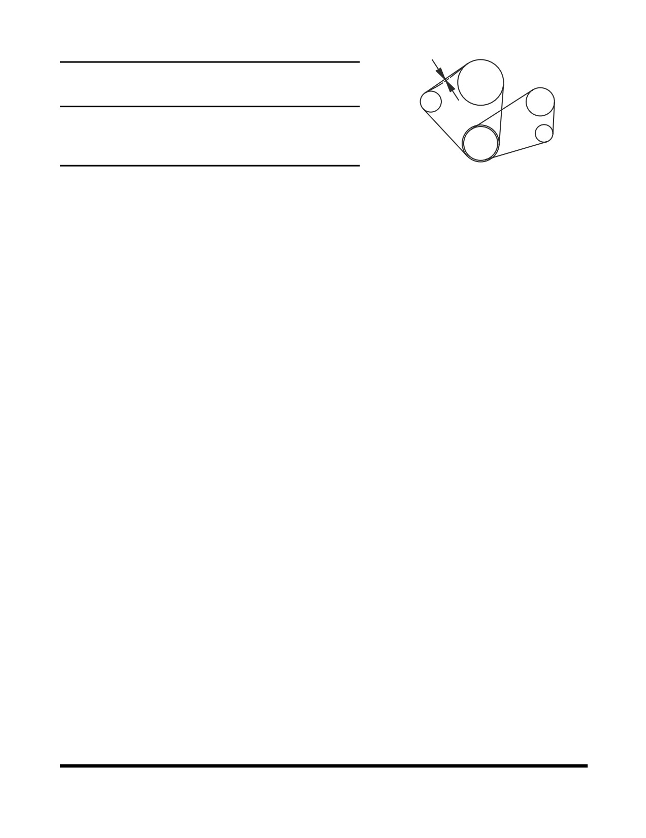
Check Engine Fan Belt Tension
FAN
10mm/10kg
COMPRESSOR
IMPORTANT
A loose fan belt can cause engine overheating, poor
ALTERNATOR
charging, and/or premature belt wear. A belt that is too tight
can cause damage to the water pump, alternator bearing or
belt.
CRANKSHAFT
FG000353
1.
Inspect every 250 hours. (Inspect after first 50 hours of
Figure 44
operation.)
2.
With the engine shut off, check the tension of the fan belt
by pressing downwards on the belt, midway between the
fan pulley and alternator pulley. The belt should flex
approximately 10 mm (0.4 in). See Figure 44. To adjust the
belt, loosen the alternator adjustment plate bolts, adjust the
belt tension and retighten the bolts.
Inspection, Maintenance and Adjustment
OP001005
4-29
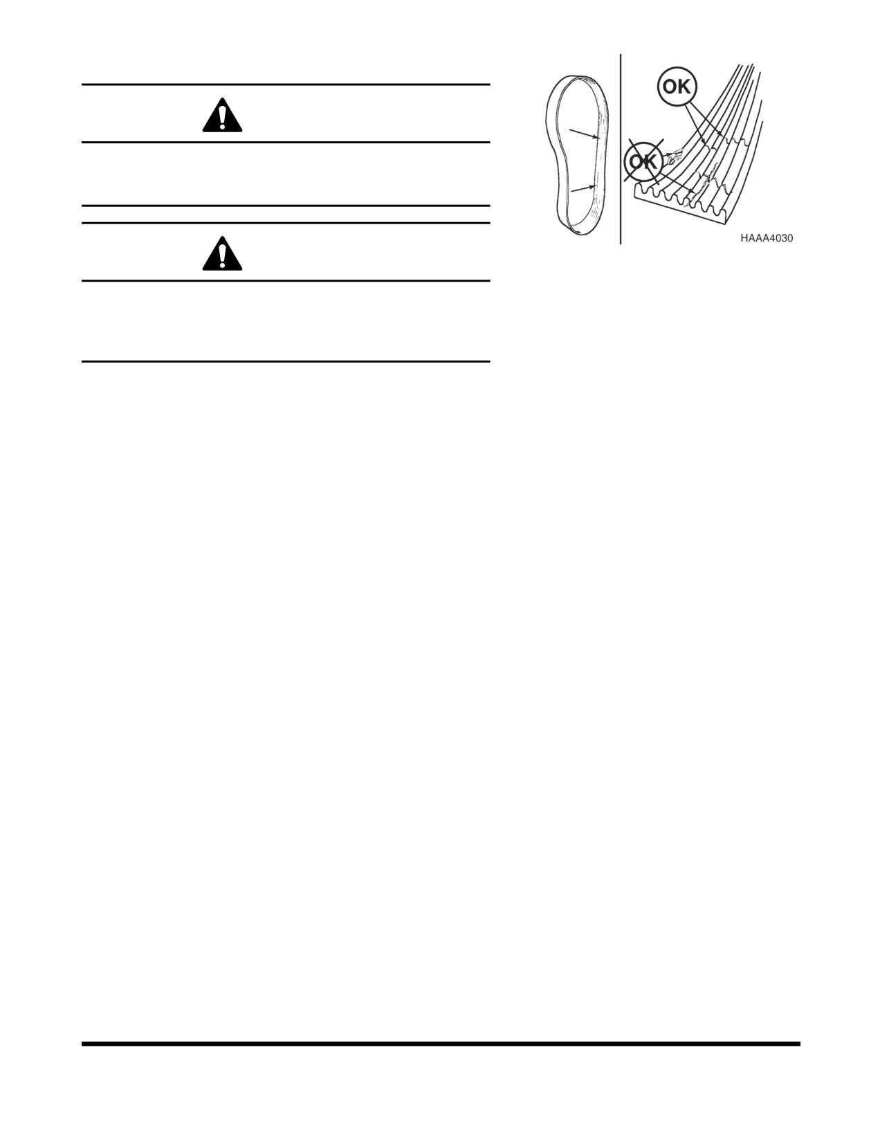
Check Engine Fan Belt Wear
WARNING
Keep clear of engine fan and fan drive belts when the
engine is running. Rotating fan and belt contact can cause
injury.
Figure 45
WARNING
When checking, adjusting or replacing drive belts, care
must be taken to prevent accidental cranking of the engine.
Be sure the starter switch is in the "OFF" position and the
controls are tagged.
1.
Replace badly worn, greasy or severely cracked belts
immediately. These conditions prevent proper belt
function. Visually inspect the belt. Check the belt for
intersecting cracks. Transverse
(across the belt width)
cracks are acceptable. Longitudinal
(direction of belt
length) cracks that intersect with transverse cracks are not
acceptable. Replace the belt if it is frayed or has pieces of
material missing.
2.
Before installing new belts, make sure all pulley grooves
are clean and not worn. Replace pulley, if damaged, or if
the grooves are worn.
3.
All pulley support bearings, shafts, and brackets must be in
working order.
4.
When replacing belts and pulleys, pulley alignment must
be checked with belts tensioned and brackets securely
clamped. A misalignment that can be detected by the
naked eye is detrimental to belt performance.
5.
Do not force the belts into the pulley grooves by prying with
a screwdriver or pry bar. This will damage the belt side
cords which will cause the belts to turn and result in
complete destruction of the belts in operation.
6.
Belts on new machines and replacement belts lose their
tension as they seat into the pulley grooves. Check the
tension of new belts at 50 hour intervals until tension is
stabilized and thereafter, every 250 hours. If the tension
falls below the required minimum, the belt slips damaging
the belts and pulley grooves.
NOTE: When operating in abrasive conditions, check
tension every 100 hours.
Inspection, Maintenance and Adjustment
OP001005
4-30
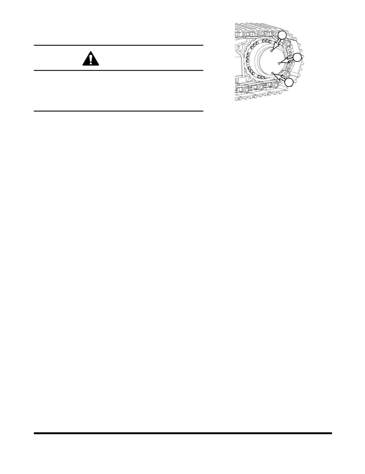
Check Oil Level in Travel Reduction
Device (One on Each Side of Unit)
3
1
WARNING
The gear oil is very hot after the machine has been
operating. Shut all systems down and allow them to cool.
2
Before fully removing any motor case inspection port plug,
etc., loosen the plug slightly to allow pressurized air to
FG000298
escape.
Figure 46
1.
Make sure that the machine is on firm, level ground.
2.
Rotate the track until ports (1 thru 3, Figure 46) are in their
proper positions as shown.
3.
Loosen fill plug (3, Figure 46) slightly to allow pressurized
air to escape.
4.
Remove oil level plug (1, Figure 46).
5.
Check oil level. The oil should be near the bottom of the
level plug opening.
6.
Add oil through the fill plug
(3, Figure
46) opening, if
necessary.
7.
Clean and install oil level and fill plugs (1 and 3, Figure 46).
8.
Repeat this procedure on the other travel reduction device.
Inspection, Maintenance and Adjustment
OP001005
4-31
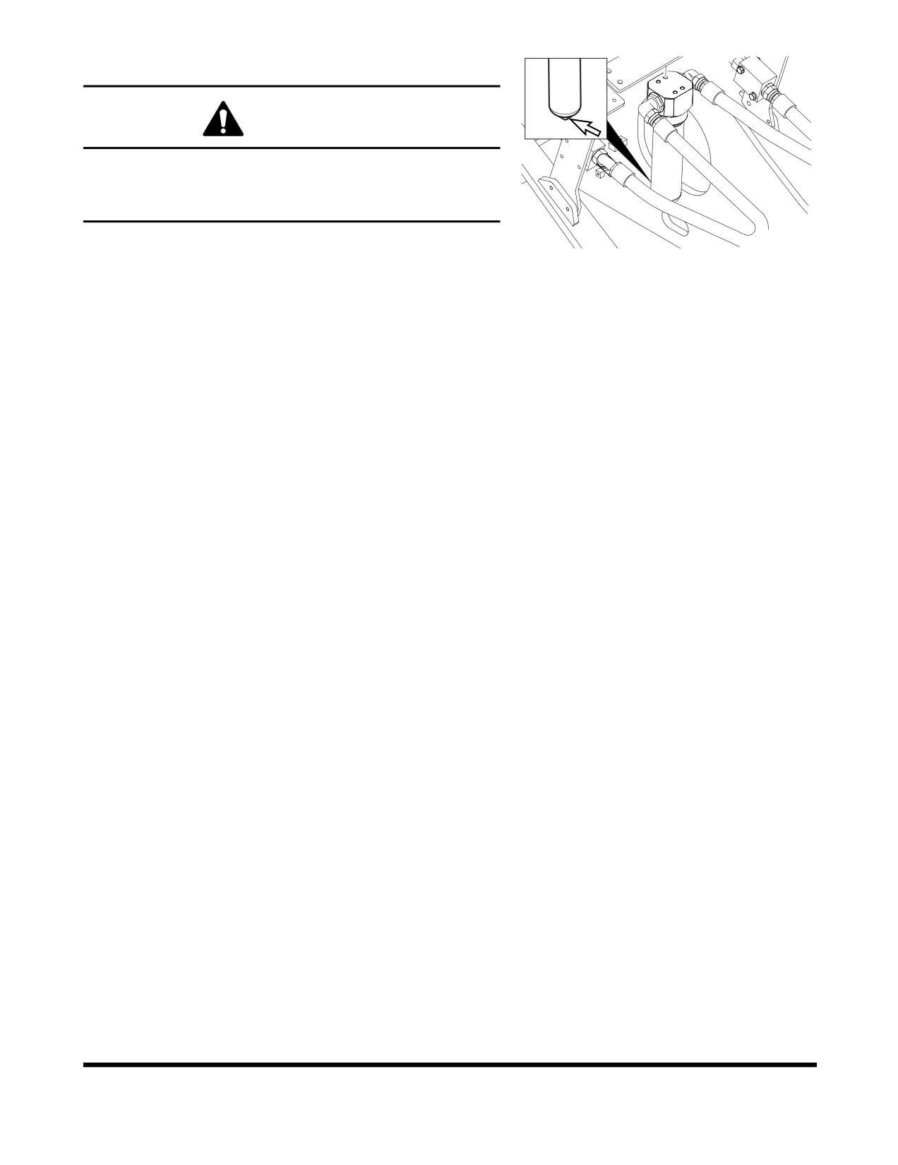
Change Breaker Filter Element (Optional)
WARNING
The hydraulic oil will be hot after normal machine
operation.
Allow the system to cool down before changing pilot filter.
FG000339
1.
Position the machine on firm, level ground. Lower the front
attachment to the ground and shut down engine.
Figure 47
2.
Loosen the hydraulic oil tank breather cap to release
pressure.
3.
Locate breaker filter assembly (Figure 47).
4.
Position a container under the filter assembly. Remove the
drain plug and completely drain the assembly.
5.
Using a 30 mm spanner, unscrew filter housing from filter
bottom.
6.
Remove O-ring from filter head.
7.
Replace filter.
8.
Apply a small amount of oil around the entire O-ring and
install the filter housing on the filter head.
NOTE: Tightening torque : 27 kg•m (265 Nm, 195 ft lb)
9.
Install drain plug in bottom of filter housing.
10. After changing breaker filter, vent air from pump and check
level of hydraulic oil tank.
Change Swing Reduction Device Oil (Drain
and Refill After First 250 Hours)
NOTE: Change swing reduction device oil after first
250
hours on a new machine and every 2,000 hours
thereafter (See page 4-49).
Change Oil in Travel Reduction Device
(One on Each Side of Unit) (After First
250 Hours)
NOTE: Drain and refill oil after first 250 hours of operation or
rebuild, and every 1,000 hours thereafter (See page
4-46).
Inspection, Maintenance and Adjustment
OP001005
4-32
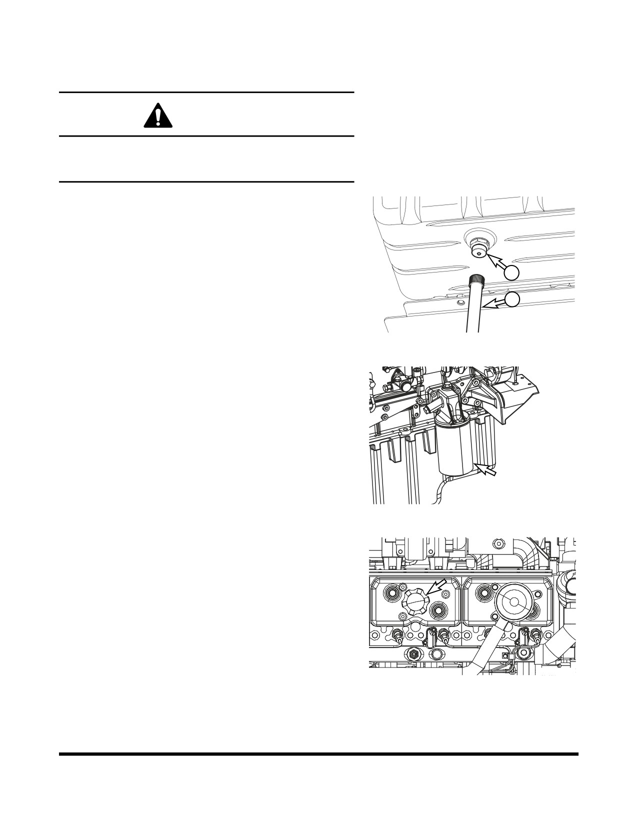
Change Engine Oil and Filter
NOTE: Change engine oil and filter after first 50 hours of
operation or rebuild, then every 500 thereafter.
WARNING
DO NOT change oil on a hot engine. Allow the engine to
cool down before attempting to change the engine oil and
filter to avoid burns by touching hot engine parts.
1.
Position a larger container under the engine. Remove cap
(1, Figure 48) and install hose (2) to drain the engine oil.
Remove hose (2) and install cap (1).
NOTE: Dispose of drained fluids according to local
regulations.
1
2
FG000144
Figure 48
2.
Replace engine oil filter by using filter wrench. The engine
oil filter is a spin-on type. See Figure 49. Remove and
discard filter.
3.
Install new filter. Apply a small amount of oil around filter
gasket. Screw filter on head until gasket contacts head,
turn filter 1/2 turn more.
FG015482
Figure 49
4.
Refill the engine with the correct oil through the oil fill port
(Figure 50). Refer to the Lubrication Table of this manual
for the recommended oil for the operating conditions.
NOTE: See
“Fluid Capacities” on page 4-8. for
capacity.
5.
Start engine. Run engine for five minutes at "LOW IDLE,"
and check engine oil pressure light.
6.
Shut down engine. Look for signs of leaks at filter. Recheck
oil level after fifteen minutes.
FG015483
Figure 50
Inspection, Maintenance and Adjustment
OP001005
4-33
Replace Hydraulic Oil Return Filter (After
First 250 Hours)
NOTE: Replace hydraulic oil return filter after first 250 hours
of operation or rebuild, then every
1,000 hours
thereafter (See page 4-44).
Change Pilot Filter (After First 250 Hours)
NOTE: Change pilot filter after first 250 hours and every
1,000 hours thereafter (See page 4-45).
Inspect Pins and Bushings of the Front
End Attachments for Signs of Wear
Check Fluid Levels in Batteries and
Battery Charge Levels
Inspect for Any Loose or Missing Nuts and
Bolts
Inspect Fuel System Hose Clamps
Inspection, Maintenance and Adjustment
OP001005
4-34
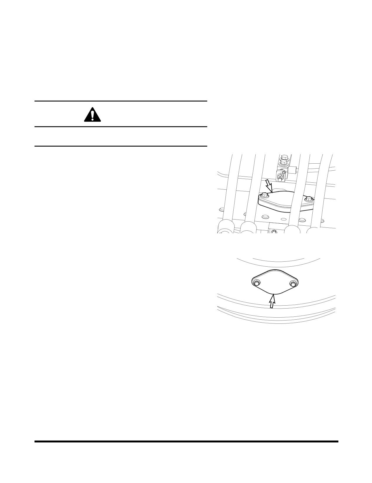
500 HOUR / 3 MONTH SERVICE
Perform All Daily, 50 and 250 Hour Service
Checks
Grease Swing Gear and Pinion
WARNING
Greasing swing gear and pinion must be serviced by only
one person.
1.
Remove inspection cover and inspect the condition of the
grease. Make sure that water or other contaminants are
not noticeable.
NOTE: The upper structure must be rotated a little at a
time so that the entire face of the swing gear
can be lubricated. Use extreme caution when
performing this operation.
FG000147
Figure 51
2.
If water or other contaminations are found, remove the
lower access cover so that the gear teeth can be
thoroughly cleaned and lubricated.
3.
Install access covers after lubricating gear teeth.
FG000148
Figure 52
Inspection, Maintenance and Adjustment
OP001005
4-35
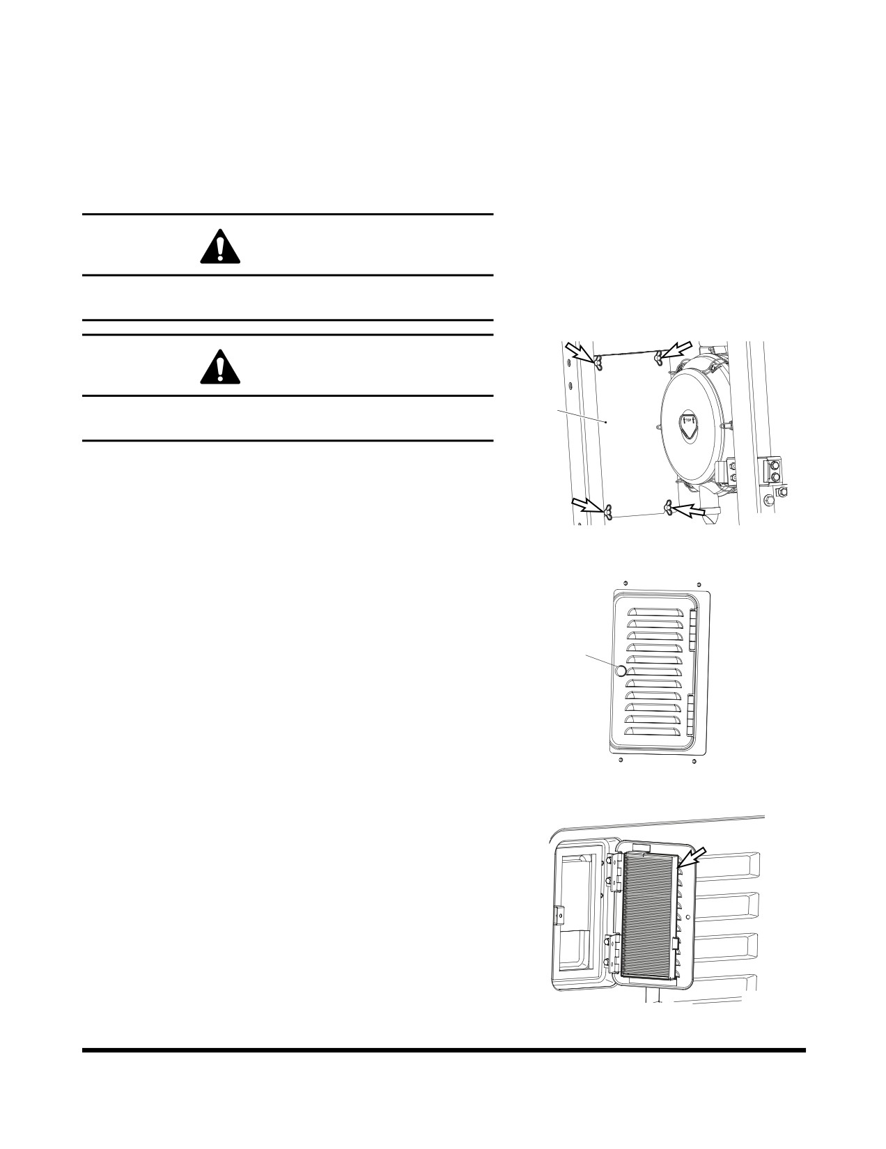
Clean Air-Conditioning Outer Filter
The unit is equipped with an air filtration system which filters out
dirt and dust particles from air being circulated into operator's
cabin. This filter should be cleaned out.
NOTE: In the event that the unit is being operated in a dusty
environment, the cleaning and replacement should
be performed more frequently. If filter is damaged,
replace damaged filter with a new one.
WARNING
All service and inspection of air-conditioning system should
be performed with the starter switch in the "O" (OFF) position.
WARNING
If using compressed air to clean the element, make sure
1
that proper eye protection is worn.
Donaldson.
NOTE: All right and left call outs are based on the operator
being seated in the operator's seat facing the front.
1.
Open the door in the left front of the machine, then remove
FG000440
the cover (1, Figure 53) by loosening the four wing bolts.
Figure 53
2.
Open the cover by turning the knob (1, Figure 54) in the
rear of the cabin.
1
FG000441
Figure 54
3.
Remove filter (Figure 55) and inspect for any damage.
4.
Use compressed air to clean filter. If filter is still dirty, then
change to new one.
5.
Reassemble in reverse order.
FG000342
Figure 55
Inspection, Maintenance and Adjustment
OP001005
4-36
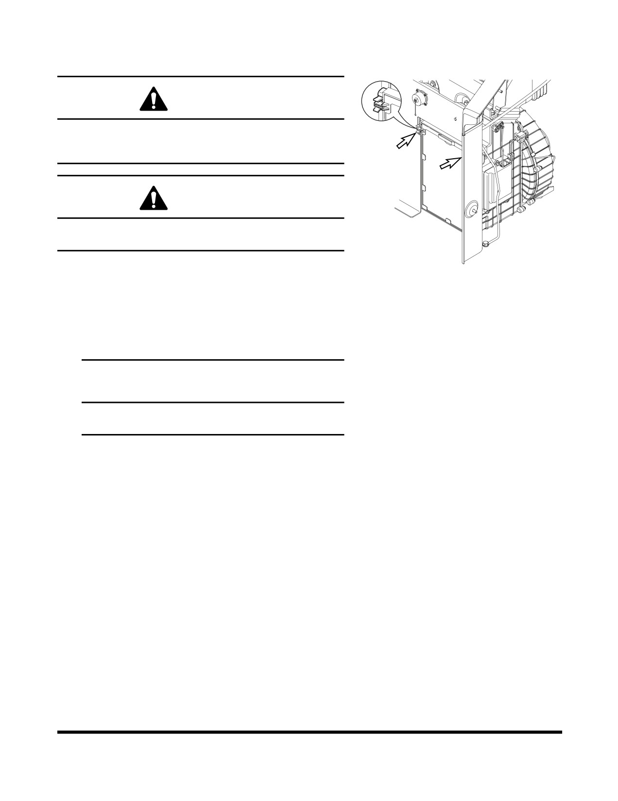
Check and Clean Air-Conditioning Inner
Filter
WARNING
All service and inspection of air-conditioning system
should be performed with the starter switch in the "O"
(OFF) position.
WARNING
If using compressed air to clean the element, make sure
that proper eye protection is worn.
FG000422
1.
Remove the filter by pulling out ward the knob while
Figure 56
pressing the upper part and lower part of the filter handle
which is inside of the left rear part of the cabin.
2.
Use compressed air in the clean filter. If the filter is
damaged replaced by a new one.
If the filter is very dirty use a mild soap or detergent and
water to clean it.
IMPORTANT
If water was used to clean filter, be certain it is
completely dry before installing.
Inspection, Maintenance and Adjustment
OP001005
4-37
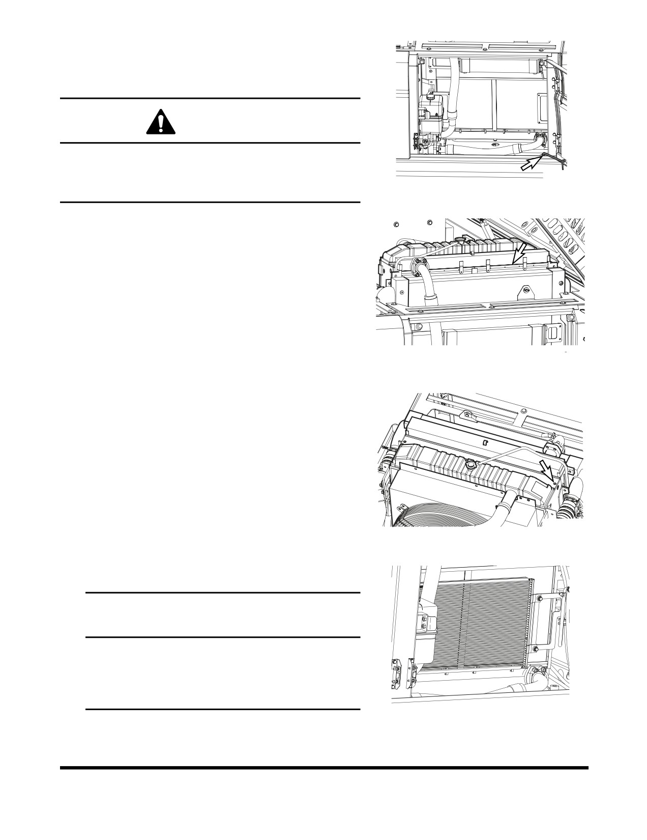
Clean Radiator, Oil Cooler, Intercooler,
Fuel Cooler and Air Conditioner
Condenser Core
WARNING
If compressed air, steam or water hit your body directly,
there is danger of injury. Always wear protective glasses,
FG000150
mask and safety shoes during the cleaning precess. Make
Figure 57
sure that all extra personnel are clear of the work area.
1.
Open the rear left door and engine cover.
2.
Loosen the wing bolt(s) and remove dust net from in front
of oil cooler and intercooler.
FG000151
Figure 58
3.
Remove wing bolts and plate (Figure 59) between radiator
and oil cooler.
4.
Clean the outside of the radiator and oil cooler, intercooler
and fuel cooler with compressed air, steam or water. Wash
from the outside of the engine compartment inwards.
Repeat the cleaning process from the inside of the engine
compartment outwards to remove all dirt and debris.
NOTE: Clean dust net and install it after cleaning
radiator, oil cooler, intercooler and fuel cooler.
FG000152
Figure 59
5.
Clean air conditioner condenser core with compressed air,
steam or water.
IMPORTANT
To prevent damage to the cores, apply compressed air
from an appropriated distance. Damaged core may
cause water leakage or overheating. In a dusty site,
check the core daily, irrespective of the maintenance
interval.
FG000153
Figure 60
Inspection, Maintenance and Adjustment
OP001005
4-38
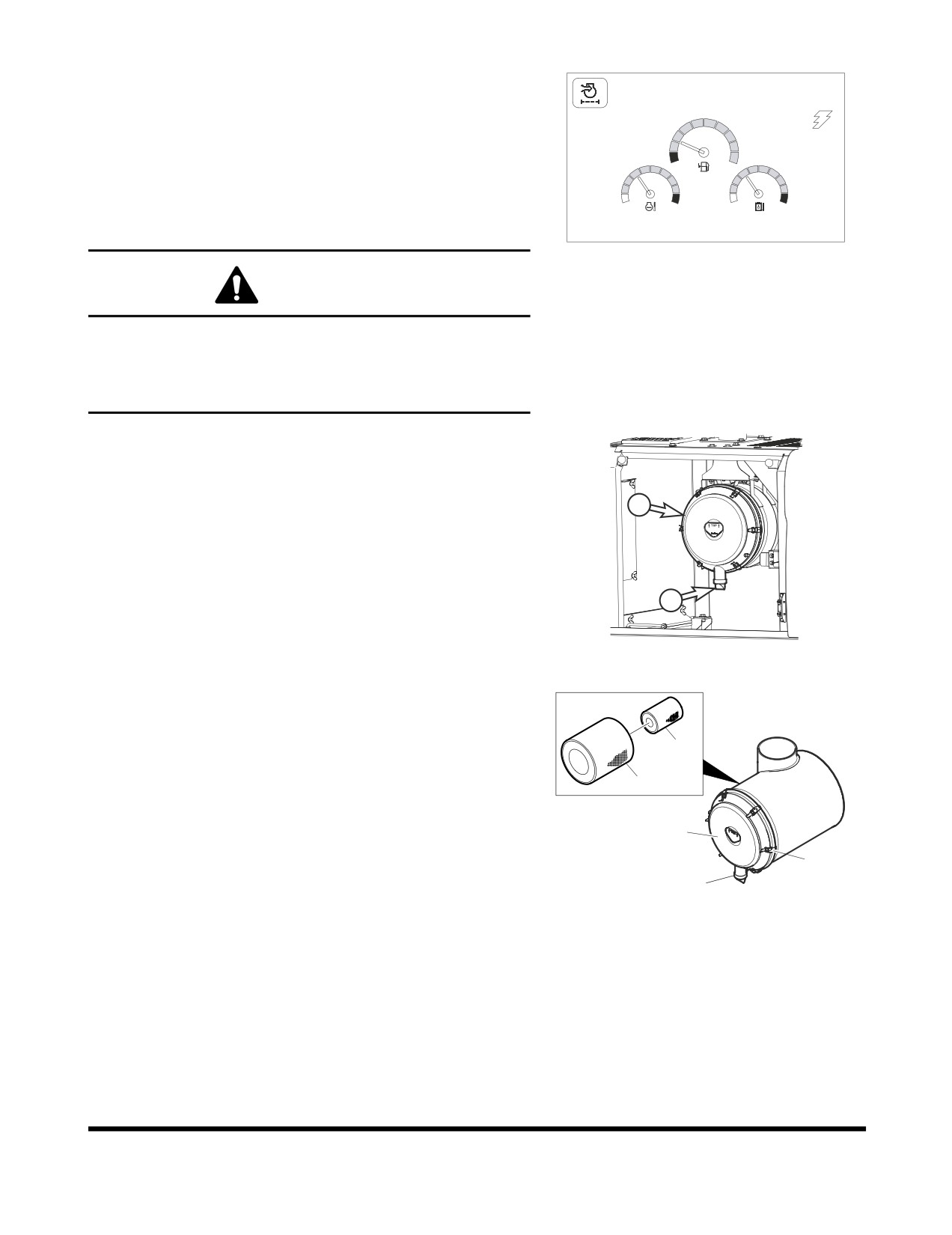
Clean Outer Filter of Air Cleaner
02/05 [MO] 11:30
NOTE: Clean outer filter every 500 hours / 3 months of
service.
NOTE: If air cleaner clogged warning light (Figure 61) on
instrument panel comes "ON" the air cleaner must be
E
F
serviced.
C
H
C
H
NOTE: When working in severely dusty conditions, the
service interval should be shortened.
E/G SPEED 1700 RPM
FG000264
Figure 61
WARNING
Never clean or attempt to remove the air cleaner filter if the
engine is running.
If using compressed air to clean the filter, make sure that
proper eye protection is worn.
1.
Locate the air cleaner assembly.
NOTE: When it reaches every 500 hours or If indicator
light
(Figure
61) on instrument panel comes
"ON" the air cleaner must be serviced.
2
NOTE: Replace outer filter after cleaning 5 times or
every 2,000 hours / 1 year of service.
2.
Remove and clean rubber evacuator valve (1, Figure 62)
from bottom of air cleaner housing cover (2). Inspect seal
1
lips for wear or damage. Replace valve if necessary.
FG000297
NOTE: Install evacuator valve with lips parallel to the
Figure 62
cover.
3.
Remove the access cover (2, Figure 63) by loosening the
latches (3).
4.
Remove the outer filter (4, Figure 63) from the housing. Do
5
not remove inner filter (5).
4
2
3
1
FG000702
Figure 63
Inspection, Maintenance and Adjustment
OP001005
4-39
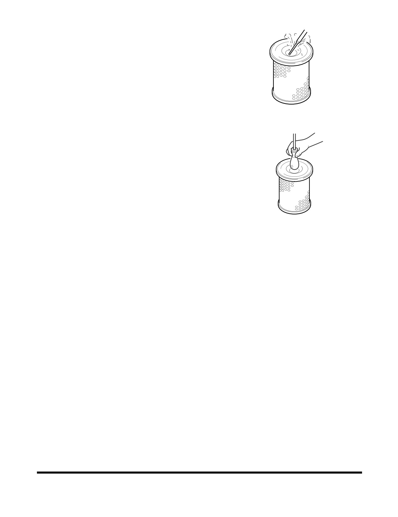
5.
Clean the outer filter (4, Figure 63) by blowing compressed
air from the inside of the filter towards the outside. Do not
use more than 205 kPa (30 psi) air pressure.
HAOC570L
Figure 64
6.
Check outer filter by shinning a light through it. If small
holes or thinner parts are found on the element after
cleaning it, replace the filter.
7.
Clean the inside of the air cleaner body and the inside of
the air cleaner cover. Do not use compressed air.
8.
Properly install the air filter and cover.
9.
After filter service be sure to install cover with arrows
pointing "UP."
NOTE: If after cleaning the outer filter, the air cleaner
FG000412
clogged indicator remains "ON," replace the
Figure 65
outer and inner filters. Do not clean inner filter.
Inspection, Maintenance and Adjustment
OP001005
4-40
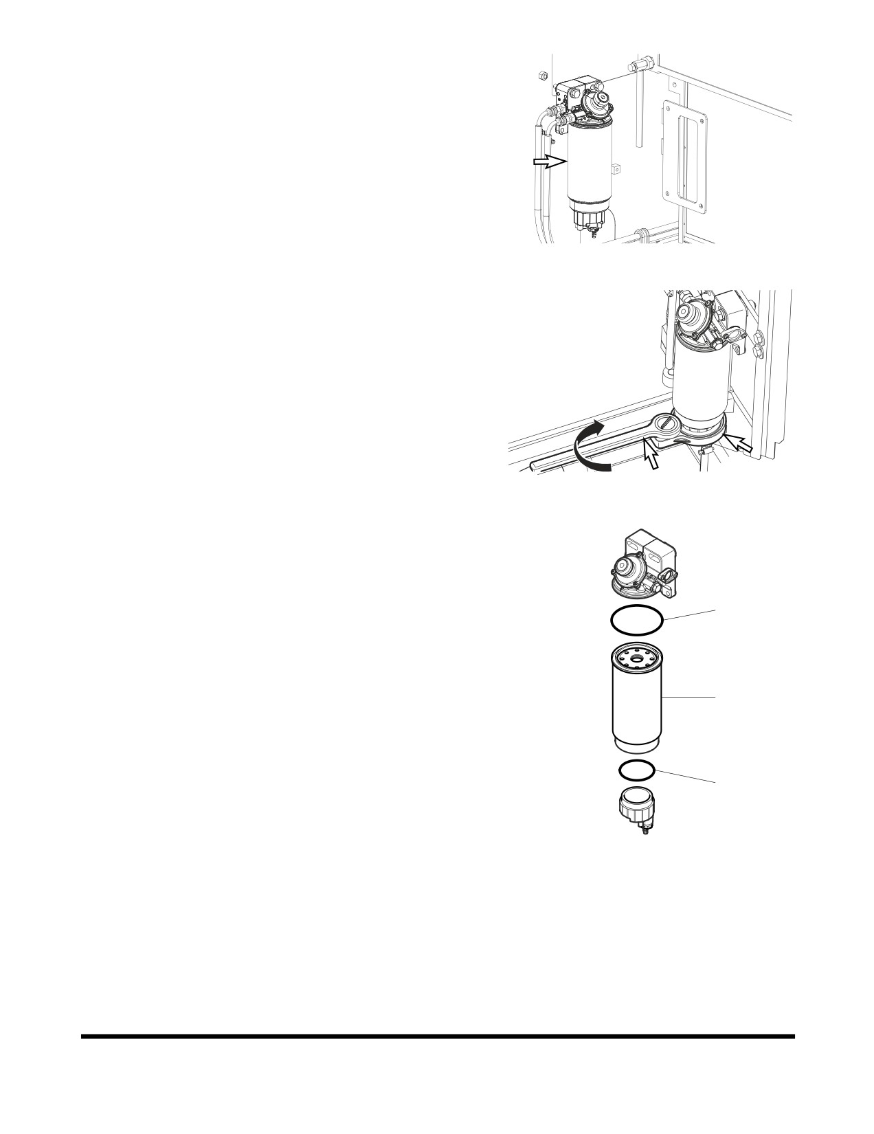
Change of Fuel Prefilter
1.
Open the left rear side door to access fuel prefilter.
2.
Position a small container under prefilter. Drain fuel by
opening drain valve on bottom of filter.
NOTE: Dispose of drained fluids according to local
regulations.
FG015484
Figure 66
3.
Remove the bowl using supplied tool.
4.
Remove the cartridge.
FG015485
Figure 67
5.
Coat surface of packing (2, Figure 68) with fuel on new
cartridge (1).
6.
Tighten the cartridge by hand until the packing comes into
contact with the surface of the filter housing head.
7.
When it reach the surface, tighten the cartridge about 3/4
2
of a turn more.
8.
Coat surface of seal (3, Figure 68) with fuel, and tighten
the bowl with tool.
1
3
FG000428
Figure 68
Inspection, Maintenance and Adjustment
OP001005
4-41
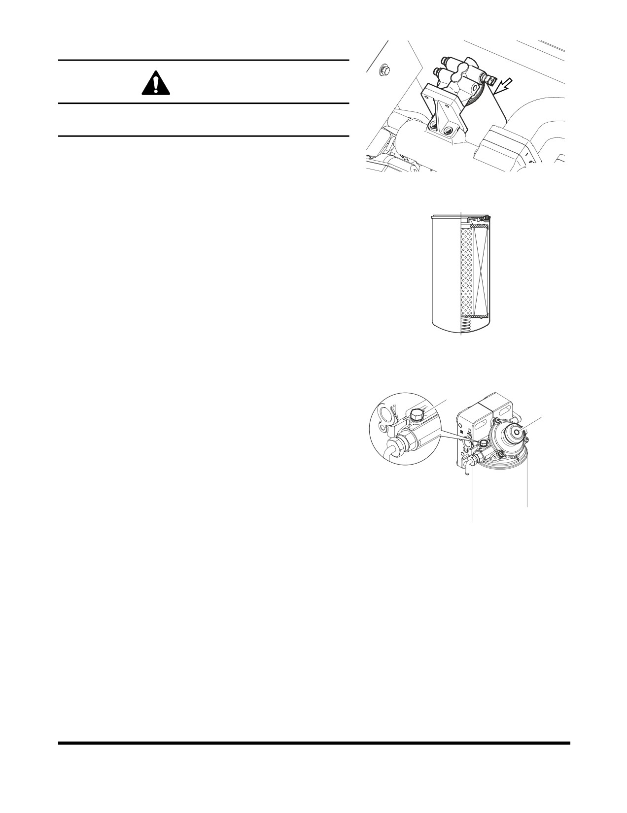
Change Fuel Filter
WARNING
Exchange filter after waiting for engine to cool. Be careful of
fire hazards. Do not smoke.
1.
Locate fuel filter inside engine compartment.
FG000154
2.
Position a small container under fuel filter.
Figure 69
3.
Unscrew fuel filter from head assembly. Discard fuel filter.
NOTE: Dispose of drained fluids according to local
regulations.
4.
After cleaning filter head, install new fuel filter. Screw filter
on head until gasket contacts head, and turn filter 1/2 turn
more with a filter wrench.
NOTE: Coat fuel filter gasket with fuel.
NOTE: Fill fuel filter with clean fuel. This will help
reduce fuel system priming.
FG000478
Figure 70
Fuel System Priming
1
If air remains in the fuel inlet line to the engine, it may cause the
2
engine to run in an abnormal condition. Air may impact the
starting capability of the engine, and may also result in surging
engine speeds.
If the machine happens to have run out of fuel, or if the fuel filter
has been replaced, air may need to be bleed using the following
procedure:
1.
Shut down engine.
FG000431
2.
Loosen plug (1, Figure 71) on the fuel prefilter head.
Figure 71
3.
Pump the hand operated primer pump (2, Figure 71) on the
fuel prefilter. Pump primer until fuel is present at plug hole
in fuel prefilter head.
4.
Tighten plug (1, Figure 71) in fuel prefilter head.
5.
Continue to pump primer pump until a strong resistance is
felt.
6.
Start engine and look for signs of leaks.
7.
Repeat procedure if necessary.
Inspection, Maintenance and Adjustment
OP001005
4-42
1,000 HOUR / 6 MONTH SERVICE
Perform All Daily, 50, 250 and 500 Hour
Service Checks
Grease Swing Reduction Device
1.
Position the machine on firm, level ground. Lower the front
attachment to the ground and shut down engine.
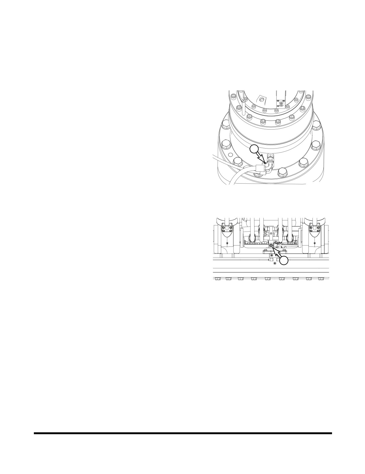
2.
Remove air vent plug (1, Figure 72) from swing reduction
device.
1
FG000439
Figure 72
3.
Press grease fitting and inject grease with the grease gun
on the marked point (2, Figure 73).
4.
Install air vent plug
(1, Figure
72) in swing reduction
device.
2
FG000156
Figure 73
Inspection, Maintenance and Adjustment
OP001005
4-43
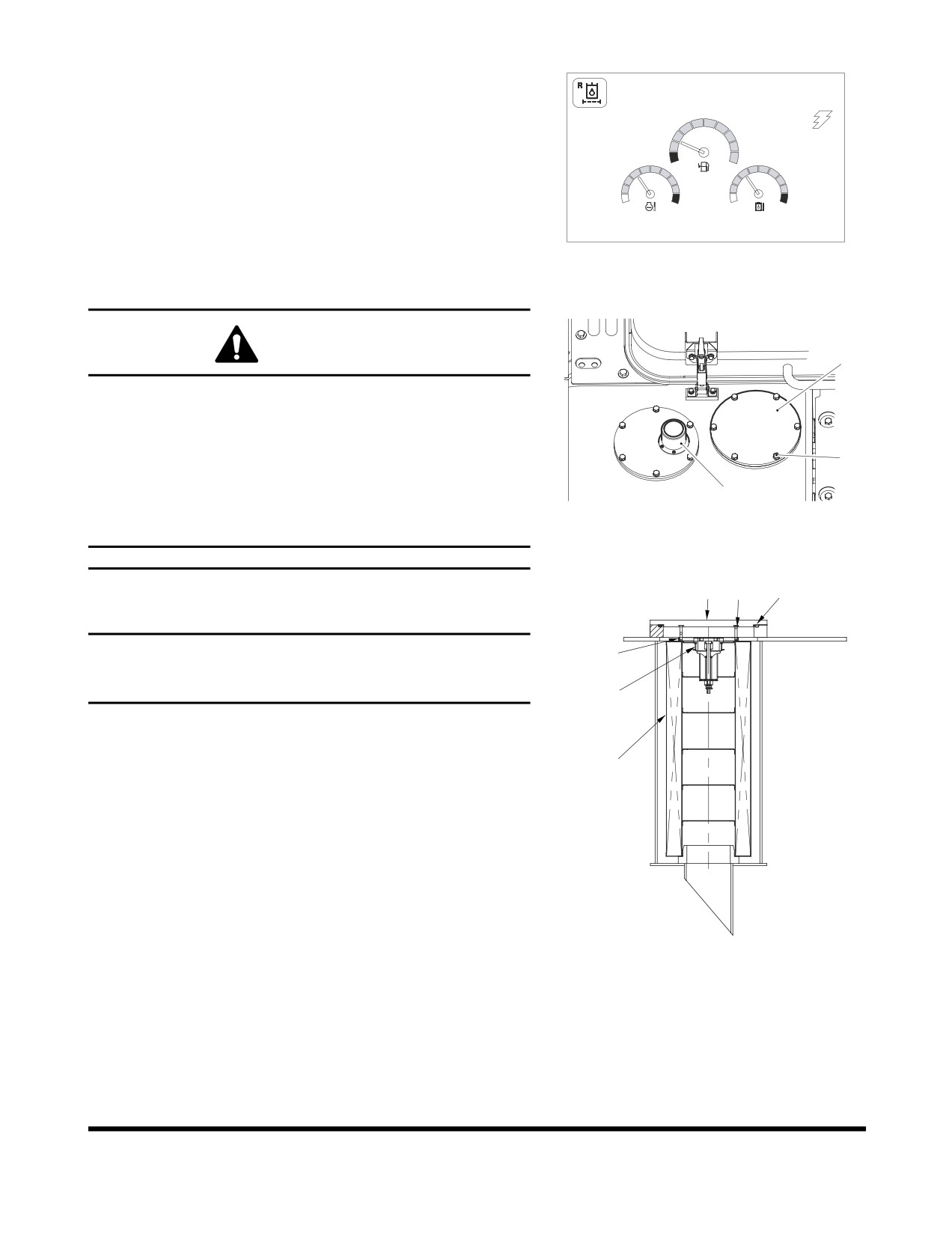
Replace Hydraulic Oil Return Filter
02/05 [MO] 11:30
NOTE: Change hydraulic oil return filter after first 250 hours
of operation or rebuild, and every
1,000 hours
thereafter.
NOTE: If return filter clogged warning light (Figure 74) on
E
F
instrument panel comes "ON" the return filter must be
serviced.
C
H
C
H
E/G SPEED 1700 RPM
FG000760
Figure 74
WARNING
3
The hydraulic oil will be hot after normal machine
operation. Allow the system to cool before attempting to
service any of the hydraulic components.
The hydraulic tank is pressurized. Lift the hydraulic
2
breather cap slightly to allow the pressurized air to vent.
After the pressure has been released, it is safe to remove
1
either the fill cap or service covers or drain water from the
FG000424
tank.
Figure 75
3
4
6
IMPORTANT
Make sure to clean any dirt or water from the top of the
7
hydraulic tank, especially around the fill port and filter
ports.
5
1.
Position the machine on firm, level ground. Lower the front
attachment to the ground and shut down engine.
8
2.
Lift the breather cap (1, Figure 75) slightly to release the
internal pressure.
3.
Remove bolts
(2, Figure
75) and service cover
(3).
Remove spring (4), valve
(5) O-ring
(6), and bypass
strainer (7), and then filter (8).
4.
Remove filter and discard.
NOTE: Used filter should always be disposed of
according to local regulations.
FG000761
Figure 76
5.
Install new filter and a new O-ring. Install bypass strainer,
valve and spring. Install service cover plate.
6.
Run engine for ten minutes at low idle to purge air from
circuit.
7.
Check level in hydraulic oil tank (See page 4-15). Add oil if
necessary.
Inspection, Maintenance and Adjustment
OP001005
4-44
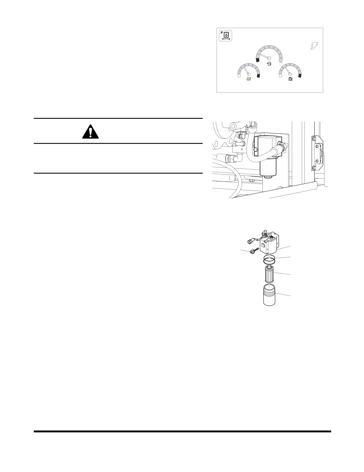
Change Pilot Filter
02/05 [MO] 11:30
NOTE: Change pilot filter after first 250 hours of operation or
rebuild, and every 1,000 hours thereafter.
NOTE: If pilot filter clogged warning light
(Figure
77) on
instrument panel comes "ON" the pilot filter must be
E
F
serviced.
C
H
C
H
E/G SPEED 1700 RPM
FG000763
Figure 77
WARNING
The hydraulic oil will be hot after normal machine
operation.
Allow the system to cool down before changing pilot filter.
1.
Position the machine on firm, level ground. Lower the front
attachment to the ground and shut down engine.
FG000149
2.
Lift the breather cap (1, Figure 75) slightly to release the
Figure 78
internal pressure.
3.
Locate pilot system filter assembly. See Figure 78.
4.
Unscrew canister (5, Figure 79) and remove O-ring (3) and
filter cartridge (4).
1
NOTE: The canister will be filled with oil. Use caution
2
when removing this assembly.
3
5.
Insert a new filter cartridge and O-ring. Apply a small
amount of oil around the entire O-ring and install the
4
canister assembly onto the filter head (1, Figure 79).
NOTE: Used filter should always be disposed of
according to local regulations.
5
FG000323
6.
After changing pilot filter, vent air from pump and check
Figure 79
level of hydraulic oil tank.
Inspection, Maintenance and Adjustment
OP001005
4-45
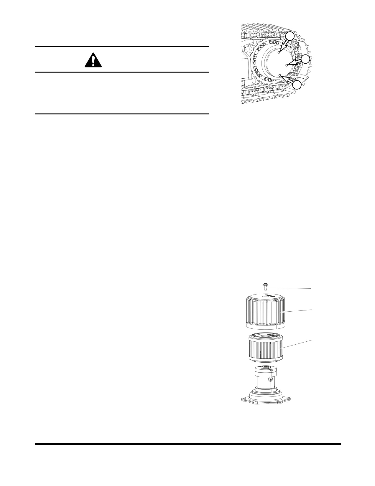
Change Oil in Travel Reduction Device
(One on Each Side of Unit)
3
1
WARNING
The gear oil is very hot after the machine has been
operating. Shut all systems down and allow them to cool.
2
Before fully removing any motor case, inspection port plug,
etc., loosen the plug slightly to allow pressurized air to
FG000298
escape.
Figure 80
NOTE: Drain oil after first 250 hours of operation or rebuild,
and every 1,000 hours thereafter.
1.
Make sure that the machine is on firm, level ground.
2.
Rotate the track until ports (1 thru 3, Figure 80) are in their
proper positions as shown.
3.
Place a container under drain plug (2, Figure
80) and
remove plugs (1 thru 3) to drain the travel reduction gear
oil.
NOTE: Dispose of drained fluids according to local
regulations.
4.
Install drain plug (2, Figure 80). Refill the travel reduction
gear case with fluid through fill port (3) until the fluid level is
at port (1). Install level plug (1) and fill plug (3).
NOTE: See
“Fluid Capacities” on page 4-8. for
capacity.
5.
Repeat this procedure on the other travel reduction device.
Change Air Breather Filter
1
1.
Position the machine on firm, level ground. Lower the front
attachment to the ground and shut down engine.
2
2.
Lift the breather cap(2. Figure 81) slightly to release the
internal pressure.
3.
Unscrew the bolt (1, Figure 81) and take off the breather
cap (2, Figure 81).
3
4.
Change a filter cartridge (3, Figure 81) and assemble the
breather cap by tighting the bolt.
NOTE: Used filter should always be disposed of
according to local regulations.
FG013207
Figure 81
Inspection, Maintenance and Adjustment
OP001005
4-46
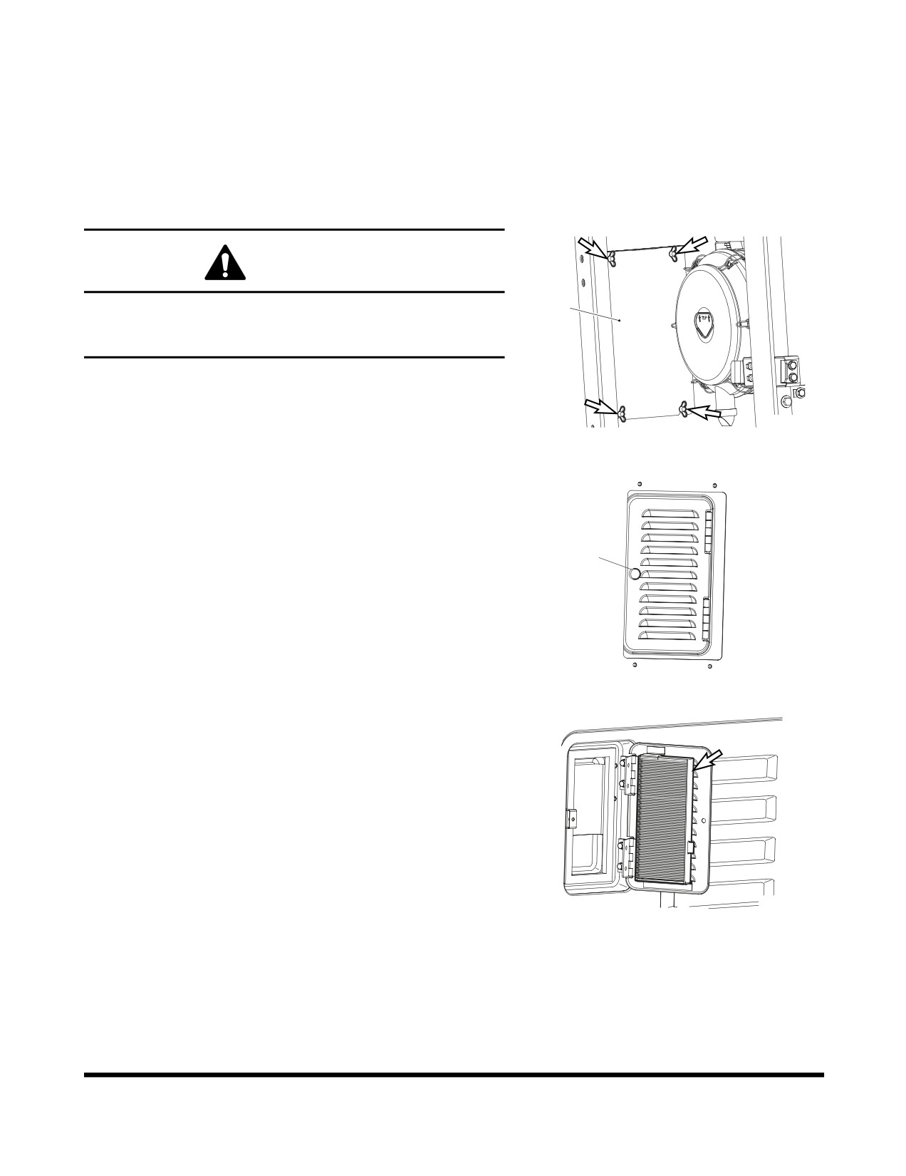
Change Air-Conditioning Outer Filter
The unit is equipped with an air filtration system which filters out
dirt and dust particles from air being circulated into operator's
cabin. This filter should be cleaned out.
NOTE: In the event that the unit is being operated in a dusty
environment, the cleaning and replacement should
be performed more frequently. If filter is damaged,
replace damaged filter with a new one.
WARNING
All service and inspection of air-conditioning system
1
should be performed with the starter switch in the "O"
Donaldson.
(OFF) position.
NOTE: All right and left call outs are based on the operator
being seated in the operator's seat facing the front.
FG000440
1.
Open the door in the left front of the machine, then remove
four wing bolts and washers, and access cover (1, Figure 82).
Figure 82
2.
Open the cover by unscrewing the knob (1, Figure 83) in
the rear of the cabin.
1
FG000441
Figure 83
3.
Remove filter (Figure 84) and replace with new one.
4.
Reassemble in reverse order.
FG000342
Figure 84
Inspection, Maintenance and Adjustment
OP001005
4-47
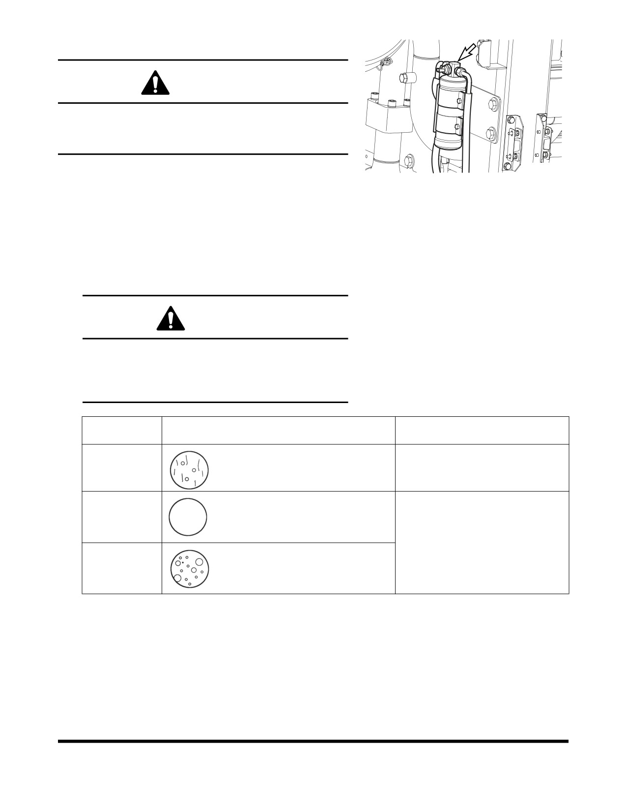
Check Air Conditioner Refrigerant
WARNING
Mixing of tobacco smoke and freon is deadly.
Do not smoke while servicing or recharging
air-conditioning system.
1.
Run engine at about 1800 rpm. Operate for a minimum of
FG000157
ten minutes to stabilize the system.
Figure 85
2.
Press the "HI" fan speed switch to set maximum air flow.
3.
Put the temperature control switch in maximum cooling
position.
4.
Press the "Internal Air Circulation" switch.
5.
Compare the flow of bubbles in the sight glass of receiver
dryer with the drawings in the following table.
CAUTION
Overfilling refrigerant may cause dangerous
high-pressure and poor cooling action; and low
refrigerant level may cause compressor damage.
Always maintain refrigerant at normal level.
Amount of
Appearance of the Sight Glass
Solutions
Refrigerant
Almost clear.
Normal
Any bubbles disappear.
Charge or withdraw the system with
the correct amount of HFC-134a
High
No bubbles are seen.
refrigerant.
Low
A flow of bubbles is visible.
Check and Adjust Engine **
Contact your nearest DOOSAN dealer.
Engine dealer for checking and adjusting the following items:
•
Engine Compression Pressure.
•
Injection Pressure.
•
Injection Timing.
Inspection, Maintenance and Adjustment
OP001005
4-48
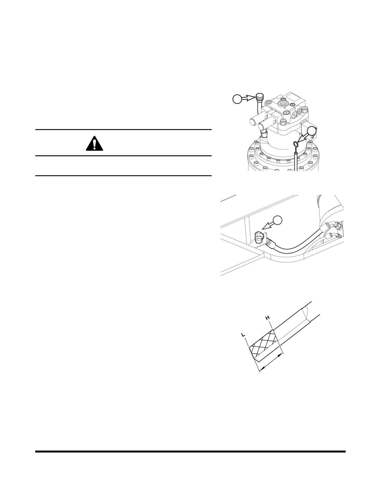
2,000 HOUR / YEARLY SERVICE
Perform All Daily, 50, 250, 500 and 1,000
Hour Service Checks
Change Swing Reduction Device Oil
2
NOTE: Change swing reduction device oil after first
250
hours of operation or rebuild and every 2,000 hours
thereafter.
1
WARNING
The gear oil is very hot after the machine has been
operating. Shut all systems down and allow them to cool.
FG000133
Figure 86
1.
Set a container under excavator.
2.
Release the drain plug (3, Figure 87) and drain the swing
reduction device oil into a container.
3
NOTE: Dispose of drained fluids according to local
regulations.
3.
After draining oil, tighten the drain plug.
FG014340
Figure 87
4.
Remove breather/fill cap (2, Figure 86) and add oil to "H"
mark on dipstick (1).
FG000419
Figure 88
Inspection, Maintenance and Adjustment
OP001005
4-49
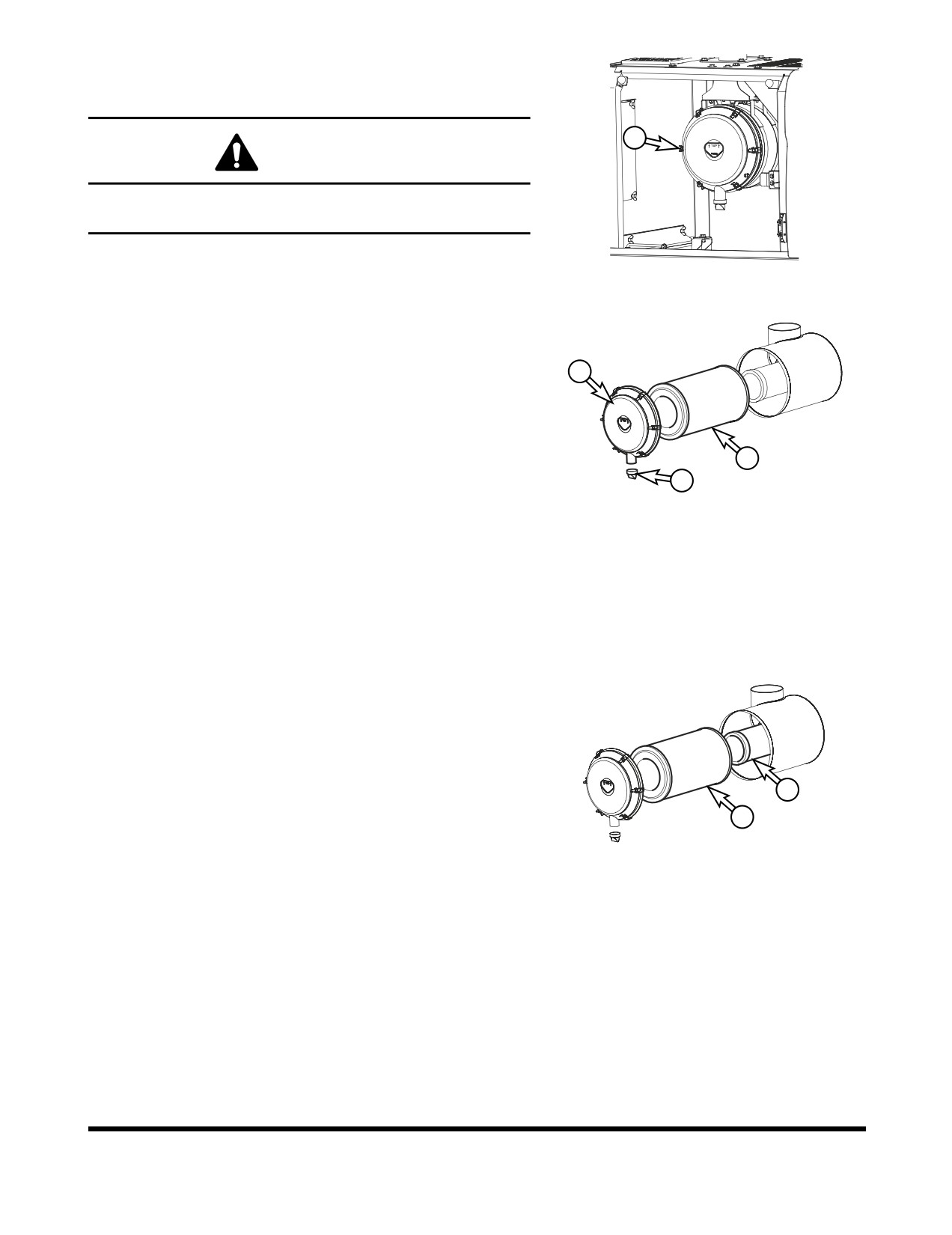
Replace Outer and Inner Air Cleaner
Elements
3
WARNING
Never clean or attempt to remove the air cleaner element if
the engine is running.
FG000414
NOTE: Replace outer element after cleaning 5 times or every
2,000 hours of service.
Figure 89
NOTE: Replace inner element whenever a new outer
element is installed.
If there is clogged filter signal on the gauge panel, use the
2
following procedure.
1.
Open the access door at the rear of the cabin.
2.
Remove the evacuator valve (1, Figure 90) and air cleaner
cover (2).
4
NOTE: Inspect evacuator valve seal lips for wear or
1
damage. Replace valve if necessary. Install
FG000425
evacuator valve with lips parallel to the cover.
Figure 90
3.
Remove outer filter (4, Figure 90) from the air cleaner
housing.
4.
Clean the air cleaner cover and the inside of the air cleaner
housing.
5.
Remove inner filter (5, Figure 91).
6.
Clean out inside of air cleaner housing. Do not use
compressed air to blow out housing.
7.
Install new inner filter. Do not clean and reuse inner
element.
8.
Install new outer filter.
9.
Install air cleaner cover and evacuator valve.
5
NOTE: Make sure that all gaskets and cover are
4
properly installed and seated.
FG000426
Figure 91
Inspection, Maintenance and Adjustment
OP001005
4-50
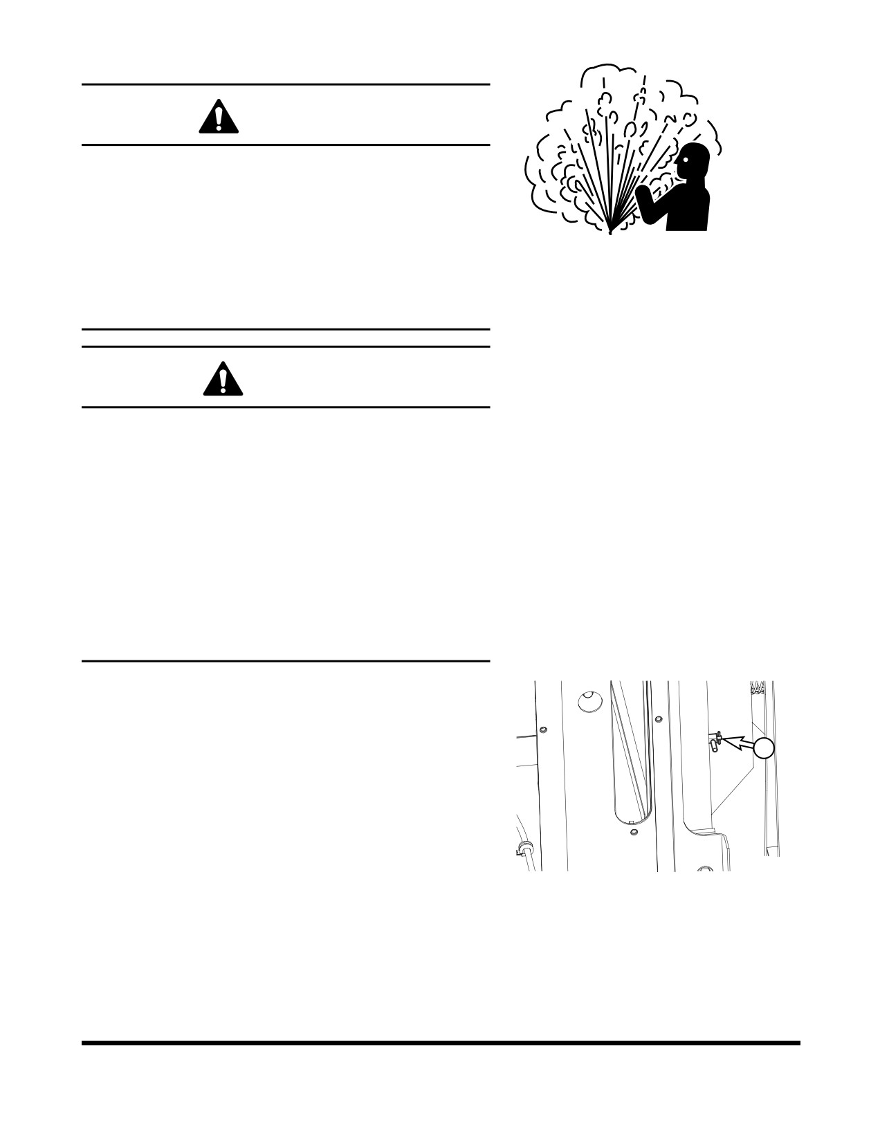
Change Radiator Coolant
WARNING
Allow the engine to cool before releasing the radiator cap.
Make sure to loosen the cap slowly to release any
remaining pressure.
Radiator cleaning is performed while the engine is running.
Take extreme caution when working on or near a running
ARO1760L
engine. Make sure to lock out and tag the controls notifying
Figure 92
personnel that service work is being performed.
Do not remove the radiator cap unless it is required.
Observe the coolant level in the coolant recovery tank.
CAUTION
Do not mix ethylene glycol and propylene glycol when
changing the antifreeze solution. Flushing should be
performed to minimize volume of mixing between the two
columns. Mixing the two compounds may cause generation
of foreign material to damage the system.
Do not mix antifreeze solutions from different
manufactures. Mixed solution may degrade the capabilities
of the system. It is recommended to use the standard
product from Doosan.
In the bitterly cold area or weather, the customer should
frequently check the performance of the coolant for
appropriateness for the weather, and then determine
change cycle of the coolant.
1.
Slowly open the radiator cap to allow any pressure to
escape.
2.
Place a container under the radiator and open the drain
valve (2, Figure 93).
2
NOTE: Dispose of drained fluids according to local
regulations.
FG000319
Figure 93
Inspection, Maintenance and Adjustment
OP001005
4-51
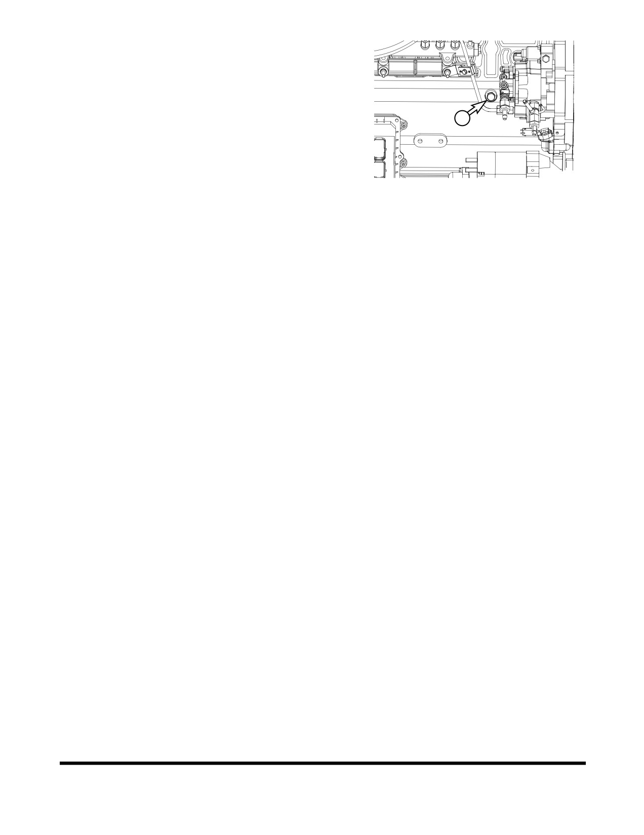
3.
Remove coolant drain plug (1, Figure 94) from engine.
4.
Install drain plug, and close drain valve after coolant has
completely drained from system.
5.
Fill cooling system with a flushing solution.
6.
Run engine at low idle until the coolant temperature gauge
1
reaches the "BLUE ZONE." Run engine for another ten
minutes.
7.
Allow engine to cool.
8.
Drain flushing fluid and fill system with water.
FG000322
Figure 94
9.
Run engine again to allow water to completely circulate.
10. After allowing engine to cool, drain water and fill system
with proper antifreeze mixture for ambient temperature.
Refer to coolant concentration table. See
“Antifreeze
Concentration Tables” on page 4-77.
11. Run engine without radiator cap installed, so that all air will
be purged from system. Fill radiator to fill neck.
12. Drain and fill radiator coolant recovery tank.
Inspection, Maintenance and Adjustment
OP001005
4-52
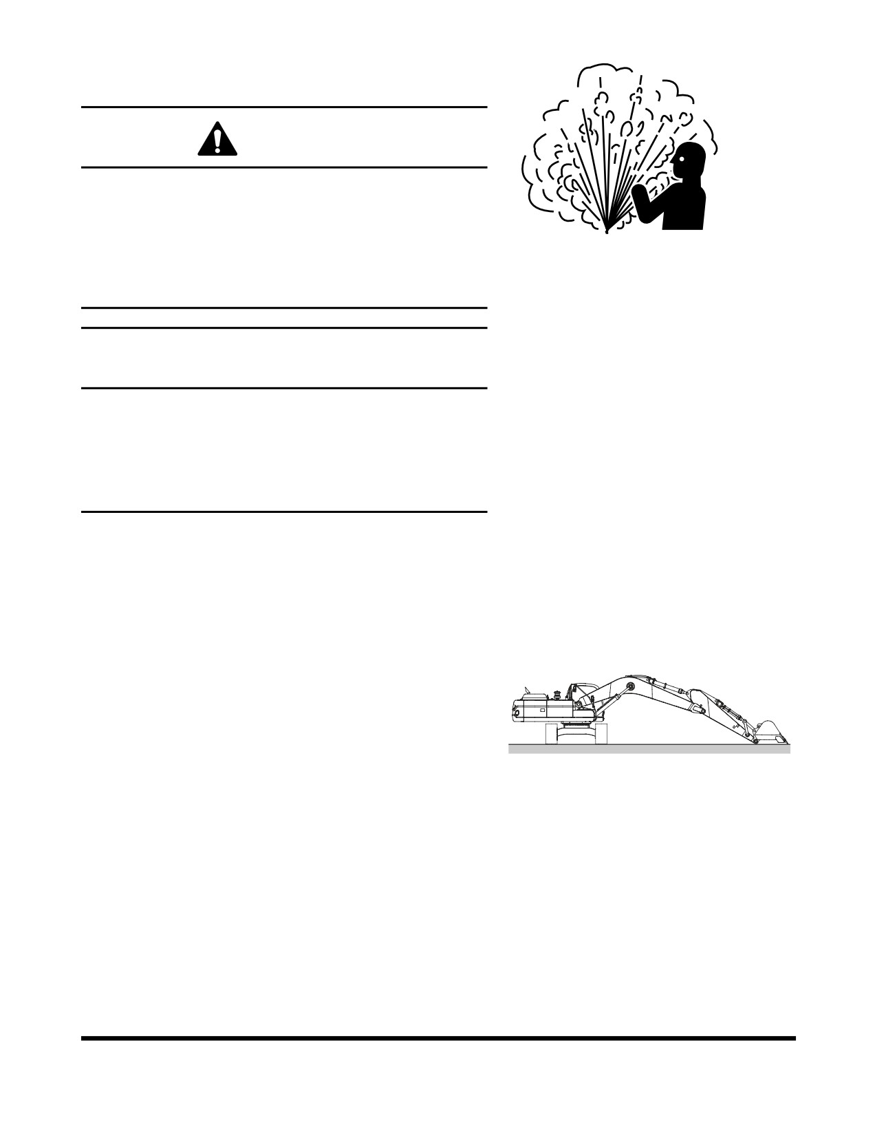
Hydraulic Oil Exchange and Suction
Strainer Cleaning
WARNING
The hydraulic oil will be hot after normal machine
operation. Allow the system to cool before attempting to
service any of the hydraulic components.
ARO1760L
The hydraulic tank is pressurized. Lift the breather cap to
Figure 95
allow the pressurized air to vent. After the pressure has
been released, it is safe to remove either the fill cap or
service covers.
IMPORTANT
Make sure to clean any dirt or water from the top of the
hydraulic tank, especially around the fill port and filter
ports.
Hydraulic oil change interval is 2,000 hours, only when
DOOSAN Genuine Oil is used. If another brand of oil is
used, guaranteed change interval is 1,000 hours.
NOTE: Based on the type of excavating being completed,
the working conditions (extremely hot or dusty) and
the extra front end attachments being used (hydraulic
breaker, etc.), the hydraulic fluid will need to be
changed more frequently.
1.
Position the machine on firm, level ground. Swing upper
structure perpendicular (90°) to tracks. Lower boom and
position bucket on ground as shown in Figure 96.
2.
Set safety lever on "LOCK" position.
3.
Shut down engine.
4.
Release pressurized air from hydraulic tank by lifting
breather cap (1, Figure 99).
FG000356
Figure 96
Inspection, Maintenance and Adjustment
OP001005
4-53
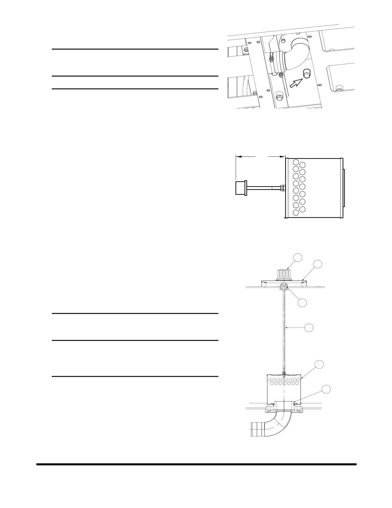
5.
Drain hydraulic oil from tank into a container capable of
holding 280 liters (74 U.S. gal.). After draining tank, install
drain plug.
IMPORTANT
Be careful of squirting oil when removing drain plug.
NOTE: Used filter and used oil should always be
disposed of according to local regulations.
FG014339
Figure 97
6.
Carefully remove bolts and cover (2, Figure 99) from top of
hydraulic oil tank. There is a spring (3) under the cover that
will force the cover up.
7.
Remove spring (3, Figure 99) and strainer (5), by pulling on
rod (4).
A
8.
Clean inside and outside of strainer. Replace strainer if it is
broken.
9.
Position strainer (5, Figure 99) on boss portion of suction
pipe (6).
NOTE: Measurement "A" is 612.5 mm (24.11 in).
HAOC411L
Figure 98
10.
Fill the hydraulic oil tank. Check level using sight gauge on
side of tank.
1
2
11.
Place spring (3, Figure 99) on rod (4) and assemble cover
(2).
12.
After replacing and cleaning the hydraulic oil, filter and
strainer, vent the system. See
“Venting and Priming
3
Hydraulic System” on page 4-83.
IMPORTANT
4
When the hydraulic breaker is being used, due to the
higher heat generated by this unit, use replacement
intervals recommended under the “Hydraulic Oil and
5
Filter Service Intervals” on page 3-36.
13.
Check level of hydraulic oil tank. (See page 4-15)
6
ARO1720L
Figure 99
Inspection, Maintenance and Adjustment
OP001005
4-54
Check Alternator and Starter**
**These checks need to be completed by an authorized
DOOSAN dealer.
Check All Rubber Antivibration Shock
Mounts
Perform and Record the Results of the
Cycle Time Tests
Inspect Machine to Check for Cracked or
Broken Welds or other Structural
Damage
Check, Adjust Valve Clearance **
Check Head Bolt Torques
Inspection, Maintenance and Adjustment
OP001005
4-55
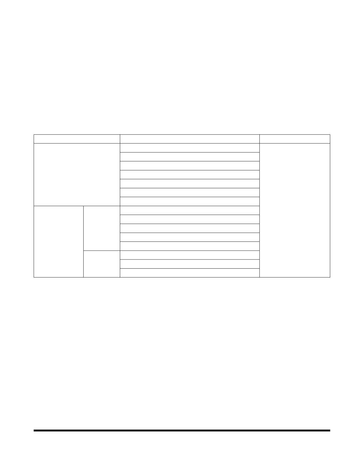
4,000 HOUR / BIENNIAL
SERVICE
Major Parts - Periodic Replacement
To ensure safe operation and work, perform periodic
inspections. Also, to increase safety, replace the following parts.
These parts are the ones most often subjected to abrasion, heat
and fatigue. Exchange these parts with new ones at the
designated time intervals, even if the old parts look good.
Always replace all related parts such as gaskets and O-rings.
Use only original equipment manufacturers parts.
Major Component
Parts Name to be Exchanged Periodically
Time to Exchange
Engine
Fuel hose (Tank to fuel prefilter)
Fuel hose (Fuel prefilter to fuel cooler)
Fuel hose (Fuel cooler to ECU)
Fuel hose (Tank to CP pump)
Heater hose (Heater to engine)
Heater hose (Heater to radiator)
Air Conditioner hose
Hydraulic
Body
Pump suction hose
2 years or 4,000 hours
System
Pump discharge hoses
Pump side branch hoses
Swing motor hoses
Travel motor hoses
Work
Boom cylinder line hoses
Device
Arm cylinder line hoses
Bucket cylinder line hoses
Inspection, Maintenance and Adjustment
OP001005
4-56
12,000 HOUR / 6 YEAR SERVICE
Hose In-service Lifetime Limit (European
Standard ISO 8331 and EN982 CEN)
European regulations state that the in-service life of any
hydraulic hose may not exceed six years. DOOSAN
recommends the following;
•
Hoses at the customer premises cannot be stored
more than 2 years before being discarded or installed
on a machine.
•
In-service lifetime of hoses fitted on a machine can
never exceed 6 years, but replace hoses described in
“Major Parts - Periodic Replacement” on page 4-56,
every
2 years. Always replace hoses having
exceeded the allowed in-service lifetime irrespective
of the external appearance/wear.
•
Always store hoses in a dark place at a maximum of
65% relative humidity, between 0°C (32°F) and 35°C
(95°F) but as close as possible to 15°C (59°F) and
away from copper, manganese or tube generating
Ozone.
Inspection, Maintenance and Adjustment
OP001005
4-57
AIR-CONDITIONING SYSTEM
NOTE: See
“Clean Air-Conditioning Outer Filter” on
page 4-36.
Check Control Panel
When a function switch is pushed, the last setting has to be
displayed on the LCD display.
When the light switch is turned to "I" position, the LED for
illumination in the control panel has to turn "ON."
Check Air Conditioner Hoses
Check the hose for cracking and damage.
CAUTION
When a leak occurs, dirt will accumulate in the area where
the leak is. Consult a DOOSAN distributor or sales agency.
Check Condenser
Inspect the condenser for dust and debris. Clean if necessary.
NOTE: See “Clean Radiator, Oil Cooler, Intercooler, Fuel
Cooler and Air Conditioner Condenser Core” on
page 4-38.
Check Magnetic Clutch
Check the magnetic clutch for dirt and interference.
Push the "A/C" switch in order to energize magnetic clutch and
check the magnetic clutch.
Check Belt Tension
NOTE: See “Check Engine Fan Belt Tension” on page 4-29.
Inspection, Maintenance and Adjustment
OP001005
4-58
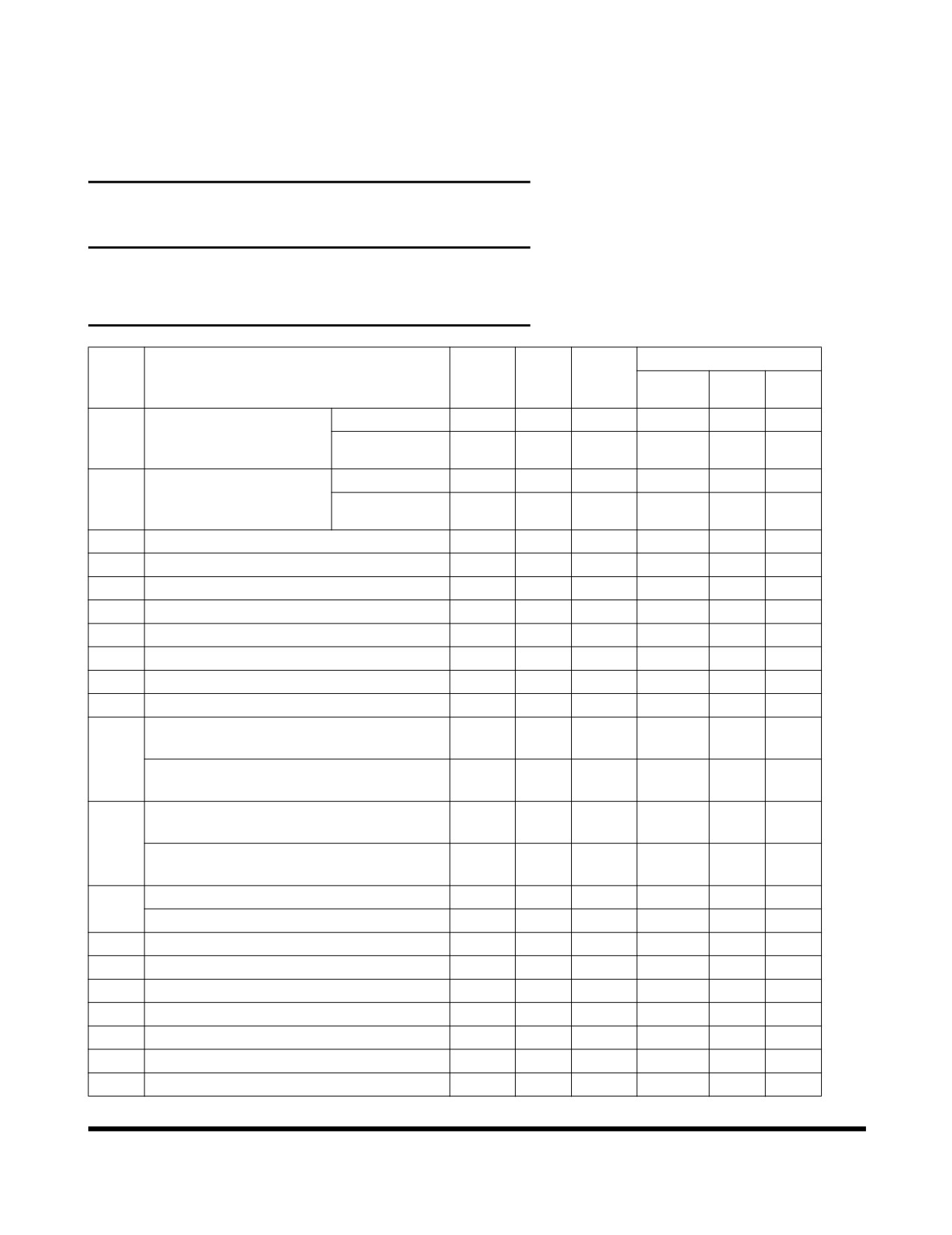
BOLT AND NUT INSPECTION
Inspect ALL fasteners after the first 50 hours of operation and
every 250 hours thereafter. If any are loose or are missing
tighten them or install new hardware. Always use a calibrated
torque wrench.
IMPORTANT
Always clean fasteners before tightening.
If counterweight is loose, contact a DOOSAN distributor or
sales agent.
BOLT
BOLT
TORQUE
NO.
POINT TO BE INSPECTED
DIA.
QTY.
HEAD
kg•m
Nm
ft lb
mm
SIZE
Joint bolt with engine
pump side
12
8
19
11.2
110
81
1
mounting bracket and
fan side
12
6
19
11.2
110
81
engine
Joint bolt and nut
pump side
20
2
30
46
451
333
2
between engine mount-
fan side
16
2
24
27
265
195
ing bracket and frame
3
Radiator mounting bolt
20
4
30
55
539
398
4
Tightening bolt for hydraulic oil tank
16
6
24
27
265
195
5
Tightening bolt for fuel tank
16
6
24
27
265
195
6
Tightening bolt for pump
20
4
17 (S)
49
480
354
7
Tightening bolt for control valve
16
4
24
27
265
195
8
Tightening bolt for swing reduction device
24
12
36
95
931
687
9
Tightening bolt for swing motor
12
16
10 (S)
11
108
80
10
Tightening bolt for battery
10
2
17
5
49
36
Joint bolt with cabin mounting rubber and
10
20
17
6.5
64
47
frame
11
Joint bolt with cabin mounting rubber and
16
5
24
21
206
152
cabin
Joint bolt with swing bearing and upper
24
35
36
95
931
687
frame
12
Joint bolt with swing bearing and bottom
24
36
36
95
931
687
frame
Tightening bolt for travel device
20
40
30
49
480
354
13
Tightening bolt for sprocket
20
48
30
49
480
354
14
Tightening bolt for upper roller
20
4
30
55
539
398
15
Tightening bolt for bottom roller
20
72
30
55
539
398
16
Tightening bolt for track guard
20
16
30
55
539
398
17
Bolt for track shoes
22
384
37
115
1127
832
18
Fixing bolt for front pin
16
10
24
27
265
195
19
Breaker Filter (Optional)
1
30
27
265
195
20
Grease valve for track adjuster
PF 1/2
2
27
14
137
101
Inspection, Maintenance and Adjustment
OP001005
4-59
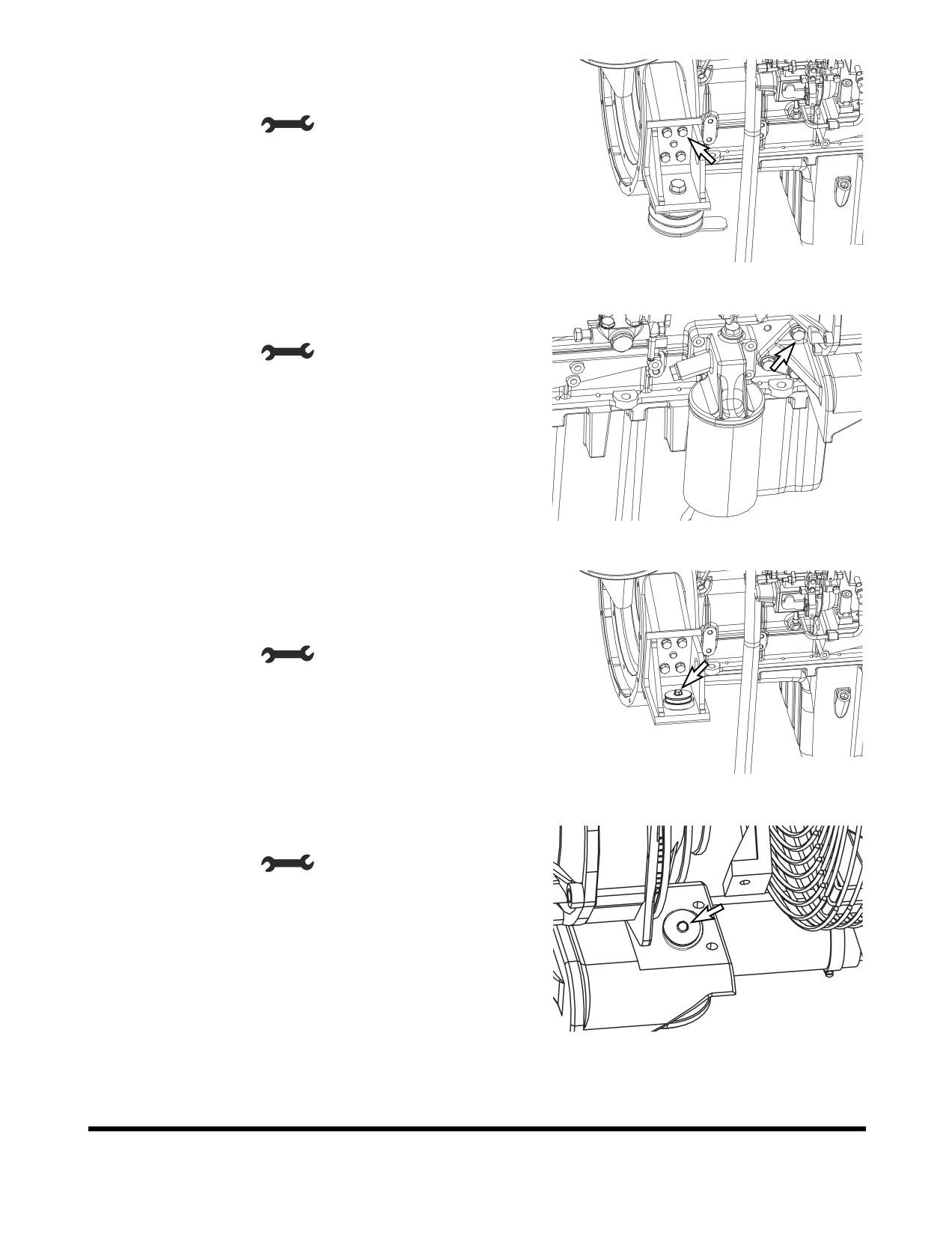
1.
Joint bolt with engine mounting bracket and engine
1) Pump side
•
Tool: 19 mm (
)
•
Torque:11.2 kg•m (110 Nm, 81 ft lb)
FG015486
Figure 100
2) Fan side
•
Tool: 19 mm (
)
•
Torque: 11.2 kg•m (110 Nm, 81 ft lb)
FG015487
Figure 101
2.
Joint bolt and nut between engine mounting bracket and
frame
1) Pump side
•
Tool: 24 mm (
)
•
Torque: 27 kg•m (265 Nm, 195 ft lb)
FG015488
Figure 102
2) Fan side
•
Tool: 24 mm (
)
•
Torque: 27 kg•m (265 Nm, 195 ft lb)
FG015489
Figure 103
Inspection, Maintenance and Adjustment
OP001005
4-60
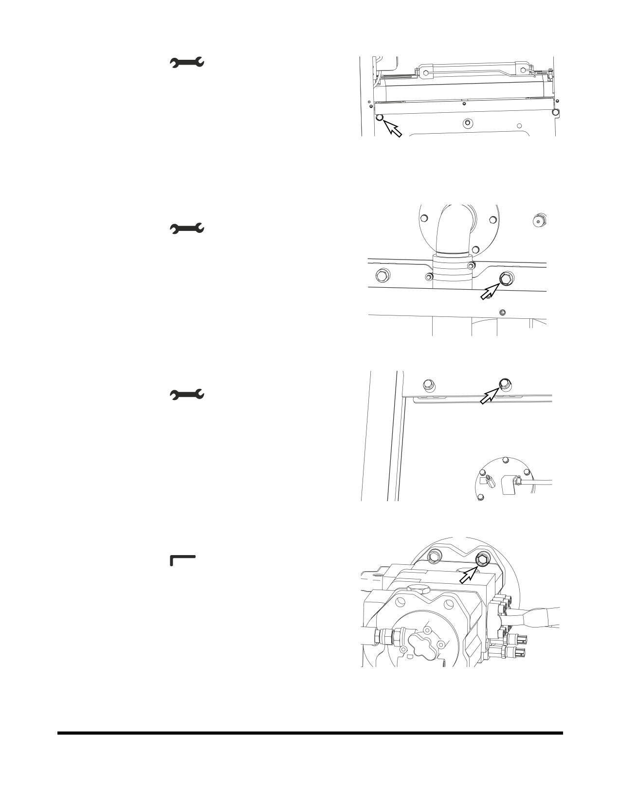
3.
Radiator mounting bolt
•
Tool: 30 mm (
)
•
Torque: 55 kg•m (539 Nm, 398 ft lb)
FG000446
Figure 104
4.
Tightening bolt for hydraulic oil tank
•
Tool: 24 mm (
)
•
Torque: 27 kg•m (265 Nm, 195 ft lb)
FG000447
Figure 105
5.
Tightening bolt for fuel tank
•
Tool: 24 mm (
)
•
Torque: 27 kg•m (265 Nm, 195 ft lb)
FG000448
Figure 106
6.
Tightening bolt for pump
•
Tool: 17 mm (
)
•
Torque: 49 kg•m (480 Nm, 354 ft lb)
FG000449
Figure 107
Inspection, Maintenance and Adjustment
OP001005
4-61
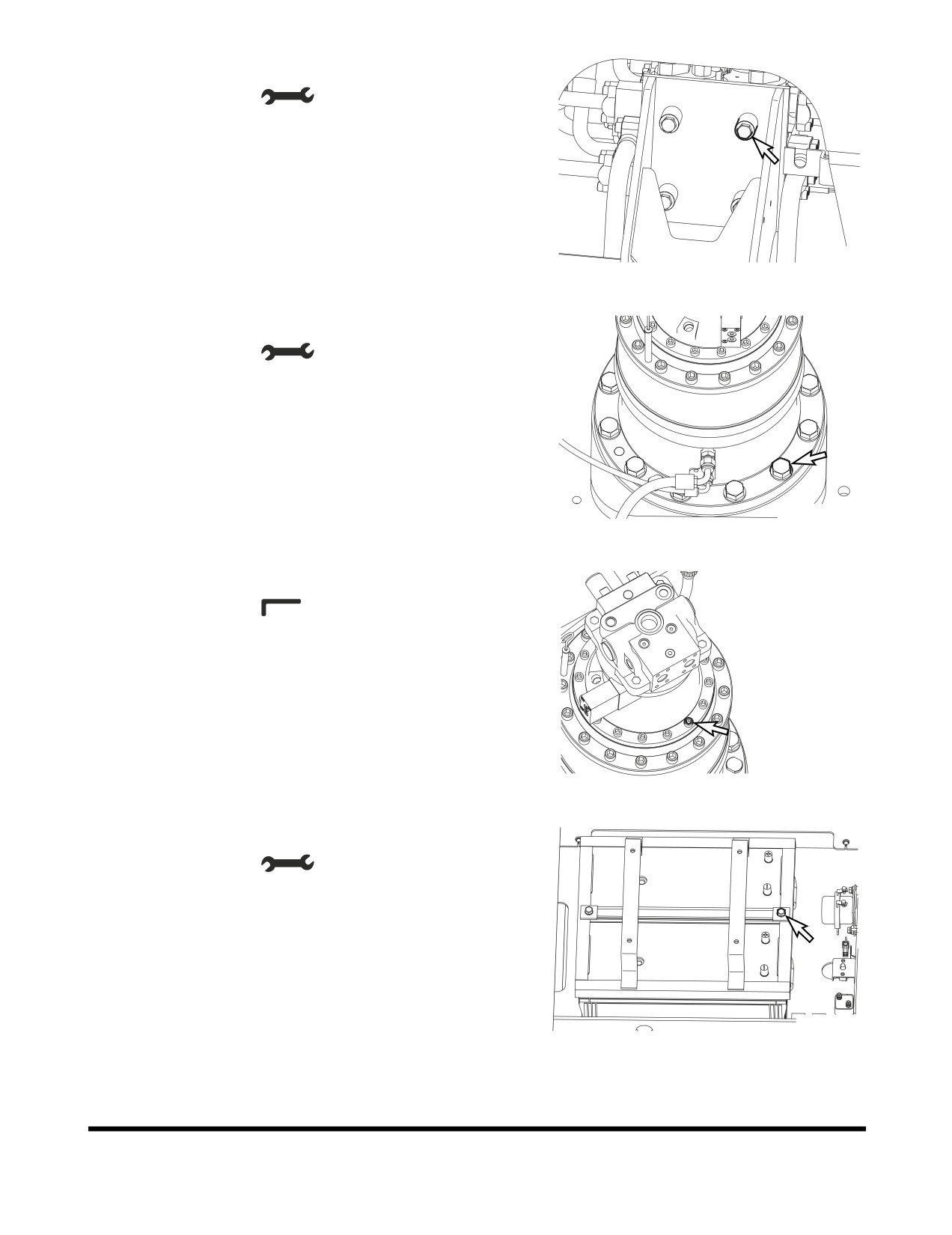
7.
Tightening bolt for control valve
•
Tool: 24 mm (
)
•
Torque: 27 kg•m (265 Nm, 195 ft lb)
FG000450
Figure 108
8.
Tightening bolt for swing reduction device
•
Tool: 36 mm (
)
•
Torque: 95 kg•m (931 Nm, 687 ft lb)
FG000451
Figure 109
9.
Tightening bolt for swing motor
•
Tool: 10 mm (
)
•
Torque: 11 kg•m (108 Nm, 80 ft lb)
FG000452
Figure 110
10. Tightening bolt for battery
•
Tool: 17 mm (
)
•
Torque: 5 kg•m (49 Nm, 36 ft lb)
FG000453
Figure 111
Inspection, Maintenance and Adjustment
OP001005
4-62
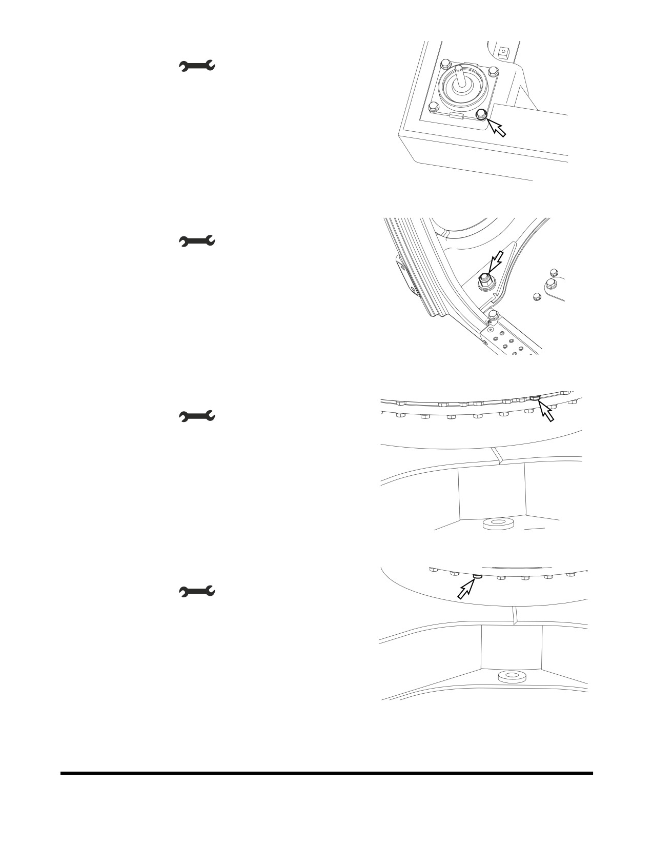
11. Joint bolt with cabin mounting rubber and frame
•
Tool: 17 mm (
)
•
Torque: 6.5 kg•m (64 Nm, 47 ft lb)
FG000454
Figure 112
Joint bolt with cabin mounting rubber and cabin
•
Tool: 24 mm (
)
•
Torque: 21 kg•m (206 Nm, 152 ft lb)
FG000455
Figure 113
12. Joint bolt with swing bearing and upper frame
•
Tool: 36 mm (
)
•
Torque: 95 kg•m (931 Nm, 687 ft lb)
FG000456
Figure 114
Joint bolt with swing bearing and bottom frame
•
Tool: 36 mm (
)
•
Torque: 95 kg•m (931 Nm, 687 ft lb)
FG000457
Figure 115
Inspection, Maintenance and Adjustment
OP001005
4-63
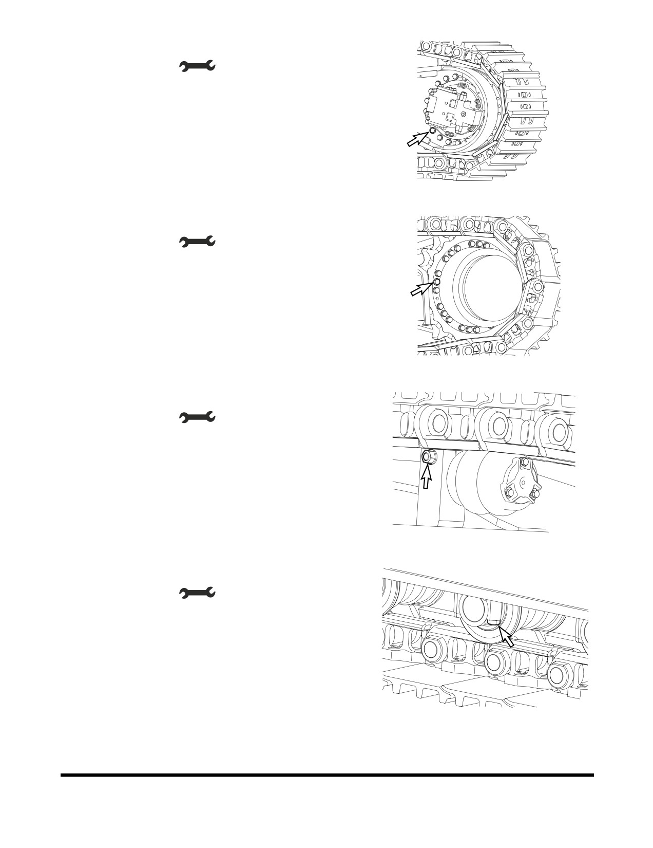
13. Tightening bolt for travel device
•
Tool: 30 mm (
)
•
Torque: 49 kg•m (480 Nm, 354 ft lb)
FG000458
Figure 116
Tightening bolt for sprocket
•
Tool: 30 mm (
)
•
Torque: 49 kg•m (480 Nm, 354 ft lb)
FG000459
Figure 117
14. Tightening bolt for upper roller
•
Tool: 30 mm (
)
•
Torque: 55 kg•m (539 Nm, 398 ft lb)
FG000460
Figure 118
15. Tightening bolt for bottom roller
•
Tool: 30 mm (
)
•
Torque: 55 kg•m (539 Nm, 398 ft lb)
FG000461
Figure 119
Inspection, Maintenance and Adjustment
OP001005
4-64
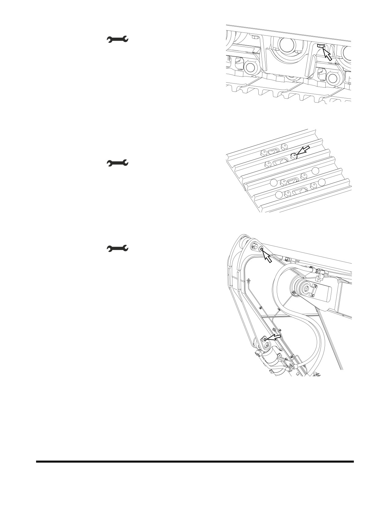
16. Tightening bolt for track guard
•
Tool: 30 mm (
)
•
Torque: 55 kg•m (539 Nm, 398 ft lb)
FG000462
Figure 120
17. Bolt for track shoes
Tighten the bolts in the order as shown in the Figure 121 (1
→ 4)
•
Tool: 37 mm (
)
4
•
Torque: 115 kg•m (127 Nm, 832 ft lb)
2
1
3
FG014337
Figure 121
18. Fixing bolt for front pin
•
Tool: 24 mm (
)
•
Torque: 27 kg•m (265 Nm, 195 ft lb)
FG000464
Figure 122
Inspection, Maintenance and Adjustment
OP001005
4-65
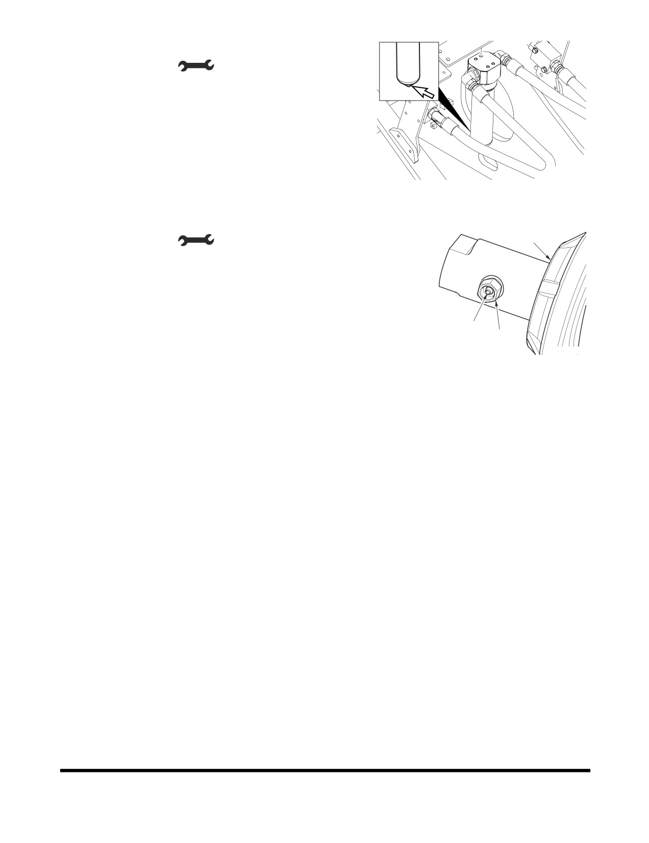
19. Fixing breaker filter (Optional)
•
Tool: 30 mm (
)
•
Torque: 27 kg•m (265 Nm, 195 ft lb)
FG000339
Figure 123
20. Grease valve for track adjuster
•
Tool: 27 mm (
)
2
•
Torque: 14 kg•m (137 Nm, 101 ft lb)
1
3
FG000163
Figure 124
Inspection, Maintenance and Adjustment
OP001005
4-66
BUCKET
Bucket Tooth Replacement
WARNING
Due to the possibility of flying metal objects, always wear
safety helmet, protective gloves and eye protection when
changing bucket teeth.
Curl the bucket upwards and place the round rear surface
of the bucket firmly on the ground. Shut the engine off and
lock out the hydraulic controls before working on the
bucket.
NOTE: These instructions are only for DOOSAN OEM
buckets. If you are using other manufacturers
buckets, refer to their specific instructions.
HAOC680L
Figure 125
1.
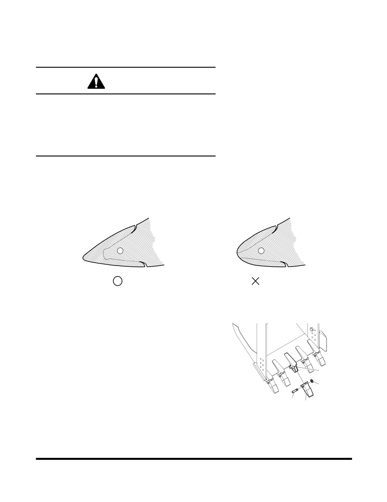
On a routine basis, inspect bucket teeth to make sure that
tooth wear or breakage has not developed. Do not allow
replaceable bucket teeth to wear down to a point that
bucket adapter is exposed. See Figure 125.
2.
To replace a tooth (1, Figure 126), use a hammer and
punch to drive locking pin (2) and lock washer (3) out of
tooth adapter (4).
4
3.
Once worn tooth has been removed, use a putty knife to
3
scrape adapter as clean as possible.
2
4.
Slide new tooth into position and insert lock washer.
1
FG000346
Figure 126
5.
Insert locking pin into tooth and with a hammer, drive pin in
until lock washer seats in locking groove.
Inspection, Maintenance and Adjustment
OP001005
4-67
Bucket O-ring Replacement
WARNING
Due to possibility of flying metal objects, always wear
safety helmet, protective gloves and eye protection when
changing pins.
1.
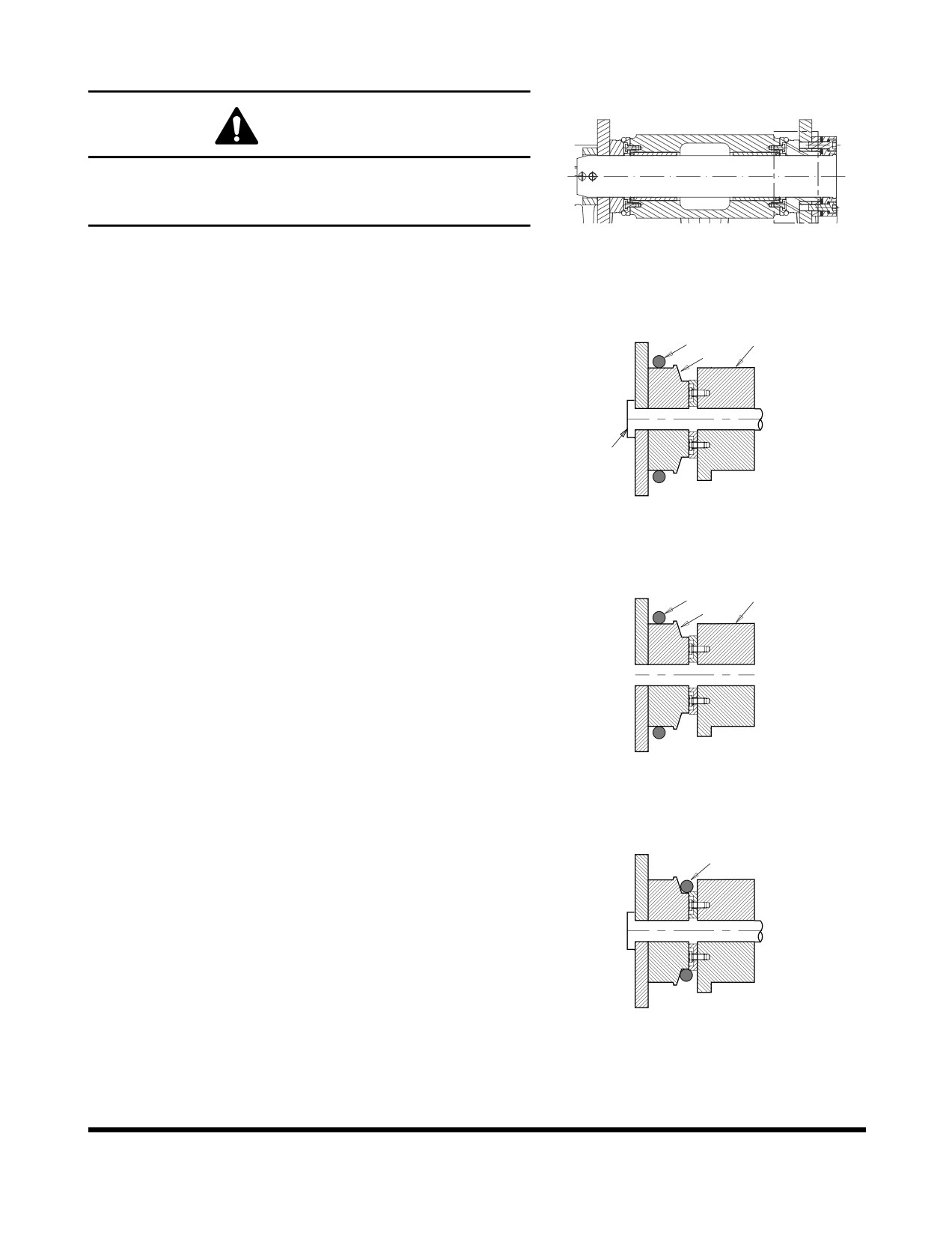
Inspect bucket O-rings on a routine basis. If worn or
FG000502
damaged, replacement is necessary.
Figure 127
2.
Roll old O-ring (1, Figure 128) onto boss (2) around bucket
pin (3). Remove bucket pin and move arm or bucket link
1
4
(4) out of way.
2
3
ARO1390L
Figure 128
3.
Remove old O-ring and temporarily install new O-ring (1,
Figure 129) onto bucket boss (2). Make sure that O-ring
1
4
groove on both bucket link
(4) and boss have been
2
cleaned.
4.
Realign arm or link with bucket pin hole and insert bucket
pin (3, Figure 128).
ARO1391L
Figure 129
5.
Roll new O-ring (1, Figure 130) into O-ring groove.
1
ARO1392L
Figure 130
Inspection, Maintenance and Adjustment
OP001005
4-68
BUCKET SHIMMING
PROCEDURES
New Bucket Installation
1.
If a new bucket is being installed on the excavator,
measure the inside dimension between the bucket ears
and the outside dimension across the arm mounting boss.
2.
Subtract the clearance on both sides from the difference of
the two and shim accordingly, before assembly.
WARNING
To check end play (side to side) clearance at bucket
attachment point, the bucket must be free to move but
at all other times lower it to the ground or use support
blocks to immobilize this assembly. Shut off engine
and tag and lock out controls to prevent movement
during this procedure.
Inspection, Maintenance and Adjustment
OP001005
4-69
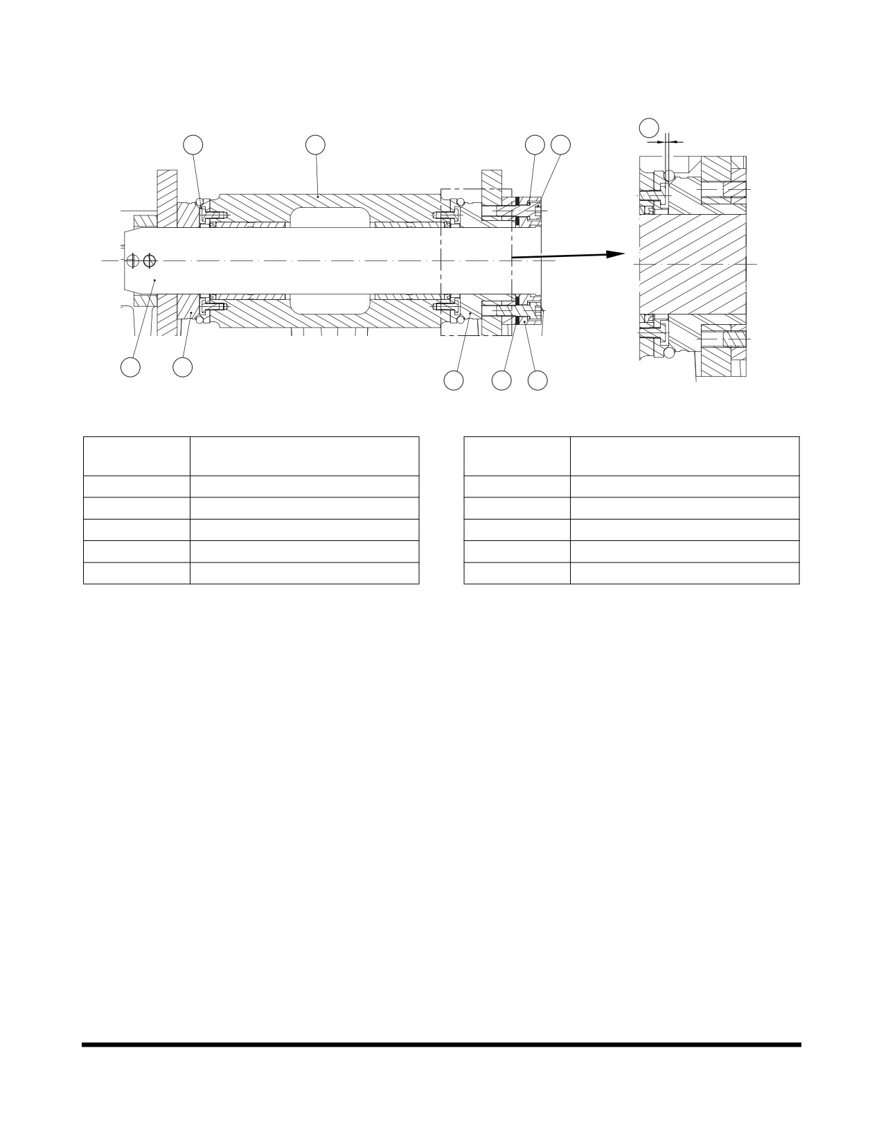
Shimming Procedures for Installed Bucket
3
1
2
8
7
5
10
9
4
6
FG000415
Figure 131
Reference
Reference
Description
Description
Number
Number
1
No Clearance
6
Plate
2
Arm
7
Bolt
3
Bucket Clearance
8
Hard Washer
4
Shim
9
Flange
5
Pin
10
Bucket Boss
1.
With bucket attached, curl bucket and arm outward and
lower boom so that bucket teeth are pointing away from
excavator, just a few inches off ground. This position
provides easy accessibility for dimensional measurements.
2.
Force bucket to one side and check for end play (side to
side) clearance under O-rings at attachment point. Total
clearance should be 1 mm (0.04 in) between side face of
boss and inside edge of ear bushing (3, Figure 131). Too
tight a fit (less than 1 mm (0.04 in)) can cause excessive
wear while too much clearance may produce excessive
noise and potentially hazardous slack control.
3.
Recheck end play by forcing bucket towards opposite side
and repeating clearance measurements.
4.
If an adjustment is required, detach stopper (6, Figure 131)
and bolts (7, Figure 131). Add or remove shims (4, Figure
131) as required. Use shims (4, Figure 131) on one side.
Tighten bolts with torque (27 kg•m) (7, Figure 131).
Inspection, Maintenance and Adjustment
OP001005
4-70
ELECTRICAL SYSTEM
NOTE: Never disassemble electrical or electronic parts.
Consult with a DOOSAN distributor or sales agency
before servicing.
Battery
WARNING
Battery electrolyte contains sulfuric acid and can quickly
burn the skin and eat holes in clothing. If you spill acid on
yourself, immediately flush the area with water.
Battery acid could cause blindness if splashed into the
eyes. If acid gets into the eyes, flush them immediately with
large quantities of water and see a doctor at once.
If you accidentally drink acid, drink a large quantity of water
or milk, beaten egg or vegetable oil. Call a doctor or poison
prevention center immediately.
When working with batteries, always wear safety glasses or
goggles.
Battery generates hydrogen gas, so there is danger of an
explosion. Do not bring lighted cigarettes near the battery,
or do anything that will cause sparks.
Before working with batteries, shut down engine and turn
the starter switch to the "O" (OFF) position.
Avoid short circuiting the battery terminals through
accidental contact with metallic objects, such as tool.
When removing or installing, check which is the positive (+)
terminal and negative (-) terminal.
When removing the battery, first disconnect the negative (-)
terminal. When installing the battery, first connect the
positive (+) terminal.
If the terminals are loose, there is danger that the defective
contact may generate sparks that will cause an explosion.
When installing the terminals, install them tightly.
Batteries in Cold Weather
In colder weather a greater drain is placed on the batteries when
they are used for the preheat cycle and when starting a cold
engine. Battery performance decreases as the temperature gets
lower.
In extremely cold weather, remove the batteries at night and
move them to a warm location. This will help to keep them at a
higher power level.
Inspection, Maintenance and Adjustment
OP001005
4-71
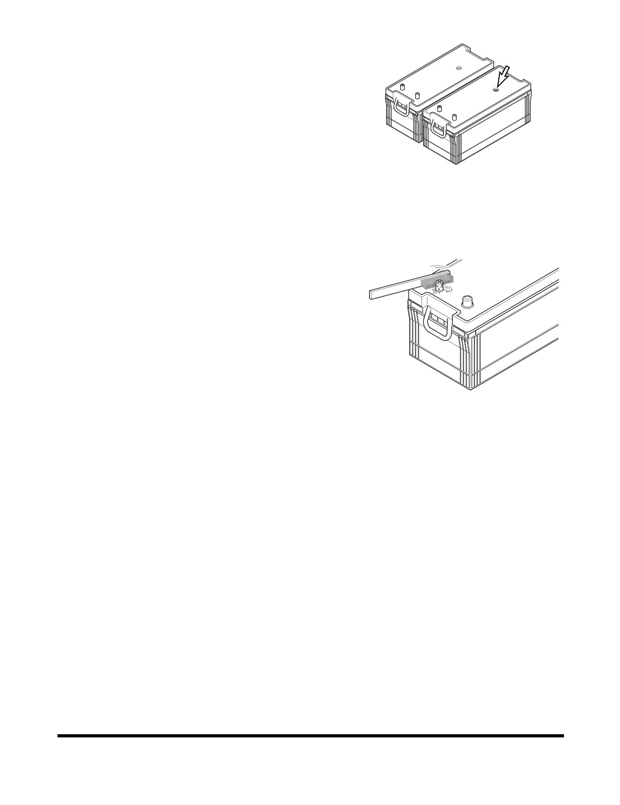
Inspection of Battery Electrolyte Level
This machine has two maintenance free batteries. They never
require the addition to water.
When the charge indicator becomes transparency, it means low
electrolyte state because of the leakage or charging system
error. Determine the cause of problem and replace the batteries
immediately.
Check Charging State
FG000347
Check charging state through the charging indicator.
Figure 132
•
GREEN: Sufficiently charged.
•
BLACK: Insufficient charged.
•
TRANSPARENT: Replace battery.
Check the Battery Terminals
Be certain that the battery is held securely in its compartment.
Clean the battery terminals and the battery cable connectors. A
solution of baking soda and water will neutralize acid on the
battery surface, terminals, and cable connectors. Petroleum jelly
or grease can be applied to the connectors to help prevent
corrosion.
Battery Replacement
When the charging indicator indicates transparency state,
HAOU790L
replace the battery. The batteries should always be replaced in
Figure 133
pairs.
Using an old battery with a new one will shorten the life span of
the new battery.
Inspection, Maintenance and Adjustment
OP001005
4-72
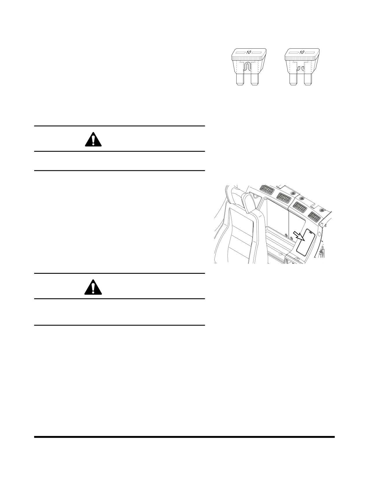
Fuses
1.
The fuses in the fuse box are used to protect the various
O
X
electrical circuits and their components from being
damaged. See Figure 134. The fuses used are standard
automotive type fuses.
2.
The section on “Fuse Identification” on page 4-74, lists the
circuits and the fuse amperage required for each circuit. If
a fuse blows, determine the cause and repair any faults or
failures.
HAOC670L
3.
Do not insert a higher amperage fuse into a lower
Figure 134
amperage slot. Serious damage to the electrical
components or fire can result.
CAUTION
Before replacing a fuse, be sure to turn starter switch to "O"
(OFF) position.
Fuse Boxes
There are two fuse boxes (Figure 135) on the left side of the
heater box. The fuses prevent electrical devices from
overloading or shorting.
A decal attached to the inside of the fuse box's cover indicates
the function and amperage of each fuse.
Spare fuses are mounted on the inside of fuse box's cover. (One
each of a 10A, 15A, 20A and 30A.)
Change a fuse if the element separates. If the element of a new
FG000110
fuse separates, check the circuit and repair the circuit.
Figure 135
CAUTION
Always replace fuses with the same type and capacity fuse
that was removed. Otherwise, electrical damage could
result.
Inspection, Maintenance and Adjustment
OP001005
4-73
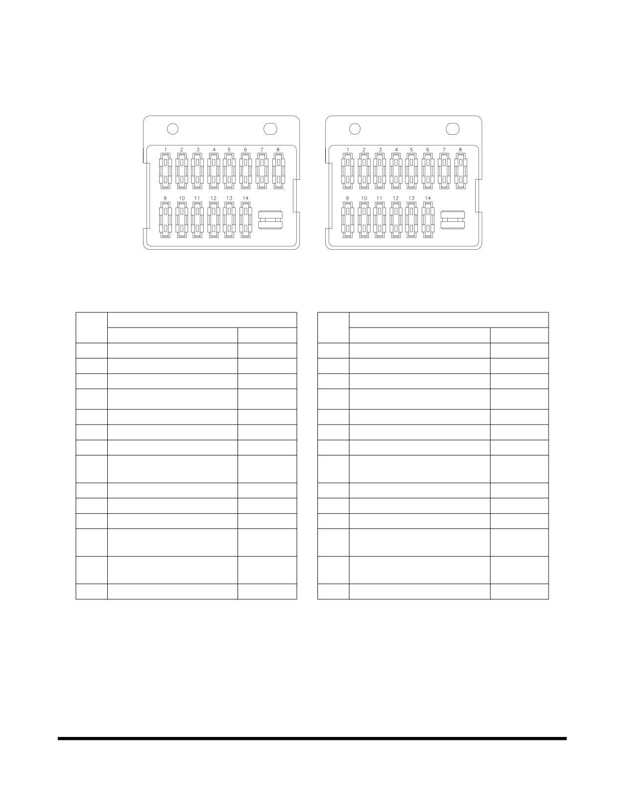
Fuse Identification
Fuse Box (1)
Fuse Box (2)
FG000542
Figure 136
Fuse Box One
Fuse Box Two
No.
No.
Name
Capacity
Name
Capacity
1
Warning Light (Optional)
10A
1
Horn
10A
2
2-pump (Optional)
10A
2
Quick Clamp (Optional)
10A
3
Cigar Lighter
10A
3
Travel Alarm (Optional)
10A
4
12V Power
10A
4
Auxiliary Mode
10A
5
Wiper, Washer
10A
5
Check Connector
10A
6
Lower Wiper (Optional)
10A
6
Pilot Cutoff
10A
7
Stereo
10A
7
Memory Backup
10A
Starter Switch, Hour
8
10A
8
Room Light
10A
Meter
9
Spare
30A
9
Cabin Light (Optional)
30A
10
Air Conditioner, Heater
20A
10
Work Light
20A
11
Shear, Breaker (Optional)
15A
11
Fuel Heater
20A
Instrument Panel, Pressure
12
Seat Heater (Optional)
15A
12
15A
Sensor
e-EPOS, Booster, Travel
13
15A
13
Headlight
15A
speed changer, Booster
14
ECU
15A
14
Fuel Pump (Optional), Wiper
15A
Inspection, Maintenance and Adjustment
OP001005
4-74
ENGINE COOLING SYSTEM
General
Keeping an engine's cooling system in peak operating condition,
can have many benefits to keeping a machine in good operating
condition. A properly functioning cooling system will; improve
fuel efficiency, reduce engine wear, and extend component life.
Always use distilled water in the radiator. Contaminants in tap
water neutralize the corrosion inhibitor components. If tap water
must be used, it should not exceed 300 ppm hardness, or
contain more than 100 ppm of either chloride or sulfate. Water
that has been treated with a water softener also contains salt
that will cause corrosion of components. Water from creeks and
stagnant pools usually contains dirt, minerals and/or organic
material that are deposited in the cooling system and impair
cooling efficiency. Distilled water is the best.
Engine overheating is often caused by bent or clogged radiator
fins. The spaces between the fins can be cleaned by use of air
or water under pressure. When straightening bent fins, use care
not to damage the tubes or break the bond between the fins and
the tubes.
WARNING
Pressure at air nozzle must not exceed 30 PSI (2.1 kg/cm2).
Always wear goggles when using compressed air.
Do not pour cold water into radiator when engine is very hot
and water level is below the top of the tubes. Such action
could result in damage to engine cylinder heads.
Heavy duty diesel engines require a balanced mixture of water
and antifreeze. Drain and replace the mixture every year or
2,000 hours of operation, which ever comes first. This will
eliminate buildup of harmful chemicals.
Antifreeze is essential in any climate. It broadens the operating
temperature range by lowering the coolant's freezing point and
by raising its boiling point. Do not use more than 50% antifreeze
in the mixture unless additional freeze protection is required.
Never use more than 68% antifreeze under any condition.
Inspection, Maintenance and Adjustment
OP001005
4-75
Types of Antifreeze
There are two main classifications of antifreeze available on the
market today.
1.
Ethylene Glycol - Doosan Genuine Antifreeze Solution
(for all seasons)
2.
Propylene Glycol - Doosan Genuine Antifreeze Solution
(for all seasons)
Ethylene glycol has been on the market for many years. Its
chemical properties do not provide the improved corrosion
resistance that propylene glycol does. Ethylene glycol is also
very hazardous to the environment, people and animals.
DOOSAN recommends that ethylene glycol be replaced with
propylene glycol.
The newer propylene glycol antifreeze comes in many different
colors. Some of the colors are pink, red, orange and yellow.
There are even some that come in a blue-green color. The
blue-green color makes it very difficult to tell the difference of
what type of antifreeze is in a cooling system. The colors are
only a dye added to the clear antifreeze. Do not rely on color.
Keep careful machine records of what brand and type of
antifreeze is used in the unit. If you are unsure of what type of
antifreeze is in the system, drain and flush the system.
CAUTION
Do not mix the ethylene glycol and propylene glycol
solutions. If these two chemicals are mixed, undesirable
chemicals may be formed, which damages the equipment.
Do not mix up the solutions from different manufacturers.
Otherwise, the performance may be deteriorated. It is
recommended to use the Doosan Genuine Product.
In the regions under extreme weather, the user should
determine the performance of the coolant suitable for the
weather condition and decide the replacement cycle.
Inspection, Maintenance and Adjustment
OP001005
4-76
Antifreeze Concentration Tables
Ethylene Glycol - Doosan Genuine Antifreeze Solution (for all seasons)
(2,000 Hour / Yearly)
Ambient Temperature
Cooling Water
Antifreeze
-10°C (14°F)
80%
20%
-15°C (5°F)
73%
27%
-20°C (-4°F)
67%
33%
-25°C (-13°F)
60%
40%
-30°C (-22°F)
56%
44%
-40°C (-40°F)
50%
50%
Propylene Glycol - Doosan Genuine Antifreeze Solution (for all seasons)
(2,000 Hour / Yearly)
Ambient Temperature
Cooling Water
Antifreeze
-10°C (14°F)
78%
22%
-15°C (5°F)
71%
29%
-20°C (-4°F)
65%
35%
-25°C (-13°F)
59%
41%
-30°C (-22°F)
55%
45%
-40°C (-40°F)
48%
52%
NOTE: Mixing ratio is for reference purpose only, and is not
an absolute standard.
NOTE: Replacement cycle of the Doosan Genuine Product is
2,000 hours or one year.
Inspection, Maintenance and Adjustment
OP001005
4-77
FUEL TRANSFER PUMP
(OPTIONAL)
WARNING
Do not dry operate fuel pump for more than fifteen seconds.
•
Cooling and lubrication of pump is achieved by
fuel passing through pump. If pump is dry
operated, heat generated by moving parts will
cause damage to pump rotors, vanes and seals.
To prevent unnecessary wear and/or damage to
pump do not dry operate fuel pump for more than
fifteen seconds.
Do not operate pump for more than fifteen minutes at a time.
•
Continuous usage of pump over recommended
time interval will cause overheating of motor and
will result in causing motor damage.
Do not use refueling pump for other types of fuel or fluids.
(Use only for diesel fuel.)
•
Do not use refueling pump for other types of fuel
which have a low flash point.
•
Do not use refueling pump for fuel contaminated
with water or high humidity. Moisture in pump
mechanism can cause rust and can create pump
failure.
Always operate pump using strainer installed on inlet hose.
This will prevent any foreign materials from being
introduced into pump. Always maintain pump and all of its
components in a clean condition.
•
If dirt or other foreign materials enter pump, it can
become lodged between the rotor and/or vanes
and generate heat which can cause pump
damage.
•
Do not remove strainer or use a strainer with
larger mesh to increase flow of fuel.
Be careful not to overfill or spill fuel.
Make sure direction of check valve is in line with flow
direction of fuel.
If any pump parts or components become lost, damaged or
inoperable, immediately replace it with a new ones.
IMPORTANT
If there are any sign of leakage while operating transfer
pump, inspect the following components to prevent any
fires or hazardous fuel spills.
•
Check all hoses leading to and from the transfer
pump.
•
Check all hose clamps.
•
Check transfer pump inlet port.
Inspection, Maintenance and Adjustment
OP001005
4-78
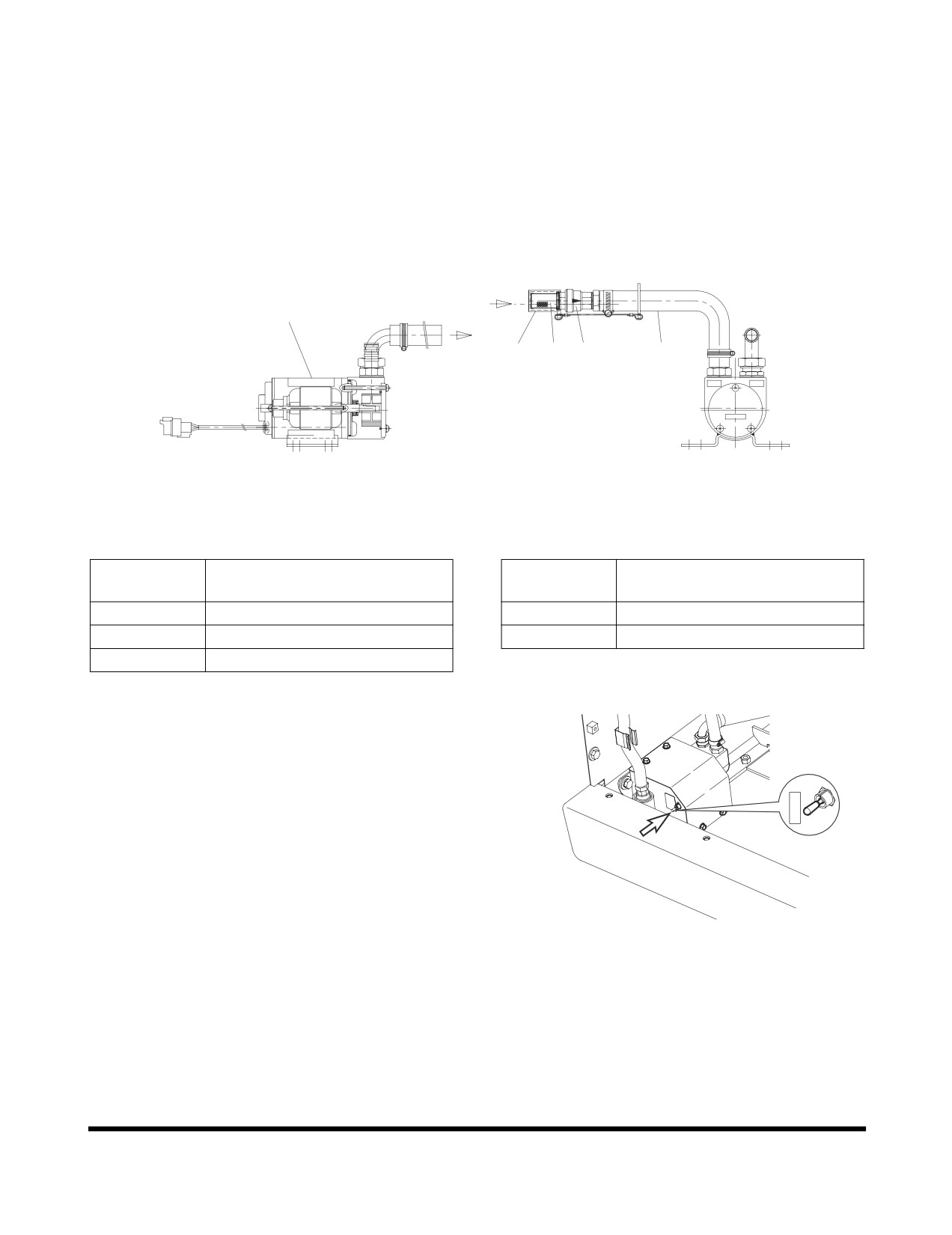
The transfer pump is used to transfer fuel from a refueling
source to the fuel tank. A check valve is installed in the inlet
hose to prevent fuel from flowing back from fuel tank to source.
A strainer is installed in inlet hose to prevent any foreign material
from being introduced into transfer pump or fuel tank.
A thermal limiter, built into the motor, will automatically shut off
power if motor is overheating to protect it from being damaged.
FUEL
1
4
3
2
5
FUEL TANK
IN
OUT
FG000161
Figure 137
Reference
Reference
Description
Description
Number
Number
1
Body
4
Strainer Cap
2
Check Valve
5
Inlet Hose
3
Strainer
1.
Remove strainer cap (4, Figure 137) from strainer (3) on
end of inlet hose (5).
NOTE: Keep strainer cap (4, Figure 137) in a safe
location to reseal strainer (3) after refueling is
complete.
I
O
2.
Insert inlet hose (5, Figure 137) into refueling tank.
3.
Turn fuel pump switch (Figure 138) inside of battery box on
front side to "I" (ON) position.
NOTE: Transfer pump rate of flow is approximately 35
liters/minute
(9.24 U.S. gpm). Use extra care
FG003379
not to overfill fuel tank so that fuel does not over
Figure 138
flow.
4.
Once fuel transfer is completed, immediately turn switch to
"O" (OFF) position to stop pump.
5.
Lift inlet hose (5, Figure 137) from fueling source and turn
switch to "I" (ON) position for two - three seconds to drain
remaining fuel from hose to fuel tank.
6.
Install strainer cap (4, Figure 137) on inlet strainer (3) and
return hose (5) to storage position.
Inspection, Maintenance and Adjustment
OP001005
4-79
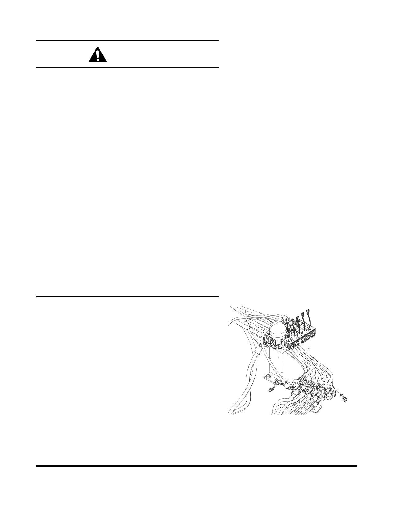
HANDLING OF ACCUMULATOR
WARNING
Even though the engine is stopped, the hydraulic
accumulators for the pilot system are still charged. Do not
disconnect any pilot system hoses until accumulator
pressure has been released from the circuit. To release
pressure, turn the starter switch to the "I" (ON) position and
operate all hydraulic control levers and forward/reverse
travel levers. Even though the engine is shutdown hydraulic
actuated components may move while releasing pilot
pressure. Keep all personnel away from excavator while
performing this operation.
•
Set safety lever on "LOCK" position after
stopping engine.
•
DO NOT mishandle accumulator(s). They are very
dangerous because they contain high-pressure
nitrogen gas.
•
DO NOT punch a hole or apply heat or fire to an
accumulator.
•
DO NOT weld on accumulator, or try attaching
anything to it.
•
When replacing an accumulator, contact a
DOOSAN distributor or sales agency so the gas
can be properly released.
•
Wear safety goggles and protective gloves when
working on an accumulator. Hydraulic oil under
pressure can penetrate the skin and cause
serious injuries.
Release pilot accumulator pressure using the following
procedure;
1.
Position the machine on firm, level ground. Lower the front
attachment to the ground and shut down engine.
2.
Set safety lever on "RELEASED" position.
3.
Turn starter switch to the "I" (ON) position.
4.
Fully stroke work and travel levers in all directions.
5.
Set safety lever on "LOCK" position.
6.
Turn key to "O" (OFF) position and remove from starter
switch.
7.
Remove accumulator by unscrewing it slowly.
FG013208
Figure 139
Inspection, Maintenance and Adjustment
OP001005
4-80
TRACK TENSION
WARNING
Safely measuring track tension requires two people. One
person must be in the operator's seat, running the controls
to keep one side frame in the air, while the other person
makes dimensional checks. Take all necessary precautions
to make sure the machine won't move or shift position
during service. Warm up the engine to prevent stalls, travel
the excavator to an area that provides level, uniform ground
support and/or use support blocks when necessary.
The track adjusting mechanism is under very
high-pressure. NEVER release pressure too suddenly. The
grease cylinder valve should never be backed off more than
one complete turn from the fully snugged down position.
Bleed off pressure slowly and keep your body away from
the valve at all times.
Track shoe link pins and bushings wear with normal usage,
reducing track tension. Periodic adjustment is necessary to
compensate for wear and it may also be required by working
conditions.
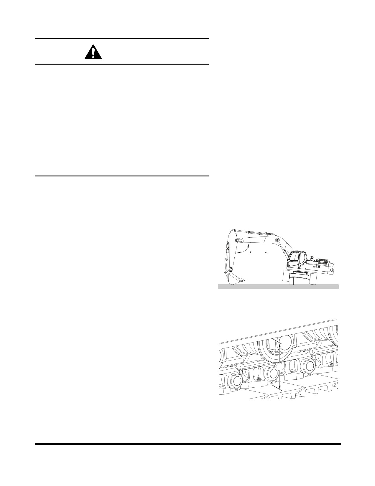
1.
Track tension is checked by jacking up one side of the
excavator. See Figure 140. Place blocking under frame
while taking measurement.
90 ~ 110
FG000345
Figure 140
2.
Measuring the distance
(A, Figure
141) between the
bottom of the side frame and the top of the lowest crawler
shoe. Recommended tension for operation over most
types of terrain is 320 - 340 mm (12.60 - 13.39 in)
NOTE: This measurement can be thrown off if there is
too much mud or dirt or other material in the
track assembly. Clean off the tracks before
A
checking clearance.
3.
Too little sag in the crawler track
(less than
320 mm
(12.60 in) clearance) can cause excessive component
FG000162
wear. The recommended adjustment can also be too tight
Figure 141
causing accelerated stress and wear if ground conditions
are wet, marshy or muddy, or if the ground is hard and full
of rocks or gravel.
Inspection, Maintenance and Adjustment
OP001005
4-81
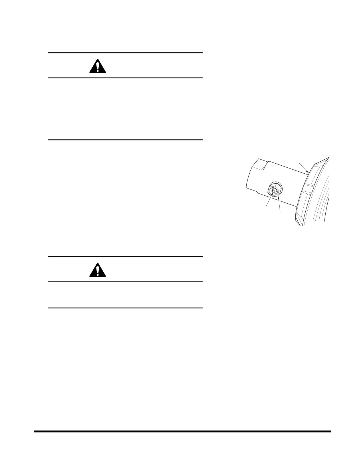
4.
The increased clearance recommended for muddy ground
conditions is between 340 - 370 mm (13.39 - 14.57 in). The
clearance should be approximately 370 mm (14.57 in) for
operation over gravel, rocky terrain, or over sand or snow.
WARNING
The track adjusting mechanism is under very
high-pressure. NEVER release pressure too suddenly.
The grease cylinder valve should never be backed off
more than 1 complete turn from the fully snugged
down position. Bleed off pressure slowly and keep
your body away from the valve at all times. If there is
problem in the fitting thread, the valve or fitting might
be ejected at high speed to cause fatal wound.
5.
Track tension adjustments are made through the grease
fitting
(1, Figure 142) in the middle of each side frame.
2
Adding grease increases the length of an adjustment
cylinder
(2). The longer the adjustment cylinder, the
greater the pressure on the tension spring pushing the
track idler wheel outward.
6.
If there is not enough slack or clearance in the tracks and
the adjustment is too tight, the idler wheel and adjusting
cylinder can be retracted by bleeding off grease through
1
hole in valve (3, Figure 142) by loosening valve slowly (3,
3
Figure 142).
FG000163
Figure 142
NOTE: After track tension is adjusted by loosening
valve, be sure to tighten valve (3, Figure 142)
with 14 kg•m (137 Nm, 101 ft lb).
WARNING
Do not loosen or remove the grease fitting (1, Figure
142) until the pressure is entirely bleed off by
loosening valve (3, Figure 142) slowly.
Inspection, Maintenance and Adjustment
OP001005
4-82
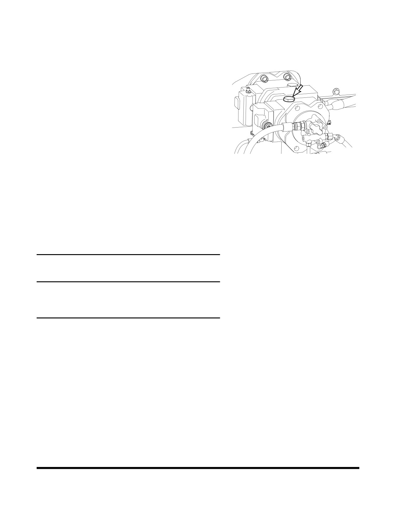
VENTING AND PRIMING
HYDRAULIC SYSTEM
Main System Pump
NOTE: If pump is run without sufficient oil in the main
hydraulic pump, damage can occur. Always vent
pump of air after draining hydraulic system.
1.
With the engine stopped, remove vent plug (Figure 143) to
see if any oil is present.
2.
If oil is not present, fill pump with oil through port (Figure
143).
3.
Install vent plug (Figure 143) first.
FG000158
Figure 143
4.
Start engine and run it for several minutes at low idle
engine speed. This will pressurize the hydraulic oil tank
and system.
5.
Slowly loosen vent plug (Figure 143) several turns, until
hydraulic oil flows out of plug. This shows that air has been
released.
6.
Tighten the plug (Figure 143).
Hydraulic Cylinders
IMPORTANT
If cylinders are operated in high idle after the hydraulic
system has been drained or the cylinder has been rebuilt,
damage to piston packing and seals may occur. Always
vent air from cylinders at low idle and at a slow speed.
1.
Run engine at low idle. Extend and retract each cylinder to
within 100 mm (4 in) of fully stroking it 4 - 5 times.
2.
Operate fully extend and retract each cylinder 3- 4 times.
3.
Repeat procedure until cylinders extend and retract
smoothly.
Inspection, Maintenance and Adjustment
OP001005
4-83
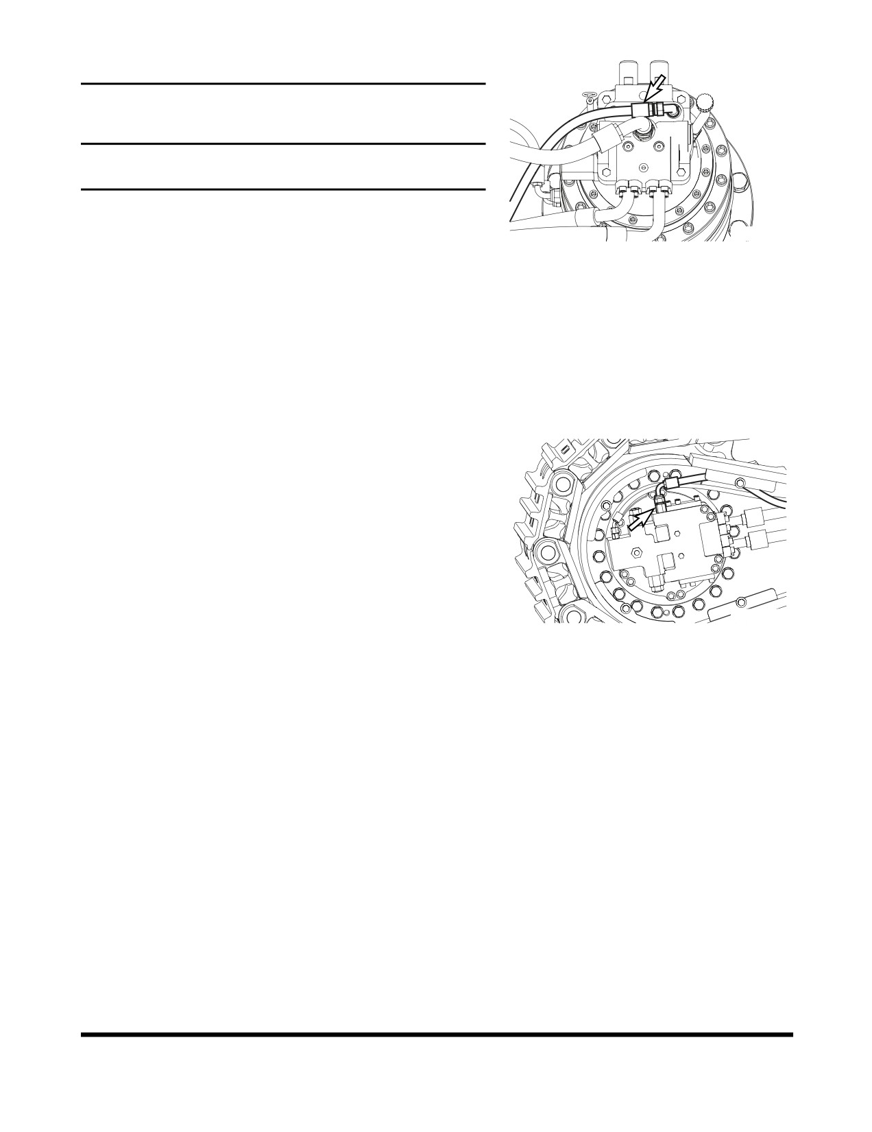
Swing Motor
IMPORTANT
If the air is not vented from the system, it will cause damage
to the swing motor and bearings.
NOTE: Perform this only when oil has been drained from
swing motor.
FG000159
1.
Shut down engine.
Figure 144
2.
Disconnect drain hose and fill swing motor case with
hydraulic oil.
3.
Connect the drain hose.
4.
Start engine and set throttle at "LOW IDLE" and swing
upper structure slowly two full revolutions to the left and
right.
Travel Motor
NOTE: Perform this only when oil is drained from travel
motor
1.
Shut down engine
2.
Disconnect drain hose (Figure 145) and fill motor case with
hydraulic oil.
3.
Connect drain hose.
4.
Start engine and set engine speed control dial to "LOW
FG000160
IDLE." Run the engine for one minute and slowly drive
Figure 145
excavator forwards and backwards.
General Venting
1.
After venting air from all components, shut the engine
down and check the hydraulic oil level. Fill hydraulic oil
tank to "H" mark on sight gauge.
2.
Start engine and operate all controls again, run engine for
five minutes to ensure all systems have been vent and
purged of air. Set engine speed to "LOW IDLE," and check
hydraulic oil level again. Add oil as necessary.
3.
Check for oil leaks and clean all fill and venting locations.
Inspection, Maintenance and Adjustment
OP001005
4-84
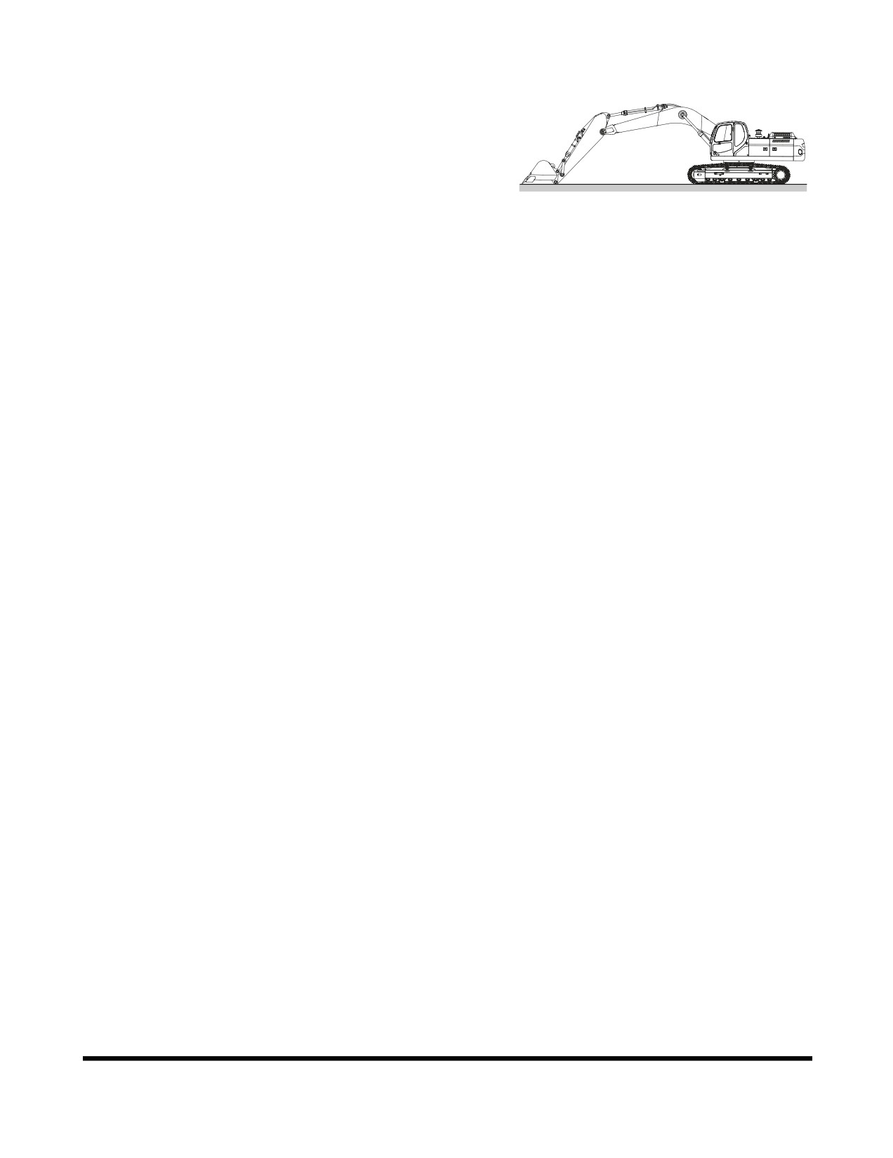
LONG TERM STORAGE
When a machine is taken out of service and stored for a time
exceeding 30 days, steps must be taken to protect the machine.
Leaving equipment outdoors exposed to the elements will
shorten its life.
An enclosure will protect the machine from rapid temperature
changes and lessen the amount of condensation that forms in
hydraulic components, engine, fuel tank, etc. If it is not possible
to put the machine in an enclosure, cover it with a tarpaulin.
FG014341
Check that the storage site is not subject to flooding or other
Figure 146
natural disasters.
After the machine has been positioned for storage and the
engine shut down, perform the following operations:
Before Storage
Keep the excavator in the position shown in Figure 92 to prevent
rust of the hydraulic piston rods.
•
Inspect for damaged, loose or missing parts.
•
Repaint necessary area to prevent oxidation.
•
Wash and clean all parts of machine.
•
Store the machine indoor, stable place. If stored
outside, cover with a waterproof tarpaulin.
•
Perform lubrication procedures on all grease points.
•
Apply a coating of light oil to the exposed plated
metal surfaces (such as hydraulic cylinder rods, etc.)
and to all the control linkage and control cylinders.
(Control valve spools, etc.)
•
Remove the battery from the excavator to be fully
charged and stored.
•
Inspect the coolant recovery tank and radiator to
make sure the antifreeze level in the system is
correct. Make sure that antifreeze concentration is
enough for the lowest temperature anticipated during
storage.
•
Seal all external openings (i.e. engine exhaust outlet,
crankcase and hydraulic breather, fuel vent line, etc.)
with tape wide enough to cover the opening,
regardless of size.
NOTE: When sealing with tape, be sure to extend
tape approximately one inch
(25 mm)
beyond opening to insure a good seal.
Inspection, Maintenance and Adjustment
OP001005
4-85
During Storage
•
Once a month, start the engine and follow the
"Hydraulic Oil Warm-up" procedures listed in this
manual.
NOTE: Remove all seals from the machine (i.e.
crankcase and hydraulic breathers, engine
air intake, fuel tank vent lines, etc.).
Operate hydraulic functions for traveling, swing and
digging two or three times for lubrication after
"Hydraulic Oil Warm-up." Coat all the moving parts
and surfaces of the components with a new oil film
after operating. At the same time, charge the battery.
Rotate track to prevent track seizing. "
•
Every 90 days, use a hydrometer to measure the
protection of the coolant. Refer to the antifreeze/
coolant protection chart to determine protection of the
cooling system. Add coolant as required.
After Storage
•
When operating the work equipment, remove all
grease from the hydraulic cylinder rods.
•
Add grease and oil at all lubrication points.
•
Adjust fan and alternator belt tension.
•
Connect the charged battery.
•
Check condition of all hoses and connections.
•
Check the levels of engine oil, fuel, coolant and
hydraulic circuit oil. If there is water in the oil, change
all the oil.
•
Change all filter elements.
•
When starting the engine after long-term storage,
follow the "Hydraulic Oil Warm-up" procedures listed
in this manual.
Inspection, Maintenance and Adjustment
OP001005
4-86
MAINTENANCE IN SPECIAL
CONDITIONS
NOTE: See
“Operation Under Unusual Conditions” on
page 3-42 for other recommendations.
Conditions
Maintenance Required
Operating in mud, water or rain.
Perform a walk around inspection to check for any loose
fittings, obvious damage to the machine or any fluid leakage.
After completing operations, clean mud, rocks or debris from
the machine. Inspect for damage, cracked welds or loosened
parts.
Perform all daily lubrication and service.
If the operations were in salt water or other corrosive materials,
make sure to flush the affected equipment with fresh water.
Operating in an extremely dusty or hot
Clean the air intake filters on a more frequent basis.
environment.
Clean the radiator and oil cooler fins to remove embedded dirt
and dust.
Clean the fuel system intake strainer and fuel filter more
frequently.
Inspect and clean as required the starter and alternator.
Operating in rocky terrain.
Check the undercarriage and track assemblies for damage or
excessive wear.
Inspect for loose or damaged fittings or bolts.
Relax track tension.
On a more frequent basis, inspect the front end attachments for
damage or excessive wear.
Install a top guard and front guard as required for protection
against falling rock.
Operating in extreme cold.
Use the proper fuel for the temperature conditions.
Using a hydrometer, check the antifreeze to make sure that it is
providing the proper cold weather freeze protection.
Verify the condition of the batteries. In extremely cold weather
remove the batteries at night and store them in a warmer area.
Remove mud buildup as soon as possible to prevent it from
freezing to the undercarriage and causing damage.
Inspection, Maintenance and Adjustment
OP001005
4-87
Inspection, Maintenance and Adjustment
OP001005
4-88
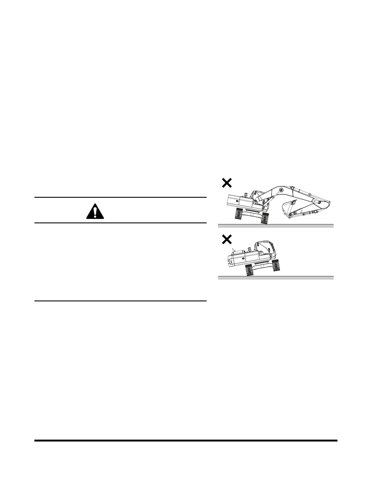
OP001006
5Transportation
Obey all local, state or federal regulations for the transportation
of the excavator. If unsure of regulations check with local
authorities.
Check the intended route for road width, overhead clearances,
weight restrictions, and traffic control regulations. Special
approval or permits may be required.
LOADING AND UNLOADING
Warning for Counterweight and Front
Attachment Removal
DANGER
DOOSAN warns any user, that the removal of the
counterweight from the machine, front attachment or any
other part, may affect the stability of the machine. This
could cause unexpected movement, resulting in death or
serious injuries. DOOSAN is not liable for any misuse.
Never remove the counterweight or front attachment unless
the upper structure is in-line with the lower structure.
FG000371
Never rotate the upper structure once the counterweight or
Figure 1
front attachment has been removed.
Transportation
OP001006
5-1
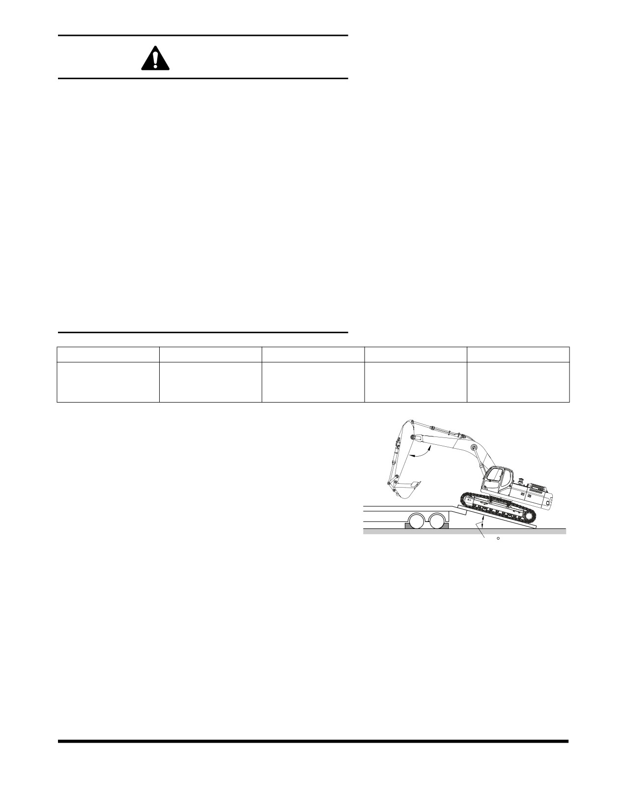
WARNING
When transporting the machine, know the width, height,
length and weight.
Loading or unloading the machine can be a dangerous
operation. Make sure to run the engine at the lowest speed
setting, and travel at the slowest speed possible.
Make sure that the ramp being used can handle the weight
of the machine. If required, add blocking under the ramp for
additional support.
Make sure that the ramp surface is free of grease or mud
that could cause the machine to slip or slide.
Make sure that the trailer is parked on firm, level ground
before attempting to load/unload the excavator.
If it is required to turn the machine while it is on the trailer,
make sure to do this at the slowest engine and travel
speeds possible.
Make sure to secure the excavator onto the trailer as
required by local transportation laws.
Total Height
Total Width
Total Length
Weight
Remarks
6.25 m Boom
3,345 mm
3,200 mm
10,620 mm
29.3 metric tons
3.1 m Arm
(11' 0")
(10' 6")
(418.11 in)
(32.23 tons)
600 G Shoe
1.
Make sure that the trailer is parked on firm, level ground.
See Figure 2.
2.
Make sure that the ramps that are being used are designed
to handle the weight of the excavator. If required, add
90 ~ 110
blocking under the ramp to provide additional support.
3.
The ramp angle should be less than or not exceeding a 15°
angle. Ramps steeper than this may cause a problem
when loading or unloading.
15
FG000325
Figure 2
Transportation
OP001006
5-2
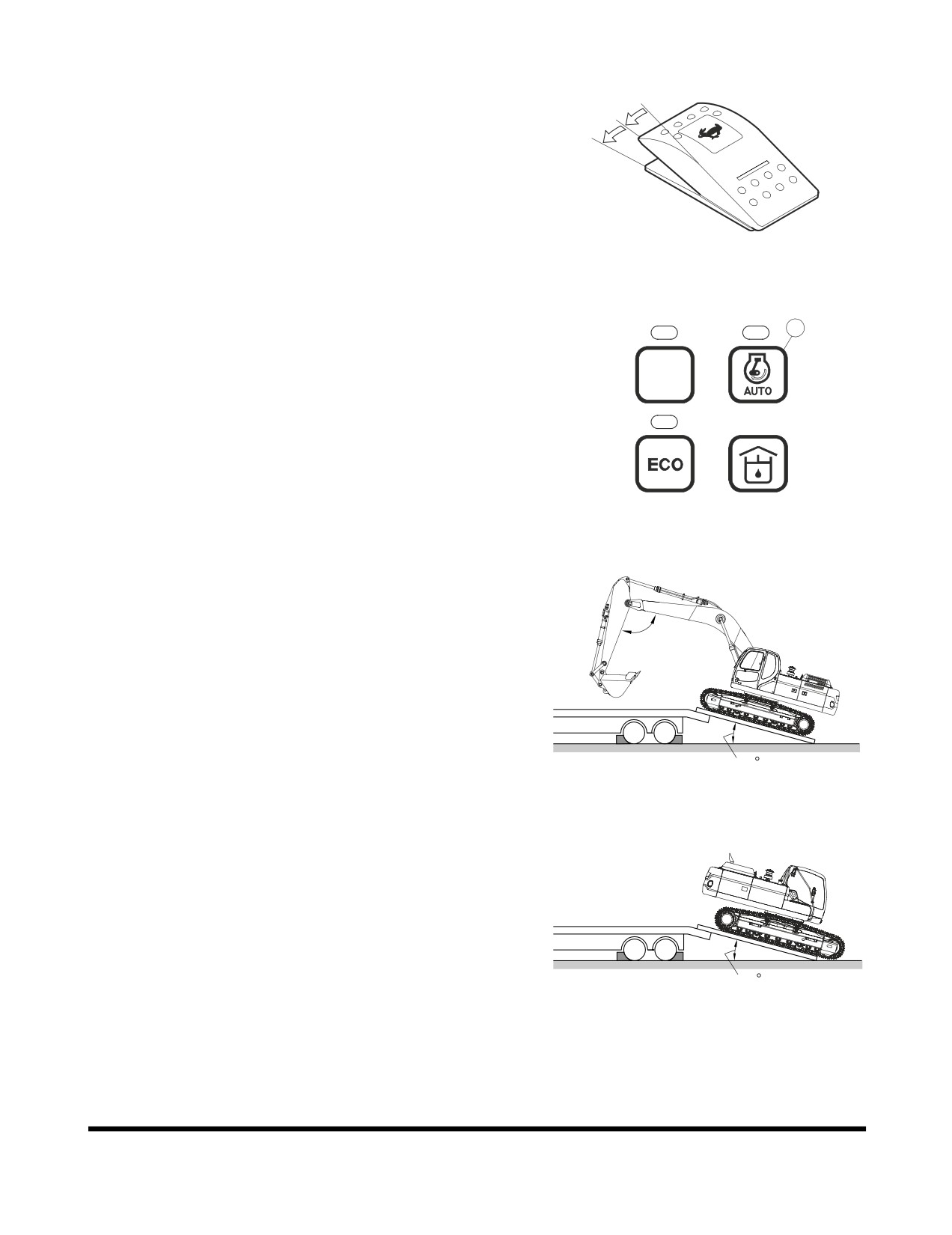
4.
Set the travel speed selector switch to "O" (OFF) position.
See Figure 3.
O
I
II
FG000023
Figure 3
5.
Turn "OFF" auto idle selector button (1, Figure 4). The
1
indicator light will be disappeared.
6.
Set engine speed to "LOW IDLE."
POWER
1
2
5
6
FG015474
Figure 4
7.
If the machine is equipped with work equipment, set the
work equipment at the front, and travel forward to load it.
90 ~ 110
15
FG000325
Figure 5
8.
The unit does not require disassembly for normal
over-the-road transportation. If the boom and arm need to
be removed, the counterweight will place more weight on
the rear of the machine. Make sure to back the excavator
onto the trailer so that the counterweight end of the
excavator is positioned on the ramp first. See Figure 6.
15
FG000326
Figure 6
Transportation
OP001006
5-3
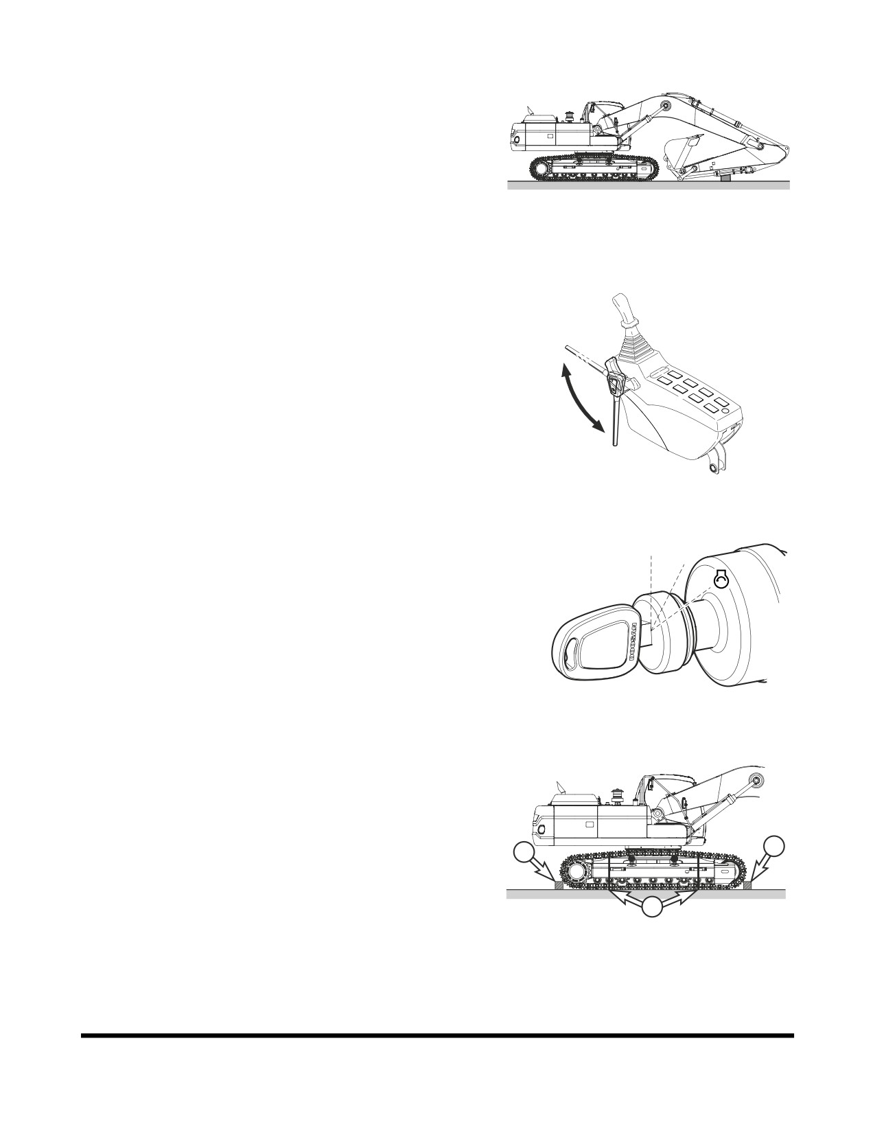
9.
Extend bucket and arm cylinders to maximum length and
then lower the boom slowly.
FG000327
Figure 7
10. Set safety lever on "LOCK" position.
Unlock
lock
FG001091
Figure 8
11. Shut down engine by turning key to "O" (OFF) position
(Figure 9).
O
I
12. Remove key from starter switch.
FG000175
Figure 9
13. Make sure to secure the excavator onto the trailer before
transporting. Place blocking (1, Figure 10) in front of and
behind each track. Tie front and rear (2, Figure 12) and tie
down point (3, Figure 12) on the lower frame with wire
cable as required by local transportation laws.
1
14. Refer to the Dimensions for Transportation table and
1
drawing for overall machine height and width
measurements. Make sure to position the excavator as
shown. If not transported in this position, the height
2
measurements may be different.
FG000334
Figure 10
Transportation
OP001006
5-4
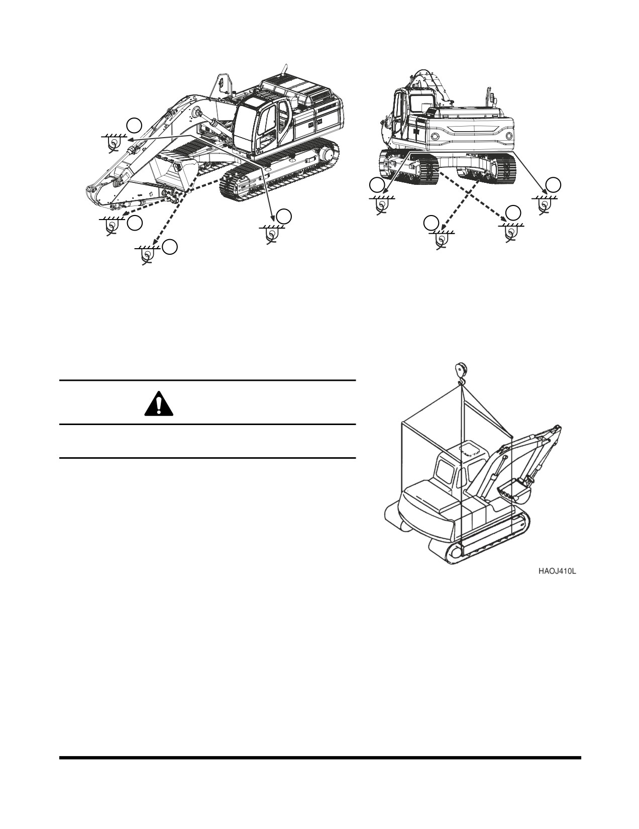
2
2
2
3
2
3
3
3
FG014870
Figure 11
LIFTING WITH SLING
WARNING
Improper lifting can allow load to shift and cause injury or
damage.
1.
Refer to “Specification” on page 7-1 of this manual for
information on weight and dimensions.
2.
Use properly rated cables and slings for lifting.
3.
Position machine for a level lift.
4.
Lifting cables should have a long enough length to prevent
contact with the machine. Spreader bars may be required.
NOTE: If spreader bars are used, be sure that cables
are properly secured to them and that the angle
Figure 12
of the cables is factored into the lift strength.
Transportation
OP001006
5-5
Transportation
OP001006
5-6
OP001007
6Troubleshooting
Anytime that a malfunction occurs, take immediate corrective
action. Check for and investigate the cause of the malfunction. A
schedule maintenance program can prevent malfunctions from
occurring by doing preventative maintenance. A systematic
approach should be taken to troubleshooting, since several
overlapping malfunctions may give the appearance of a problem
that does not exist. If cause for the malfunction cannot be
determined, contact your DOOSAN distributor. Never perform
an adjustment of or disassembly of, hydraulic components,
electrical and electronic components, without first consulting a
DOOSAN distributor.
ELECTRICAL SYSTEM
Problem
Cause
Remedy
Battery will not hold a
Low battery power.
Clean and retighten.
charge.
Alternator belt loose or bad.
Tighten or replace belt.
Loose or corroded terminals.
Tighten or replace as required.
Alternator faulty.
Repair or replace as required.
Low battery power.
Internal battery short.
Replace battery.
Short circuit in wiring.
Repair as required.
Engine speed is not
Speed control dial failed.
Replace control dial.
controllable.
Throttle controller failed.
Replace controller.
Speed control motor failed.
Repair or replace as required.
Blown fuse.
Replace fuse.
Wiring harness damaged.
Repair or replace as required.
Connector failed.
Repair or replace as required.
Work mode (Power mode or
Blown fuse.
Replace fuse.
Economy mode) selector
Work mode selector switch failed.
Replace switch.
does not work.
Connector failed.
Replace connector.
Wiring harness damaged.
Repair or replace as required.
e-EPOS controller failed.
Repair or replace as required.
Troubleshooting
OP001007
6-1
Problem
Cause
Remedy
Working mode selector does
Blown fuse.
Replace fuse.
not work.
Working mode selector switch.
Replace switch failed.
Connector failed.
Replace connector.
Wiring harness damaged.
Repair or replace as required.
e-EPOS controller failed.
Repair or replace as required.
ENGINE
Problem
Cause
Remedy
Starter does not operate.
Low battery power.
Charge battery.
Poor terminal contact.
Clean and tighten connections.
Starter switch failed.
Replace switch.
Starter relay failed.
Replace relay.
Starter controller failed.
Replace controller.
Wiring harness faulty.
Replace harness.
Battery relay failed.
Replace relay.
Blown fuse.
Replace fuse.
Starter engages, engine
Fuel gelled in cold weather.
Replace fuel.
does not start.
Fuel filters plugged.
Replace filters.
Water or dirt in fuel system.
Clean system and add new fuel.
Air in fuel system.
Purge air from system.
Engine stop control failed.
Contact your DOOSAN dealer.
Engine stop relay failed.
Replace relay.
Blown fuse.
Replace fuse.
Engine starts, runs only at
Engine oil viscosity incorrect.
Change oil.
low speed or shuts down.
Clogged or dirty fuel injectors.
Clean injectors.
Fuel filters plugged.
Replace filters.
Engine stop motor cable out
of
Readjust
adjustment.
Engine speed control cable out of
Readjust
adjustment.
Troubleshooting
OP001007
6-2
Problem
Cause
Remedy
Engine knocks, runs
Low engine oil.
Refill.
unevenly or surges.
Plugged air intake system.
Clean system and replace filter.
Injection pump out of adjustment.
Contact your DOOSAN dealer.
Plugged fuel filter.
Replace fuel filter.
Water or dirt in fuel system.
Clean system and add new fuel.
Clogged or dirty fuel injectors.
Clean injectors.
Engine has poor power.
Plugged air intake system.
Clean system and replace filter.
Clogged or dirty fuel injectors.
Clean injectors.
Fuel filters plugged.
Replace filters.
Engine speed control cable out of
Readjust.
adjustment.
Injection pump out of adjustment.
Contact your DOOSAN dealer.
Valve backlash faulty.
Adjust backlash.
Engine runs hot.
Low coolant level.
Add coolant.
Thermostat faulty.
Replace thermostat.
Radiator cap faulty.
Replace radiator cap.
Radiator core plugged.
Clean radiator.
Oil cooler core plugged.
Clean oil cooler.
Fan belt loose or damaged.
Tighten or replace as required.
Temperature sensor faulty.
Replace sensor.
HYDRAULIC SYSTEM
Problem
Cause
Remedy
None of the controls
Hydraulic pump failed.
Contact your DOOSAN dealer.
function (loud noise from
Low hydraulic oil level.
Add hydraulic oil as required.
pumps).
Suction line plugged or damaged.
Clean or replace as required.
None of the controls
Pilot pump failure.
Contact your DOOSAN dealer.
function (no noise from
Cut off solenoid valve failed.
Replace solenoid.
pumps).
Pilot cutoff switch is ON.
Adjust pilot cutoff switch clearance.
Troubleshooting
OP001007
6-3
Problem
Cause
Remedy
All actuators have low
Low hydraulic oil level.
Add hydraulic oil as required.
power.
Suction filter clogged.
Clean filter.
Hydraulic pumps faulty.
Contact your DOOSAN dealer.
Main relief pressure too low.
Contact your DOOSAN dealer.
Hydraulic pumps excavating.
Bleed air from hydraulic pumps.
Only one or two actions
Overload relief pressure too low.
Reset pressure.
have little or no power.
Makeup check valve leaking.
Clean or replace as required.
Control valve spool faulty.
Replace valve spool.
Dirt in valve spool.
Clean or replace as required.
Actuator failed.
Repair or replace as required.
Cylinder seal failed.
Repair or replace as required.
Cylinder rod damaged.
Repair or replace as required.
Remote control valve failed.
Replace control valve.
Wrong pilot line connection.
Reconnect pilot lines.
Oil temperature too high.
Oil cooler faulty.
Contact your DOOSAN dealer.
Fan belt loose.
Tighten fan belting as required.
SWING SYSTEM
Problem
Cause
Remedy
No swinging motion.
Swing brake valve faulty.
Replace brake valve.
Hydraulic timer faulty.
Replace timer.
Low brake release pressure.
Adjust pressures.
Swing motor failed.
Replace swing motor.
Remote control valve failed.
Replace control valve.
Wrong pilot line connection.
Reconnect pilot lines.
Swing motion jerky.
Swing gear worn.
Replace swing gear.
Swing bearing damaged.
Replace bearing.
Improper lubrication.
Add grease.
Troubleshooting
OP001007
6-4
TRAVEL SYSTEM
Problem
Cause
Remedy
Travel motion does not
Center joint leaking.
Repair or replace as required.
function.
Parking brake will not release.
Repair parking brake.
Travel motor failed.
Repair or replace as required.
Remote control valve failed.
Repair or replace as required.
Wrong pilot line connection.
Reconnect pilot lines.
Travel speed is too low.
Track tension too high or too low.
Adjust tension.
Damaged rollers or idlers.
Repair or replace as required.
Track frame damaged.
Repair as required.
Parking brake will not release.
Repair parking brake.
Troubleshooting
OP001007
6-5
Troubleshooting
OP001007
6-6
OP001008
7Specification
STANDARD SPECIFICATION
SPECIFICATION
COMPONENT
METRIC
ENGLISH
Bucket
CECE
1.1 m3
1.44 yd3
capacity
PCSA
1.27 m3
1.66 yd3
Equipment weight
29.6 metric tons
32.6 tons
Engine
Model
DE08TIS
Type
Water cooled - 6 cylinders
Rated output
200 ps @1,900 rpm
197 hp @1,900 rpm
Maximum torque
86 kg•m @ 1,300 rpm
622 ft lb @ 1,300 rpm
Fuel tank capacity
500 liters
132 U.S. gal.
Hydraulic
Type
Axial piston
pump
Discharging pressure
350 kg/cm2
5,000 psi
Maximum discharge quantity
2 x 247 liters/min
2 x 65.2 U.S. gpm
Hydraulic oil
Tank Level
160 liters
42 U.S. gal.
capacity
System
280 liters
74 U.S. gal.
Performance
Digging
Bucket
18.0 metric tons
19.8 tons
capability
Arm
13.4 metric tons
14.8 tons
Swing speed
9.9 rpm
Travel speed
High speed
5.1 km/h
3.17 MPH
Low speed
3.0 km/h
1.86 MPH
Traction force
High speed
13.7 metric tons
15.1 tons
Low speed
25.2 metric tons
27.7 tons
Gradeability
35° (70% slope)
Ground pressure
0.56 kg/cm2
7.97 psi
Ground clearance
500 mm
19.7 in
Track shoe width
600 mm
23.6 in
Upper roller qty.
2 per side
Bottom roller qty.
9 per side
Specification
OP001008
7-1
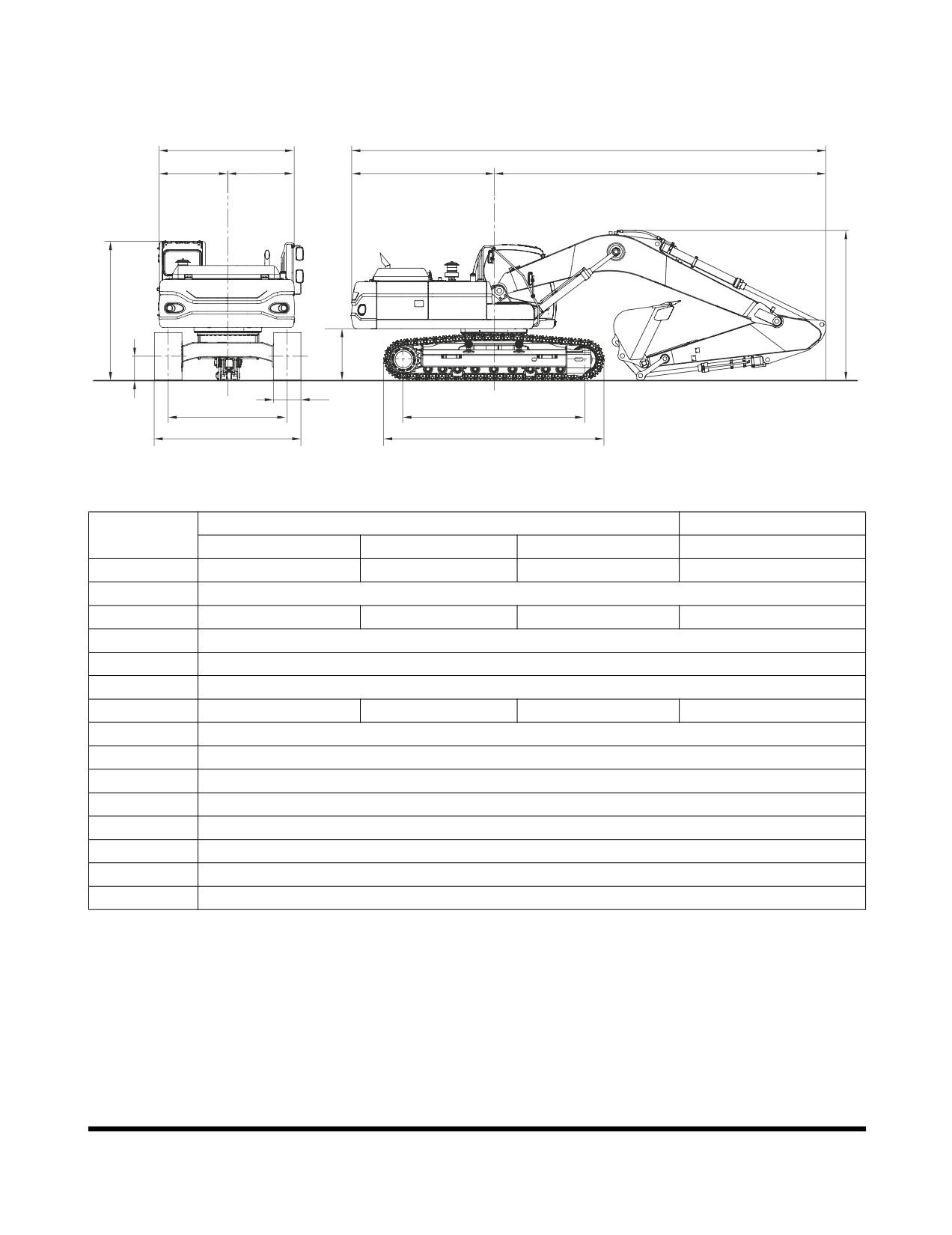
OVERALL DIMENSIONS
H
A
I
J
B
C
O
G
F
N
M
K
D
L
E
FG000316
Figure 1
6.245 m (20' 6") BOOM
10.0 m (32' 10") BOOM
DIMENSION
3.1 m (10' 2") ARM
2.5 m (8' 2") ARM
3.75 m (12' 4") ARM
7.0 m (22' 12") ARM
A
10,620 mm (34' 10")
10,740 mm (35' 3")
10,660 mm (35' 0")
14,370 mm (47' 1")
B
3,200 mm (10' 6")
C
7,420 mm (24' 4")
7,540 mm (24' 9")
7,460 mm (24' 6")
11,165 mm (36' 7")
D
4,040 mm (13' 2")
E
4,940 mm (16' 2")
F
1,150 mm (3' 10")
G
3,345 mm (10' 12")
3,475 mm (11' 5")
3,475 mm (11' 5")
3,455 mm (10' 12")
H
2,960 mm (9' 9")
I
1,500 mm (4' 11")
J
1,460 mm (4' 9")
K
2,600 mm (8' 6")
L
3,200 mm (10' 6")
M
600 mm (23.62 in)
N
500 mm (19.69 in)
O
3,065 mm (10' 1")
Specification
OP001008
7-2
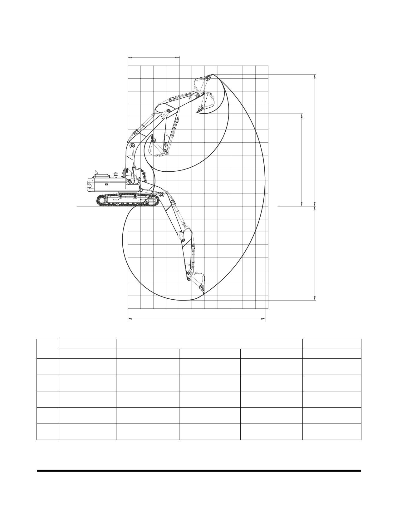
WORKING RANGE
E
11
10
9
8
7
6
5
C
4
D
3
2
1
G.L
0
0
1
2
3
4
5
6
7
8
9
10
11
-1
-2
-3
B
-4
-5
-6
-7
-8
A
Figure 2
FG000318
BOOM
6.245 m (20' 6")
10.0 m (32' 10")
DIM.
ARM
3.1 m (10' 2")
2.5 m (8' 2")
3.75 m (12' 4")
7.0 m (22' 12")
Max. Digging
A
10,745 mm (35' 3")
10,170 mm (33' 4")
11,270 mm (36' 12")
17,520 mm (57' 6")
Reach
Max. Digging
B
7,360 mm (24' 2")
6,760 mm (22' 2")
8,010 mm (26' 3")
13,855 mm (45' 5")
Depth
Max. Digging
C
10,330 mm (33' 11")
9,970 mm (32' 8")
10,410 mm (34' 2")
14,175 mm (46' 6")
Height
Max. Loading
D
7,260 mm (23' 10")
6,930 mm (22' 9")
7,365 mm (24' 2")
11,950 mm (39' 2")
Height
Min. Swing
E
4,050 mm (13' 3")
4,095 mm (13' 5")
4,065 mm (13' 4")
6,125 mm (20' 1")
Radius
Specification
OP001008
7-3
APPROXIMATE WEIGHT OF
WORKLOAD MATERIALS
IMPORTANT
Weights are approximations of estimated average volume
and mass. Exposure to rain, snow or ground water; settling
or compaction due to overhead weight and chemical or
industrial processing or
changes due to thermal or
chemical transformations
could
all
increase value of
weights listed in table.
LOW WEIGHT OR
MEDIUM WEIGHT OR
HIGH WEIGHT OR
DENSITY
DENSITY
DENSITY
MATERIAL
1,100 KG/M3
1,600 KG/M3
2,000 KG/M3
(1,850 LB/YD3), OR
(2,700 LB/YD3), OR
(3,370 LB/YD3), OR
LESS
LESS
LESS
3
401 kg/m
Charcoal
---------------------
---------------------
(695 lb/yd3)
3
433 kg/m
Coke, blast furnace size
---------------------
---------------------
(729 lb/yd3)
3
449 kg/m
Coke, foundry size
---------------------
---------------------
(756 lb/yd3)
3
801 kg/m
Coal, bituminous slack, piled
---------------------
---------------------
(1,350 lb/yd3)
3
881 kg/m
Coal, bituminous r. of m., piled
---------------------
---------------------
(1,485 lb/yd3)
3
897 kg/m
Coal, anthracite
---------------------
---------------------
(1,512 lb/yd3)
3
1,009 kg/m
Clay, DRY, in broken lumps
---------------------
---------------------
(1,701 lb/yd3)
3
1,746 kg/m
Clay, DAMP, natural bed
---------------------
---------------------
(2,943 lb/yd3)
3
1,506 kg/m
Cement, Portland, DRY granular
---------------------
---------------------
(2,583 lb/yd3)
3
1,362 kg/m
Cement, Portland, DRY clinkers
---------------------
---------------------
(2,295 lb/yd3)
3
1,522 kg/m
Dolomite, crushed
---------------------
---------------------
(2,565 lb/yd3)
3
1,202 kg/m
Earth, loamy, DRY, loose
---------------------
---------------------
(2,025 lb/yd3)
3
1,522 kg/m
Earth, DRY, packed
---------------------
---------------------
(2,565 lb/yd3)
3
1,762 kg/m
Earth, WET, muddy
---------------------
---------------------
(2,970 lb/yd3)
Specification
OP001008
7-4
LOW WEIGHT OR
MEDIUM WEIGHT OR
HIGH WEIGHT OR
DENSITY
DENSITY
DENSITY
MATERIAL
1,100 KG/M3
1,600 KG/M3
2,000 KG/M3
(1,850 LB/YD3), OR
(2,700 LB/YD3), OR
(3,370 LB/YD3), OR
LESS
LESS
LESS
3
961 kg/m
Gypsum, calcined, (heated, powder)
---------------------
---------------------
(1,620 lb/yd3)
3
1,522 kg/m
Gypsum, crushed to 3 inch size
---------------------
---------------------
(2,565 lb/yd3)
3
1,810 kg/m
Gravel, DRY, packed fragments
---------------------
---------------------
(3,051 lb/yd3)
3
1,922 kg/m
Gravel, WET, packed fragments
---------------------
---------------------
(3,240 lb/yd3)
3
1,282 kg/m
Limestone, graded above 2
---------------------
---------------------
(2,160 lb/yd3)
Limestone, graded
1,362 kg/m3
---------------------
---------------------
1-1/2 or 2
(2,295 lb/yd3)
3
1,522 kg/m
Limestone, crushed
---------------------
---------------------
(2,565 lb/yd3)
3
1,602 kg/m
Limestone, fine
---------------------
---------------------
(2,705 lb/yd3)
3
1,282 kg/m
Phosphate, rock
---------------------
---------------------
(2,160 lb/yd3)
3
929 kg/m
Salt
---------------------
---------------------
(1,566 lb/yd3)
3
529 kg/m
Snow, light density
---------------------
---------------------
(891 lb/yd3)
3
1,522 kg/m
Sand, DRY, loose
---------------------
---------------------
(2,565 lb/yd3)
3
1,922 kg/m
Sand, WET, packed
---------------------
---------------------
(3,240 lb/yd3)
3
1,362 kg/m
Shale, broken
---------------------
---------------------
(2,295 lb/yd3)
3
529 kg/m
Sulphur, broken
---------------------
---------------------
(1,620 lb/yd3)
Specification
OP001008
7-5
Specification
OP001008
7-6
1INDEX
Numerics
Teeth and Side Cutters 4-21
1,000 Hour / 6 Month Service 4-43
Tooth 4-67
10 Hour / Daily Service 4-14
12,000 Hour / 6 Year Service 4-57
C
2,000 Hour / Yearly Service 4-49
Cabin Light 2-55
250 Hour / Monthly Service 4-27
Cabin Storage Compartments 2-65
4,000 Hour / Biennial Service 4-56
Cabin Work Light Switch 2-12
50 Hour / Weekly Service 4-24
Ceiling Cover 2-61
500 Hour / 3 Month Service 4-35
Charge Warning Light 2-24
Check and Confirmation After Stopping Engine
A
3-12
Abnormal State Warning Symbols 2-29
Cigarette Lighter 2-15
Adjust Valve Clearance 4-55
Circuit Breaker 2-55
Air Intake System 4-22
Clock 2-23, 2-38
Outer Element of Air Cleaner 4-39
Cold Weather Hydraulic System Warm-up 3-10
Replace Outer Air Cleaner Element 4-50
Cold Weather Starting 3-6
Alternator and Starter 4-55
Communication
Antifreeze Concentration Tables 4-77
Error Warning 2-28
Antivibration Shock Mounts 4-55
Indicator 2-27
Arm and Bucket Joint Pins 4-24
Component Locations 2-2
Ashtray 2-65
Constant Speed Button 2-14
Audio Control Panel 2-10
Coolant Temperature Warning Light 2-25
Auto Idle Mode 3-20
Cooling System
Auto Idle Selection 2-47
Clean Radiator, Oil Cooler and Air Conditioner
Auto Idle Selector Button 2-34
Condenser Coil 4-38
Auxiliary Mode Switch 2-9
Engine 4-75
Engine Coolant Temperature Warning Light
2-25
B
Oil Cooler Dust Net 4-20
Batteries 4-34
Radiator Coolant 4-51
Battery 4-71
Refill Cooling System 4-20
Box Door 2-68
Cracks and Faulty Welds 4-22
Electrolyte Level 4-72
Cup Holder 2-67
Terminals 4-72
Cycle Time Tests 4-55
Voltage 2-28
Bolt and Nut Inspection 4-59
D
Boom and Arm Joint Pins 4-27
Boost Mode 3-21
Description of Lubrication and Service Chart 4-10
Booster Button 2-17
Digital Clock 2-23
Booster Cable 3-7
Display Selection 2-37
Bucket 4-67
Display Selector Button 2-36
Installation 4-69
Door Side Latch 2-64
O-ring 4-68
Door Window Holder 2-67
Shimming Procedures 4-69
Down Arrow Button 2-36
Shimming Procedures for Installed Bucket 4-70
Index
950106-00077E
8-1
E
Engine Coolant Temperature Gauge 2-22
Economy Mode Selection 2-46
Fuel Gauge 2-22
Economy Mode Selector Button 2-33
Hour Meter 2-24
Electrical System 4-71, 6-1
Hydraulic Oil Temperature 2-23
Engine 6-2
Multifunction Gauge 2-23, 2-27
Adjust Valve Clearance 4-55
General Venting 4-84
Check and Adjust Engine 4-48
Check Warning Light 2-25
H
Coolant Temperature Gauge 2-22
Handling a New Excavator 3-1
Coolant Temperature Warning Light 2-25
Handling of Accumulator 4-80
Cover 2-68
Hanger 2-66, 2-67
Emergency Stop Switch 2-9
Head Bolt Torques 4-55
Fan Belt 4-29, 4-30
Headlight Switch 2-11
Head Bolt Torques 4-55
Heater and Air Conditioner 2-48
Oil and Filter 4-26, 4-33
Additional Operating Instruction 2-53
Oil Level 4-14
Control Panel 2-13, 2-49
Oil Pressure Warning Light 2-24
Filter 4-36, 4-47
Shutdown 3-11
Location of Controls and Vents 2-48
Speed 2-28
Memory Function of Used Mode 2-53
Speed Control Dial 2-8
Refrigerant 4-48
Start 3-4
System 4-58
Start and Stop 3-2
Horn Button 2-17
ESC Button 2-37
Hose Clamps 4-34
Excavator Rated Lift Capacity Tables 1-46
Hour Meter 2-24
Hydraulic System 6-3
F
Flow Control 2-44
Fan Belt 4-26
Front Hydraulic Pump Pressure 2-29
Filter / Oil Info 2-39
General Venting 4-84
Filter State 2-29
Hydraulic Breaker 3-32
Flow Control 2-44
Hydraulic Hoses and Tubing 3-32
Flow Control Button 2-34
Oil and Filter 3-36
Front
Operation 3-33
Bottom Window 2-63
Selection 3-32
End Attachments 4-34
Hydraulic Cylinders 4-83
Hydraulic Pump Pressure 2-29
Hydraulic Oil Exchange 4-53
Upper Windows 2-62
Hydraulic Oil Return Filter 4-34, 4-44
Windows 2-62
Hydraulic Oil Tank 4-15
Fuel
Hydraulic Oil Temperature Gauge 2-23
Filter 4-42
Leaks in the Hydraulic System 4-16
Gauge 2-22
Main System Pump 4-83
Heater Switch 2-16
Oil Exchange 4-53
Level 4-17
Rear Hydraulic Pump Pressure 2-29
System 4-42
Swing Motor 4-84
Transfer Pump 4-78
Warm-up 3-9
Tank Drain Valve 4-26
Transfer Pump 4-78
I
Fuse
Indicator
Boxes 2-56, 4-73
Communication Indicator 2-27
Fuses 4-73
Indicator Lights
Fusible Link 2-56
Charge Warning Light 2-24
Identification 4-74
Coolant Temperature Warning Light 2-25
Engine Check Warning 2-25
G
Engine Oil Pressure Warning Light 2-24
Gauges
Preheating Indicator Light 2-26
Index
950106-00077E
8-2
Work Light 2-26
High Altitudes 3-45
Inspecting Engine Before Starting 3-2
Rainy or Humid Conditions 3-44
Inspection, Maintenance and Adjustment 4-1
Salt Water Areas 3-44
Instrument Panel 2-18, 2-20
Operation of All Switches 4-22
Intermittent Speed Button 2-14
Operation Selection Display 2-46
Operation Under Unusual Conditions 3-42
Operational Checks Before Starting Engine 3-3
L
Operational Controls and Panels 2-6
Language 2-38
Operator's Area 2-4
Leaks in the Fuel System 4-17
Operator's Compartment Light 2-55
Leaks in the Hydraulic System 4-16
Outer Air Cleaner Element 4-50
Levers
Outer Element of Air Cleaner 4-39
Adjusting Reclining 2-58
Overall Dimensions 7-2
Adjusting the Seat Forward 2-57
Overload Warning Switch (Optional) 2-16
Adjusting the Seat's Angle 2-57
Angle Adjustment of Armrest 2-58
Safety Lever 2-18
P
Lifting 3-40
Panels
Lifting With Sling 5-5
Air Conditioner Control Panel 2-13
Lights
Audio Control 2-10
Cabin 2-55
Heater and Air Conditioner 2-48
Loading and Unloading 5-1
Heater and Air Conditioner Control Panel 2-49
Locations of Safety Labels 1-4
Instrument 2-18
Long Term Storage 4-85
Instrument Panel 2-20
Lubrication and filters 3-2
Wiper Switch 2-13
Lubrication and Service Chart 4-8
Parking Excavator 3-30
Password
Activated 2-21
M
Set Password 2-42
Magnetic Clutch 4-58
Password Activated 2-21
Main Menu 2-35
Photo Sensor 2-19
Maintenance in Special Conditions 4-87
Pilot Cutoff Switch 2-55
Maintenance Intervals 4-12
Pilot Filter 4-34, 4-45
Miscellaneous Access Doors 2-68
Pins and Bushings 4-34
Mode Selection 3-19
Power Boost Selection 2-47
Mode Selector Buttons 2-33
Power Mode 3-19
Multifunction Gauge 2-23, 2-27
Power Mode Selection 2-46
Power Mode Selector Button 2-33
N
Power Socket 2-15
Nuts and Bolts 4-34
Preheating Light 2-26
Preliminary Work Machine Setup for Maintenance
O
4-4
Oil Cooler Dust Net 4-20
Preventive Maintenance 4-1
Oil Level of Travel Reducer 4-31
Pump Pressure
OP001006 5-1
Front Pump 2-29
Opening the Window 2-62
Rear Pump 2-29
Operating
Controls 2-1
Q
Instructions 3-19
Quick Clamp Switch (Optional) 2-9
Precautions 3-25
Techniques 3-40
R
Operation 3-1
Radiator Coolant 4-51
Operation In
Rear Hydraulic Pump Pressure 2-29
Extreme Cold 3-42
Refill Cooling System 4-20
Extreme Heat 3-43
Rotating Buttons 2-17
Index
950106-00077E
8-3
S
Gear and Pinion 4-35
Safety 1-1
Motor 4-84
Safety Lever 2-18, 3-13
Reduction Device 4-19, 4-32, 4-43, 4-49
Safety Precautions 4-3
System 6-4
Seat 2-57
Switches
Seat Adjustment
Auto Idle Selector Button 2-34
Adjusting Reclining 2-58
Automatic Travel Speed Control 3-14
Adjusting the Seat Forward 2-57
Auxiliary Mode 2-9
Adjusting the Seat's Angle 2-57
Booster Button 2-17
Adjustment of Lumbar Support 2-58
Cabin Work Light Switch 2-12
Air Suspension Seat 2-60
Cigar Lighter 2-15
Angle Adjustment of Armrest 2-58
Constant Speed Button 2-14
Headrest 2-58
Display Selector Button 2-36
Left ad Right Control Stand Location 2-60
Down Arrow Button 2-36
Left and Right Control Stand Elevation Height
Economy Mode Selector Button 2-33
2-60
Engine Emergency Stop 2-9
Seat Belt 2-59, 4-22
Engine Speed Control 3-19
Seat Warmer Switch (Optional) 2-16
Engine Speed Control Dial 2-8
Selection Button 2-36
ESC Button 2-37
Selection of
Flow Control Button 2-34
Breaker 2-46
Fuel Heater 2-16
Overload Alarm 2-47
Headlight Switch 2-11
Power Boost Selection 2-46, 2-47
Horn Button 2-17
Shear 2-46
Intermittent Speed Button 2-14
Serial Numbers 4-2
Overload Warning (Optional) 2-16
Set Password 2-42
Pilot Cutoff Switch 2-55
Setting Clock 2-38
Power Mode Selector Button 2-33
Shear Buttons 2-18
Power Socket 2-15
Shimming Procedures for Installed Bucket 4-70
Quick Clamp (Optional) 2-9
Shutdown
Rotating Buttons 2-17
Check and Confirmation After Stopping Engine
Seat Warmer (Optional) 2-16
3-12
Selection Button 2-36
Engine Shutdown 3-11
Shear Buttons 2-18
Parking Excavator 3-30
Starter Switch 2-8
Side Door 2-68
Travel Speed Selector Switch 2-11
Specification 7-1
Travel/Swing Alarm (Optional) 2-15
Standard Mode Selection 2-46
Up Arrow Button 2-35
Standard Specification 7-1
Warning Light 2-12
Starter Switch 2-8
Washer Button 2-14
Starting Engine Using a Booster Battery 3-7
Wiper Switch (Lower) 2-13
Start-up
Symbols
Cold Weather Hydraulic System Warm-up 3-10
Air Cleaner Clogged Warning 2-31
Cold Weather Starting 3-6
Hydraulic Oil Overheat Warning 2-30
Engine Start 3-4
Overload Warning (Optional) 2-32
Hydraulic System Warm-up 3-9
Pilot Filter Clogged Warning 2-30
Inspection Before Starting Engine 3-2
Return Filter Clogged Warning 2-31
Operational Checks Before Starting Engine 3-3
Starting Engine Using a Booster Battery 3-7
T
Stereo 2-54
Table of Recommended Lubricants 4-6
Audio Control Panel 2-10
Towing Procedure 3-31
Structural Damage 4-55
Track Assemblies 4-26
Suction Strainer 4-53
Track Tension 4-81
Sun Visor 2-66
Transportation 5-1
Swing
Travel 3-14
Bearing 4-25
Index
950106-00077E
8-4
Control Lever Operation 3-15
W
Instructions 3-16
Warning Light Switch 2-12
Reduction Device 4-31, 4-32, 4-46
Washer Button 2-14
Speed Selector Switch 2-11
Water Separator 4-18
System 6-5
Weight of Workload Materials 7-4
Travel/Swing Alarm Switch (Optional) 2-15
Window Washer Liquid 4-21
Troubleshooting 6-1
Windows
Door Window Holder 2-67
U
Front 2-62
Unloading and Loading 5-1
Front Bottom 2-63
Up Arrow Button 2-35
Front Upper 2-62
Opening 2-62
Sun Visor 2-66
V
Wiper Switch (Lower) 2-13
Venting and Priming Hydraulic System 4-83
Wiper Switch Panel 2-13
General Venting 4-84
Work Levers (Joysticks) (ISO Style) 3-22
Hydraulic Cylinders 4-83
Work Light Indicator Light 2-26
Main System Pump 4-83
Working Range 7-3
Swing Motor 4-84
Index
950106-00077E
8-5