Doosan Mega 500-V (TIER II). Operation and Maintenance Manual (2001) - page 3
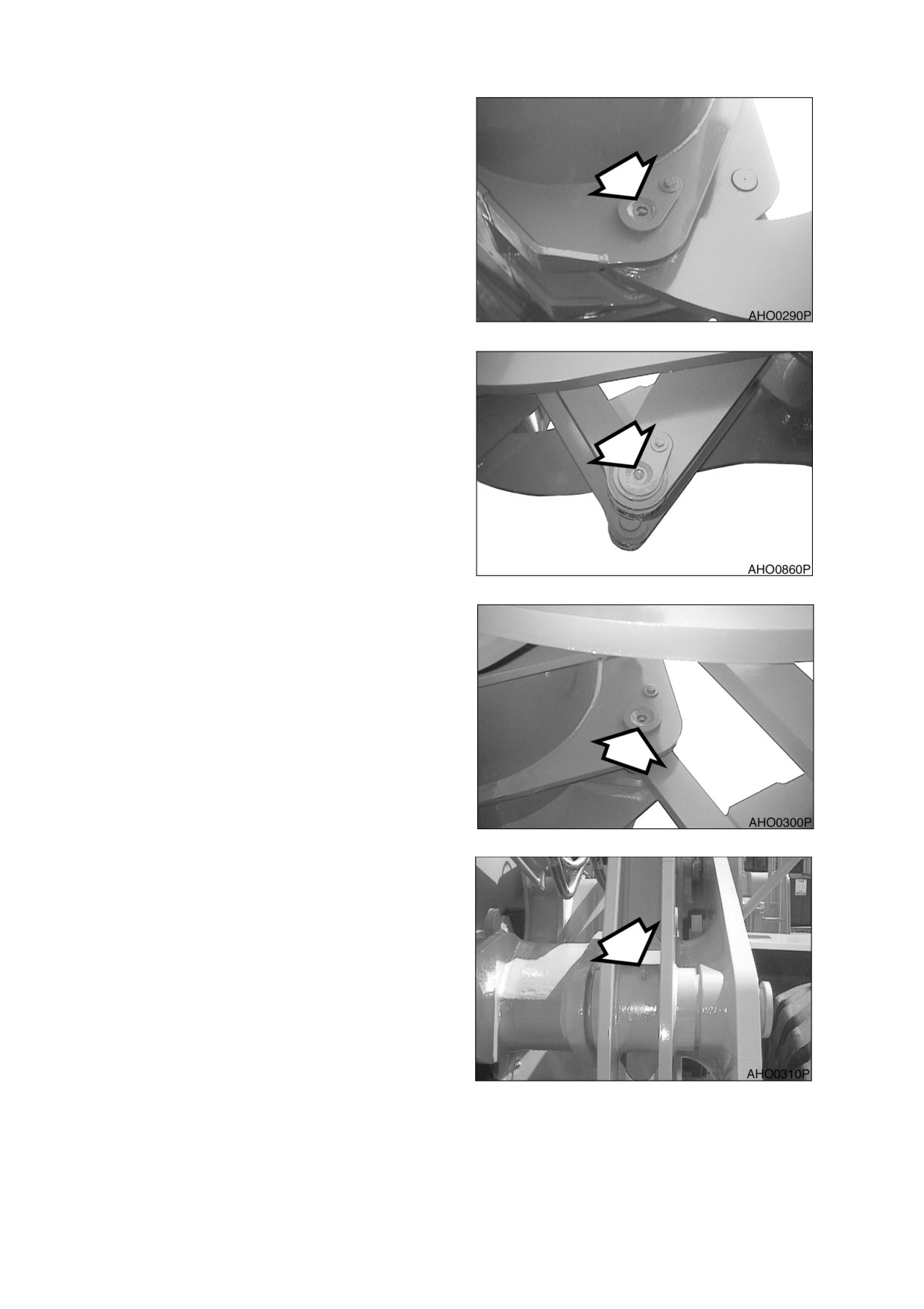
A: Bucket hinge pins, 2 locations (Figure
27).
Figure 27
Lever link connecting pins,
2
locations (Figure 28).
Figure 28
Bucket link connecting pins,
2
locations (Figure 29).
Figure 29
B: Arm lever connecting pins (left, right),
2 locations. (Figure 30)
Figure 30
022-00029AE Operation and Maintenance Manual
Inspection, Maintenance and Adjustment 4-19
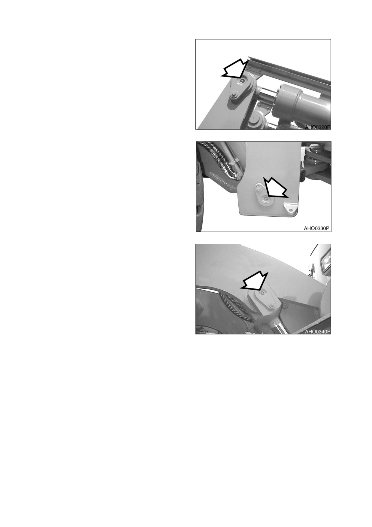
C: Bucket cylinder rod ends, 2 locations.
(Figure 31)
Figure 31
D: Lift cylinder heads
(left, right),
2
locations (Figure 32).
Figure 32
Lift cylinder rod ends,
2 locations.
(Figure 33)
Figure 33
4-20 Inspection, Maintenance and Adjustment
022-00029AE Operation and Maintenance Manual
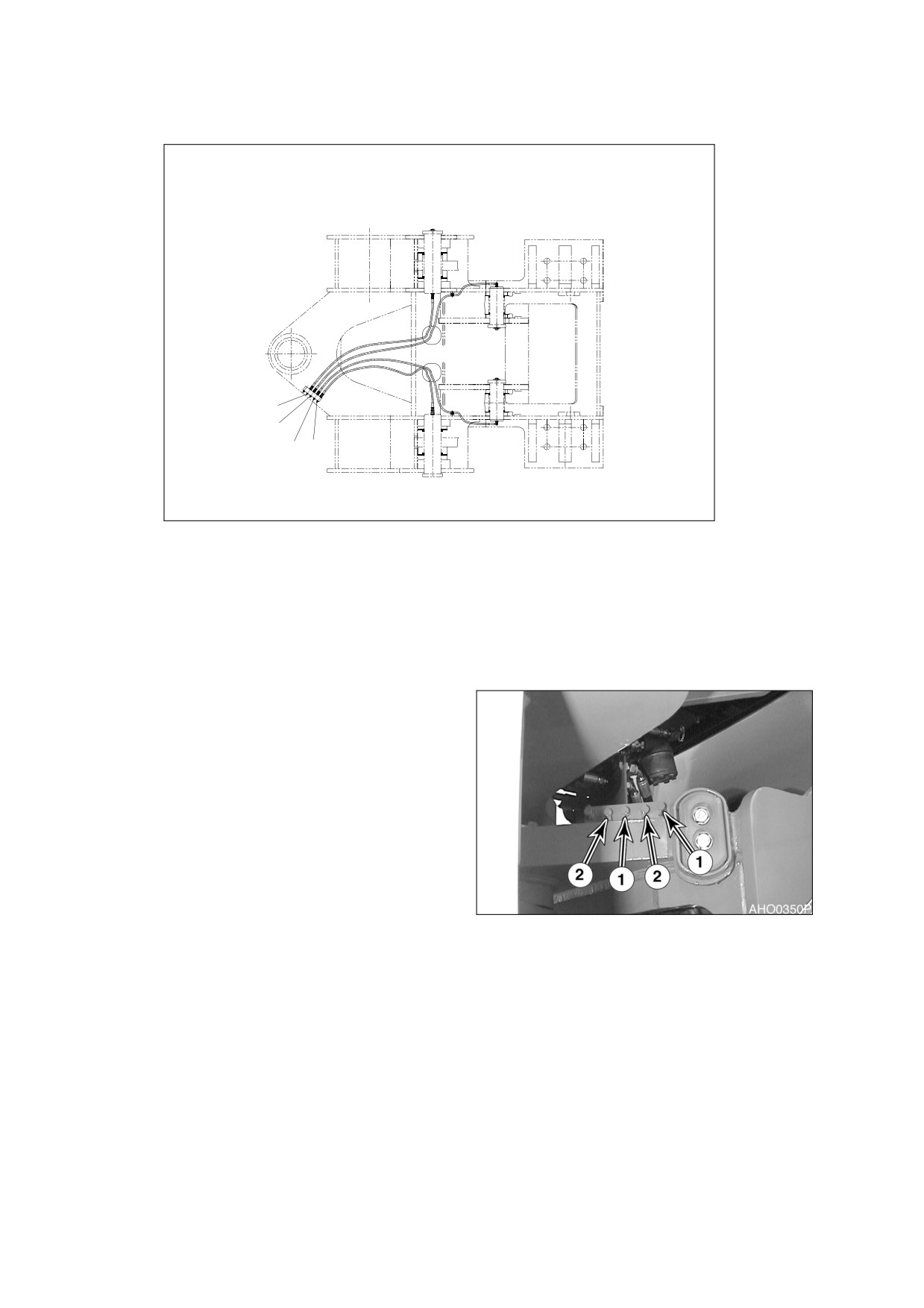
E: Remote location points
2
1
2
1
HA503041
Figure 34
1.
REMOTE FITTINGS FOR BUCKET
2.
REMOTE FITTINGS FOR LOADER ARM
CYLINDER HEADS (50 HOUR) (Figure 35
FOOT ENDS (50 HOUR) (Figure 35 and
and Figure 36)
Figure 37)
Figure 35
022-00029AE Operation and Maintenance Manual
Inspection, Maintenance and Adjustment 4-21
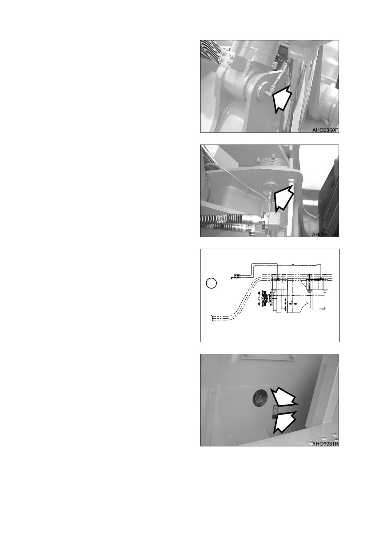
1)
Bucket cylinder heads
(left,
right),
2 points. Greased from
two remote grease points
(1,
Figure 34).
Figure 36
2)
Loader arm foot ends,
2
locations on each side of
machine. Greased from two
remote grease points (2, Figure
34).
Figure 37
F: Grease Rear Axle Pivot
Rear Axle pivot
(1, Figure
38),
2
locations on each side of machine.
Use remote grease fittings mounted
1
on frame shown in Figure 38.
AHO0390L
Figure 38
Figure 39
4-22 Inspection, Maintenance and Adjustment
022-00029AE Operation and Maintenance Manual
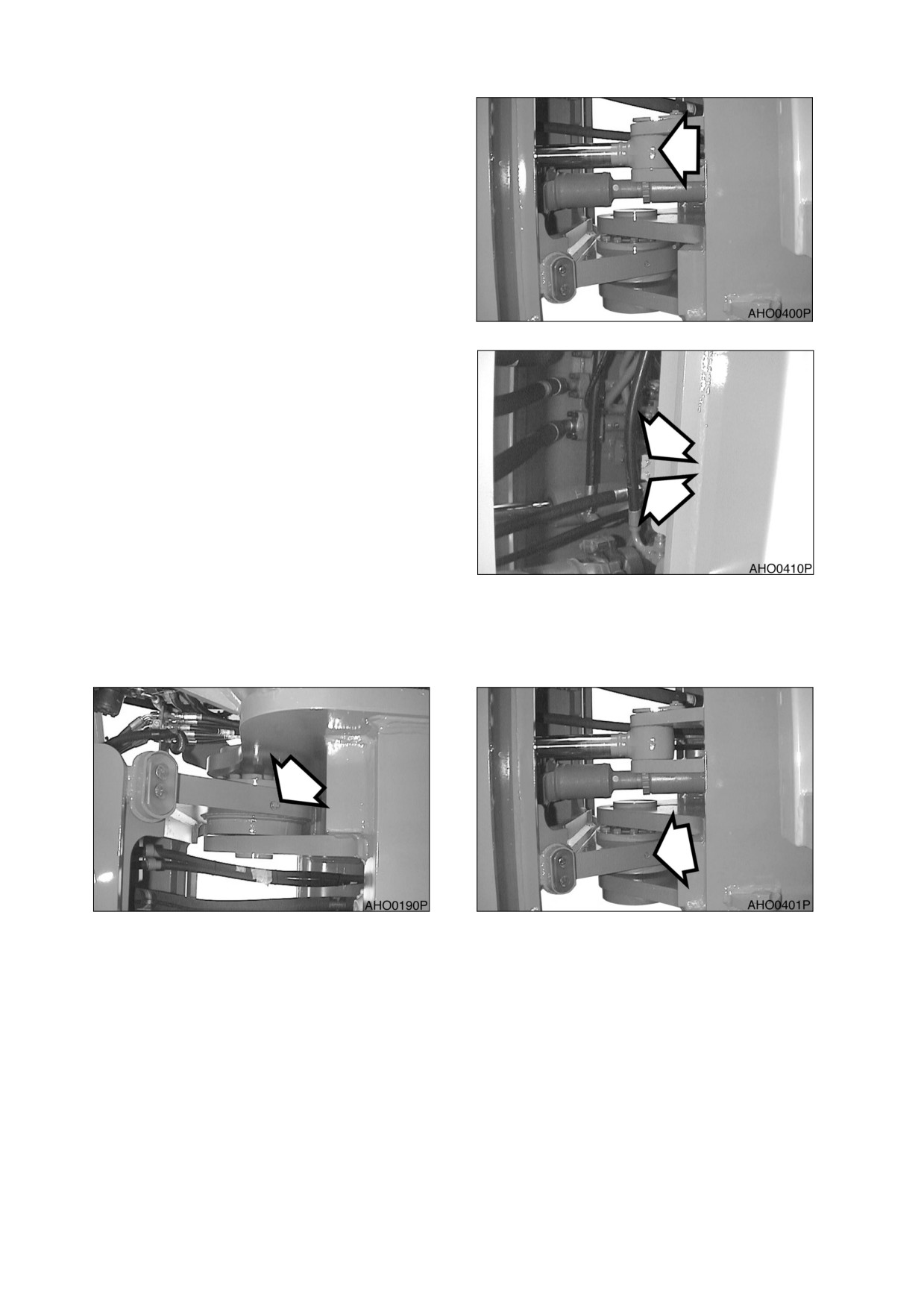
GREASE STEERING CYLINDER ROD AND
BASE ENDS
1.
Steering cylinder rods, 2 locations, one on
each side of machine.
Figure 40
2.
Steering cylinder head ends, 2 locations.
Use remote grease fittings mounted on
frame.
Figure 41
GREASE UPPER AND LOWER CENTER PINS
1.
Center pins, upper (Figure 42) and lower (Figure 43). Two locations on each side of machine.
Figure 42
Figure 43
CHANGE ENGINE OIL AND FILTER (INITIAL)
NOTE: Engine oil and filter must be changed after first 50 hours of operation to comply with new
machine break-in requirements. After first change, oil and filter should be changed every
250 hours. Follow procedure under 250 hour maintenance interval (See page 4-30).
022-00029AE Operation and Maintenance Manual
Inspection, Maintenance and Adjustment 4-23
HYDRAULIC FULL FLOW FILTER REPLACEMENT (INITIAL)
NOTE: Replace hydraulic full flow filter after first 50 hours of operation and every 250 Hours
thereafter. Follow procedure under 250 hour maintenance interval (See page 4-27)
CHECK WATER PUMP BELT TENSION - ALTERNATOR, AND AIR CONDITIONER BELT (INITIAL)
NOTE: Water pump belt tension must be checked after first 50 hours of operation to comply with
new machine break-in requirements. After first check, water pump belt must be checked
every 250 hours. Follow procedure printed under 250 hour maintenance interval (See
page 4-29).
CLEAN EXTERIOR OF RADIATOR, OIL COOLER AND AIR-CONDITIONER EVAPORATOR
1.
Dust and dirt accumulation on fins of radiator, oil cooler, and additional transmission cooler greatly
reduce their cooling efficiency. Use compressed air, water and steam to clean fins on radiator, oil
cooler, and transmission cooler.
NOTE: On an especially dusty job site, clean fins every 50 hours. On other job sites, clean fins
every 500 hours (See page 4-35).
4-24 Inspection, Maintenance and Adjustment
022-00029AE Operation and Maintenance Manual
250 HOUR / MONTHLY SERVICE
PERFORM ALL 10 HOUR / DAILY AND 50 HOUR SERVICE CHECKS
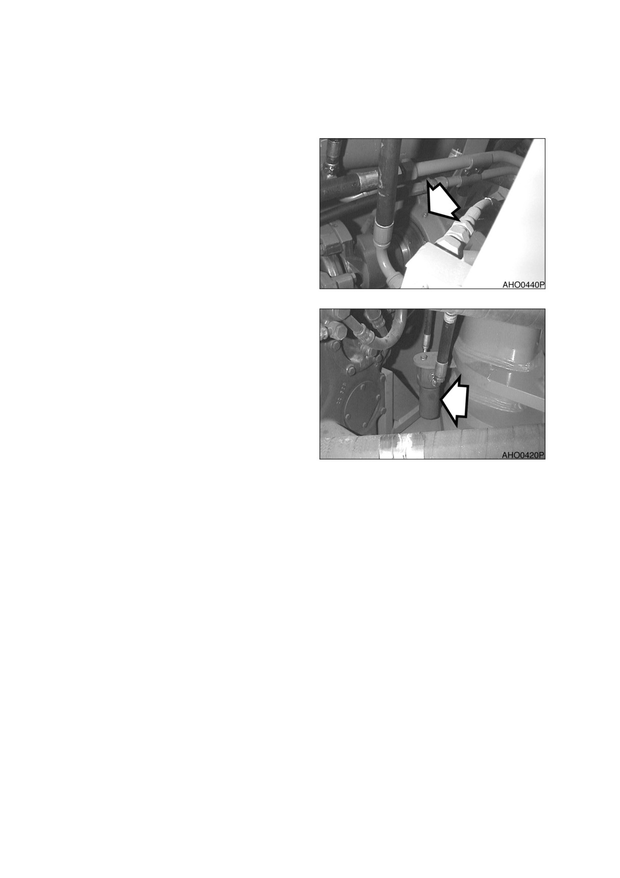
GREASE DRIVE SHAFT CENTER BEARING
1.
Grease drive shaft center bearing,
1
location. There is no remote fitting for this
bearing.
Figure 44
REPLACE HYDRAULIC SYSTEM PILOT
FILTER
Replace filter element in pilot filter. Perform the
following steps:
1.
Vent hydraulic oil tank.
Figure 45
022-00029AE Operation and Maintenance Manual
Inspection, Maintenance and Adjustment 4-25
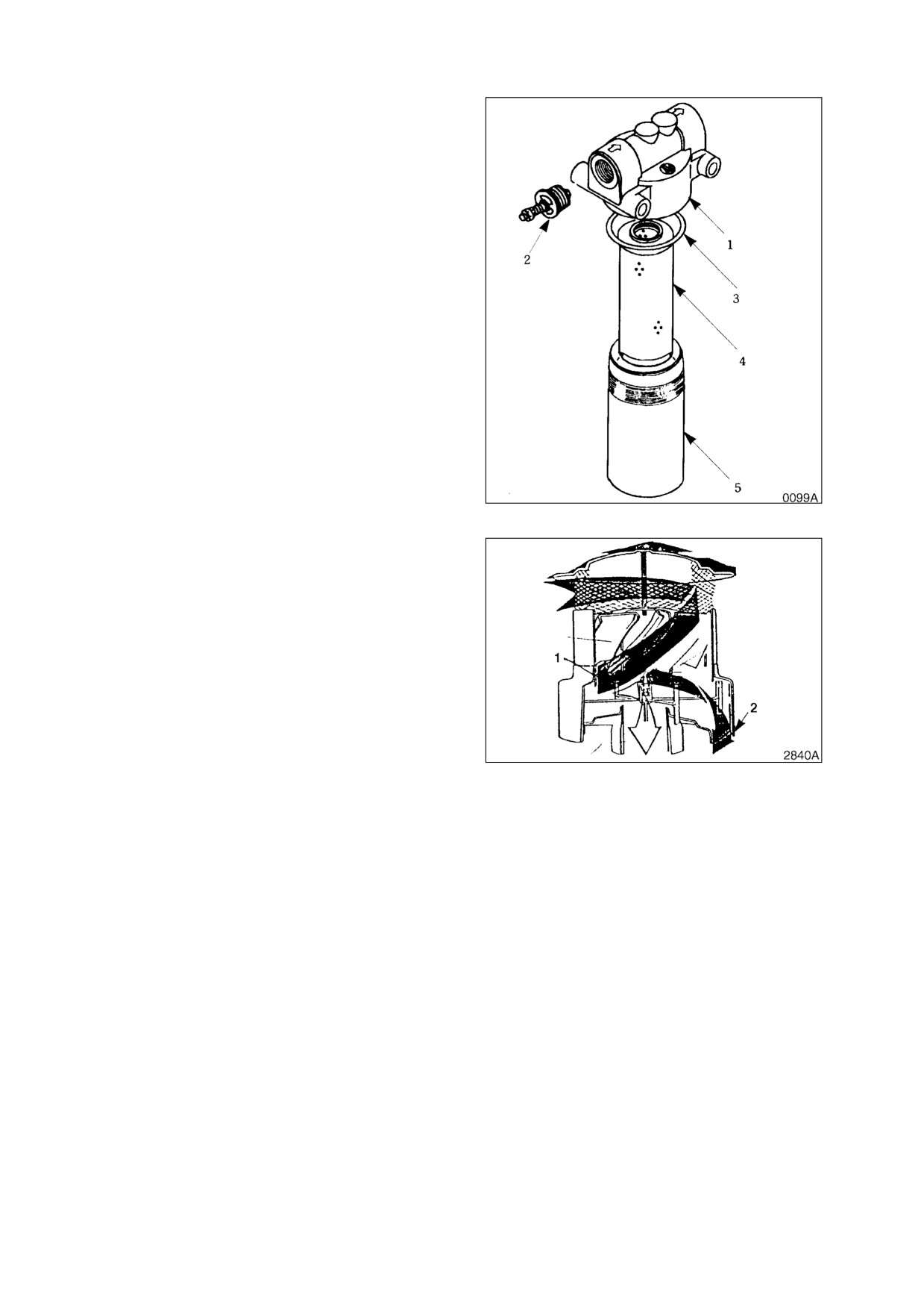
2.
Unscrew element cover (5, Figure
46).
Cover is filled with oil. Dispose of oil.
3.
Remove O-ring (3, Figure 46) and filter
element (4).
4.
Use a non flammable, non-toxic solvent to
clean out cover (5, Figure 46).
5.
Insert a new filter element (4, Figure 46)
into cover (5). Install a new O-ring (3).
6.
Screw cover (5, Figure 46) onto filter head
(1).
Figure 46
CHECK ENGINE AIR CLEANER PRE-
CLEANER
1.
The engine is equipped with a pre-cleaner.
Dust, insects, rainwater etc., can be
present in the air. The pre-cleaner collects
this material and discharges it. This
prevents material from being drawn into air
cleaner. The pre-cleaner does not need
periodic cleaning or replacement.
Figure 47
4-26 Inspection, Maintenance and Adjustment
022-00029AE Operation and Maintenance Manual
HYDRAULIC FULL FLOW FILTER REPLACEMENT
WARNING!
The hydraulic oil will be hot after normal machine operation. Allow system to cool before
attempting to service any of the hydraulic components.
The hydraulic tank is pressurized. Loosen hydraulic oil fill cap slightly to allow pressurized air to
vent. After pressure has been released, it is safe to remove either the fill cap or service covers or
drain water from the tank.
IMPORTANT!
Make sure to clean any dirt or water from top of the hydraulic tank, especially around fill port and
filter ports.
NOTE: Replace hydraulic full flow filter after first 50 hours of operation and every 250 Hours
thereafter.
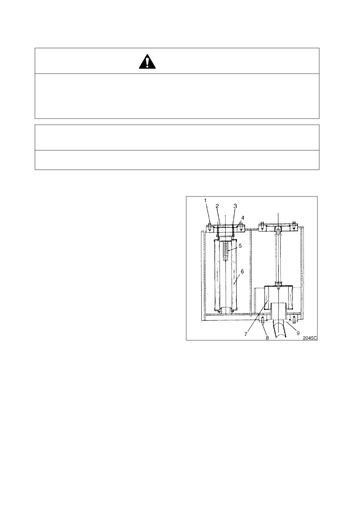
1.
Loosen breather cap on hydraulic
reservoir. (See Figure 10 on page 4-10).
2.
Clean filter cover
(2, Figure
48) and
reservoir around cover.
3.
Remove bolts (1, Figure 48) from cover
(2).
4.
Lift cover (2, Figure 48) and O-ring (4) off
reservoir. Control spring
(3) that sits
beneath cover. Remove spring (3).
5.
Remove valve (5, Figure 48) and filter
element (6) from reservoir.
6.
Clean underside of cover (2, Figure 48).
7.
Set a new element (6, Figure 48) and
valve
(5) down into reservoir. Press
element down onto its base until top of
element is approximately 4 mm (0.157 in)
below edge of reservoir.
Figure 48
8.
Install a new O-ring (4, Figure 48) on cover
(2). Set spring (3) into place on element
(6).
9.
Set cover (2, Figure 48) into place over
element (6). Install bolts (1) through cover
(2) and tighten them.
10.
Tighten breather cap on reservoir.
022-00029AE Operation and Maintenance Manual
Inspection, Maintenance and Adjustment 4-27
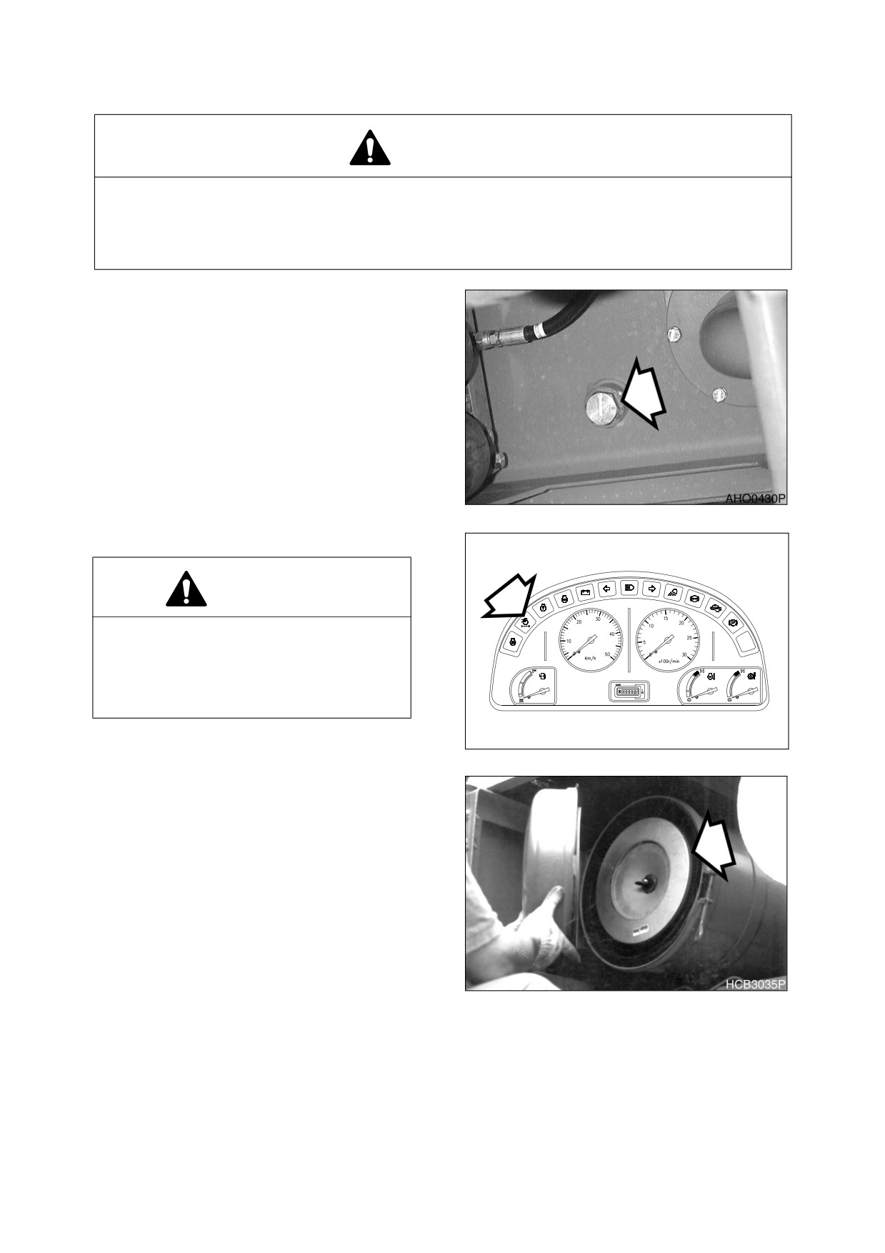
DRAIN WATER FROM HYDRAULIC OIL TANK
WARNING!
Be certain that hydraulic oil has cooled before draining water and sediment. Hot oil could splash
and cause burns.
The hydraulic tank is pressurized. Press button in center of breather to allow pressurized air to
vent. After pressure has been released, it is safe to remove either the fill cap or service covers.
1.
Position machine on firm, level ground.
Lower boom and position bucket on
ground. Turn “Off engine.
2.
Position a container under hydraulic
reservoir drain plug. Open reservoir
breather cap (See Figure 10 on page 4-
10). Loosen drain cock from bottom of
reservoir (Figure 49). Allow all water and
sediment to drain out. Tighten drain cock.
Figure 49
CLEAN AIR CLEANER
CAUTION!
Never remove air cleaner element while
engine is running. This will allow dirt to be
sucked into engine and cause serious
engine damage. Always turn engine "OFF"
before servicing air cleaner.
AQO0170L
Figure 50
1.
Locate the air filter assembly (Figure 51).
Remove access cover and remove outer
element of air filter assembly.
NOTE: If indicator light on instrument
panel comes "ON," this
indicates that air cleaner needs
to be serviced.
NOTE: Replace outer element every
1500 hours of service.
Figure 51
4-28 Inspection, Maintenance and Adjustment
022-00029AE Operation and Maintenance Manual
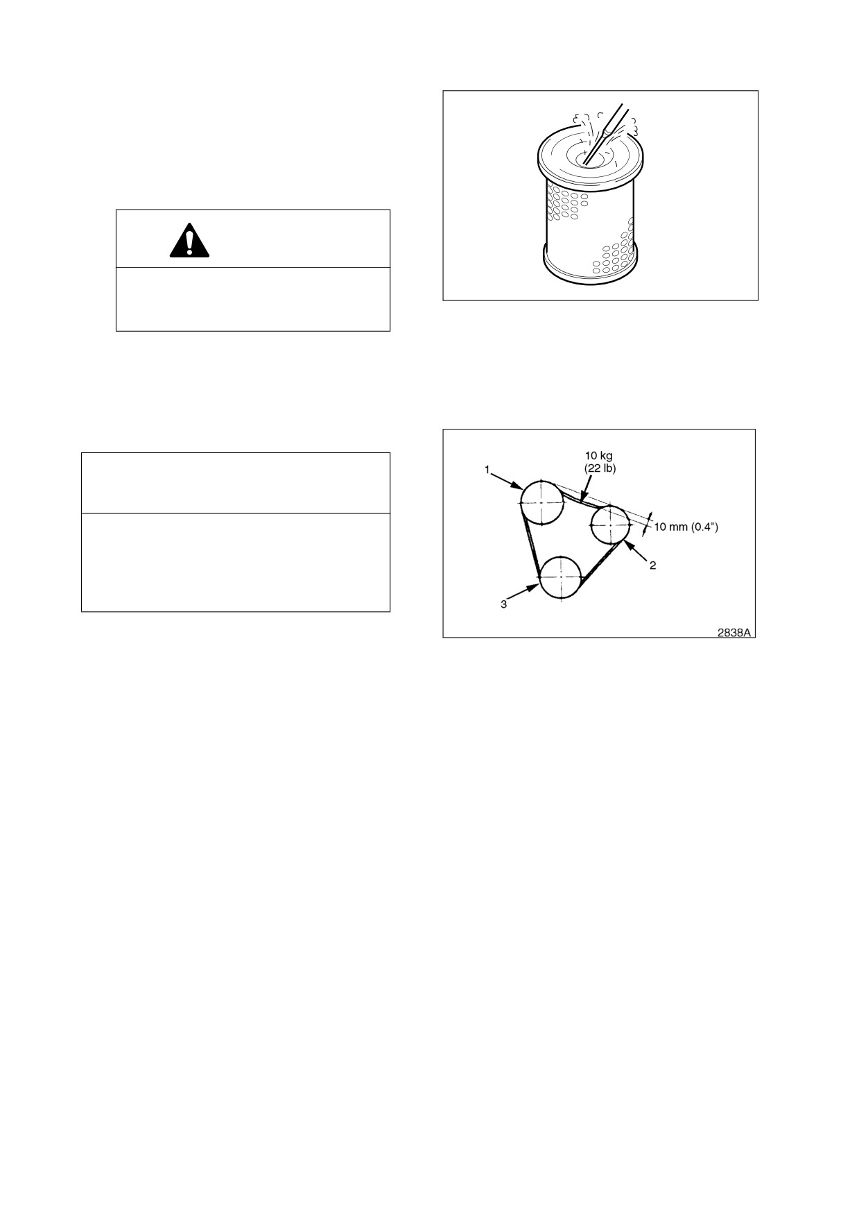
2.
Clean outer filter by blowing compressed
air from inside of filter towards the outside.
Do not use more than 205 kPa (30 psi) air
pressure.
3.
Clean the inside of air filter housing and
inside of air filter housing cover.
CAUTION!
Never clean the inside of air filter
HAOC570L
housing while the inner element is
not installed.
Figure 52
4.
Properly reinstall air filter and cover.
Tighten cover wing nut by hand. Do not
use any tools to tighten wing nut.
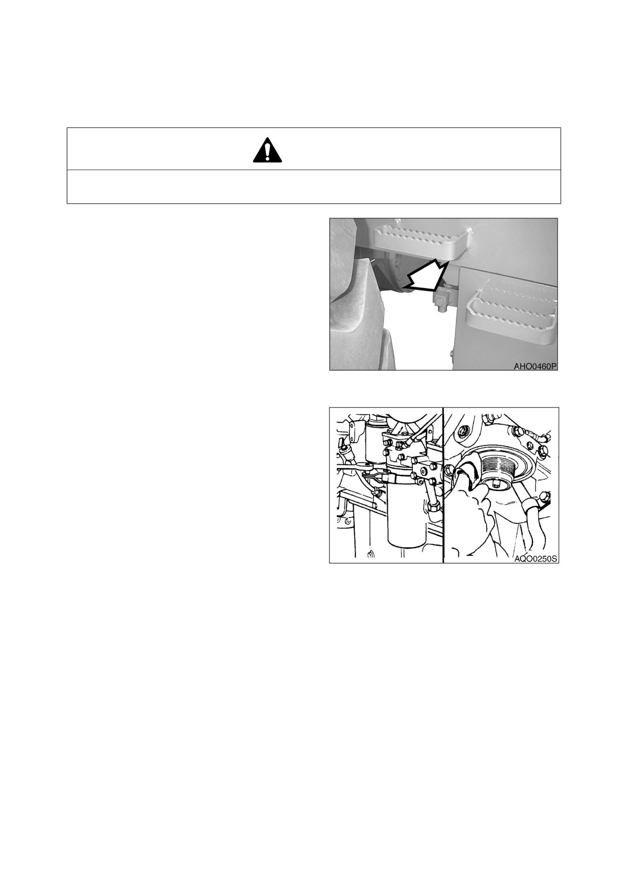
CHECK WATER PUMP BELT TENSION
IMPORTANT
A loose water pump belt can cause engine
overheating, poor charging, and/or
premature belt wear. A belt that is too tight
can cause damage to the water pump,
alternator bearing or belt.
NOTE: Water pump belt tension must
be checked after first 50 hours
Figure 53
of operation to comply with new
machine break-in requirements.
After first check, water pump
belt must be checked every 150
hours. After first tension check,
belt must be checked every 150
hours.
1.
Apply 10 kg (22 lb) of force to midpoint of water pump belt. (Figure 53). The water pump belt should
deflect 10 mm (0.4 in). If belt deflects more than this, loosen control link and move idler pulley (2) to
tighten belt tension until deflection is 10 mm (0.4 in). Inspect water pump belt for damage. If belt is
damaged, replace it.
022-00029AE Operation and Maintenance Manual
Inspection, Maintenance and Adjustment 4-29
CHANGE ENGINE OIL AND FILTER
NOTE: Engine oil and filter must be changed after first 50 hours of operation to comply with new
machine break-in requirements. After first change, oil and filter should be changed every
250 hours.
CAUTION!
Never attempt to change oil or filter on a hot engine. Hot oil could splash and cause burns. Allow
engine to cool down before changing oil or filter.
1.
Position a larger container under drain
cock beside left wall of fuel tank. Loosen
drain cock and allow all engine oil to drain
out. Tighten drain cock.
NOTE: Oil warming is good when
replacing oil. If machine is cold,
operate the engine to bring the
coolant temperature up to
about 40°C (104°F). When the
needle
of
the
coolant
temperature gauge reaches the
middle of the "WHITE ZONE,"
the temperature is about 40°C
Figure 54
(104°F).
2.
Replace engine oil filter. The engine oil
filter is a spin-on type (Figure 55). Remove
and discard filter.
3.
Install new filter, Apply a small amount of
oil around filter gasket. Screw filter on
head until gasket contacts head by hand,
turn filter
3/4~1 turn more with filter
wrench.
NOTE: See
“Fluid Capacities” on
page 4-5 for capacity.
4.
Refill engine with correct oil through oil fill
port. Refer to Lubrication Table of this
Figure 55
manual for recommended oil for the
operating conditions.
5.
Start engine and check engine oil pressure
light.
6.
Shutdown engine. Lock for signs of leaks
at filter. Recheck oil level.
4-30 Inspection, Maintenance and Adjustment
022-00029AE Operation and Maintenance Manual
REPLACE DCA4 COOLANT FILTER CARTRIDGE
CAUTION!
Pressurized radiator tank.
Spray of hot coolant can cause burn.
Stop engine and allow radiator and coolant to cool completely, then open cap slowly to relieve
pressure.
CAUTION!
Hot coolant and engine components can cause burn.
Avoid contact with coolant or engine components.
1.
Park the machine on a level surface, apply
the parking brake, lower the attachment to
the ground, and stop the engine.
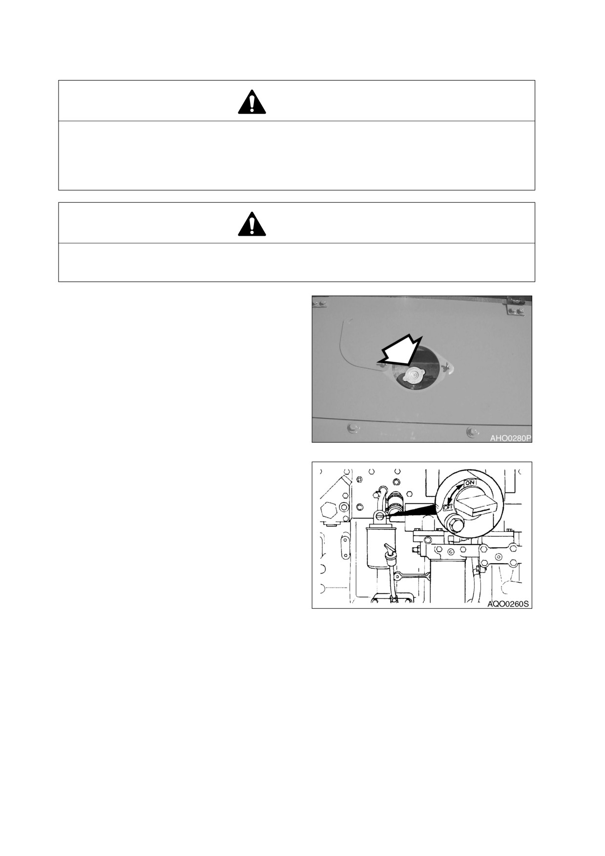
2.
Press the button on the radiator tank cap to
release any remaining pressure, and remove
the cap slowly (Figure 56).
Figure 56
3.
Turn the coolant shutoff valve "OFF."
Figure 57
022-00029AE Operation and Maintenance Manual
Inspection, Maintenance and Adjustment 4-31
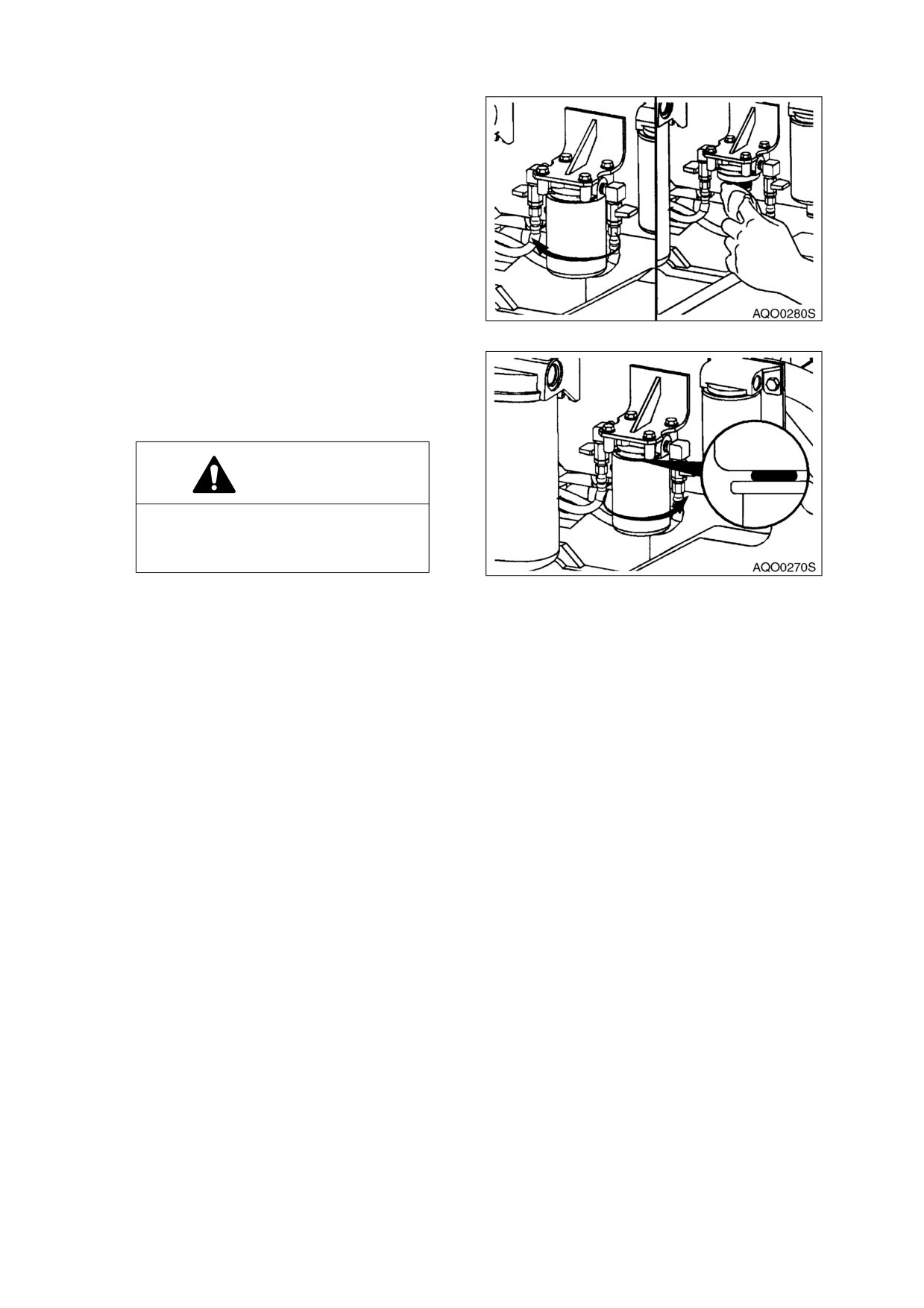
4.
Remove and properly dispose of the
coolant filter.
5.
Clean the filter head gasket surface.
6.
Apply a light film of clean engine oil to the
gasket surface of a new DCA4 coolant
filter cartridge.
Figure 58
7.
Install the filter firmly by hand. Follow the
instructions supplied with the filter.
8.
"OPEN" the coolant shutoff valve and
install the radiator cap.
CAUTION!
Severe engine damage will result if
the coolant shutoff valve is left
closed.
Figure 59
9.
Run the engine and check for coolant
leaks.
10. Idle the engine for about five minutes to
purge all air from the coolant.
11. After air has been purged from the system,
stop the engine and check the coolant
level again.
12. If needed, add required amount of the
coolant.
4-32 Inspection, Maintenance and Adjustment
022-00029AE Operation and Maintenance Manual
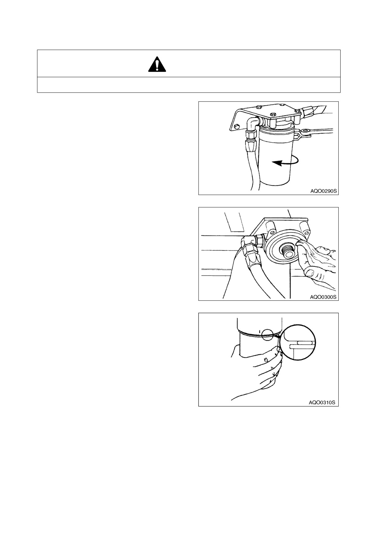
REPLACE FUEL FILTER
WARNING!
Exchange filter after waiting for engine to cool. Be careful of fire hazards. Do not smoke.
1.
Locate fuel
filter
inside
engine
compartment.
2.
Position a small container under fuel filter.
Drain filter by opening drain valve on
bottom of filter.
3.
Unscrew fuel filter from head assembly.
Discard fuel filter.
Figure 60
4.
Cleaning filter head.
Figure 61
5.
Install new fuel filter. Screw filter on head
until gasket contacts head, turn filter 1/3-1/
2 turn more.
NOTE: Coat fuel filter gasket with fuel.
NOTE: Fill fuel filter with clean fuel.
This will help reduce fuel
system priming.
6.
Start engine. After engine has run for a
couple of minutes, shutdown engine and
lock for leaks.
If engine does not start, fuel system may
Figure 63
need priming. Prime fuel system using the
following procedure:
A. Loosen plug on top of fuel filter head.
B. Unscrew and pump the hand operated primer pump near fuel injection pump. Pump primer until
fuel is present at plug hole in fuel filter head.
022-00029AE Operation and Maintenance Manual
Inspection, Maintenance and Adjustment 4-33
C. Tighten plug in fuel filter head.
D. Continue to pump primer pump until a strong resistance is felt. Screw primer pump knob back
into housing.
E. Start engine and lock for signs of leaks.
AXLE DIFFERENTIAL AND PLANETARIES OIL REPLACEMENT (INITIAL)
NOTE: The differential and planetaries oil should be drained and refilled after first 250 hours of
operation. There after every 1500 hours of operation. (See page 4-42)
CHECK DIFFERENTIAL GEAR OIL
1.
Park the machine on a level surface, apply the parking brake, lower the attachment to the ground, and
stop the engine.
2.
Remove the oil level plug from the front axle housing, using a 12 mm hex (Allen) wrench.
3.
If the oil level is lower than the plug, add the specified oil through the plug hole.
4.
Magnetic plugs are used for axle housing. Wipe off the small amount of the metallic powder that
usually sticks to the plugs. If abnormal debris is found, determine the cause and correct it. Refer to
the Shop Manual for the proper correction procedure.
5.
If there is any sign of water in the oil, drain and replace the oil. Oil containing water looks milky.
6.
Retighten the level plug.
7.
Check the rear axle level following the same steps.
CHECK PLANETARY GEAR OIL
1.
Check the oil level on all four wheels
2.
Move the machine on a level surface so that the oil level mark on the planetary gear housing comes
to the horizontal position.
3.
Turn "ON" the parking brake switch, lower the attachment to the ground, and stop the engine.
4.
Remove the oil drain plug on the housing, using a 22mm hex (Allen) wrench.
5.
If the oil level is lower than the plug, add the specified oil through the plug hole.
6.
Magnetic plugs are used for planetary gear housing. Wipe off small amount of metallic powder that
usually sticks to the plugs. If abnormal debris is found determine the cause and correct it. Refer to the
Shop Manual for the proper correction procedure.
7.
If there is any sign of water in the oil, drain and replace the oil. Oil containing water looks milky.
8.
Retighten the plug.
REPLACING TRANSMISSION OIL AND FILTER (INITIAL)
NOTE: Transmission oil and filter must be changed after first 250 hours of operation to comply
with new machine break-in requirements. After first change, oil and filter must be changed
every 1000 hours. Follow procedure under 1000 hour maintenance interval (See page
4-24).
4-34 Inspection, Maintenance and Adjustment
022-00029AE Operation and Maintenance Manual
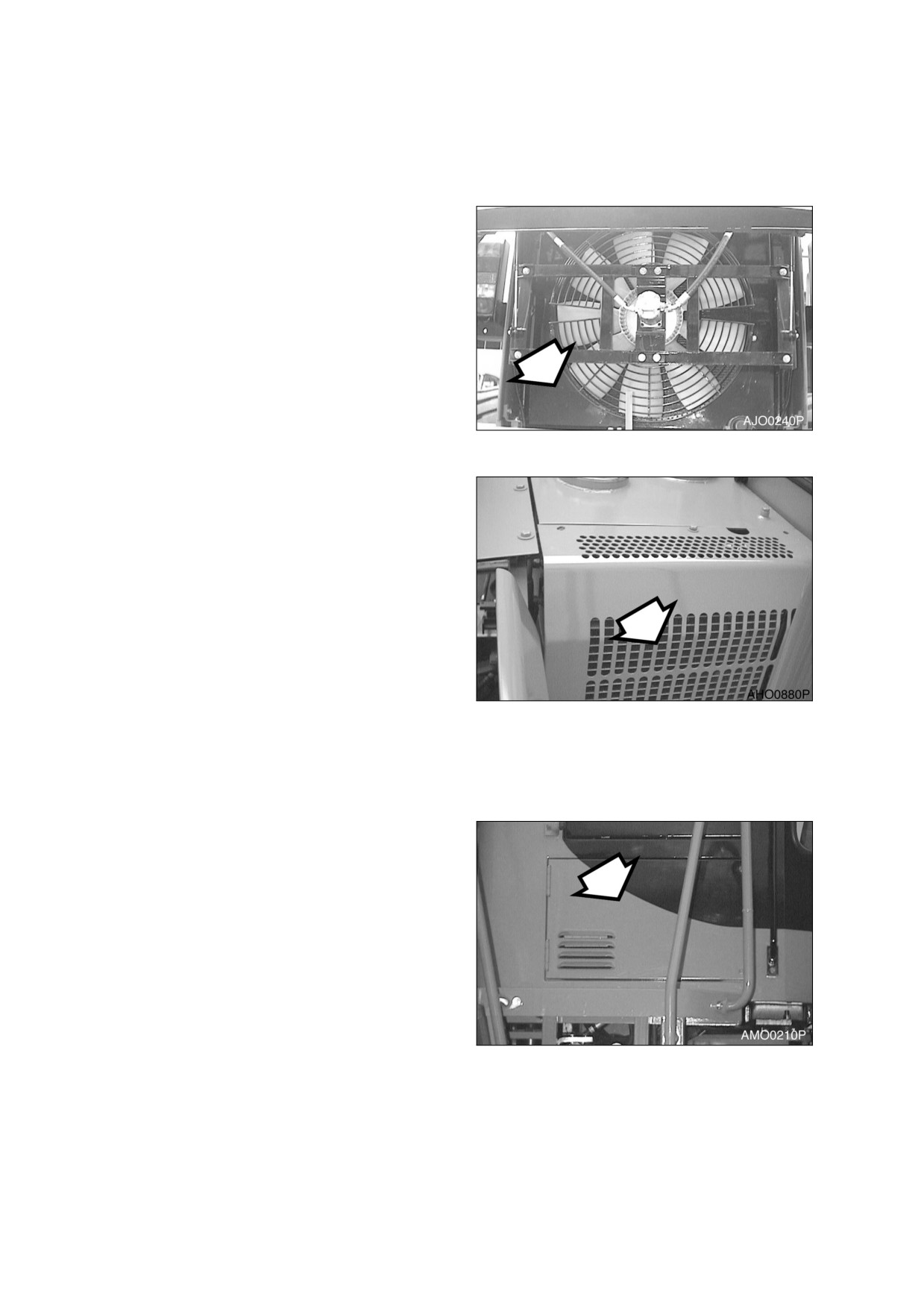
500 HOUR / 3 MONTH SERVICE
PERFORM ALL 10 HOUR / DAILY, 50, 150, AND 250 HOUR SERVICE CHECKS
CLEAN EXTERIOR OF RADIATOR, OIL
COOLER AND AIR-CONDITIONER
EVAPORATOR
1.
Dust and dirt accumulation on fins of
radiator, oil cooler, and additional
transmission cooler greatly reduce their
cooling efficiency. Use compressed air,
water and steam to clean fins on radiator,
oil cooler, and transmission cooler.
NOTE: On an especially dusty job site,
clean fins every 50 hours. On
other job sites, clean fins every
Figure 64 RADIATOR AND OIL COOLER
500 hours.
Figure 65 AIR-CONDITIONER EVAPORATOR
CLEAN AIR CONDITIONING FILTER
The unit is equipped with an air filtration system which filters out dirt and dust particles from air being
circulated into operator’s cab. The air conditioning filter is in the right side switch panel console.
1.
Open access cover on the lower right side
of cab on the outside to gain access to
filter.
Figure 66
022-00029AE Operation and Maintenance Manual
Inspection, Maintenance and Adjustment 4-35
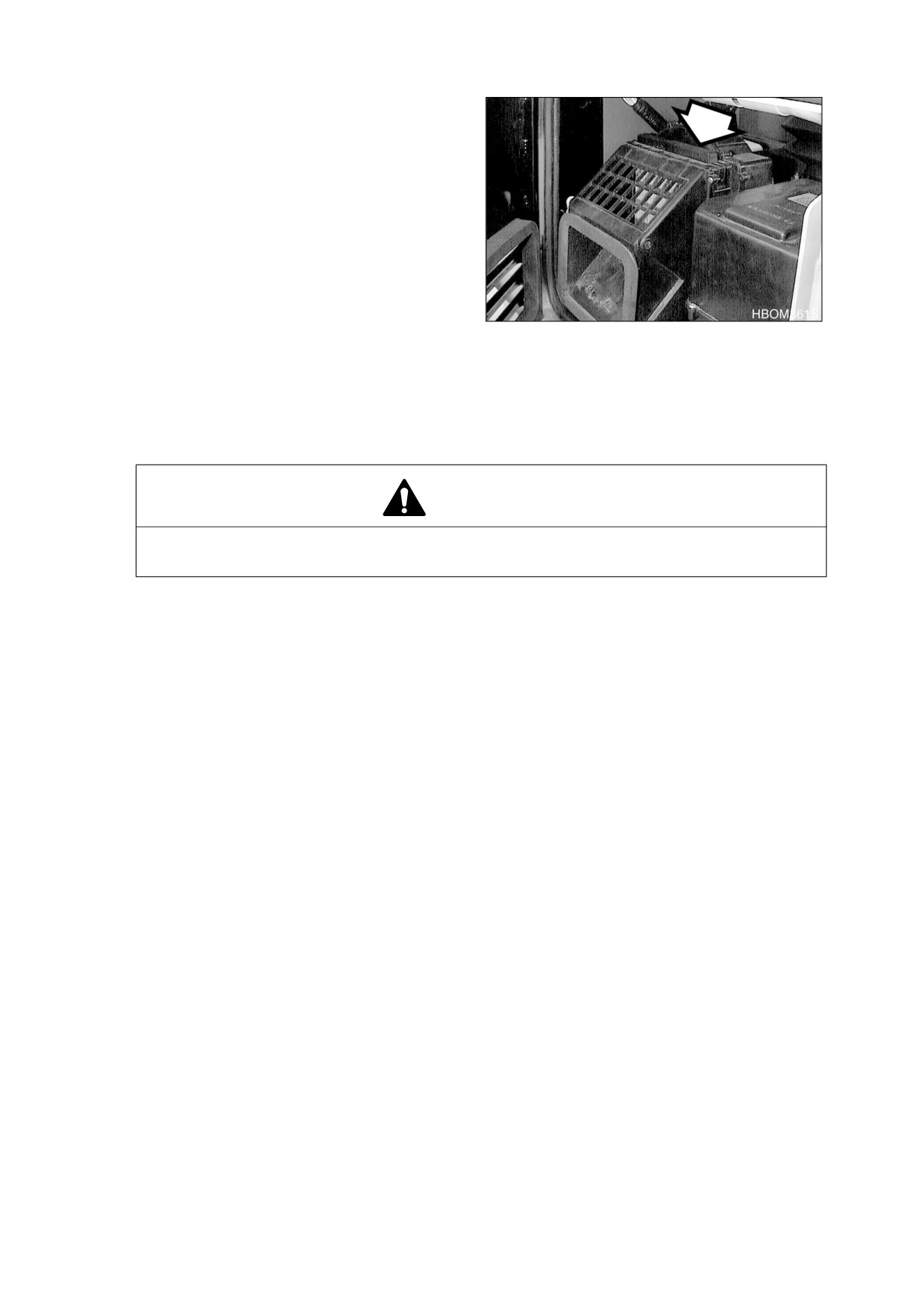
2.
Remove filter element and inspect it for
damage.
3.
Use compressed air to clean filter element.
If element is very dirty use a mild soap and
water solution to clean it.
Figure 67
NOTE: If water was used to clean filter element be sure it is completely dry before installation.
NOTE: In the event that the unit is being operated in a dusty environment, the cleaning and
replacement should be performed more frequently. If filter element is damaged, replace
damaged filter by a new one.
WARNING!
All service and inspection of the air conditioning system should be performed with the
starter switch in the "O" (OFF) position.
4-36 Inspection, Maintenance and Adjustment
022-00029AE Operation and Maintenance Manual
1,000 HOUR / 6 MONTH SERVICE
PERFORM ALL 10 HOUR / DAILY, 50, 150, 250, AND 500 HOUR SERVICE CHECKS
CHANGE RADIATOR COOLANT
WARNING!
1.
Allow the engine to cool before releasing the radiator cap. Make sure to loosen the cap
slowly to release any remaining pressure.
2.
Radiator cleaning is performed while the engine is running. Take extreme caution when
working on or near a running engine. Make sure to lock out and tag the controls notifying
personnel that service work is being performed.
3.
Do not remove the radiator cap unless it is required. Observe the coolant level in the
coolant recovery tank.
WARNING!
Vent air in intercooler. Be sure to vent air
from intercooler to prevent damage to
engine.
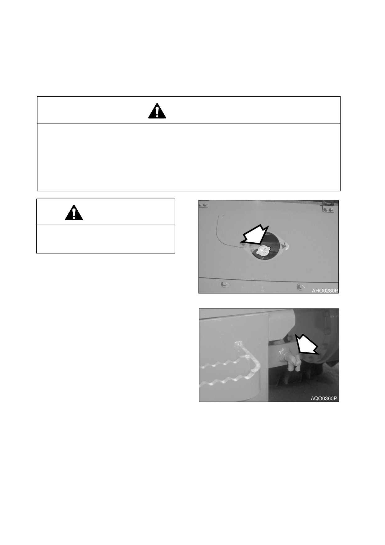
Figure 68
1.
Slowly open the radiator cap (Figure 68) to
allow any pressure to escape.
NOTE: Do not remove the coolant filter.
2.
Place a container under the radiator and
open the drain valve (Figure 69).
Figure 69
022-00029AE Operation and Maintenance Manual
Inspection, Maintenance and Adjustment 4-37
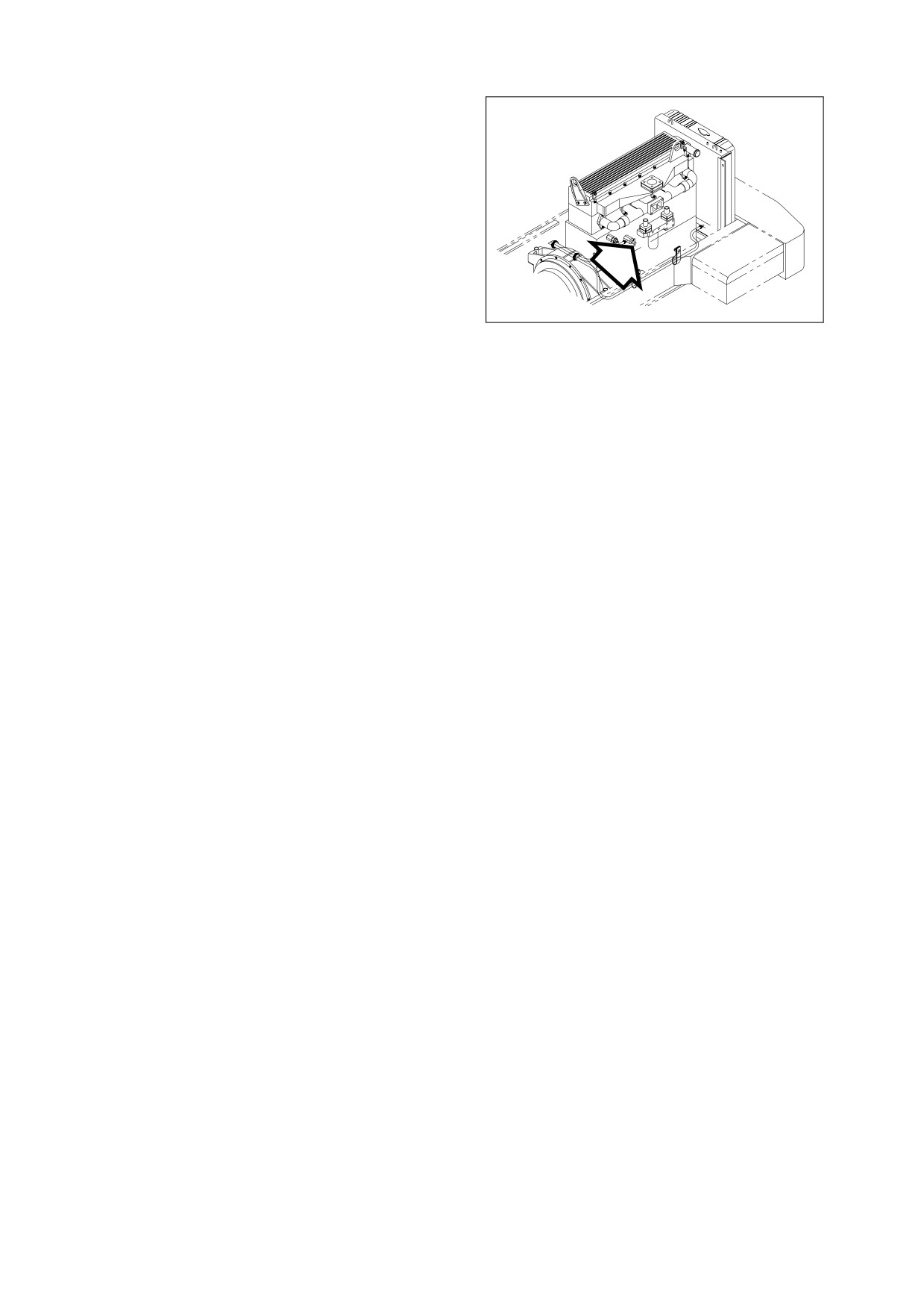
3.
Open heater shutoff valve (Figure 70) to
allow coolant to drain from heater core.
4.
Install drain plug, and close vent and drain
valve after coolant has completely drained
from system.
5.
Fill cooling system with a flushing solution.
NOTE: When filling engine with
flushing solution open vent
(Figure
68) on intercooler to
allow air to escape. Close vent
when coolant is present.
AQO0370L
Figure 70
6.
Run engine at low idle until the coolant
temperature gauge reaches the "GREEN
ZONE." Run engine for another 10 minutes.
7.
Alter allowing engine to cool.
8.
Drain flushing fluid and fill system with water.
9.
Run engine again to allow water to completely circulate.
10.
Drain water and fill system with proper anti-freeze mixture for ambient temperature. Refer to coolant
concentration table (See page 4-14)
NOTE: When filling engine with coolant, open vent (Figure 68) on intercooler to allow air to
escape. Close vent when coolant is present.
11.
Run engine without radiator cap installed, so that all air will be purged from system. Fill radiator to fill
neck.
12.
Drain and fill radiator coolant recovery tank.
DRAIN AND REPLACE TRANSMISSION OIL AND FILTER
NOTE: Transmission oil and filter must be changed after first 250 hours of operation to comply
with new machine break-in requirements. After first change, oil and filter must be changed
every 1000 hours. Follow procedure under 1000 hour maintenance interval (See page
4-24).
1.
Start machine and drive it until transmission fluid has warmed to 65 - 93°C (149 - 200°F). Park
machine on a level area.
2.
Place transmission lever in "NEUTRAL." Apply parking brake. Turn "OFF" engine. Block tires.
NOTE: See “Fluid Capacities” on page 4-5 for capacity.
4-38 Inspection, Maintenance and Adjustment
022-00029AE Operation and Maintenance Manual
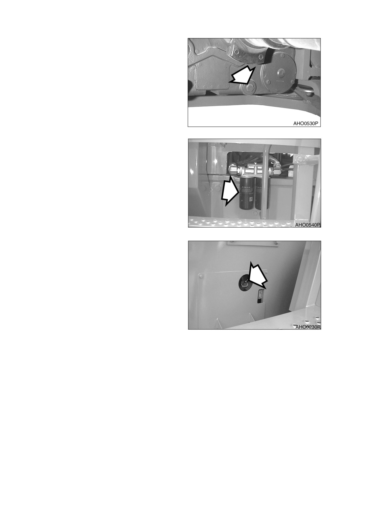
3.
Remove drain plug. Allow all transmission
fluid to drain into a receptacle. Properly
dispose of drained fluid. Clean drain plug.
4.
Install drain plug in transmission.
5.
Remove inlet strainer.
Use a
nonflammable, non-toxic solvent to clean
strainer.
6.
Inspect gasket on inlet strainer. Replace
gasket if it is damaged. Install inlet strainer.
7.
Remove breather filter. Clean breather
filter and install it.
Figure 71
8.
Rotate filter counterclockwise to remove it.
9.
Clean filter head.
10. Grease filter gasket and gasket mating
surface on filter head.
11. Thread filter onto filter head. Tighten filter
1/2 turn after filter gasket contacts filter
head. Filter should be torqued to 1.6 to 2.1
kg m (11.5 to 15 ft lb).
Figure 72
12. Fill transmission with fluid through fluid
supply pipe. Add fluid until fluid level
reaches low mark on dipstick.
13. Start engine. Idle engine for two minutes.
14. With engine idling, check transmission
fluid level. Add fluid until level reaches high
mark on dipstick.
15. Idle engine until transmission fluid
temperature reaches 82 - 93°C (180 -
200°F). Check fluid level with engine idling.
Level must reach high mark on dipstick.
Figure 73
16. Check filter for leaks while engine is
running.
022-00029AE Operation and Maintenance Manual
Inspection, Maintenance and Adjustment 4-39
CLEAN FUEL TANK AND STRAINER
WARNING!
Escaping fuel flammable and harmful to skin.
•
Do not smoke while draining moisture and sediment from tank.
•
Do not drain with engine running.
•
Do not allow fuel to remain on skin for an extended period of time.Wash thoroughly
with soap and water.
NOTE: It is easiest to clean the fuel tank when the fuel is almost empty.
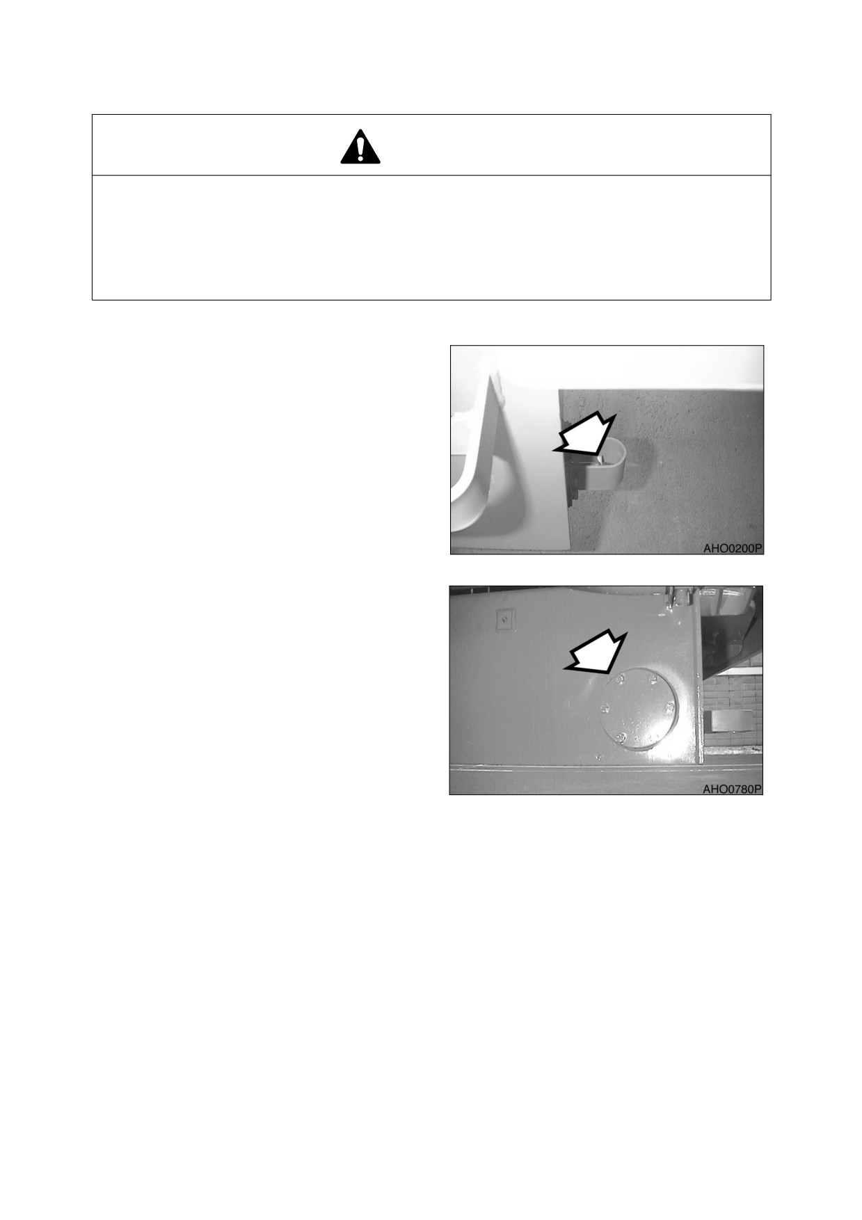
1.
Park the machine on a level surface, apply
the parking brake, lower the attachment to
the ground, and stop the engine.
2.
Open the drain cock (Figure 15) on the
bottom of the fuel tank.
3.
Drain the remaining fuel into a suitable
container.
Figure 74
4.
Remove the nuts with a 17mm wrench to
remove the inspection cover (Figure 75).
5.
Clean inside of the tank and suction
stainer.
6.
Install the inspection cover with a new
gasket. Tighten the nuts. Do not
overtighten.
7.
Close the drain cock.
8.
Fill the fuel tank.
9.
Check for any leaks at cover and plug.
Figure 75
4-40 Inspection, Maintenance and Adjustment
022-00029AE Operation and Maintenance Manual
CHECK AIR CONDITION REFRIGERANT
WARNING!
Mixing of tobacco smoke and freon is deadly.
Do not smoke while servicing or recharging air conditioning system.
1.
Apply the parking brake and lower the attachment to the ground.
2.
Remove the cover.
3.
Press the "HI" flow control switch to set maximum air flow.
4.
Set the temp. control switch fully to the cool position and fully open the cab doors.
5.
Slightly accelerate the engine to about the middle speed range (compressor speed 1500-1800 rpm.)
6.
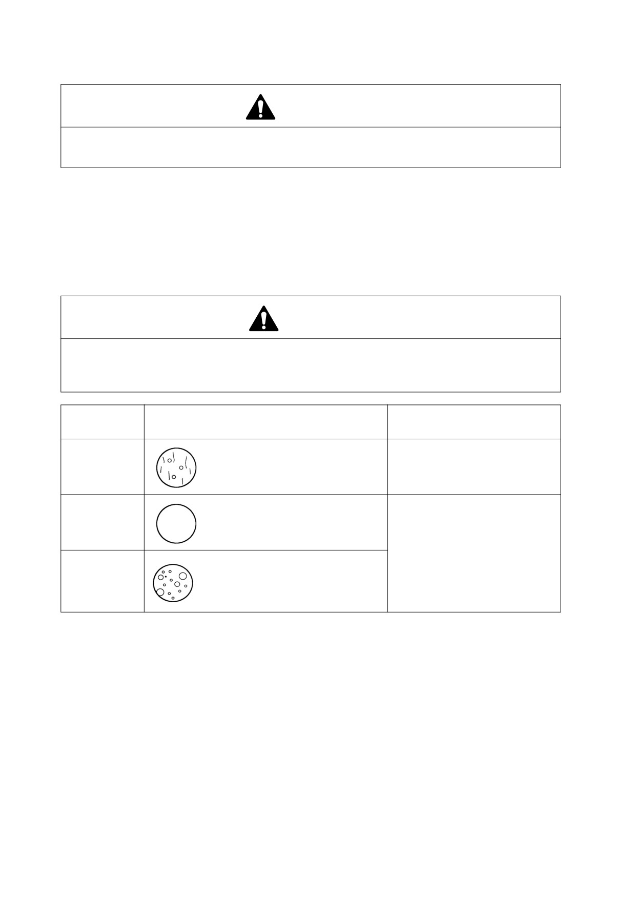
Compare the flow of bubbles in the sight glass with the drawings in the following table.
CAUTION!
Overfill refrigerant may cause dangerous high pressure and poor cooling action; and low
refrigerant level may cause compressor damage.
Always maintain refrigerant in normal level.
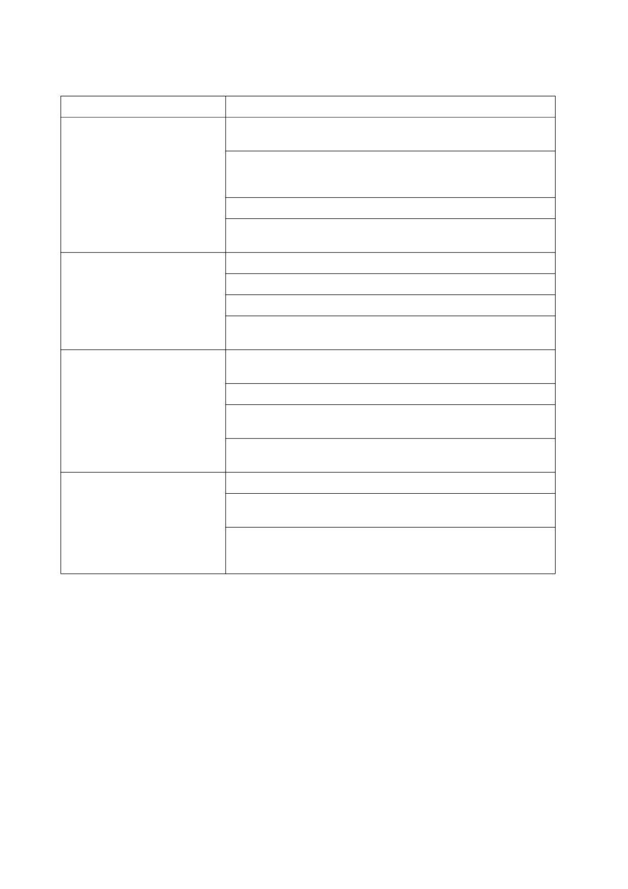
Amount of
Appearance of the Sight Glass
Solutions
Refrigerant
Almost clear.
Normal
Any bubbles disappear if the engine
speed is increased to 1500 rpm
High
No bubble is seen
Contact your local loader dealer
for inspection and recharging
refrigerant.
Low
A flow of bubbles is visible
CHECK AND ADJUST ENGINE
Contact your nearest loader dealer or local Cummins
Engine dealer for checking and adjusting the following items:
•
Engine Compression Pressure
•
Injection Pressure
•
Injection Timing
022-00029AE Operation and Maintenance Manual
Inspection, Maintenance and Adjustment 4-41
1,500 HOUR / 9 MONTH SERVICE
PERFORM ALL 10, 50, 150, 250, AND 500 HOUR SERVICE CHECKS
REPLACE OUTER AND INNER AIR CLEANER ELEMENTS
CAUTION!
Never remove air cleaner element while engine is running. This will allow dirt to be sucked into
engine and cause serious engine damage. Always turn engine "OFF" before servicing air
cleaner.
1.
Replace inner element when outer element is replaced.
2.
After removing outer element, remove wing nut and inner element.
3.
Clean out inside of air cleaner housing. DO NOT use compressed air to blow out housing.
4.
Install new inner element, and secure it into position with wing nut. DO NOT clean and re-use inner
element.
5.
Install new outer element, and secure it into position with wing nut.
6.
Install air cleaner cover.
NOTE: Make sure that all gaskets on wing nuts and cover are properly installed and seated.
AXLE DIFFERENTIAL AND PLANETARIES OIL REPLACEMENT
NOTE: Oil in both front and rear axle must be replaced after first 250 hours of operation to comply
with new machine break-in requirements. After that, axle oil check should be done every
250 hours of operation and replacement should be done every 1500 hours.
Each axle contains a center differential, and a planetary in each end. The same oil lubricates center
differential and planetaries in axle ends, but oil flows very slowly between these points. When checked, oil
must be checked and refilled at all three places at the same time. To drain and replace oil in an axle,
perform the following steps:
1.
Drive machine onto a level surface.
Position wheels on axle being drained so
that axle end level plugs are in the lowest
position. Apply parking brake. Block
wheels.
2.
Clean area around level plugs on both
ends of axle. Remove plugs.
NOTE: See
“Fluid Capacities” on
page 4-5 for capacity.
Figure 76
4-42 Inspection, Maintenance and Adjustment
022-00029AE Operation and Maintenance Manual
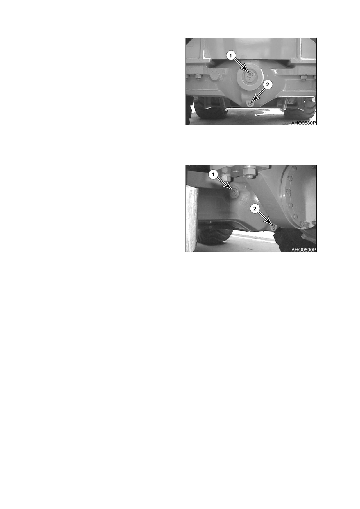
3.
Clean area around level plug (1, Figure
77) and drain plug
(2) on center
differential. Remove level plug
(1) and
drain plug
(2). Allow oil to drain into a
container.
4.
Install drain plug (2, Figure 77) into center
differential, and tighten.
5.
Pump oil into plug hole for level plug on
center differential. Add oil until oil level is
even with bottom of plug hole. Go to level
plug holes on axle ends. Add oil to these
openings until oil level is even with bottom
Figure 77 FRONT AXLE
of plug hole. Recheck level on center
differential. Add oil if necessary. When oil
level is satisfactory at all three level plug
holes, install and tighten level plugs at all three locations.
6.
Repeat procedure for other axle.
Figure 78 REAR AXLE
022-00029AE Operation and Maintenance Manual
Inspection, Maintenance and Adjustment 4-43

2,000 HOUR / ANNUAL SERVICE
PERFORM ALL 10 HOUR / DAILY, 50, 150, 250, 500 AND 1000 HOUR SERVICE CHECKS
REPLACE HOSES
1.
Replace hoses that carry brake fluid to wheel brakes. Also replace hoses that carry hydraulic fluid to
steering cylinders.
2.
It is difficult to determine condition of many hoses. The best way to ensure safe operation and to
maintain maximum performance is to replace hoses on a regular basis. If any brake or steering hoses
become damaged or appear defective in any way, replace them immediately despite time interval
since their last replacement.
BLEED BRAKES
When brake hoses or brake tubes are replaced, air can be introduced into brake hydraulic system. Air can
cause brakes to operate intermittently, which is a dangerous condition. Never operate machine with air in
brake hydraulic system. A spongy feel when pressing brake pedal is a sign that air is present in brake
hydraulic system.
To bleed air out of brake hydraulic system,
perform the following steps:
1.
Start engine and place transmission in
"NEUTRAL."
Figure 79
2.
Remove rubber cap from bleeder screw on
wheel.Place one end of a plastic hose (2,
1
Figure 80) over bleeder screw (1). Place
other end of hose in a container (3) filled
with brake fluid.
3.
Station one person in operator’s cab, and
2
one person at bleeder screw on wheel
being bled.
4.
Open bleeder screw (1, Figure 80). Then
press down on brake pedal until it rests on
3
floor of cab. Hold pedal down on floor of
cab. Close bleeder screw while pedal is
being held down. After bleeder screw has
HLB3018L
been closed, allow brake pedal to return to
Figure 80
upright position. Continue to open bleeder
screw and press down pedal as described
in this step, until fluid expelled from
bleeder hose has no air bubbles present.
4-44 Inspection, Maintenance and Adjustment
022-00029AE Operation and Maintenance Manual
5.
Securely close bleeder screw (1, Figure 80). Install rubber cap on bleeder screw.
6.
Perform bleeding procedure on other three wheels.
DRAIN AND REPLACE HYDRAULIC OIL
CAUTION!
Be certain that hydraulic oil has cooled before draining it. Hot oil could splash and cause burns.
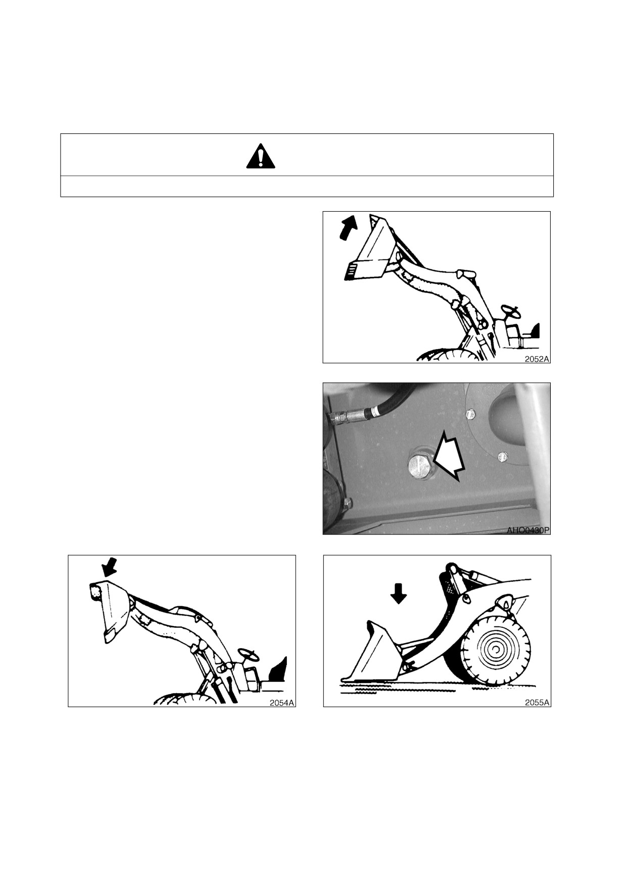
1.
Raise boom to its highest position. Tilt
bucket back as far as possible, and turn
"OFF" engine.
NOTE: See
“Fluid Capacities” on
page 4-5 for capacity.
Figure 81
2.
Position a catch tank beneath hydraulic
reservoir drain plug. Open reservoir
breather cap. (See Figure 10 on page 4-
10). Remove drain plug from bottom of
reservoir. (Figure 82). Allow all hydraulic
oil to drain out.
Figure 82
Figure 83
Figure 84
022-00029AE Operation and Maintenance Manual
Inspection, Maintenance and Adjustment 4-45
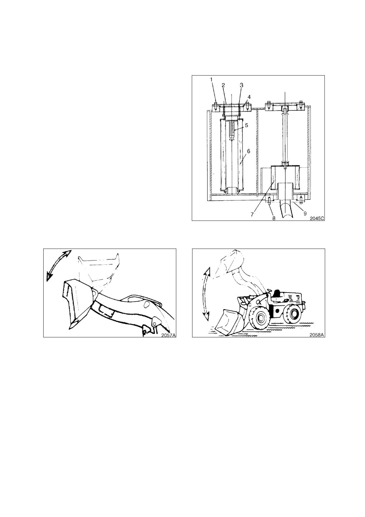
3.
Without starting engine, operate controls to dump bucket. (Figure 83). Then operate controls to lower
boom. (Figure 84). This will drain oil out of boom and bucket cylinders.
4.
Replace full flow hydraulic filters as described under “Loosen breather cap on hydraulic reservoir.
(See Figure 10 on page 4-10).” on page 4-27.
5.
Remove and clean pump inlet strainer
(Figure 85) inside hydraulic reservoir.
A. Remove bolts
(8, Figure
85) that
retain strainer cover (9).
B. Remove strainer cover (9, Figure 85)
and strainer (7) from reservoir.
C. Remove strainer (7, Figure 85) from
strainer cover.
D. Clean strainer
(7, Figure
85) in a
nonflammable, non toxic solvent.
E. Mount strainer
(7, Figure
85) on
strainer cover (9).
F.
Insert strainer
(7, Figure
85), and
cover (9), into reservoir.
G. Install and tighten bolts (8, Figure 85)
that retain cover (9).
6.
Install reservoir drain plug. Refill reservoir
Figure 85
by pouring oil in through breather cap
opening. Install and tighten breather cap.
Figure 86
Figure 87
7.
Start engine and operate controls to raise and lower bucket a few times. (Figure 86). Raise and lower
boom a few times. (Figure 87). Lower bucket to ground.
8.
Check reservoir sight gauge. (See Figure 9 on page 4-10). Oil level must be between upper limit and
lower limit on sight gauge. Remove breather cap and add oil if necessary.
4-46 Inspection, Maintenance and Adjustment
022-00029AE Operation and Maintenance Manual
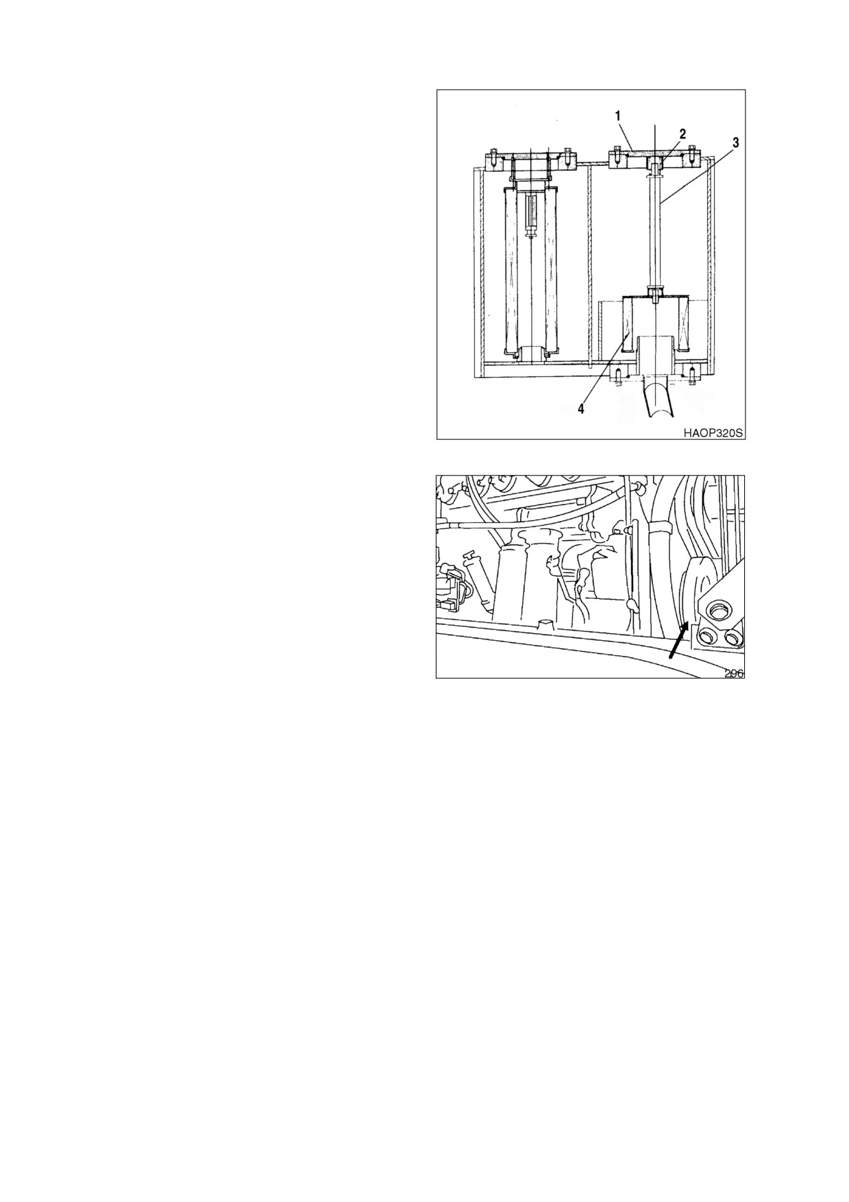
CLEAN HYDRAULIC OIL SUCTION
STRAINER
1.
Carefully remove bolts and cover
(1,
Figure 88) from top of hydraulic oil tank.
There is a spring (2) under the cover that
will force the cover up.
2.
Remove spring (2, Figure 88) and strainer
(4), by pulling on rod (3).
3.
Clean inside and outside of strainer.
Replace strainer if it is broken.
4.
Position strainer on boss portion of suction
pipe.
5.
Fill hydraulic oil tank. Check level using
sight gauge on side of tank.
6.
Place spring on rod and assemble cover.
Figure 88
CHECK VIBRATION DAMPER
1.
Park the machine on a level surface, apply
the parking brake, lower the attachment to
the ground, and stop the engine.
2.
Check the damper on the fan end of the
engine crankshaft.
3.
If dents, cracks, or any deformations are
found, contact your nearest loader dealer
for replacement.
Figure 89
022-00029AE Operation and Maintenance Manual
Inspection, Maintenance and Adjustment 4-47
CHECK BRAKE ACCUMULATOR
Test the brake accumulator for proper precharge of Nitrogen gas
WARNING!
Pressurized Nitrogen gas in brake accumulator may explode causing serious injury or death.
Never service brake accumulator unless trained properly.
1.
Park the machine on a level surface, apply the parking brake and lower the attachment to the ground.
2.
Run the engine at low idle for five minutes to fill the brake accumulator with oil.
3.
Stop the engine.
4.
Turn the key to the "ON" position.
5.
Count the number of times you can depress the right hand brake pedal before the brake warning light
comes on.
6.
If the number counted is less than five (5) there is some problem with the accumulator. Contact your
nearest loader dealer.
CHECK STEERING, BRAKE, DRIVE SHAFT, ENGINE, AND FUEL SYSTEM
4-48 Inspection, Maintenance and Adjustment
022-00029AE Operation and Maintenance Manual
SEVERE CONDITIONS MAINTENANCE
OPERATING CONDITION
REQUIRED MAINTENANCE
Mud, Water, Rain
1.
Check for loose fittings, obvious damage to machine, or any
fluid leakage.
2.
After completing operations, clean mud, rocks, or debris from
machine. Inspect for damage, cracked welds, or loosened
parts.
3.
Perform all daily lubrication and service.
4.
If machine was working in salt water or other corrosive
materials, be sure to flush equipment with fresh water.
Extremely Dusty
Or
Hot
1.
Clean engine air filter on a more frequent basis.
Environment
2.
Clean radiator and oil cooler fins to remove dirt and dust.
3.
Clean fuel system intake strainer and fuel filter more frequently.
4.
Inspect starter motor and alternator, and clean as often as
necessary.
Rocky Terrain
1.
Check wheels, tires, rims, and valve stems for damage or
excessive wear.
2.
Inspect for loose or damaged fittings and bolts.
3.
On a more frequent basis, inspect bucket and boom for
damage or excessive wear.
4.
Install a top guard and front guard as necessary for protection
against falling rock.
Extreme Cold
1.
Use proper grade of fuel for cold temperatures.
2.
Use a gauge to check antifreeze to be sure that it will provide
protection for coldest temperature expected.
3.
Use a hydrometer to check condition of batteries. In extremely
cold weather, remove batteries at night and store them in a
warm area.
022-00029AE Operation and Maintenance Manual
Inspection, Maintenance and Adjustment 4-49
FUEL TRANSFER PUMP
WARNING!
1.
Do not dry operate fuel pump for more than 15 seconds.
•
Cooling and lubrication of pump is achieved by fuel passing through the pump. If the
pump is dry operated, the heat generated by the moving parts will cause damage to
the pump rotors, vanes and seals. To prevent unnecessary wear and / or damage to
the pump do not dry operate the fuel pump for more than 15 seconds.
2.
Do not operate the pump for more than 15 minutes at a time.
•
Continuous usage of pump over the recommended time interval will cause
overheating of motor result in causing motor damage.
3.
Do not use refueling pump for other types of fuel. (Use only for diesel fuel.)
•
Do not use refueling pump for other types of fuel which have a low flash point.
•
Do not use refueling pump for fuel contaminated with water or high humidity. Moisture
in pump mechanism can cause rust and can create pump failure.
4.
Always operate pump using the strainer installed on the inlet hose. This will prevent any
foreign materials from being introduced into the pump. Always maintain the pump and all of
its components in a clean condition.
•
If dirt or other foreign materials enter the pump, it can become lodged between the
rotor and / or vanes and generate heat which can cause pump damage.
•
Do not remove strainer or use a strainer with larger mesh to increase the flow of fuel.
5.
Be careful not to overfill or spill fuel.
6.
Make sure the direction of check valve is in line with the flow direction of fuel.
7.
If any parts or components of the pump become lost, damaged or inoperable, immediately
replace it with a new one.
IMPORTANT
If there are any sign of leakage while operating transfer pump, inspect the following components
to prevent any fires or hazardous fuel spills.
•
Check all hoses leading to and from the transfer pump.
•
Check all hose clamps.
•
Check transfer pump inlet port.
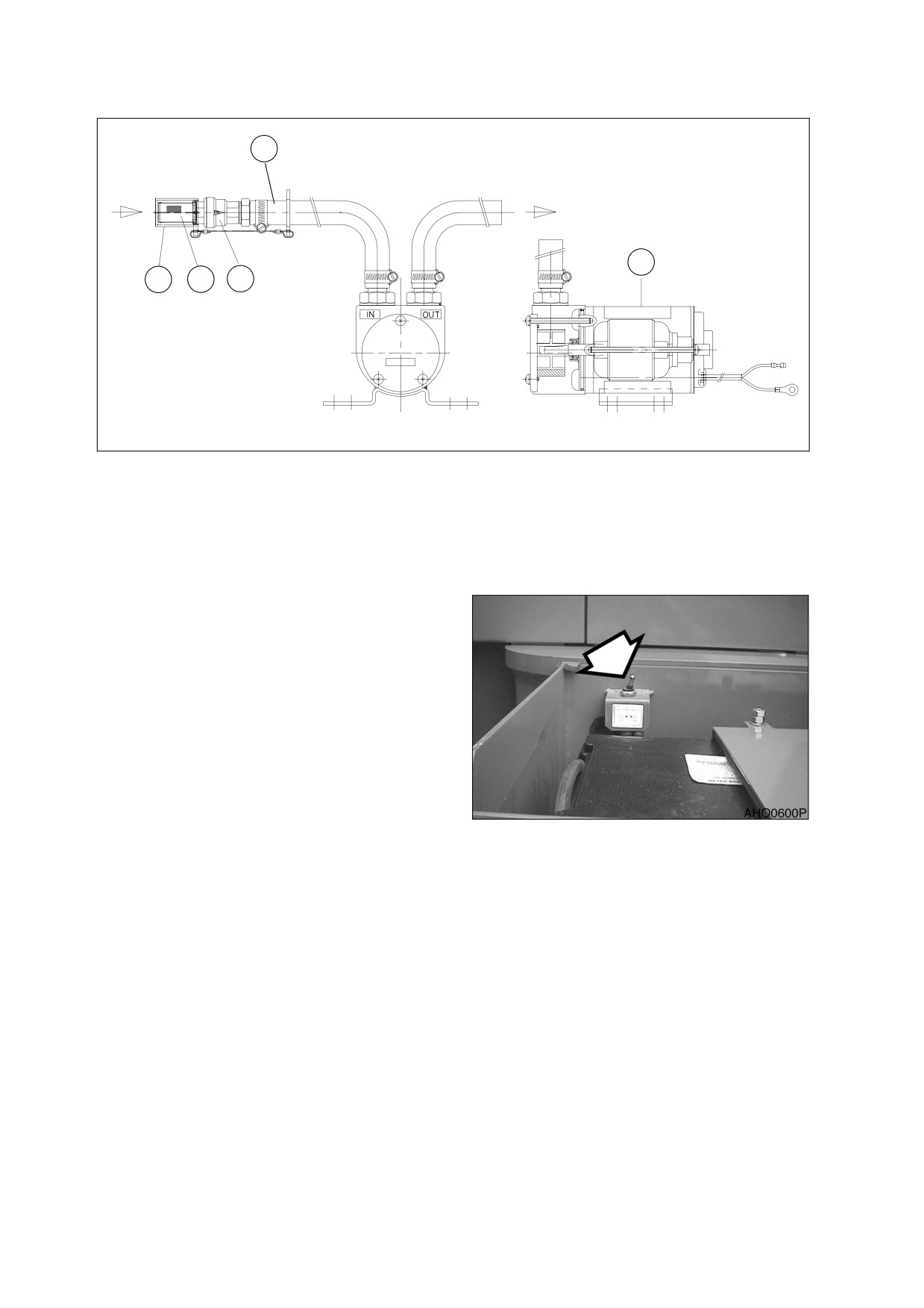
This transfer pump is used to transfer fuel from a refueling source to fuel tank. A check valve is installed in
the inlet hose to prevent fuel from flowing backward from fuel tank to source. A strainer is installed in inlet
hose to prevent any foreign material from being introduced into transfer pump or fuel tank.
A thermal limiter, built into motor, will automatically shut off the circuit if motor is overheating to protect
motor from damage.
4-50 Inspection, Maintenance and Adjustment
022-00029AE Operation and Maintenance Manual
5
1
4
3
2
HAOP401L
Figure 90
1.
Remove strainer cap (4, Figure 90) from inlet hose.
NOTE: Keep strainer cap in a safe location to reseal strainer after refueling is complete.
2.
Insert inlet hose (5, Figure 90) into refueling tank.
3.
Turn fuel pump switch to “ON” position.
NOTE: The transfer pump rate of flow
is approximately
20 liters
/
minute. Use extra care not to
over fill fuel tank so that fuel
does not over flow.
4.
Once fuel transfer is completed,
immediately turn switch to “OFF” position
to stop pump.
5.
Lift inlet hose from fueling source and turn
switch to “ON” position for 2~3 seconds to
drain remaining fuel from hose to fuel tank.
Figure 91
6.
Replace strainer cap (4) to inlet strainer
and return hose to storage position.
022-00029AE Operation and Maintenance Manual
Inspection, Maintenance and Adjustment 4-51
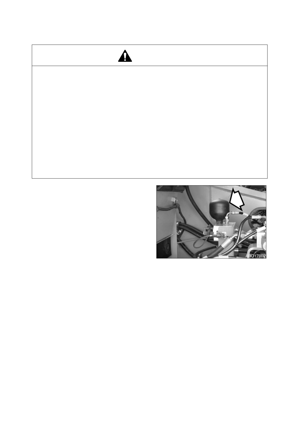
HANDLING OF ACCUMULATOR
WARNING!
Even though the engine is stopped, the hydraulic accumulators for the pilot system are still
charged. Do not disconnect any pilot system hoses until accumulator pressure has been
released from the circuit. To release pressure, turn the starter switch to “I” (ON) position and
operate pilot control valve lever and brake pedal. Even though the engine is shutdown hydraulic
actuated components may move while releasing pilot pressure. Keep all personnel away from
machine while performing this operation.
•
Set pilot cutoff switch to "O" (OFF) position after stopping engine.
•
DO NOT mishandle accumulator(s). They are very dangerous because they contain
high pressure nitrogen gas.
•
DO NOT punch a hole or apply heat or fire to an accumulator.
•
DO NOT weld on accumulator, or try attaching anything to it.
•
When replacing an accumulator, contact a DOOSAN distributor or sales agency so the
gas can be properly released.
•
Wear safety goggles and protective gloves when working on an accumulator.
Hydraulic oil under pressure can penetrate the skin and cause serious injuries.
Release pilot accumulator pressure using the
following procedure;
1.
Lower front attachment
(bucket) on the
ground.
2.
Stop the engine.
3.
Set pilot cutoff switch on "I" (ON) position.
4.
Turn starter switch "ON."
5.
Fully move pilot control valve lever in all
directions.
6.
Repeatedly press brake until brake oil
Figure 92
pressure warning light turns "ON." Press
the pedal another eight to nine times.
7.
Set pilot cutoff switch on "O"
(OFF)
position.
8.
Remove accumulator by unscrewing it
slowly.
4-52 Inspection, Maintenance and Adjustment
022-00029AE Operation and Maintenance Manual
CHECK HYDRAULIC PRESSURES
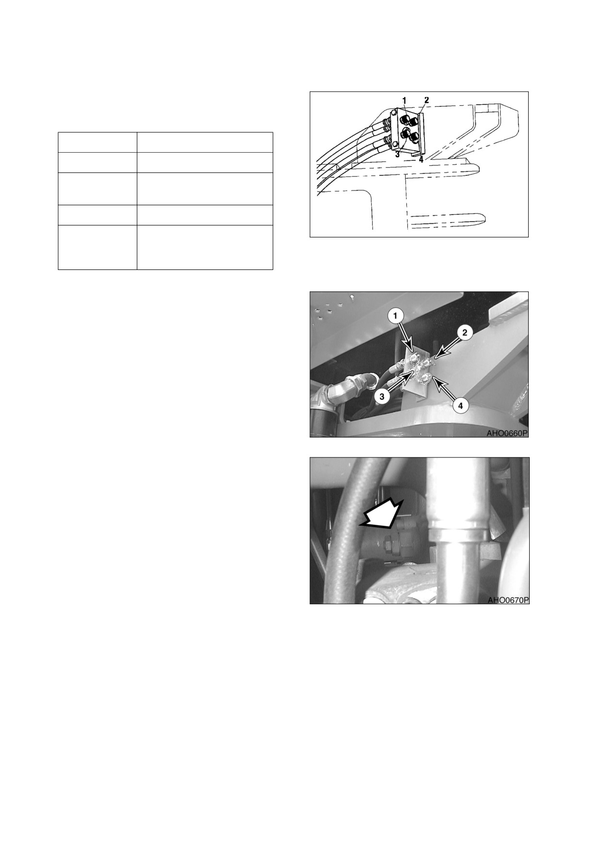
Hydraulic pressures for most systems can be
check by using the remote test ports shown in
Figure 93.
Port Number
Description
1
Main Pump Pressure
2
Transmission System
Pressure
3
Brake Charge Pressure
HAOP341S
4
Pilot Control Valve Lever
Figure 93
(Joystick) Activation
Pressure
MAIN PUMP PRESSURE
1.
Attach gauge to (Port 1, Figure 94)
2.
Relief cartridge for main pump must open
at 200+5 kg/cm2 (2,918+70 psi).
Figure 94
3.
Adjust screw on relief valve cartridge (1,
Figure 95). Loosen lock nut and turn screw
clockwise to raise relief pressure. Turn
screw counterclockwise to lower relief
pressure.
Tighten lock nut after pressure has been
adjusted.
Figure 95
022-00029AE Operation and Maintenance Manual
Inspection, Maintenance and Adjustment 4-53
TRANSMISSION SYSTEM PRESSURE
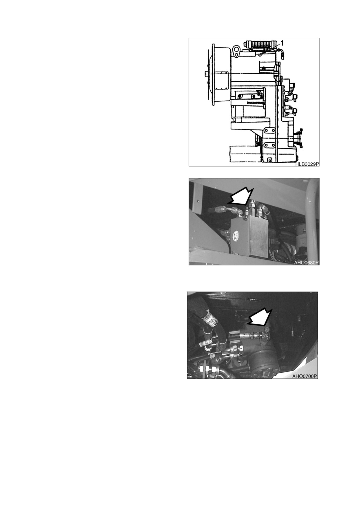
1.
Attach gauge to (Port 2, Figure 93)
2.
Pressure 16-18 kg/cm2 (228-256 psi)
BRAKE CHARGE PRESSURE
1.
Attach gauge to (Port 3, Figure 93).
2.
Relief pressure for unloading is 140 kg/
cm2 (1,991 psi). Relief pressure for loading
is 120 kg/cm2 (1,707 psi).
Figure 96
PILOT CONTROL VALVE LEVER (JOYSTICK)
ACTIVATION PRESSURE
1.
Attach gauge to (Port 4, Figure 94).
2.
Adjust relief cartridge (Figure 97) on pilot
parking valve. Relief pressure should be
+3
+43
set at 37
-2
kg/cm2 (526
-28
psi).
3.
Loosen lock nut on adjusting screw. Turn
adjusting screw clockwise to raise relief
pressure.
Turn
adjusting
screw
counterclockwise to lower relief pressure.
4.
Tighten lock nut after adjustment has been
Figure 97
made.
STEERING PUMP PRESSURE
1.
Attach gauge to steering valve port,
(Figure 94).
Figure 98
4-54 Inspection, Maintenance and Adjustment
022-00029AE Operation and Maintenance Manual
2.
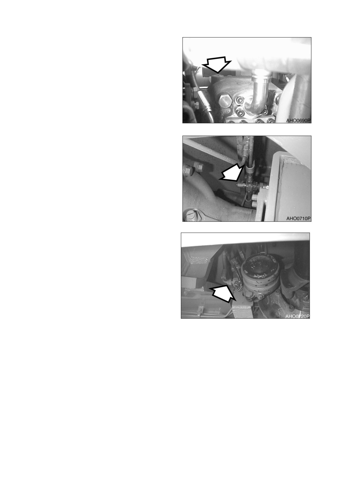
Adjust relief valve cartridge on amplifier
(Figure 99). Cartridge must be adjusted to
open at 185 ±5 kg/cm2 (2,630 ±70 psi).
3.
Unscrew remove plug and washer. Adjust
screw that is beneath plug. Turn screw
clockwise to raise relief pressure. Turn
screw counterclockwise to lower relief
pressure. One turn varies 65kg/cm2.
4.
Install plug and washer after pressure has
been adjusted.
Figure 99
SERVICE BRAKE OUTLET PRESSURE
1.
Attach gauge to brake pressure test
(Figure 100) port of front axle.
2.
Outlet pressure should be 60 kg/cm2 (853
psi).
Figure 100
PARKING BRAKE RELEASE PRESSURE
1.
Attach a pressure gauge to parking brake
port (Figure 101).
2.
Parking brake pressure should be 88 kg/
cm2.
Figure 101
022-00029AE Operation and Maintenance Manual
Inspection, Maintenance and Adjustment 4-55
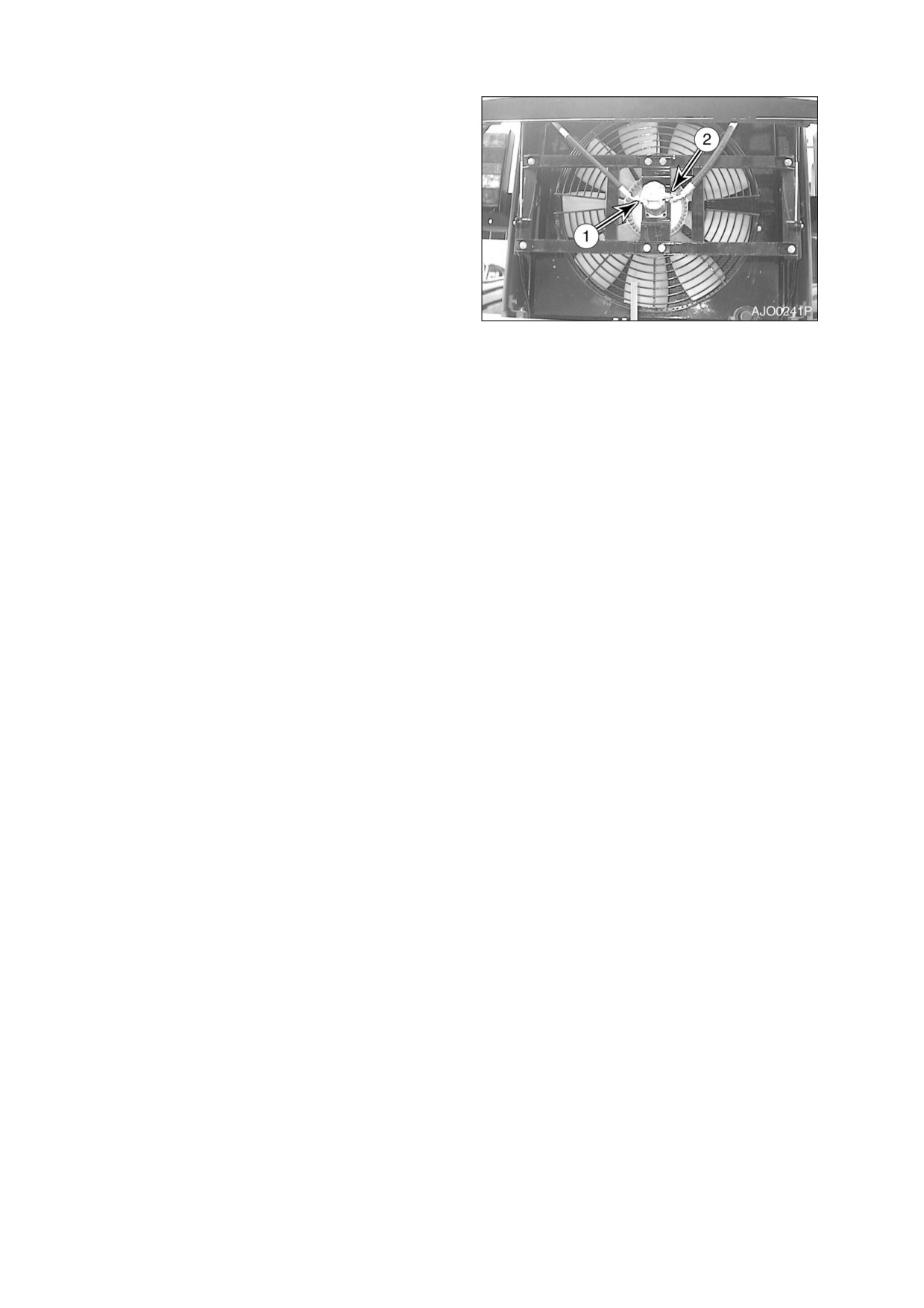
FAN MOTOR PRESSURE
1.
Attach gauge to inlet port of fan motor
(1,Figure 102).
2.
Adjust screw on relief valve cartridge
(2,Figure 102). Pressure should be 95 kg/
cm2 (1,350 psi).
3.
Loosen lock nut on adjusting screw. Turn
adjusting screw clockwise to raise relief
pressure.
Turn
adjusting
screw
counterclockwise to lower relief pressure.
4.
Tighten lock nut after adjustment has been
Figure 102
made.
4-56 Inspection, Maintenance and Adjustment
022-00029AE Operation and Maintenance Manual
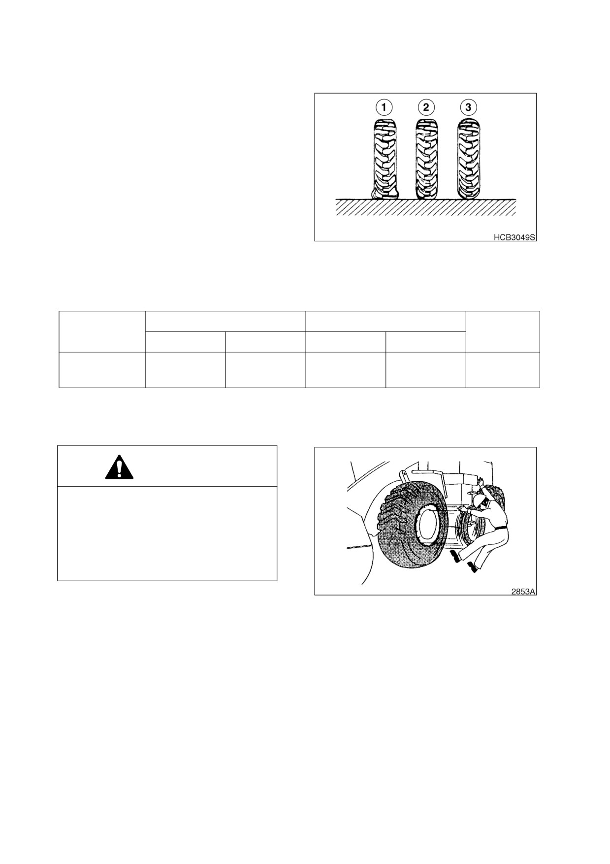
TIRES AND WHEELS
Properly inflated tire
(2, Figure
103) is an
important factor in determining tire performance
and tire life. A tire that is under-inflated
(1,
Figure 103) does not properly support machine,
and will wear out quickly. Over-inflated tires (3,
Figure 103) have poor traction and puncture
easily.
Use a pressure gauge to measure tire pressure.
Always measure tire pressure before machine
has been working, when tires are cold. Use
table below to determine correct pressure for
front or rear tires when driving machine, or when
working machine.
Figure 103 BIAS PLY TIRES ONLY
Check tires for damage and embedded objects.
Check valve stems for damage.
Working Pressure
Driving Pressure
Tire Dimension
Remarks
Front Tire
Rear Tire
Front Tire
Rear Tire
29.5-25-22PR
Bias Ply Tire
3.5 kg/cm2
3.3 kg/cm2
2.8 kg/cm2
2.0 kg/cm2
(Standard)
(50 psi)
(47 psi)
(40 psi)
(29 psi)
WHEEL NUT TORQUE
Tighten wheel nuts to 85 kg•m (615 ft lb).
WARNING!
If a wheel and tire must be removed from
machine and replaced, or if a tire must be
replaced on wheel, allow this task to be
performed only by experienced service
personnel. A tire rim could be propelled
off wheel and cause serious bodily injury
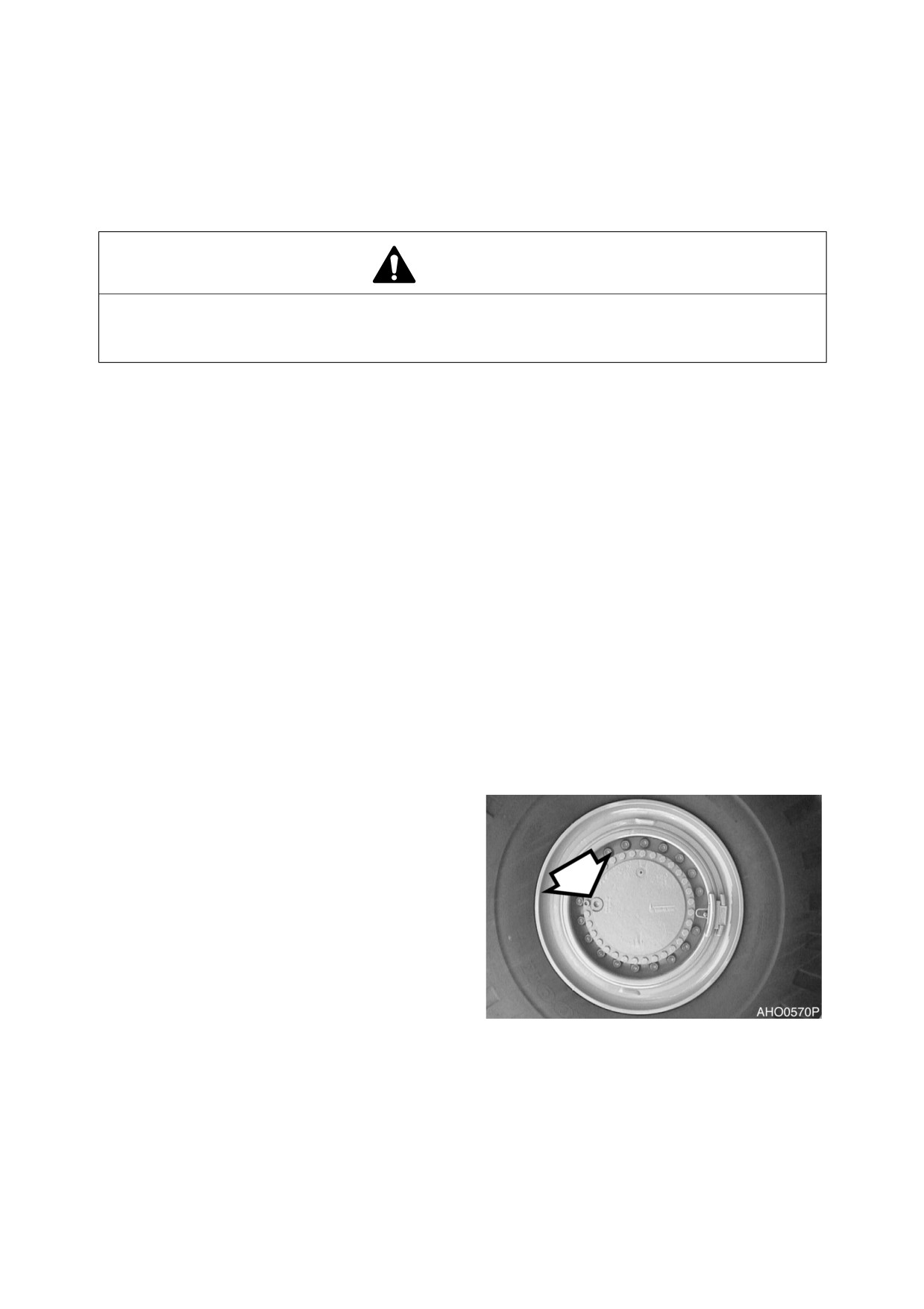
or death. See Figure 104.
Figure 104
022-00029AE Operation and Maintenance Manual
Inspection, Maintenance and Adjustment 4-57
CHECK TIRE FOR DAMAGE
WARNING!
Improper servicing or changing tires and rims can cause explosion resulting in serious injury or
death.
Do not service or change tires and rims unless properly trained and equipped.
Contact your nearest loader dealer or tire manufacturer’s local dealer for tire servicing or
changing.
WARNING!
Overheated tire may explode causing serious injury or death.
If overheated tire is suspected, do not approach tire to distance of less than15m (50ft).
Stay away until tire and rim cool down.
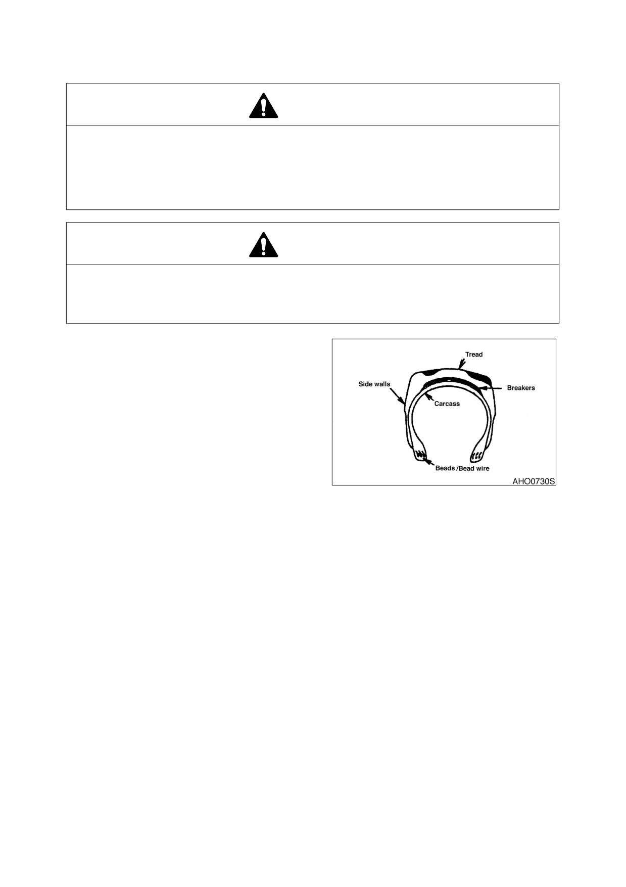
If the following defects are found in tires, for
safety reasons the tires should be replaced with
new tires.
For the replacement contact loader dealer or a
tire manufacturer’s local dealer.
•
Bead wire is broken or bent, or the
tire is greatly deformed.
•
Wear is excessive and the carcass
ply (including breaker) is exposed for
more than 1/4 of the circumference.
•
Damage to the carcass exceeds 1/3
Figure 105
of the tire width.
•
Tire layers are separated.
•
Radial cracks reach the carcass.
•
Deformation or damage which makes
the tire unsuitable for use.
4-58 Inspection, Maintenance and Adjustment
022-00029AE Operation and Maintenance Manual
ELECTRICAL SYSTEM
CHECK BATTERY CONDITION
WARNING!
Before starting any battery service work, make sure to shut the engine off and turn the starter
key to the "OFF" position.
The batteries create hydrogen gas. An explosion hazard exists, particularly with a deeply
discharged battery. Make sure that open flames, burning objects or sparks are kept away from
the battery compartment.
Battery electrolyte is diluted sulfuric acid. Take extreme caution when handling the batteries.
The electrolyte can cause severe chemical burns. If any electrolyte gets on your clothing or skin,
wash it off immediately with large quantities of water. If the electrolyte gets into your eyes, flush
them immediately with a large quantity of water and contact a doctor at once.
When installing a battery, wear safety glasses at all times.
When removing a battery, remove the Negative (-) or ground terminal first, and then the Positive
(+) terminal. This will prevent sparks or arcing that could cause an explosion. When installing a
battery, connect the Positive terminal first and then the Negative terminal. Make sure to fully
tighten the terminal clamps.
1.
In colder weather a greater drain is placed on the batteries when they are used for the preheat cycle
and when starting a cold engine. Battery performance decreases as the temperature gets lower.
2.
In extremely cold weather, remove the batteries at night and move them to a warm location. This will
help to keep them at a higher power level.
3.
Inspection of battery electrolyte level.
NOTE: The battery installed at the
factory is a Maintenance Free
(MF) type. Electrolyte under
normal conditions
should
remain at its proper level.
4.
Inspect charge condition of battery by
looking at the indicator light built into
battery.
•
GREEN: Normal.
HJB5002L
•
BLACK: Insufficient charging - check
Figure 106
alternator.
•
TRANSPARENT: Insufficient battery
fluid - replace with new battery.
NOTE: Colors may vary from one battery manufacturer to another. Always refer to instructions on
battery.
The batteries should always be replaced in pairs. Using an old battery with a new one will
shorten the life span of the new battery.
022-00029AE Operation and Maintenance Manual
Inspection, Maintenance and Adjustment 4-59
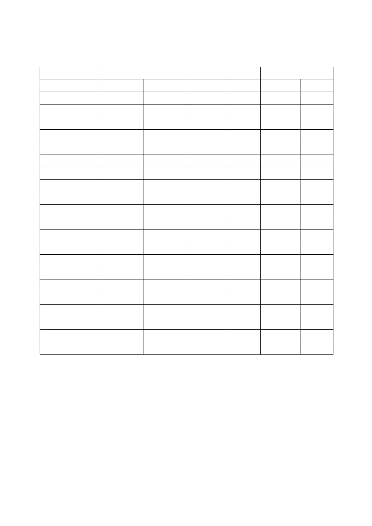
BOLT TORQUE CHART
Tightening Torque Specifications for Metric Bolts (For coated threads, pre-lubricated assemblies)
Grade
Gr. 8.8
Gr. 10.9
Gr. 12.9
Dia.
Kg•m
ft lb
Kg•m
ft lb
Kg•m
ft lb
5 mm x std
0.59
4.3
0.79
5.7
1.0
7.2
6 mm x std
1.00
7.3
1.38
10
1.66
12
8 mm x std
2.49
18
3.46
25
4.15
30
8 mm x 1.0
2.76
20
3.87
28
4.56
33
10 mm x std
4.84
35
6.92
50
8.30
60
10 mm x
1.0
4.84
35
7.05
51
8.30
60
12 mm x std
8.57
62
11.89
86
14.52
105
12 mm x
1.5
9.00
65
12.59
91
14.94
108
14 mm x std
13.55
98
18.95
137
23.10
167
14 mm x
1.5
14.94
108
21.02
152
24.89
180
16 mm x std
20.88
151
29.46
213
35.54
257
16 mm x
1.5
22.54
163
31.53
228
38.03
275
18 mm x std
28.90
209
40.52
293
48.41
350
18 mm x
1.5
32.50
235
45.92
332
55.04
398
20 mm x std
40.94
296
57.95
419
69.01
499
20 mm x
1.5
46.05
333
64.03
463
77.03
557
22 mm x std
54.90
397
77.86
563
93.08
673
22 mm x
1.5
61.00
441
86.02
622
105.00
759
24 mm x std
71.00
513
100.00
723
120.00
868
24 mm x
2.0
78.00
564
109.95
795
130.00
940
27 mm x
2.0
115.06
832
160.00
1157
195.00
1410
4-60 Inspection, Maintenance and Adjustment
022-00029AE Operation and Maintenance Manual
LONG TERM STORAGE
CLEANING
Pressure wash machine. Inspect machine for any damage or missing parts. Drive machine to check
steering linkage for damage.
HYDRAULIC SYSTEM
Start engine and allow it to idle for a few minutes. Drive machine around for 2 - 3 minutes. Raise and lower
boom 2 - 3 times. Crowd and dump bucket 2 - 3 times. This will circulate hydraulic fluid through all hydraulic
systems.
LUBRICATION
Perform all daily maintenance procedures listed in this section (Section 4.) Grease all grease fittings in
steering linkage. Apply a coating of light oil to all exposed cylinder rods. Apply a coating of light oil to all
control linkages and all control valve spools. Check condition of oil coating each month and add to coating
where necessary.
BATTERY
Disconnect cables from battery, or remove battery from machine. If battery is removed, fully charge battery
and store it.
COOLING SYSTEM CARE
If cooling system does not need antifreeze and is filled with water only, add an anti-rust additive. If
temperatures below freezing are expected, add antifreeze to protect system to level of cold expected. See
antifreeze protection Table 4-1. Use a hydrometer to check level of antifreeze protection once each month.
If desired, cooling system can be completely drained. If system is drained, place a sign in operator’s cab to
warn operator that there is no coolant in engine.
022-00029AE Operation and Maintenance Manual
Inspection, Maintenance and Adjustment 4-61
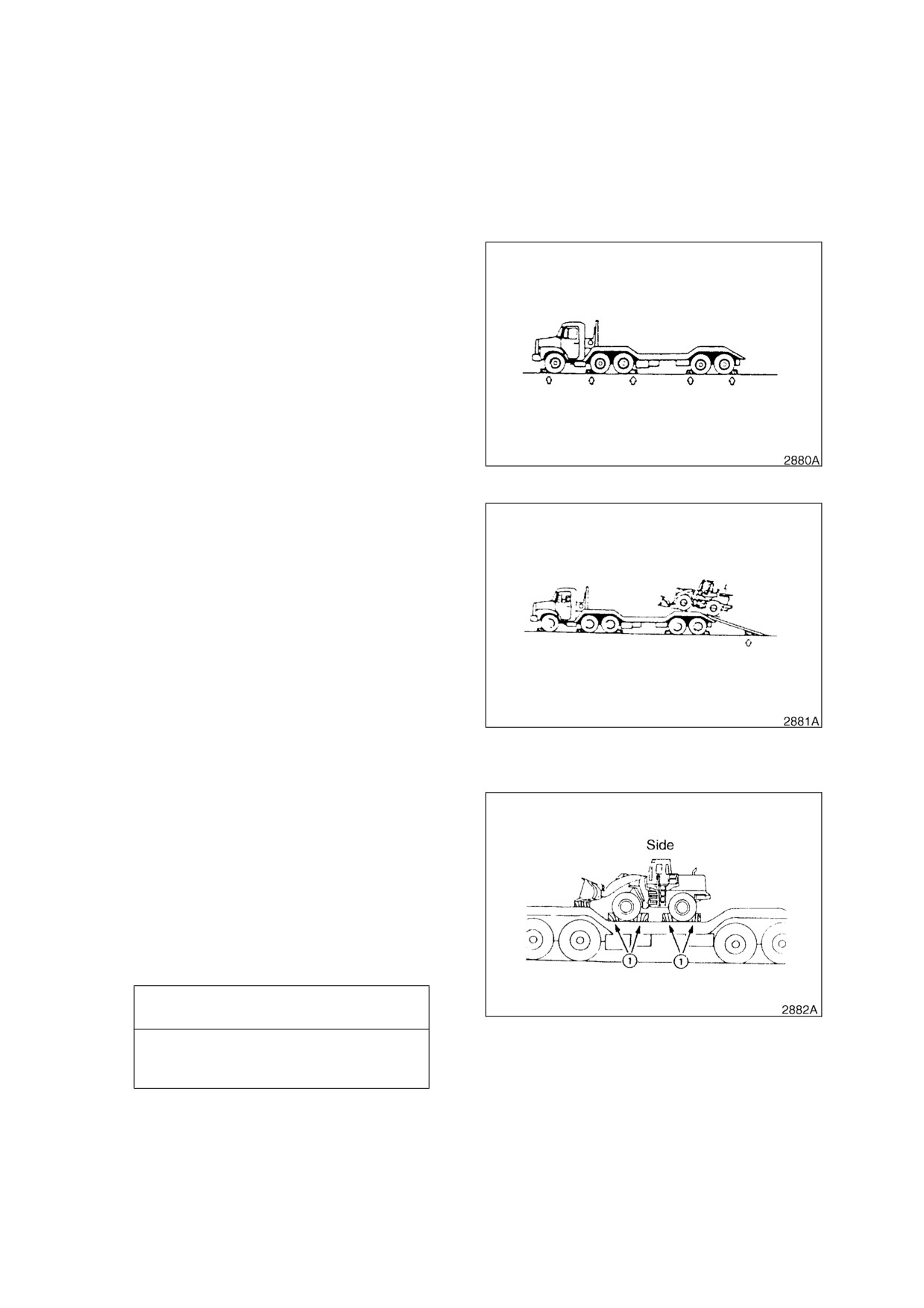
5TRANSPORTATION
LOADING MACHINE ON A TRAILER
When transporting the machine observe the
various road rules, road transportation vehicle
laws and vehicle limit ordinances, etc.
It is a good idea to obtain special platform for
loading and unloading the machine.
1.
Park the trailer on a flat firm roadbed. Keep
a fairly long distance between the road
shoulder and the machine.
2.
Properly apply the brakes of the trailer and
place wheel chocks in front of and behind
the tires to ensure that the trailer does not
move.
Figure 1
3.
Fix the ramp in line with the centers of the
trailer and the machine.
4.
Determine the position of the ramp, then
slowly load the machine onto to the
specified part of the trailer.
NOTE: Have someone in clear view
and in a safe position provide
directions while loading.
5.
Lower the bucket and lock control lever
using the pilot cutoff switch.
6.
Apply the parking brake and set the
Figure 2
articulation stopper in the "LOCKED"
position.
7.
Tape over the exhaust stack outlet to
prevent turbo "Wind-milling" damage
8.
Place blocks in front of and behind the
tires to prevent the machine from moving.
9.
Fasten the machine to the trailer with
chains or cables at lower part of the rear
chassis. Additional chains or cables may
be used but do not damage brake lines or
cylinder rods.
IMPORTANT
Figure 3
Brake pipe runs on axle housing.
Do not fasten axle housing.
022-00029AE Operation and Maintenance Manual
Transportation 5-1
10. Determine the route for transporting the machine by taking into account the width, height and weight
of the machine and the truck.
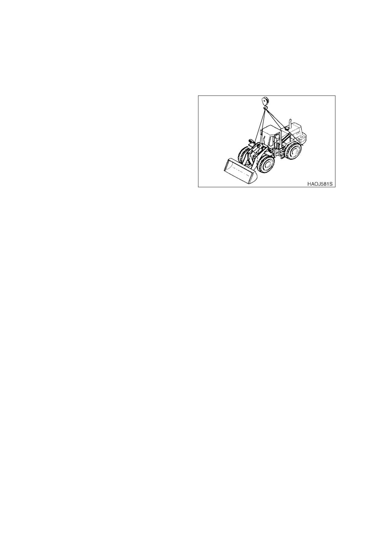
SUMMARY OF SAFETY PRECAUTIONS FOR LIFTING
To make safe lifts, the following items must be
evaluated by operator and work site crew.
•
Condition of ground support
•
Wheel loader configuration and
attachments
•
Weight, lifting height and lifting radius
•
Safe rigging of load
•
Proper handling of suspended load
Taglines on opposite sides of load can be very
helpful in keeping a suspended load secure, if
Figure 4
they are anchored safely to control points on
ground.
5-2 Transportation
022-00029AE Operation and Maintenance Manual
6TROUBLESHOOTING
ENGINE
Problem
Possible Causes
Remedies
Starter does not operate
Blown fuse
Replace fuse
Low battery power
Charge battery
Poor terminal contact
Clean and tighten connections
Starter switch failed
Replace switch
Starter relay failed
Replace relay
Starter control failed
Replace controller
Wiring harness faulty
Replace harness
Battery relay failed
Replace relay
Starter engages, engine
does
Blown fuse
Replace fuse
not start
Fuel gelled in cold weather
Replace fuel
Fuel filters plugged
Replace filters
Water or dirt in fuel system
Clean system and add new fuel
Air in fuel system
Purge air from system
Engine stop control failed
Replace stop control
Engine stop relay failed
Replace relay
Engine starts, runs only at low
Engine oil viscosity incorrect
Change oil
speed or shuts down
Clogged or dirty fuel injectors
Clean injectors
Fuel filters plugged
Replace filters
Engine stop motor cable out of
Readjust
adjustment
Engine speed control cable out
Readjust
of adjustment
Engine knocks, runs unevenly or
Low engine oil
Refill
surges
Plugged air intake system
Clean system and replace filter
Injection pump out of adjustment
Contact your DOOSAN dealer
Plugged fuel filter
Replace fuel filter
Water or dirt in fuel system
Clean system and add new fuel
Clogged or dirty fuel injectors
Clean injectors
022-00029AE Operation and Maintenance Manual
Troubleshooting 6-1
Problem
Possible Causes
Remedies
Engine has poor power
Plugged air intake system
Clean system and replace filter
Clogged or dirty fuel injectors
Clean injectors
Fuel filters plugged
Replace filters
Engine speed control cable out
Readjust
of adjustment
Injection pump out of adjustment
Contact your DOOSAN dealer
Valve backlash faulty
Adjust backlash
Engine runs hot
Low coolant level
Add coolant
Thermostat faulty
Replace thermostat
Radiator cap faulty
Replace radiator cap
Radiator core plugged
Clean radiator
Oil cooler core plugged
Clean oil cooler
Fan belt loose or damaged
Tighten or replace as required
Temperature sensor faulty
Replace sensor
Engine oil pressure warning light
Low engine oil level
Add oil
turns "ON," and buzzer sounds
Wrong grade oil for weather
change oil
conditions
Clogging oil filter element
Change filter and oil
Defective alarm switch
Oil leakage from pipe or joint
Contact your DOOSAN dealer
Clogging suction strainer
Excessive engine wear
Defective oil pump
Coolant temp, warning light
Low engine coolant level
Add coolant
turns "ON."
Loose/slipping/broken fan belt
Adjust or replace belt
Clogging radiator fins
Clean
Scale or mineral build up inside
Flush or professionally clean
radiator
Defective alarm switch (gauge is
in green)
Contact your DOOSAN dealer
Low water pump flow
Thermostat stuck or missing
6-2 Troubleshooting
022-00029AE Operation and Maintenance Manual
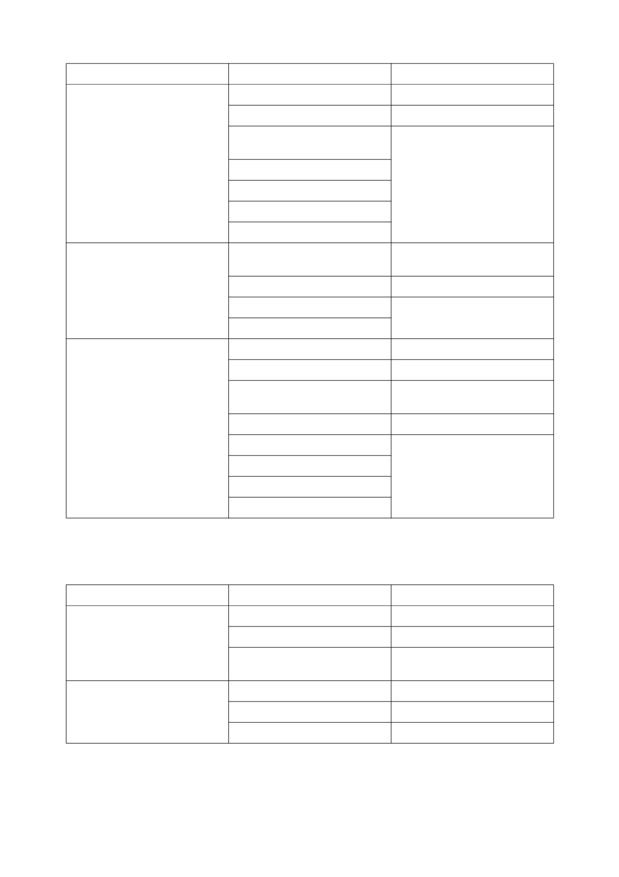
Problem
Possible Causes
Remedies
Engine does not start when the
Fuel filter element clogging
Replace fuel filter
starter motor is turning
Starter motor speed too low
Booster Battery may be used
(Also
see
ELECTRICAL
TROUBLESHOOTING)
Defective engine shut off
solenoid
Fuel pump failure
Contact your DOOSAN dealer
Incorrect fuel injection timing
Compression pressure too low
Defective injectors
Unstable (rough) idling
Air in fuel lines
Tighten fuel connections and
filter
Fuel filter element clogging
Replace fuel filter
Fuel pump failure
Contact your DOOSAN dealer
Incorrect fuel injection timing
Insufficient power
Air cleaner element clogging
Clean or replace element
Fuel filer element clogging
Replace fuel filter
Throttle linkage adjustment
Check and adjust linkage
wrong
Engine oil level too high
Check dipstick and correct level
Incorrect valve clearance
Piston ring wear
Contact your DOOSAN dealer
Defective injectors
Fuel pump failure
HYDRAULIC SYSTEM
Problem
Possible Causes
Remedies
None of the controls function
Hydraulic pump failed
Contact your DOOSAN dealer
(loud noise from pumps)
Low hydraulic oil level
Add hydraulic oil as required
Suction
line
plugged or
Clean or replace as required
damaged
None of the controls function (no
Pilot pump failure
Contact your DOOSAN dealer
noise from pumps)
Cutoff solenoid valve failed
Replace solenoid
Safety limit switch is "ON"
Adjust limit switch clearance
022-00029AE Operation and Maintenance Manual
Troubleshooting 6-3
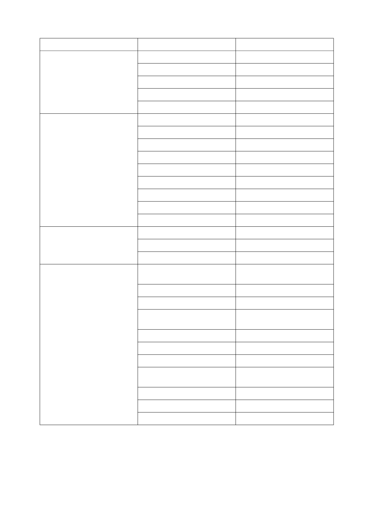
Problem
Possible Causes
Remedies
All actuators have low power
Low hydraulic oil level
Add hydraulic oil as required
Suction filter clogged
Clean filter
Hydraulic pumps faulty
Contact your DOOSAN dealer
Main relief pressure too low
Contact your DOOSAN dealer
Hydraulic pumps cavitating
Bleed air from hydraulic pumps
Only one or two actuators have
Overload relief pressure too low
Reset pressure
little or no power
Make-up check valve leaking
Clean or replace as required
Control valve spool faulty
Replace valve spool
Dirt in valve spool
Clean or replace as required
Actuator failed
Repair or replace as required
Cylinder seal failed
Repair or replace as required
Cylinder rod damaged
Repair or replace as required
Remote control valve failed
Replace control valve
Wrong pilot line connection
Reconnect pilot lines
Oil temperature too high
Debris in exterior of cooler
Clean exterior of cooler
Oil cooler faulty
Contact your DOOSAN dealer
Fan belt loose
Tighten fan belting as required
Actuators on one side of boom
Overload relief valve is not
Repair valve or replace
have little power or do not
operating properly
operate
Damaged hydraulic hose
Replace hose
Loose hydraulic fittings
Tighten fittings
Internal damage to control valve
Replace control valve
housing
Control valve spool damaged
Replace control valve
Sediment inside control valve
Clean and repair valve
Check valve internal leakage
Repair or replace valve
Damaged cylinder or pump
Repair or replace pump or
cylinder
Cylinder internal leakage
Repair or replace cylinder
Damaged cylinder rod
Replace rod
Pilot valve failure
Replace pilot valve
6-4 Troubleshooting
022-00029AE Operation and Maintenance Manual
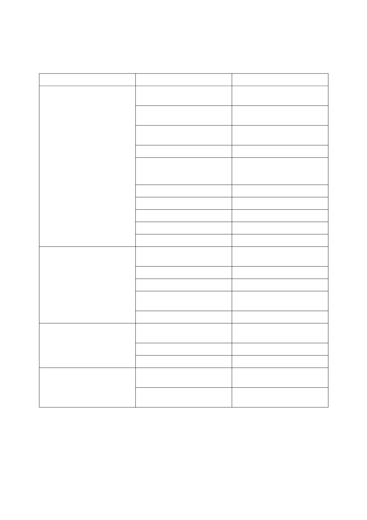
TRAVEL SYSTEM
GENERAL
Problem
Possible Causes
Remedies
Machine will not travel
Transmission clutch pressure
Adjust pressure
incorrect
Transmission charge pump
Replace pump
damaged
Damage to transmission control
Repair wiring
valve wiring harness
Burned travel relay or fuse
Replace relay or fuse
Forward/Reverse solenoid for
Clean and repair
transmission
control
valve
sticking
Damaged transmission clutch
Repair or replace clutch
Damaged drive shaft
Repair or replace
Damaged transmission or axle
Repair or replace
Wheel brakes not releasing
Repair brakes
Parking brake not releasing
Repair parking brake
Machine will travel but has little
Fluid
pressure
low
in
Repair clutch
power
transmission clutch
Transmission fluid low
Add fluid
Damage to torque converter
Repair or replace
Engine malfunction
See Engine Troubleshooting
Table
Brake valve
Disassemble and clean
Unusual transmission noise
Low transmission fluid, or low
Add fluid or change fluid
quality fluid
Worn transmission parts
Replace parts
Broken gears or bearings
Replace parts
Transmission fails to operate
Damaged transmission clutch
Replace discs
discs
Damaged wires in transmission
Repair wires
control wire harness
022-00029AE Operation and Maintenance Manual
Troubleshooting 6-5
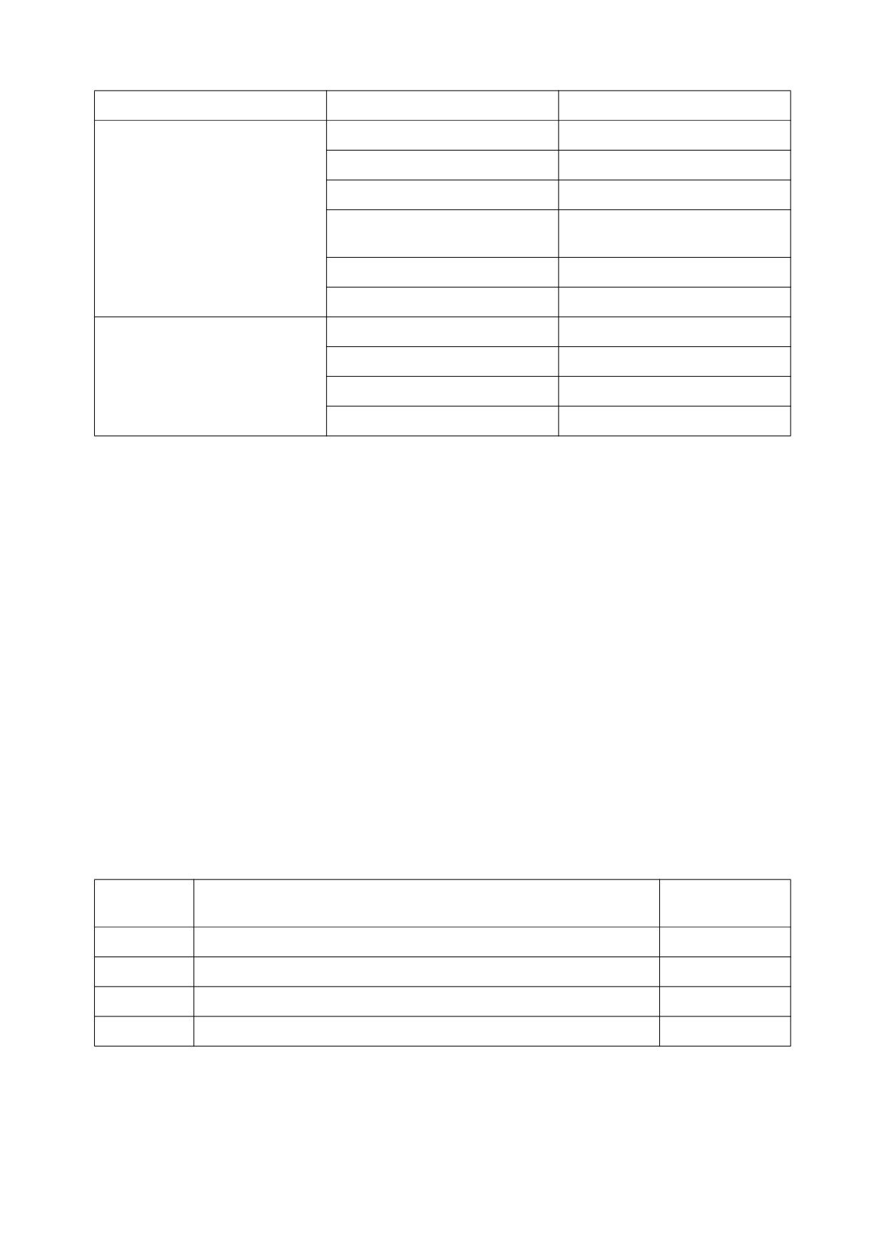
Problem
Possible Causes
Remedies
Drive shaft vibration Noisy
Bent drive shaft
Replace drive shaft
universal joints
Loose universal joints
Tighten bolts that secure joints
Worn or damaged universal joint
Replace universal joint
Loose universal joints
Tighten bolts that secure
universal joints
Lack of lubrication
Lubricate universal joints
Worn slip joint spline
Replace slip joint
Noisy Front or Rear Axle
Worn or broken gears
Replace gears
Low oil level, poor quality oil
Add oil, change oil
Worn bearings
Replace bearings
Worn shaft spline
Replace spline
TRANSMISSION ERROR CODES
The first number of the error code is the category that it is grouped into. They are as follows for the first
number:
1
Digital Input Signals
2
Analog Input Signals
3
Speed Signals
4
Speed Signals
7
Analog Current Output Signals
8
Analog Current Output Signals
9
Digital Output Signals
A Digital Output Signals
B Clutch Errors
D Power Supply
E High Speed Signals
F General Errors
Error Code
Meaning of Error Code
Remarks
Number
11
Logical error at gear range signal.
12
Logical error at direction select signal.
21
Short circuit to battery voltage at clutch cutoff input.
6-6 Troubleshooting
022-00029AE Operation and Maintenance Manual
Error Code
Meaning of Error Code
Remarks
Number
22
Short circuit to ground or open circuit at clutch cutoff input.
23
Short circuit to battery voltage at load sensor input.
Not used.
24
Short circuit to ground or open circuit at load sensor input.
Not used.
25
Short circuit to battery voltage or open circuit at temperature sensor
input.
26
Short circuit to ground at temperature sensor input.
31
Short circuit to battery voltage at engine speed input.
32
Short circuit to ground or open circuit at engine speed input.
33
Logical error at engine speed input.
34
Short circuit to battery voltage at turbine speed input.
35
Short circuit to ground or open circuit at turbine speed input.
36
Logical error at turbine speed input.
37
Short circuit to battery voltage at internal speed input.
38
Short circuit to ground or open circuit at internal speed input.
39
Logical error at internal speed input.
3A
Short circuit to battery voltage at output speed input.
3B
Short circuit to ground or open circuit at output speed input.
3C
Logical error at output speed input.
71
Short circuit to battery voltage at clutch K1.
72
Short circuit to ground at clutch K1.
73
Open circuit at clutch K1.
74
Short circuit to battery voltage at clutch K2.
75
Short circuit to ground at clutch K2.
76
Open circuit at clutch K2.
77
Short circuit to battery voltage at clutch K3.
78
Short circuit to ground at clutch K3.
79
Open circuit at clutch K3.
7A
Short circuit to battery voltage at converter clutch.
Not used.
7B
Short circuit to ground at converter clutch.
Not used.
022-00029AE Operation and Maintenance Manual
Troubleshooting 6-7
Error Code
Meaning of Error Code
Remarks
Number
7C
Open circuit at converter clutch.
Not used
81
Short circuit battery voltage at clutch K4.
82
Short circuit to ground at clutch K4.
83
Open circuit at clutch K4.
84
Short circuit to battery voltage at clutch KV.
85
Short circuit to ground at clutch KV.
86
Open circuit at clutch KV.
87
Short circuit to battery voltage at clutch KR.
88
Short circuit to ground at clutch KR.
89
Open circuit at clutch KR.
91
Short circuit battery voltage at relay reverse warning alarm.
92
Short circuit to ground at relay reverse warning alarm.
93
Open circuit at relay reverse warning alarm.
94
Short circuit to battery voltage at relay starter interlock.
95
Short circuit to ground at relay starter interlock.
96
Open circuit at relay starter interlock.
97
Short circuit to battery voltage at park brake solenoid.
98
Short circuit ground at park brake solenoid.
99
Open circuit at park brake solenoid.
B1
Slippage at clutch K1.
B2
Slippage at clutch K2.
B3
Slippage at clutch K3.
B4
Slippage at clutch K4.
B5
Slippage at clutch KV.
B6
Slippage at clutch KR.
D1
Short circuit to battery voltage at power supply for sensors.
D2
Short circuit to ground at power supply for sensors.
6-8 Troubleshooting
022-00029AE Operation and Maintenance Manual
Error Code
Meaning of Error Code
Remarks
Number
D3
Low power at battery.
D4
High power at battery.
D5
Error at switch 1 for valve power supply.
D6
Error at switch 2 for valve power supply.
E1
Short circuit to battery at speedometer output.
Not used.
E2
Short circuit to ground or open circuit at speedometer output.
Not used.
E3
Short circuit to battery voltage at display output.
Not used.
E4
Short circuit to ground or open circuit at display output.
Not used.
E5
Error at communication on CAN.
F1
General EEPROM fault.
F2
Configuration lost.
F3
Application error.
022-00029AE Operation and Maintenance Manual
Troubleshooting 6-9
STEERING
Problem
Possible Causes
Remedies
Steering Wheel is hard to turn
Sediment blocking direction
Clean and repair
change spool orifice, inside
priority valve
Sediment blocking amplifying
Clean and repair
spool orifice, inside priority valve
Sediment blocking load sensing
Clean and repair
line orifice, inside priority valve
Priority valve spool sticking,
Clean and repair
inside steering valve
Incorrect relief valve pressure
Adjust pressure
drop, inside priority valve
Steering pump failure
Repair or replace
Leaking steering cylinder
Repair cylinder
Rust on steering column bearing
Lubricate
and spline
Tire air pressure is low
Inflate to proper pressure
High initial
resistance
to
Air in load sensing line, inside
Bleed system to remove air
movement of steering wheel
priority valve
Sediment blocking orifice of load
Clean and repair
sensing line, inside priority valve
Sediment in direction change
Clean and repair
spool, inside priority valve
Damage to control spring
Replace priority valve
damping inside priority valve
Steering wheel shakes
Chattering bearing in axle end
Replace bearing
differential
Tire pressure not equal in left
Equalize pressure
side and right side tires
6-10 Troubleshooting
022-00029AE Operation and Maintenance Manual
BRAKING
Problem
Possible Causes
Remedies
Reduced brake action
Low secondary pressure in
Repair or replace brake valve
brake valve
Worn brake discs
Replace brake discs
Damaged brake discs
Replace brake discs
Damaged brake valve block
Replace valve
Air in brake hydraulics due
Repair leak, bleed system
to leak in brake hose
After bleeding brakes, brakes
Damaged brake discs
Replace discs
are not fully released
Damaged brake disc return
Replace return springs
spring
ELECTRICAL SYSTEM
Problem
Possible Causes
Remedies
Battery has no power and will
Damaged battery plates
Replace battery
not accept a charge
Alternator not charging properly
Repair or replace alternator
Bad ground
Clean and tighten
Loose electrical connector
Clean and tighten
Alternator
belt
loose
or
Tighten or replace
damaged
Battery will accept a charge but
Internal battery short
Replace battery
discharges soon after
Wiring harness short
Repair wire
022-00029AE Operation and Maintenance Manual
Troubleshooting 6-11
7SPECIFICATIONS
GENERAL SPECIFICATIONS
MEGA 500-V (TIER II)
Item
Specification
Standard Bucket Capacity
4.8 m3 (6.28 yd3)
Vehicle Weight [W/ROPS CANOPY]
28,800 kg (63,490 lb) [29,600 kg (65,260 lb)]
Engine
Type
Cummins QSM11 w/Electronic Governor
Horsepower
340 ps (335 hp) @ 2,100 rpm
Max. Torque
174 kg•m (1,255 ft lb) @ 1,400 rpm
Transmission
Full Automatic Power -Shift
Full Automatic Power Shift
Speeds
4 Forward, 3 Reverse
Brake Systems
Travel Brakes
4 Wheel, Wet Disk
Parking Brake
SAHR, Dry Disc Type
Performance
Travel Speed
7 - 35 km/h (4.35 - 21.75 MPH)
Steering Angle
± 40°
Min. Tire Turning Radius
6,140 mm (20’ 2'')
Safe Operating Load
8,640 kg (19,050 lb)
Max. Breakout Force
27,000 kg (59,520 lb)
Bucket Rise Time
6.5 Seconds
Bucket Dump Time
1.3 Seconds
Bucket Descent Time
3.4 Seconds
Maximum Gradeability
30° (58%)
022-00029AE Operation and Maintenance Manual
Specifications 7-1
WORKING RANGE AND DIMENSIONS
Figure 1, illustrates exterior machine dimensions and working range of machine when it is equipped with a
standard bucket.
I
G
B
E
D
A
F
a
b
AHO0830L
Figure 1
7-2 Specifications
022-00029AE Operation and Maintenance Manual
Category
Dimension
Overall Length (A)
9,320 mm (30’ 7'')
Overall Width, without bucket (B)
3,190 mm (10’ 6'')
Overall Height (C)
3,780 mm (12’ 5'')
Bucket Width (D)
3,480 mm (11’ 5'')
Wheel Base (E)
3,600 mm (11’ 10'')
Tread (F)
2,420 mm (7’ 11'')
Ground Clearance (G)
490 mm (1’ 7'')
Dump Height, to tooth (H)
3,080 mm (10’ 1'')
Dump Distance, to Bucket Edge (I)
1,380 mm (4’ 6'')
Dump Height to Bucket Pivot
4,470 mm (14’ 8'')
Bucket Angle, Raised (a)
47°
Bucket Angle (b), Lowered (at carry)
48°
Tire Size
29.5-25-22 PR(L3)
022-00029AE Operation and Maintenance Manual
Specifications 7-3
WORKING CAPACITIES
BUCKET CAPACITY
Standard toothed bucket has a capacity of 4.8 m3 (6.28 yd3). An optional bucket equipped with a cutting
edge and no teeth has a capacity of 5.0 m3 (6.54 yd3).
TIPPING LOAD
Static Tipping Load with bucket in Over Front position is 22,000 kg (48,500 lb). With bucket in Fully Turned
position, Static Tipping Load is 19,000 kg (41,890 lb).
MATERIAL WEIGHT
The data below describes weight of a cubic meter (cubic yard) of many types of workload materials.
APPROXIMATE WEIGHT OF WORKLOAD MATERIALS
LOW WEIGHT OR
MEDIUM WEIGHT OR
HIGH WEIGHT OR
DENSITY
DENSITY
DENSITY
MATERIAL
1,100 KG/M3
1,600 KG/M3
2,000 KG/M3
(1,850 LB/YD3), OR
(2,700 LB/YD3), OR
(3,370 LB/YD3), OR
LESS
LESS
LESS
Charcoal
401 kg/m3
---------------------
---------------------
(695 lb/yd3)
Coke, blast furnace
433 kg/m3
---------------------
---------------------
size
(729 lb/yd3)
Coke, foundry size
449 kg/m3
---------------------
---------------------
(756 lb/yd3)
Coal, bituminous slack,
801 kg/m3
---------------------
---------------------
piled
(1,350 lb/yd3)
Coal, bituminous r. of
881 kg/m3
---------------------
---------------------
m., piled
(1,485 lb/yd3)
Coal, anthracite
897 kg/m3
---------------------
---------------------
(1,512 lb/yd3)
Clay, DRY, in broken
1,009 kg/m3
---------------------
---------------------
lumps
(1,701 lb/yd3)
Clay, DAMP, natural
1,746 kg/m3
---------------------
---------------------
bed
(2,943 lb/yd3)
7-4 Specifications
022-00029AE Operation and Maintenance Manual
LOW WEIGHT OR
MEDIUM WEIGHT OR
HIGH WEIGHT OR
DENSITY
DENSITY
DENSITY
MATERIAL
1,100 KG/M3
1,600 KG/M3
2,000 KG/M3
(1,850 LB/YD3), OR
(2,700 LB/YD3), OR
(3,370 LB/YD3), OR
LESS
LESS
LESS
Cement, Portland, DRY
1,506 kg/m3
---------------------
---------------------
granular
(2,583 lb/yd3)
Cement, Portland, DRY
1,362 kg/m3
---------------------
---------------------
clinkers
(2,295 lb/yd3)
Dolomite, crushed
1,522 kg/m3
---------------------
---------------------
(2,565 lb/yd3)
Earth, loamy, DRY,
1,202 kg/m3
---------------------
---------------------
loose
(2,025 lb/yd3)
Earth, DRY, packed
1,522 kg/m3
---------------------
---------------------
(2,565 lb/yd3)
Earth, WET, muddy
1,762 kg/m3
---------------------
---------------------
(2,970 lb/yd3)
Gypsum, calcined,
961 kg/m3
---------------------
---------------------
(heated, powder)
(1,620 lb/yd3)
Gypsum, crushed to 3
1,522 kg/m3
---------------------
---------------------
inch size
(2,565 lb/yd3)
Gravel, DRY, packed
1,810 kg/m3
---------------------
---------------------
fragments
(3,051 lb/yd3)
Gravel, WET, packed
1,922 kg/m3
---------------------
---------------------
fragments
(3,240 lb/yd3)
Limestone, graded
1,282 kg/m3
---------------------
---------------------
above 2
(2,160 lb/yd3)
Limestone, graded 1-1/
1,362 kg/m3
---------------------
---------------------
2 or 2
(2,295 lb/yd3)
Limestone, crushed
1,522 kg/m3
---------------------
---------------------
(2,565 lb/yd3)
Limestone, fine
1,602 kg/m3
---------------------
---------------------
(2,705 lb/yd3)
Phosphate, rock
1,282 kg/m3
---------------------
---------------------
(2,160 lb/yd3)
022-00029AE Operation and Maintenance Manual
Specifications 7-5
LOW WEIGHT OR
MEDIUM WEIGHT OR
HIGH WEIGHT OR
DENSITY
DENSITY
DENSITY
MATERIAL
1,100 KG/M3
1,600 KG/M3
2,000 KG/M3
(1,850 LB/YD3), OR
(2,700 LB/YD3), OR
(3,370 LB/YD3), OR
LESS
LESS
LESS
Salt
929 kg/m3
---------------------
---------------------
(1,566 lb/yd3)
Snow, light density
529 kg/m3
---------------------
---------------------
(891 lb/yd3)
Sand, DRY, loose
1,522 kg/m3
---------------------
---------------------
(2,565 lb/yd3)
Sand, WET, packed
1,922 kg/m3
---------------------
---------------------
(3,240 lb/yd3)
Shale, broken
1,362 kg/m3
---------------------
---------------------
(2,295 lb/yd3)
Sulphur, broken
529 kg/m3
---------------------
---------------------
(1,620 lb/yd3)
IMPORTANT
Weights are approximations of estimated average volume and mass. Exposure to rain, snow or
ground water; settling or compaction due to overhead weight and chemical or industrial
processing or changes due to thermal or chemical transformations could all increase value of
weights listed in table.
7-6 Specifications
022-00029AE Operation and Maintenance Manual
8INDEX
Numerics
C
1,000 Hour / 6 Month Service 4-37
Cab Light 2-34
1,500 Hour / 9 Month Service 4-42
Cigar Lighter 2-26
10 Hour / Daily Service 4-8
Circuit Breaker 2-52
2,000 Hour / Annually Service 4-44
Cold Weather Engine Start 3-6
250 Hour Service 4-25
Combination Switch 2-7
50 Hour / Weekly Service 4-18
Component Locations 2-2
500 Hour / 3 Month Service 4-35
Conditions - Severe Maintenance 4-49
Cooling System
Antifreeze 4-14
A
Care 4-61
Accelerator Pedal 2-8
Coolant Level 4-13
Accumulator 4-52
Coolant Temperature Gauge 2-15
Air Cleaner Clogging Warning Light 2-16
DCA4 Coolant Filter Cartridge
- Replace
Air Conditioner Refrigerant - Check 4-41
4-31
Air Conditioning Filter 4-35
Radiator Coolant 4-37
Air Intake System
Cracks and Faulty Welds 4-14
Air Cleaner - Clean 4-28
Crankcase Breather Tube 4-17
Air Cleaner Pre-Cleaner - Check 4-26
Check 4-17
Replace Outer Air Cleaner Element 4-42
D
Alternate Idle Speed Switch 2-29
DCA4 Coolant Filter Cartridge - Replace 4-31
Alternate Torque Switch 2-28
Dismounting and Mounting Machine 1-15
Antifreeze 4-14
Drive Shaft - Grease 4-25
Applications 1-4
Attachment Precautions 1-19
E
Automatic Transmission Switch 2-30
Electric Box 2-36
Auxiliary Batteries 3-6
Electrical System 4-59
Axle Differential 4-34, 4-42
Troubleshooting 6-11
Emergency Release of the Parking Brake 3-18
B
Engine
Battery
Crankcase Breather Tube - Check 4-17
Auxiliary Batteries 3-6
Diagnostic Switch 2-29
Condition 4-59
Fan Blade - Inspect 4-16
Long Term Storage 4-61
Filter Change 4-30
Battery Warning Light 2-17
Inspecting Before Starting 3-2
Bolt Torque Chart 4-60
Maintenance Lamp 2-18
Boom Float Switch 2-20
Oil Change 4-30
Boom Lower Kickout (Option) 3-15
Oil Level Check 4-8
Boom Raise Kickout 3-14
Serial Number 4-2
Brake
Start 3-2
Accumulator 4-48
Stop 3-7
Bleeding 4-44
Stop Lamp 2-16
Brake Oil Pressure Warning Light 2-18
Troubleshooting 6-1
Pedal 2-9
Ventilation 1-19
Troubleshooting 6-11
Warning Light 2-16
Bucket
Ergo-II Lever (Joystick) 2-23
Angle Indicator 3-16
Capacity 7-4
F
Position Switch 3-16
Fan Belt Tension 4-29
Teeth and Side Cutters 4-14
Front Work Light Switch 2-27
022-00029AE Operation and Maintenance Manual
Index 8-1
Fuel System
System Warm-up 3-9
Condensation - Draining 4-12
System Warm-up - Cold Weather 3-9
Filter - Replace 4-33
Transmission System Pressure 4-54
Gauge 2-13
Troubleshooting 6-3
Refill 4-12
Tank - Cleaning 4-40
I
Transfer Pump 4-50
Idle Speed Control Switch 2-30
Fuse Boxes 2-50
Indicator Lights
Fusible Link 2-52
Air Cleaner Clogging Warning Light 2-16
Battery Warning Light 2-17
G
Brake Oil Pressure Warning Light 2-18
Gauges
Engine Maintenance Lamp 2-18
Coolant Temperature Gauge 2-15
Engine Stop Lamp 2-16
Fuel Gauge 2-13
Engine Warning Light 2-16
Hour Meter 2-14
High Beam Indicator Light 2-17
Speedometer 2-14
Left Turn and Hazard Warning Light 2-17
Tachometer 2-14
Parking Brake Indicator Light 2-19
Transmission Oil Temperature Gauge 2-15
Preheat Indicator Light 2-15
General Specifications 7-1
Right Turn and Hazard Warning Light 2-17
Glass Breaking Tool 1-20, 2-53
Work Light Indicator Light 2-18
Inspection, Maintenance and Adjustment 4-1
Instrument Panel Control Functions 3-1
H
Instrument Panel Monitoring System 3-1
Handling of Accumulator 4-52
Hazard Warning Light Switch 2-19
Headlight Switch 2-26
K
Heater and Air Conditioner
Kick-down Switch 2-10, 2-25
Additional Operating Instruction 2-41
Blower Fan Switches 2-39
L
Fan and Air Conditioner Switch 2-38
Leaks in Fuel System 4-12
Memory Function of Used Mode 2-40
Leaks in Hydraulic System 4-11
Selection Switch for Wind Direction 2-39
Left 2-17
Temperature Control Switch 2-39
Levers
Ventilation Selection Switch 2-40
Adjusting the Seat Forward/Backward 2-46
High Beam Indicator Light 2-17
Adjusting the Seat's Angle 2-46
Horn Button 2-6, 2-25
Angle Adjustment of Armrest 2-47
Hot/Cold Refrigerator 2-35
Backrest Adjustment 2-46
Hour Meter 2-14
Weight Adjustment Knob 2-46
Hydraulic System
Lifting Safety Precautions 5-2
Brake Charge Pressure 4-54
LIS Switch (Option) 2-20
Check Oil Level 4-10
Load Isolation System Switch (LIS) 2-20
Control Lever Activation Pressure 4-54
Loading Machine on a Trailer 5-1
Fan Motor Pressure 4-56
Long Term Storage 4-61
Full Flow Filter - Replace 4-24, 4-27
Lubricants 4-3
Hydraulic Oil - Replace 4-45
Hydraulic Pressures 4-53
M
Leaks in the Hydraulic System 4-11
Machine Shutdown 3-12
Long Term Storage 4-61
Machine Travel 3-9
Main Pump Pressure 4-53
Main Serial Number 4-1
Parking Brake Release Pressure 4-55
Maintenance 1-31
Pilot Filter - Replace 4-25
Maintenance Intervals 4-6
Service Brake Outlet Pressure 4-55
Material Weight 7-4
Steering Pump Pressure 4-54
Mounting and Dismounting 1-15
Suction Strainer - Clean 4-47
System Pilot Filter - Replace 4-25
8-2 Index
022-00029AE Operation and Maintenance Manual
N
Starter Switch 2-6
New Machine Break-in Procedures 3-1
Start-up
Cold Weather Engine Start 3-6
Engine Start 3-2
O
Hydraulic System Warm-up 3-9
Operation 1-24, 3-1
Hydraulic System Warm-up - Cold Weather
Outer Air Cleaner Element 4-42
3-9
Inspection Before Starting Engine 3-2
P
Starting with Auxiliary Batteries 3-6
Parking Brake
Steering
Adjustment 3-19
Tilt Knob 2-8
Emergency Release 3-18
Troubleshooting 6-10
Parking Brake Indicator Light 2-19
Wheel 2-9
Parking Brake Switch 2-32
Stereo
Parking Machine 1-29
AM/FM Band Selection 2-43
Parking the Machine 1-29
Automatic Memory (AME) 2-43
Pilot Control Valve Lever 2-23
Automatic Selection 2-43
Pilot Cutoff Switch 2-31
Balance / Fader Control 2-42
Planetaries 4-34, 4-42
Bass/Treble Control 2-43
Preventive Maintenance 4-1
Care of Stereo 2-44
Cassette Slot 2-43
R
Dolby B Selection 2-44
Radio
LED Display Panel 2-44
Stereo System 2-42
Metal Selection 2-44
Rear Wiper Switch 2-28
On-Off / Volume Control Knob 2-42
Rear Work Light Switch 2-27
Play Direction Button 2-43
Regulations, Local 1-27
Tape Eject Button 2-43
Relay 2-52
Storage Box 2-35
Right Turn and Hazard Warning Light 2-17
Switches
Rotating Light (Beacon) 2-29
Blower Fan Switches 2-39
Heater and Air Conditioner Fan Switch 2-38
Heater and Air Conditioner Selection Switch
S
for Wind Direction 2-39
Safety 1-1
Heater and Air Conditioner Ventilation
Safety Label Locations 1-4
Selection Switch 2-40
Safety Precautions 4-2
Switches and Levers
Seat 2-46
Alternate Idle Speed Switch 2-29
Seat Adjustment
Alternate Torque Switch 2-28
Adjusting the Seat Forward/Backward 2-46
Automatic Transmission Switch 2-30
Adjusting the Seat's Angle 2-46
Boom Float Switch (option) 2-20
Angle Adjustment of Armrest 2-47
Combination Switch 2-7
Backrest Adjustment 2-46
Engine Diagnostic Switch 2-29
Headrest 2-47
Ergo-II Lever (Joystick) 2-23
Weight Adjustment 2-46
Front Work Light Switch 2-27
Seat Belt 2-48
Hazard Warning Light Switch 2-19
Serial Numbers 4-1
Headlight Switch 2-26
Shipping and Transportation 1-42
Horn Button 2-6
Shutdown
Idle Speed Control Switch 2-30
Engine Stop 3-7
Kick-down Switch 2-10, 2-25
Machine 3-12
LIS Switch (Option) 2-20
Shutdown Control Functions 1-30
Parking Brake Switch 2-32
Sloping Terrain 1-25
Pilot Control Valve Lever 2-23
Speaker 2-34
Pilot Cutoff Switch 2-31
Specifications 7-1
Rear Wiper Switch 2-28
Speedometer 2-14
Rear Work Light Switch 2-27
022-00029AE Operation and Maintenance Manual
Index 8-3
Rotating Beacon Switch 2-29
Troubleshooting 6-5
Starter Switch 2-6
Troubleshooting 6-1
Steering Tilt Knob 2-8
Transmission Cutoff Switch 2-31
U
Transmission Lever 2-10
Unauthorized Modifications 1-13
T
V
Tachometer 2-14
Vibration Damper 4-47
Tipping Load 7-4
Visibility 1-28
Tire Damage 4-58
Tires and Wheels 4-57
W
Towing the Machine 3-17
Washer Tank 2-35
Transmission
Water Pump Belt Tension 4-24
Cutoff Switch 2-31
Weight of Workload Materials 7-4
Display 2-21
Wheel Nut Torque 4-57
Error Codes 6-6
Window Glass Breaking Tool 1-20, 2-53
Lever 2-10
Window Washer Fluid 4-14
Oil - Drain and Replace 4-38
Work Area 1-27
Oil Level Check 4-9
Work Light Indicator Light 2-18
Oil Temperature Gauge 2-15
Working Capacities 7-4
Travel Precautions 1-25
Working Range and Dimensions 7-2
Travel System
8-4 Index
022-00029AE Operation and Maintenance Manual