Doosan Mega 500-V (TIER II). Operation and Maintenance Manual (2001) - page 2
1.
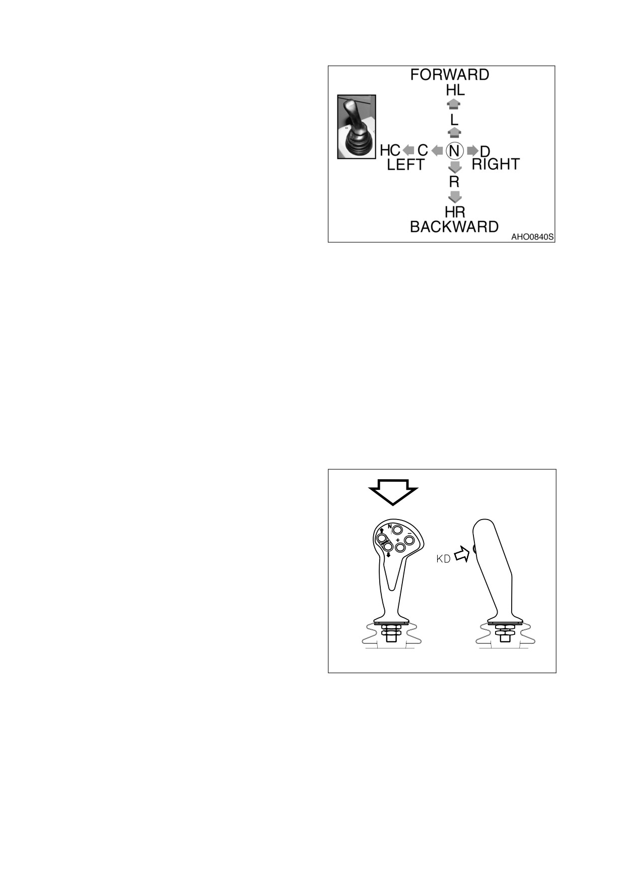
PILOT CONTROL VALVE LEVER
(JOYSTICK)
Used to position bucket and boom. This
lever is capable of raising or lowering
boom, and crowding or dumping bucket.
When machine is being traveled, the lever
(joystick) can be "LOCKED" out, to prevent
any movement of bucket or boom. To
"LOCK" out lever
(joystick), place pilot
cutoff switch in "LOCKED" position.
NOTE: If loader is equipped with log
forks the bucket dump circuit is
used to control the angle of the
forks and grasping action.
Figure 46
Pilot control valve lever (joystick) operating
pattern and description of operation.
HL.
Hold lever
in
Lower Mode
L.
Lower
HC. Hold lever in
C. Bucket Crowd
/
N.
Neutral
D.
Bucket Dump
/
Bucket Crowd /
Close Log Fork
Open Log Fork
Close Log Fork
R.
Raise
HR.
Hold lever
in
Raise Mode
1A.
ERGO-II PILOT CONTROL VALVE
LEVER (JOYSTICK) (OPTION)
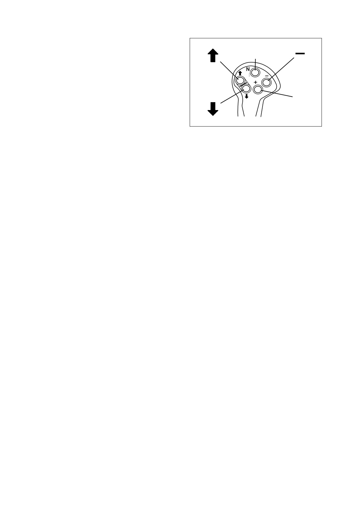
Ergo-II lever is a pilot control valve lever
that incorporates transmission control
functions. It is used to reduce hand and
arm movement for he otherwise complex
operation of machine.
A. Forward, Neutral and Reverse
Switches.
"↑" Button
− When pressing this
switch, machine
travels
"FORWARD."
"N" Button
− When pressing this
switch,
machine
is
in
AJO0591L
"NEUTRAL."
Figure 47
"↓" Button
− When pressing this
switch,
machine
travels
"REVERSE."
022-00029AE Operation and Maintenance Manual
Operating Controls 2-23
B. Traveling Speed Changing Switches.
The transmission has 4 speeds in
N
forward and 3 speeds in reverse.
"+"
Button − When pressing this
switch, machine speed increase.
"-"
Button − When pressing this
switch, machine speed decrease.
+
C. Kick-down Switch.
"KD" Button
− When pressing this
switch that is in the rear side, kick-
HAAD3761
down function is selected.
Figure 48
Ergo-II lever switch usage:
•
When Rotating the starter switch to "I" (ON) position, DISPLAY indicates "NN."
•
When DISPLAY indicates "N4" while "N" button of ERGO-II is pressed, start the engine.
•
When DISPLAY indicates "N1" while "-" button is pressed, the machine is in the traveling ready
condition.
•
When "↑" button is pressed at forward traveling while "KD" button is pressed, machine can travel
forward.
•
When "↓" button is pressed at backward traveling while "KD" button is pressed, machine can
travel backward.
•
When machine is travelled, it can convert forward and backward travel without pressing "KD"
button.
NOTE: Travel can be possible while "KD" button is pressed at NEUTRAL condition.
•
"+" Button − Increase speed.
•
"-" Button − Decrease speed.
•
Kick-down switch: "KD" Button.
2-24 Operating Controls
022-00029AE Operation and Maintenance Manual
2.
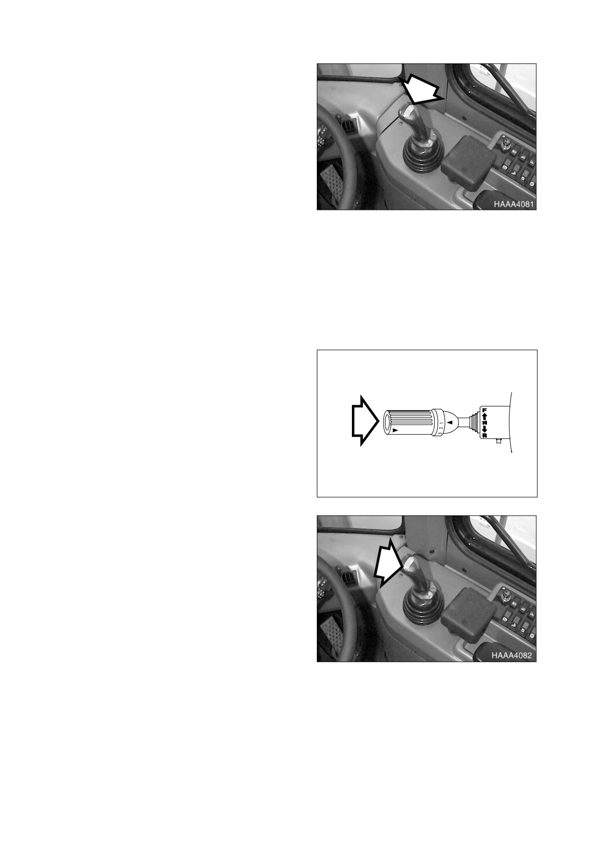
KICK-DOWN SWITCH (TWO PLACES) /
LOG FORK SWITCH (OPTION)
Kick-down Switch Function
- When
transmission is in 2nd gear, pressing this
switch (Figure 50) will shift transmission
into 1st gear. This will allow the driver to
perform a quick digging movement.
Kick-down function range:
•
Automatic: 2nd, 3rd, 4th
•
Manual: 2nd
NOTE: Kick-down is "RELEASED"
Figure 49
when transmission is placed in
"NEUTRAL” position or the
switch is pressed again
Log Fork Switch Function
- When the
button is depressed and held the log forks
are allowed to open and close when
moving the lever from side to side. See
pilot
control valve lever
(joystick)
movement pattern.
A second kick-down switch (Figure 49) is
on the end of the transmission lever.
HAAA3670
Figure 50
3.
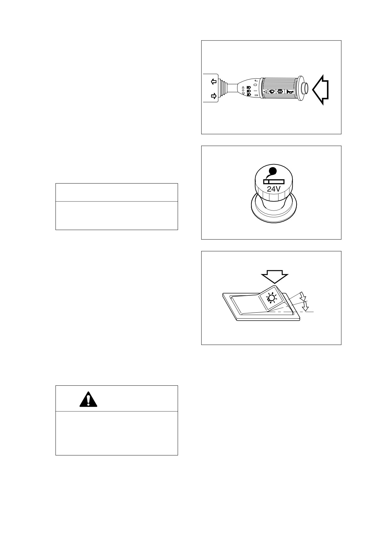
HORN BUTTON (TWO PLACES)
Pressing the left button at the tip of the
pilot control valve lever (joystick) (Figure
51) or the button at the end of the
combination switch (Figure 52) will sound
the horn.
NOTE: Starter switch must be "ON."
Figure 51
022-00029AE Operation and Maintenance Manual
Operating Controls 2-25
AHO0890L
Figure 52
4.
CIGAR LIGHTER
Push in cigar lighter. It will remain in, until it
is hot. When hot, it will pop back. It is now
ready for use.
IMPORTANT
The cigar lighter is powered by a 24
volt circuit. Never plug any 12 volt
device into the cigar lighter.
HAOA780L
Figure 53
5.
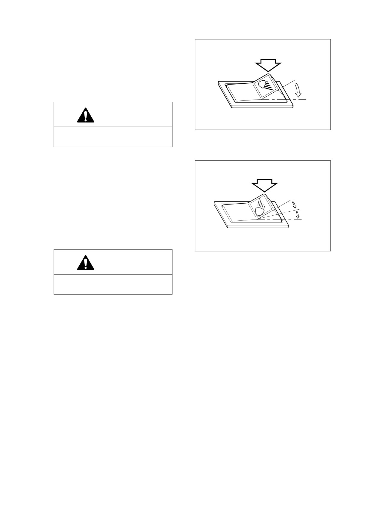
HEADLIGHT SWITCH
O. In this position, this switch turns
"OFF" clearances, tail, instrument
panel, pendant light of switches and
head lights.
O
NOTE: If the switch is not this position
I
with the engine not running, the
II
pilot buzzer will sound to
prevent batteries discharging.
I.
In this position, this switch turns "ON"
clearance, tail, instrument panel and
AQO0080L
switch lights.
Figure 54
II.
In this position, this switch turns "ON"
clearance, tail, instrument panel,
switch and headlights.
CAUTION!
Do not leave clearance, tail,
instrument panel or headlights "ON"
when the engine is not running.
Leaving lights "ON" with the engine
shutdown will discharge batteries.
2-26 Operating Controls
022-00029AE Operation and Maintenance Manual
6.
FRONT WORK LIGHT SWITCH
O. In this position, this switch turns
"OFF" work lights mounted on the
front top of cab.
I.
In this position, this switch turns "ON"
O
work lights mounted on the front top
of cab.
I
CAUTION!
HAOQ071L
Do not turn "ON" the work light when
Figure 55
traveling on public roads.
7.
REAR WORK LIGHT SWITCH
O. In this position, this switch turns
"OFF" work lights mounted on the
rear top of cab, and sides of radiator.
O
I.
In this position, this switch turns "ON"
work lights mounted on sides of
I
radiator.
II
II.
In this position, this switch turns "ON"
work lights on the rear top of cab and
sides of radiator.
AHO0850L
Figure 56
CAUTION!
Do not turn "ON" the work light when
traveling on public roads.
022-00029AE Operation and Maintenance Manual
Operating Controls 2-27
8.
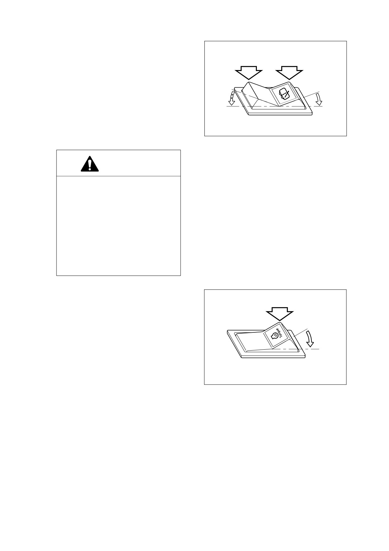
REAR WIPER SWITCH
O. In this position, this switch turns
"OFF" windshield wiper mounted on
rear windshield of operator’s cab.
I.
In this position, windshield washer
fluid sprays onto the rear windshield
O
O
while running the rear wiper. When
released, the switch returns to the
I
II
"O" position.
II.
In this position, this switch turns "ON"
windshield wiper mounted on rear
APO0200L
windshield of operator’s cab.
Figure 57
CAUTION!
The washer pump can be damaged if
it is activated while there is no fluid in
the tank. The fluid level should be
regularly checked and refilled if
necessary.
Using soap or other solvents instead
of the recommended washer fluid
may damage the wiper blades and
the paint finish.
Only use recommended washer fluid
or equivalent.
9.
ALTERNATE TORQUE SWITCH
(ECONOMIC MODE)
This alternate torque switch allows the
operator to switch between 100% throttle
torque curves and about an 80% derated
O
torque curve. This improves operating fuel
efficiency in loaded versus unloaded
I
conditions.
O. In this position torque switch is set to
the "OFF" position, and 100% torque
is permitted.
AQO0090L
I.
In this position, torque switch is
Figure 58
turned "ON," which limits engine
torque to 80% of maximum.
2-28 Operating Controls
022-00029AE Operation and Maintenance Manual
10.
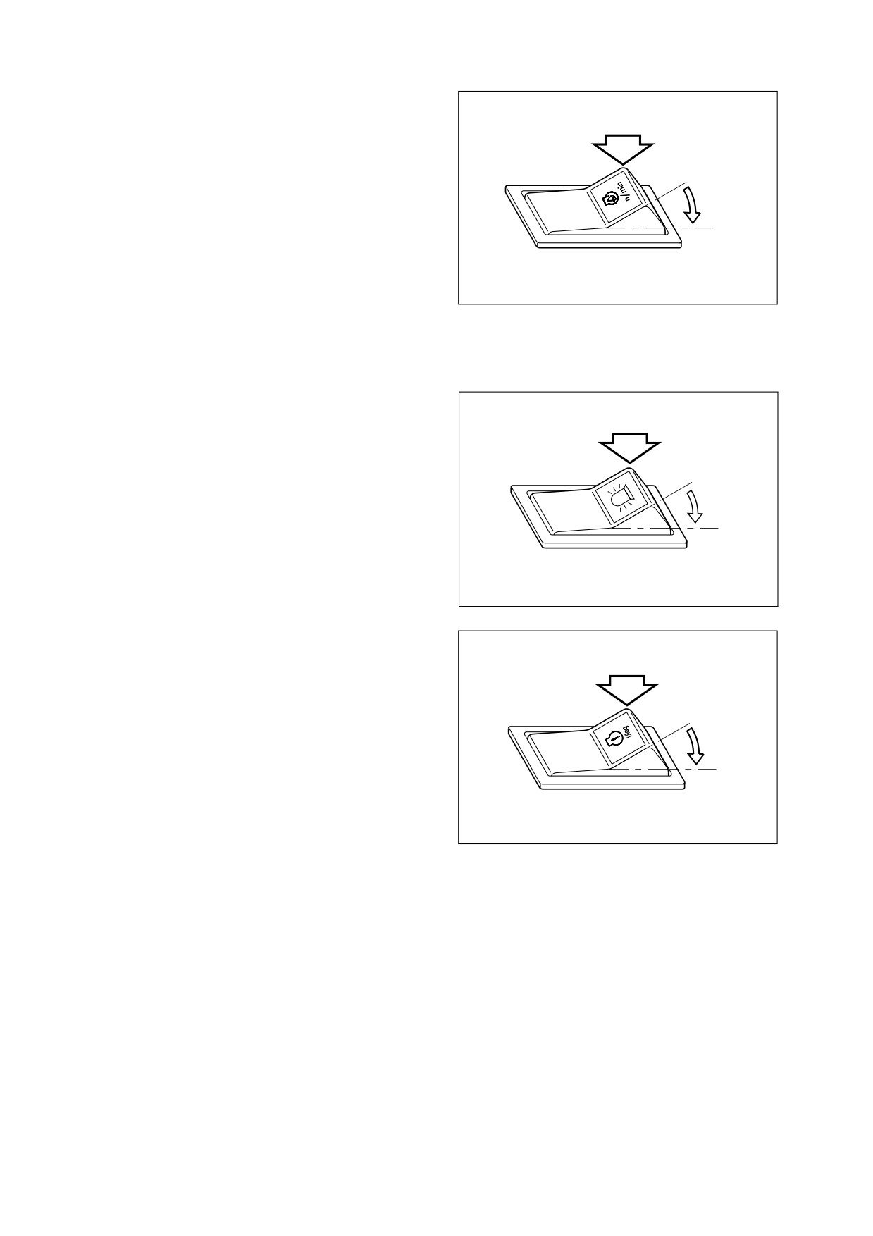
ALTERNATE IDLE SPEED SWITCH
The alternate low idle switch allows
operator to select an alternate idle speed
(about 1,200 rpm).
O
This feature is activated whenever the
normally open alternate low idle switch is
closed and 0 volts are detected by the
I
ECM on the alternate low idle signal line.
This is convenient to use when operator
wants to decrease warm-up time in the
winter.
AQO0100L
Figure 59
O. "OFF" position.
I.
"ON" position.
11.
ROTATING BEACON SWITCH (OPTION)
O. "OFF" position.
I.
When this switch is moved to "ON"
position, it activates the warning light.
O
12.
CUP HOLDER
I
Place to put beverages.
HAOA750L
Figure 60
13.
ENGINE DIAGNOSTIC SWITCH
If the engine warning light (yellow), engine
stop light (red), or the engine maintenance
light (blue), comes on when the engine is
running, it means a fault code has been
O
recorded. When this occurs, the engine
diagnostic switch allows the operator to
view the fault codes.
I
The active fault codes can be viewed using
the engine stop light (Red) as described
below.
AQO0120L
A. The engine must be shut off (not
Figure 61
running).
B. The starter switch must be in the
"ON" position.
C. The engine diagnostic switch must
be in the "I" position.
If a fault code is displayed, contact your
authorized dealer for repair.
To know the fault code information, refer to
the engine control system of shop manual.
022-00029AE Operation and Maintenance Manual
Operating Controls 2-29
14.
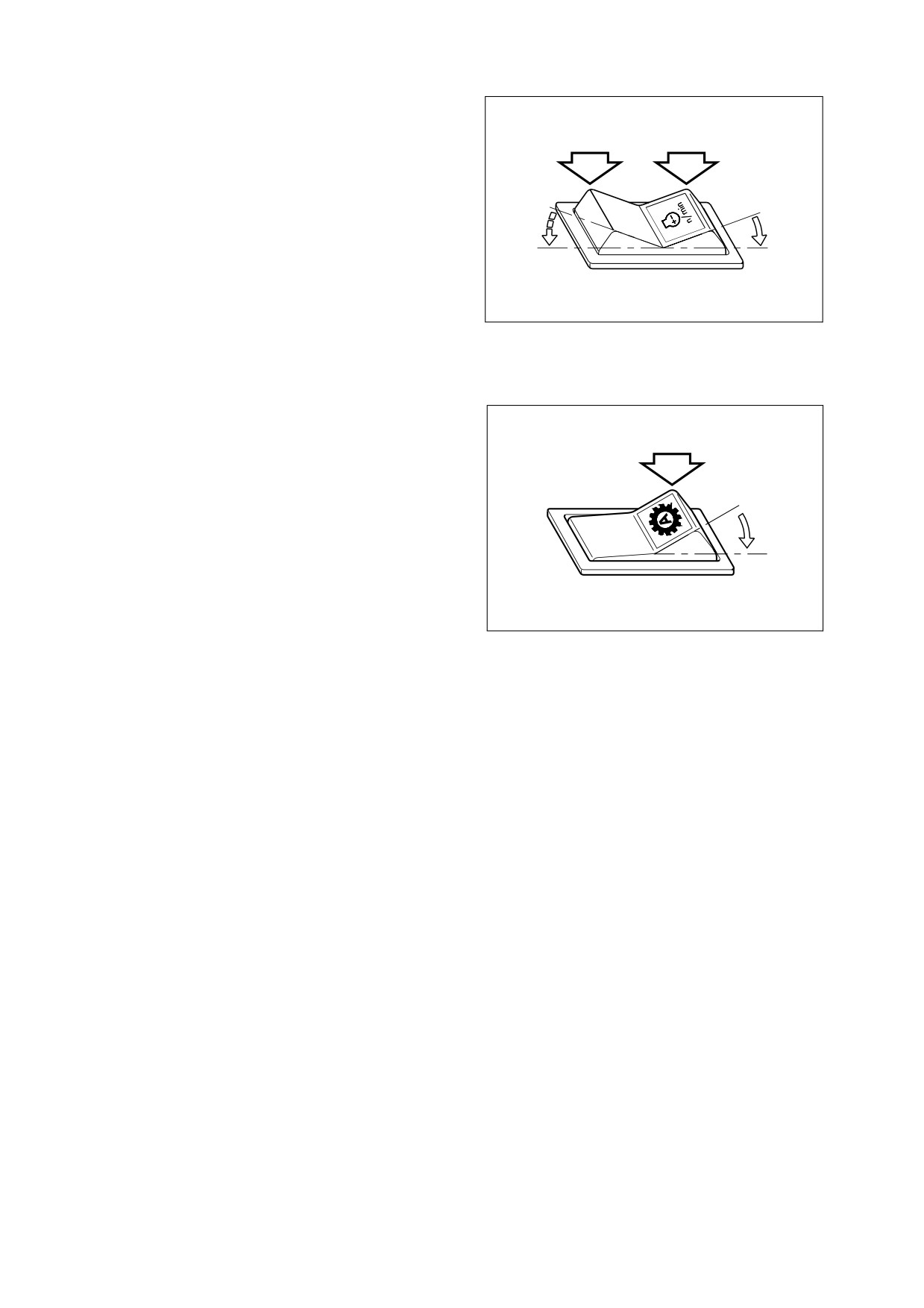
IDLE SPEED CONTROL SWITCH
The idle speed control allows the idle
speed to be adjusted in 25 rpm increments
by pressing the idle speed control switch.
The switch will only work from 800 to 900
rpm.
O
O
Pressing the "I" position of the switch will
increase (+) engine rpm.
I
II
Pressing the "II" position of the switch will
decrease (-) engine rpm.
AQO0110L
NOTE: This switch is also used to view
Figure 62
the next or previous fault code
in the diagnostic mode.
15.
AUTOMATIC TRANSMISSION SWITCH
Automatic speed range:
•
Forward - 2nd, 3rd, 4th.
•
Reverse - 2nd, 3rd.
O
O. When this switch is in "O" (MANUAL)
position, travel mode is switched to
"MANUAL" and allows operator to
I
choose speeds manually.
I.
When this switch is in "I"
(AUTO)
position,
gears
are
HLB20071L
"AUTOMATICALLY" changed to the
Figure 63
appropriate speed up to the limit set
by the transmission lever and
according to travel load and engine
rpm.
2-30 Operating Controls
022-00029AE Operation and Maintenance Manual
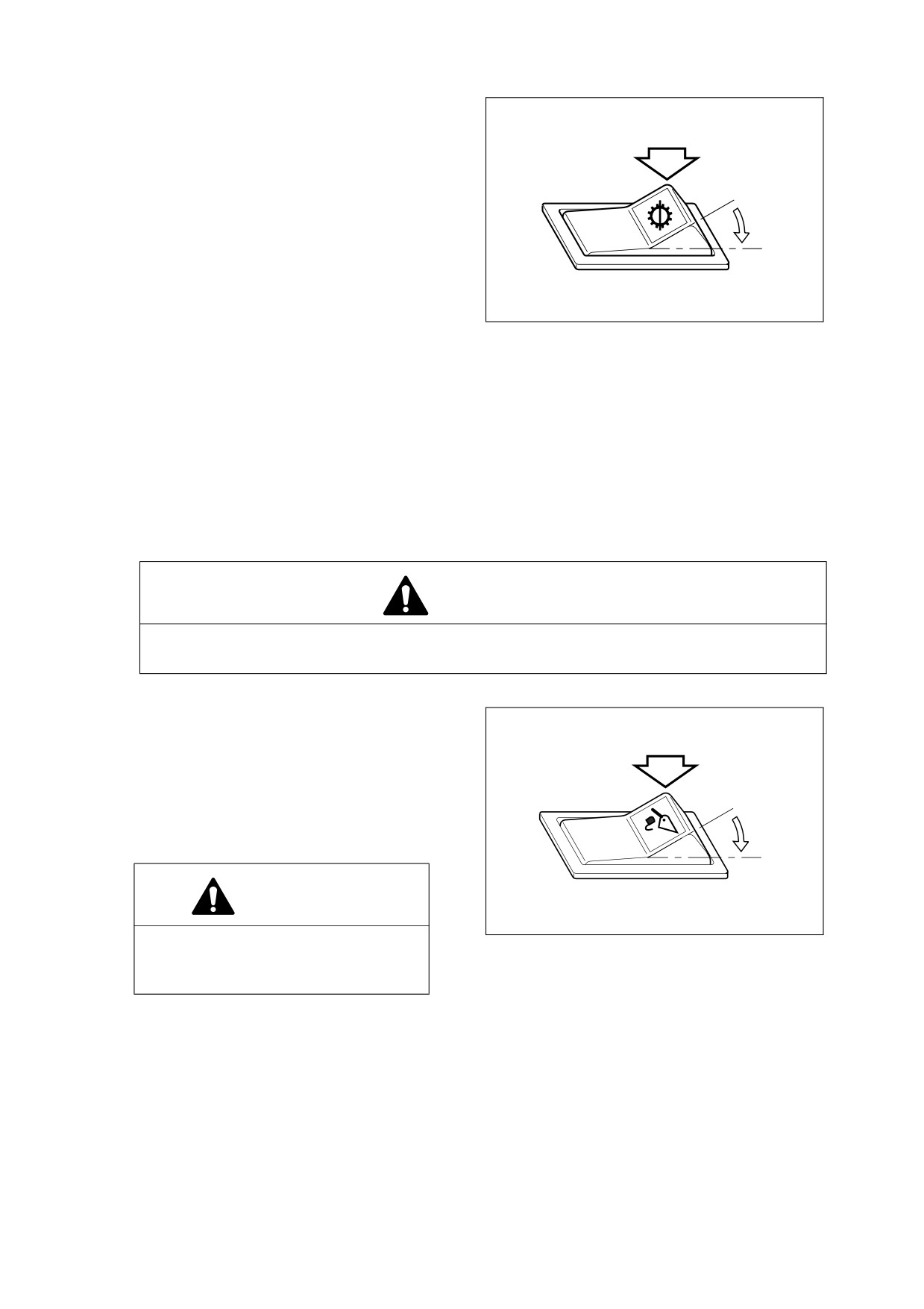
16. TRANSMISSION CUTOFF SWITCH
This switch changes over the modes of the
brake pedal, inching and no-inching.
O. In this position, the "NO INCHING"
mode is selected.
O
In the "NO INCHING" mode, the
power transmission line is still
I
connected when the brake pedal is
pressed, thus, making it easier to
start off on an incline. This mode is
also suitable for traveling, because
HA3O2018
both engine braking and the service
Figure 64
brake can be used in descending
grades.
I.
In this position, the "INCHING" mode is selected.
In this mode, the transmission is put in "NEUTRAL" by pressing the brake pedal. This mode is
suitable for load handling operation. When the accelerator pedal is pressed under this condition,
more power is concentrated on the load handling system, to quicken the boom lifting speed.
NOTE:
1) Transmission "CUTOFF" function dose not operate at 3rd and 4th gear for protection of
transmission.
2) Despite transmission "CUTOFF" switch, the right brake pedal has braking function only.
WARNING!
When pressing brake pedal while traveling or working on a slope, set this switch to "O" for
engine brake.
17. PILOT CUTOFF SWITCH
O. In this position the operator cannot
operate the pilot control valve lever
(joystick).
I.
In this position the operator can fully
O
control the movement of the pilot
control valve lever (joystick).
I
CAUTION!
HBOI110L
When driving or parking, the pilot
Figure 65
cutoff switch should be changed to
"O" position.
022-00029AE Operation and Maintenance Manual
Operating Controls 2-31
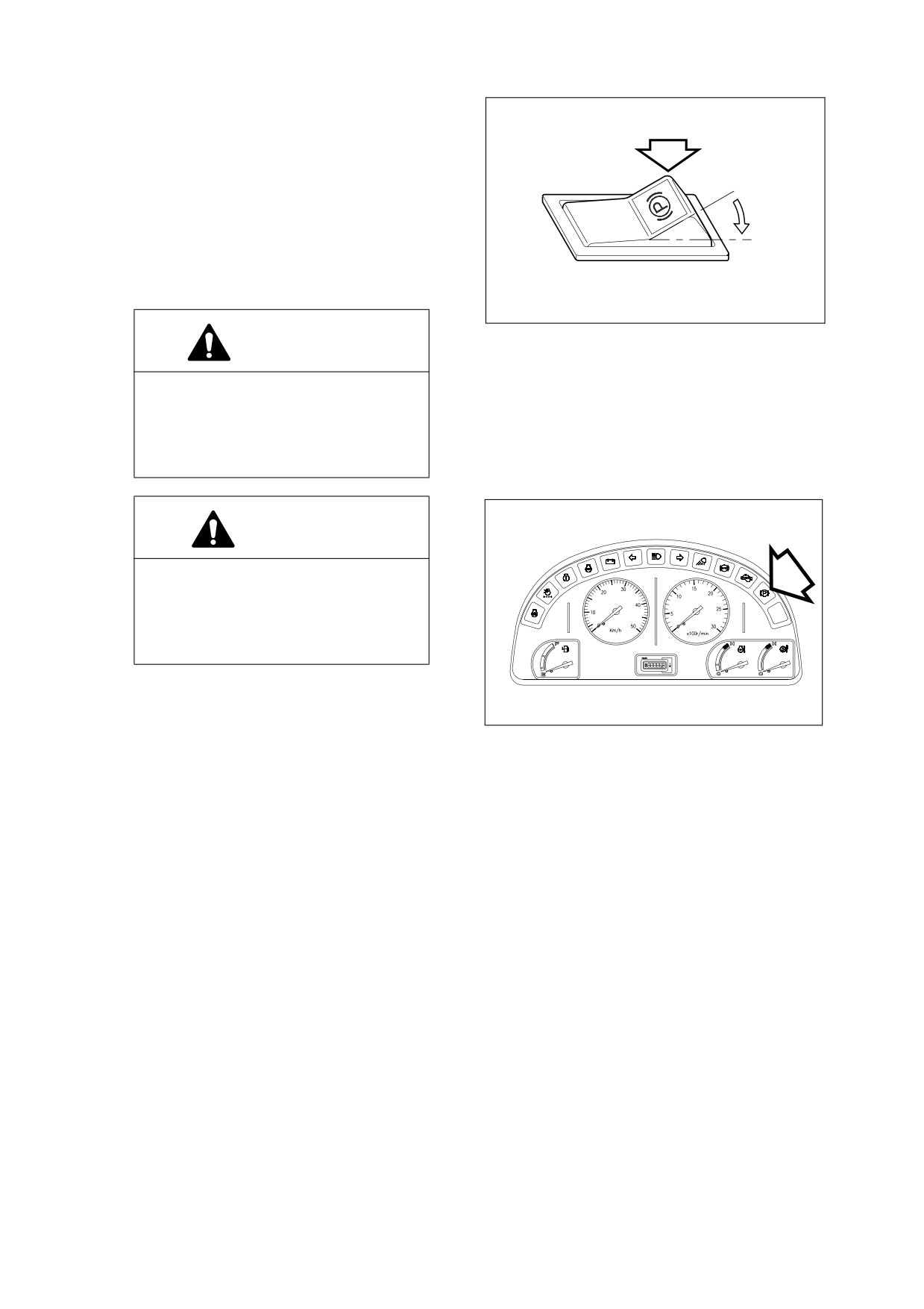
18. PARKING BRAKE SWITCH
O. In this position, the parking brake is
"RELEASED" and the monitor light
on the front instrument panel turns
"OFF."
O
I.
In this position, the parking brake is
"APPLIED" and the monitor light on
I
the front instrument panel comes
"ON." This brake can also be used as
an emergency brake.
HAOP042L
Figure 66
WARNING!
Set the parking brake switch in the
"I" (APPLIED) position before leaving
the loader. Make sure to "APPLY" the
parking brake switch before trying to
start the loader.
CAUTION!
Do not use this parking brake to
brake the loader, except in an
emergency; otherwise, it might cause
premature wear or damage of the
brake.
AQO0171L
Figure 67
2-32 Operating Controls
022-00029AE Operation and Maintenance Manual
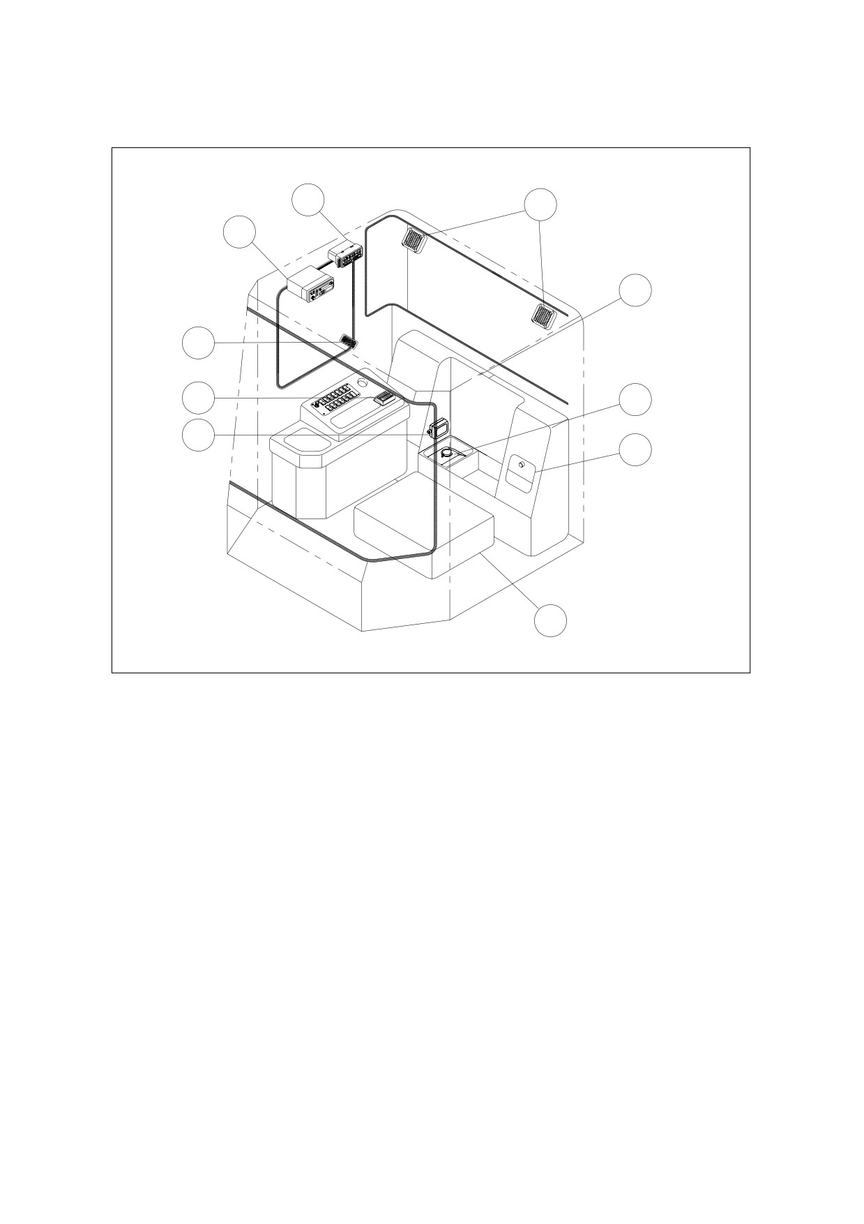
VARIOUS CABIN LOCATIONS
3
4
2
5
1
10
6
9
7
8
AQO0150L
Figure 68
1.
CAB LIGHT
6.
WASHER TANK
2.
STEREO
7.
HOT/COLD REFRIGERATOR
3.
HEATER AND AIR CONDITIONER
8.
ELECTRICAL BOX
CONTROL PANEL
9.
FUSE BOX TWO
4.
SPEAKERS
10.
FUSE BOX ONE
5.
STORAGE BOX
022-00029AE Operation and Maintenance Manual
Operating Controls 2-33
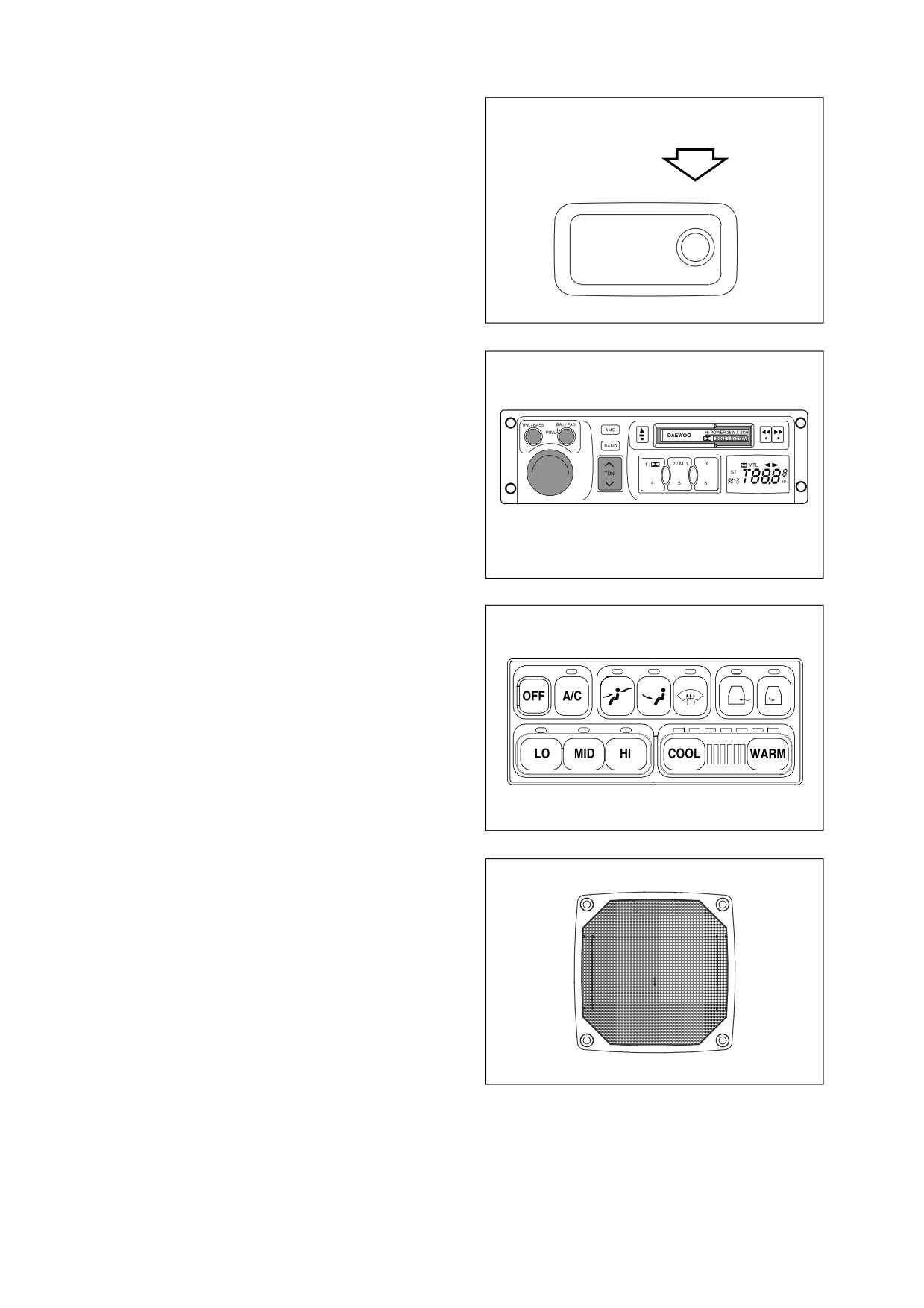
1.
CAB LIGHT
A light is on the front of the ceiling. Turn
the light "ON" and "OFF" by pressing its
switch. The light will work despite starter
switch position.
NOTE: If light is left on for a long time
while the engine is not running,
the batteries will be discharged.
HBOI400L
Figure 69
2.
STEREO
For operation of stereo see “Stereo” on
page 2-42.
HAOA951L
Figure 70
3.
HEATER AND AIR CONDITIONER
CONTROL PANEL
For operation of heater and air
conditioning see
“Heater and Air
Conditioner Operation” on page 2-37.
HAOA771L
Figure 71
4.
SPEAKERS
Emits sound generated by stereo.
HBOM350L
Figure 72
2-34 Operating Controls
022-00029AE Operation and Maintenance Manual
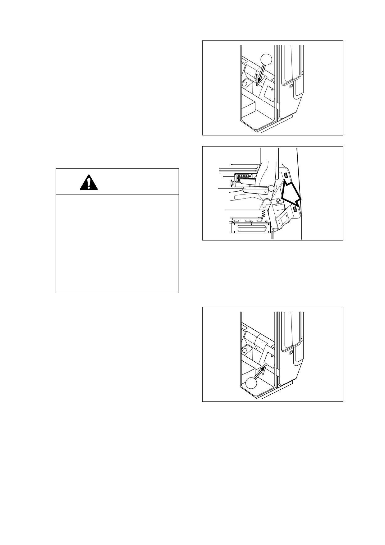
5.
STORAGE BOX
There is a storage box
(1, Figure
73)
behind the seat. Keep the operation
1
maintenance manual and other documents
in this compartment.
HBOI431L
Figure 73
6.
WASHER TANK
Contains windshield washer fluid.
CAUTION!
The washer pump can be damaged if
it is activated while there is no fluid in
the tank. The fluid level should be
regularly checked and refilled if
necessary.
HBOM680I
Using soap or other solvents instead
Figure 74
of the recommended washer fluid
may damage the wiper blades and
the paint finish.
Only use recommended washer fluid
or equivalent.
7.
HOT/COLD REFRIGERATOR
There is a hot/cold refrigerator (1, Figure
75) behind and to the left of the seat. Air
conditioner and heating unit must be
operated after starting the engine for this
function. Keep the cover close for proper
function.
1
HBOI432L
Figure 75
022-00029AE Operation and Maintenance Manual
Operating Controls 2-35
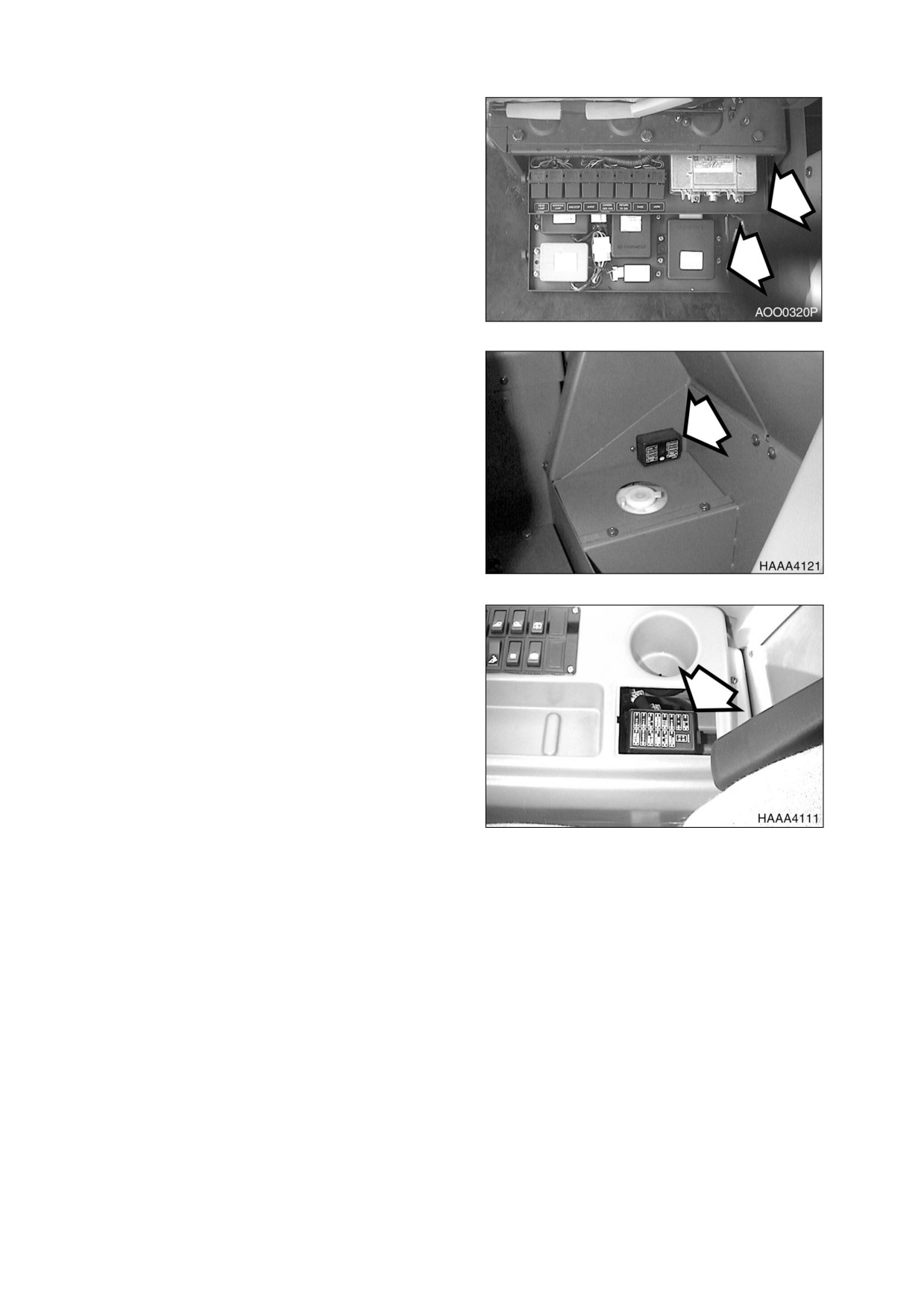
8.
ELECTRIC BOX
Under the seat are two pullout trays that
contain relays for unit. See
“Fuse Box/
Relay” on page 2-50.
Figure 76
9.
FUSE BOX TWO
Fuse box two is just above the windshield
washer fluid tank. For a detailed
explanation of fuses see “Fuse Box/Relay”
on page 2-50.
Figure 77
10. FUSE BOX ONE
The fuse box is at the rear side of right
control stand. For a detailed explanation of
fuses see “Fuse Box/Relay” on page 2-50.
Figure 78
2-36 Operating Controls
022-00029AE Operation and Maintenance Manual
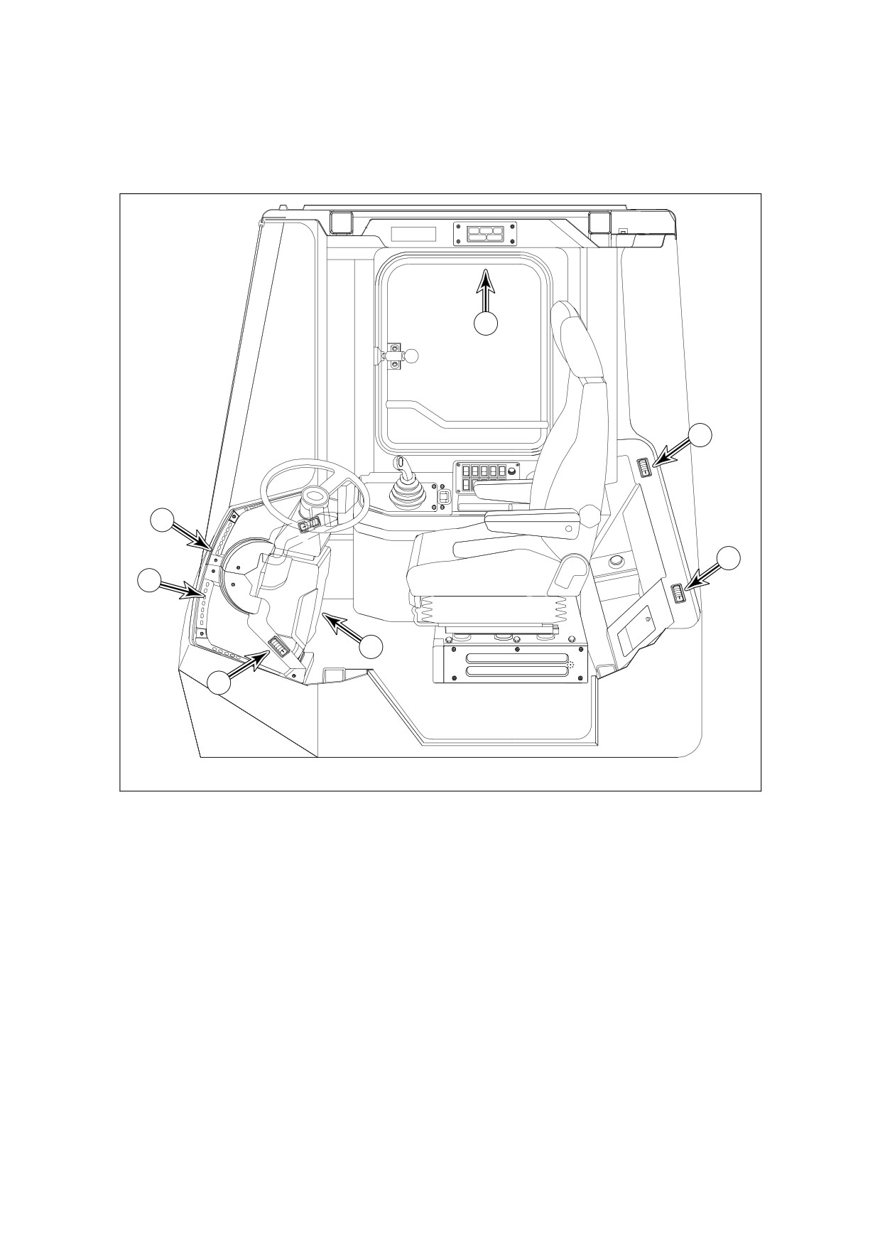
HEATER AND AIR CONDITIONER OPERATION
LOCATION OF CONTROLS AND VENTS
1
5
3
5
3
4
2
HBOI310L
Figure 79
1.
OPERATION PANEL
4.
FOOT NOZZLE
2.
FRONT NOZZLE (AIR-CON)
5.
REAR NOZZLE
3.
FRONT NOZZLE
The heater and air-conditioner are combined into one unit to the rear of the operator’s seat. If necessary,
the operator can control inner temperature using the operation of panel installed in the right control stand.
022-00029AE Operation and Maintenance Manual
Operating Controls 2-37
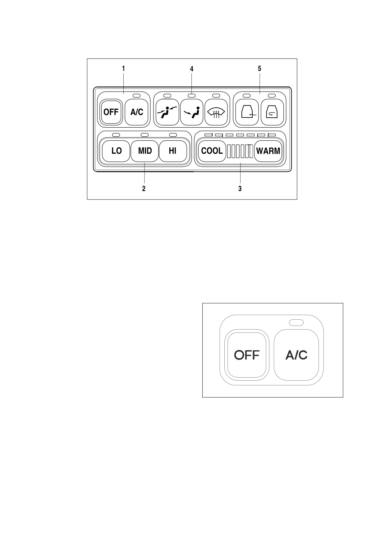
OPERATION PANEL
HAOA801L
Figure 80
1.
FAN AND AIR-CONDITIONER SWITCH
4.
SELECTION SWITCH FOR WIND
2.
BLOWER FAN SWITCHES
DIRECTION
3.
TEMPERATURE CONTROL SWITCH
5.
VENTILATION SELECTION SWITCH
When a switch is selected, the LED above that switch will turn "ON" and give an activation sound.
When the light switch is turned "ON," the panel LED’s will turn "ON."
1.
FAN AND AIR CONDITIONER SWITCH
A. "OFF" Switch
- Turns "OFF" the
heater and air conditioner unit.
B. "A/C" Switch - Turns "ON" the air
conditioner when one of the blower
switches is activated.
ARO0510L
Figure 81
2-38 Operating Controls
022-00029AE Operation and Maintenance Manual
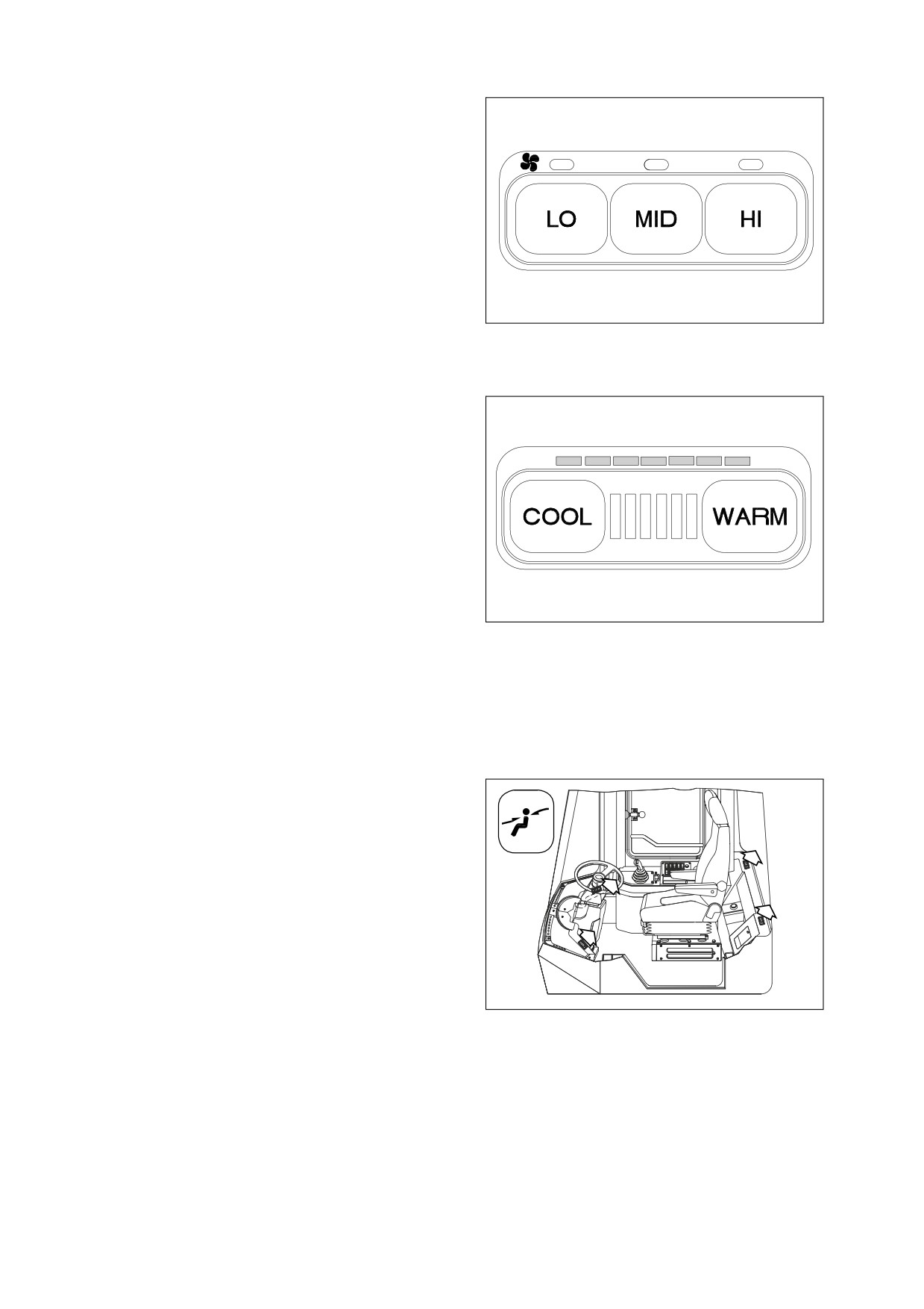
2.
BLOWER FAN SWITCHES
These switches are used to control the
speed of the blower fan.
A. "LO" Switch - Used for low blower
speed.
B. "MID" Switch - Used for intermediate
blower speed.
C. "HI" Switch - Used for high blower
speed.
NOTE: If you do not select a blower
ARO0520L
speed the heater and air
Figure 82
conditioner will not work.
3.
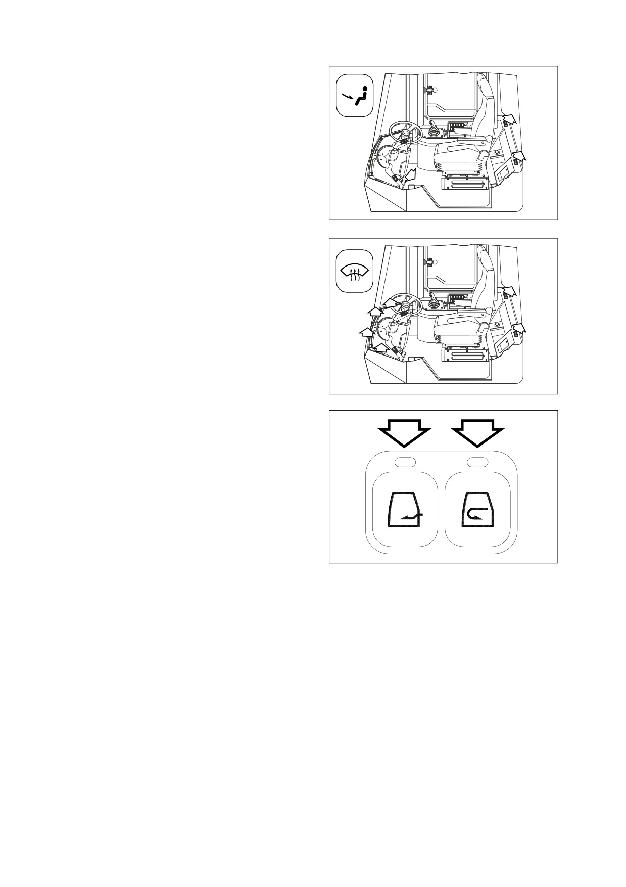
TEMPERATURE CONTROL SWITCH
The temperature control consists of
24
stages. A LED is turned "ON" for every
three stages. Whenever pushing it, it
changes in stages. Pushing it continuously,
it changes continuously.
A. "COOL" Switch
-
Lowers the
temperature.
B. "WARM" Switch
-
Raises the
temperature.
ARO0530L
LED COLOR STATUS
Figure 83
Green LED - Air conditioner. Full
green, maximum operation of
air-conditioner.
Red LED
- Heater. Full red,
maximum operation of heater.
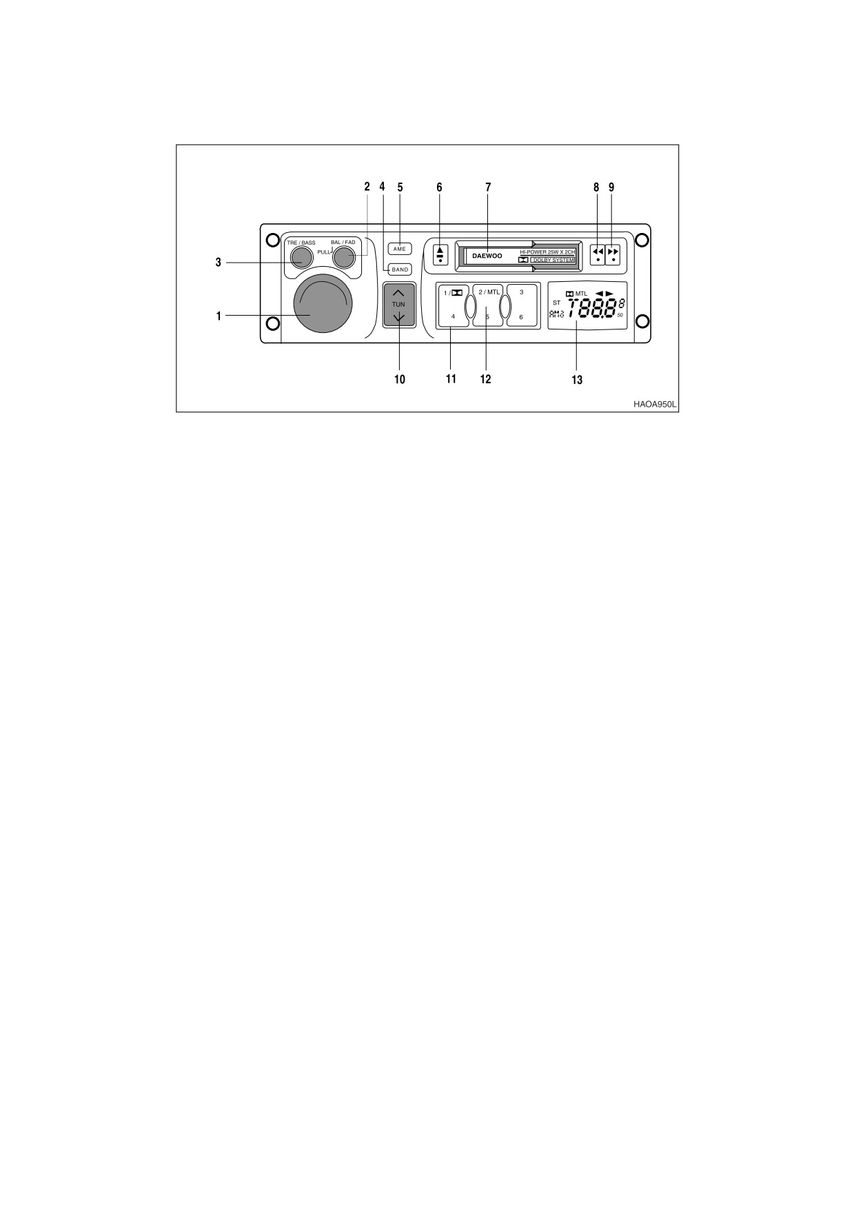
4.
SELECTION SWITCH FOR WIND
DIRECTION
A. Used to direct air flow to upper
portion of operator’s cab.
HBOI320L
Figure 84
022-00029AE Operation and Maintenance Manual
Operating Controls 2-39
B. Used to direct air flow to lower
portion of operator’s cab.
HBOI330L
Figure 85
C. Used to direct air flow for defrosting
front window of operator’s cab.
HBOI340L
Figure 86
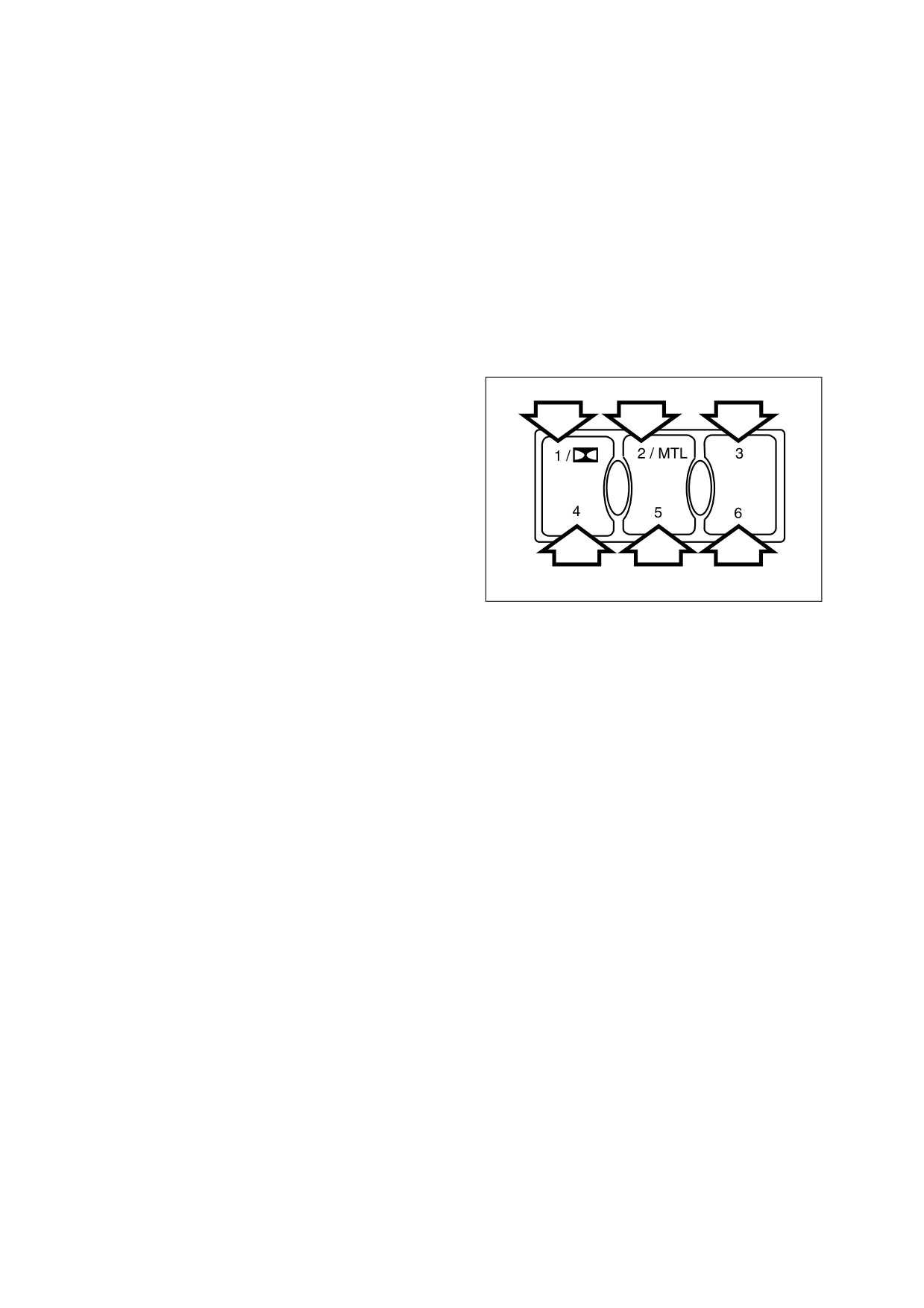
5.
VENTILATION SELECTION SWITCH
A. "A" Switch
- Draws fresh air into
A
B
operator’s compartment.
B. "B" Switch - Recirculates air within
the operator’s compartment. Used to
rapidly reduce condensation on
windows.
ARO0560L
Figure 87
MEMORY FUNCTION OF USED MODE
The air conditioner panel has a memory function. When the starter switch is turned "OFF" the settings for
the panel will be stored. When the machine is started, the last setting will be used.
2-40 Operating Controls
022-00029AE Operation and Maintenance Manual
ADDITIONAL OPERATING INSTRUCTION
A proper indoor temperature in summer is 5 - 6° C (41 - 43° F) less than the outdoor temperature.
Operate the air conditioner from 20 - 30 minutes a week to circulate the refrigerant in the system.
NOTE: The blower switch should be on "LO" speed.
NOTE: In the event that the unit is being operated in a dusty environment, the cleaning and
replacement should be performed more frequently. If filter element is damaged, replace
damaged filter by a new one.
If operating the air conditioner or heater for a long time, operate the ventilation switch, and when smoking,
vent the air to the outside to prevent irritation to eyes.
022-00029AE Operation and Maintenance Manual
Operating Controls 2-41
STEREO
Figure 88
1.
ON-OFF / VOLUME CONTROL KNOB
7.
CASSETTE SLOT
2.
BALANCE / FADER CONTROL
8. & 9. PLAY DIRECTION BUTTON
3.
BASS/TREBLE CONTROL
10. AUTOMATIC SELECTION
4.
AM/FM BAND SELECTION
11. DOLBY B SELECTION
5.
AUTOMATIC MEMORY (AME)
12. METAL SELECTION
6.
TAPE EJECT BUTTON
13. LCD DISPLAY PANEL
1.
ON-OFF / VOLUME CONTROL KNOB
When this button is pressed, stereo will be turned "ON."
When this button is pressed a second time, power turns "OFF."
Increase volume by rotating control clockwise.
When stereo is turned "ON," LCD display will indicate radio stations and/or tape functions.
2.
BALANCE / FADER CONTROL
This control adjusts both side to side balance of stereo sound and front to back fading.
Rotating control counterclockwise will increase volume to the left speakers, clockwise increases
volume to the right speakers.
Press on control and it will pop out; you can now adjust the fader (front/rear) balance.
Rotating control counterclockwise increases volume to the rear speakers, clockwise increases
volume to the front speakers.
2-42 Operating Controls
022-00029AE Operation and Maintenance Manual
3.
BASS/TREBLE CONTROL
This control adjust bass and treble tone levels.
To adjust treble tone level rotate control counterclockwise to decrease treble and clockwise to
increase treble.
To adjust bass tone level press on control and it will pop out. Rotate control counterclockwise to
decrease bass and clockwise to increase bass.
4.
AM/FM BAND SELECTION
This button sets radio to either AM-1, AM-2, FM-1 or FM-2 frequency bands. Each frequency bands
will enable the stereo to store 6 preset radio station frequencies. Each time the button is pressed the
stereo will move to the next band.
5.
AUTOMATIC MEMORY (AME)
This function automatically finds the six
strongest radio signals in the frequency
selected and stores them in memory.
Select band (AM-1, AM-2, FM-1, FM-2).
Press and hold AME button for
approximately two seconds and stereo will
search out strongest stations in area.
These stations can then be recalled by
pressing buttons (1 thru 6, Figure 89).
NOTE: To manually store radio station
HAOC990L
settings, use band selector to
Figure 89
select frequency band to be
listened to. Then use tuning
control to select desired station.
Press and hold any preset keys
for approximately 2 seconds; a
beep will sound when station
has been set.
6.
TAPE EJECT BUTTON
Eject tape from cassette deck by pressing this button. Stereo returns to tuner mode.
7.
CASSETTE SLOT
Press "ON/OFF" switch for power. Insert a tape with exposed tape facing right. The tape will start to
play. "TAPE" is displayed on LCD display.
8. & 9. PLAY DIRECTION BUTTON
Pressing this control button to either right or left will fast forward or rewind tape. The button will lock
into this position. To stop action, press opposite side button and tape will return to normal play mode.
Pressing both control buttons at the same time will reverse direction of tape.
10. AUTOMATIC SELECTION
Press this control to change channels manually to either higher or lower frequencies.
022-00029AE Operation and Maintenance Manual
Operating Controls 2-43
11. DOLBY B SELECTION
If the tape being listened to has been recorded with Dolby B, press preset selector button 1 to turn
Dolby B control on. Dolby symbol will appear on display. Press this control a second time to turn
Dolby B control "OFF."
12. METAL SELECTION
If tape being listened to is either a metal or chromium type of tape, press preset selector button 2 to
select "MTL" setting. "MTL" will appear on display. Press this control a second time to turn this setting
"OFF."
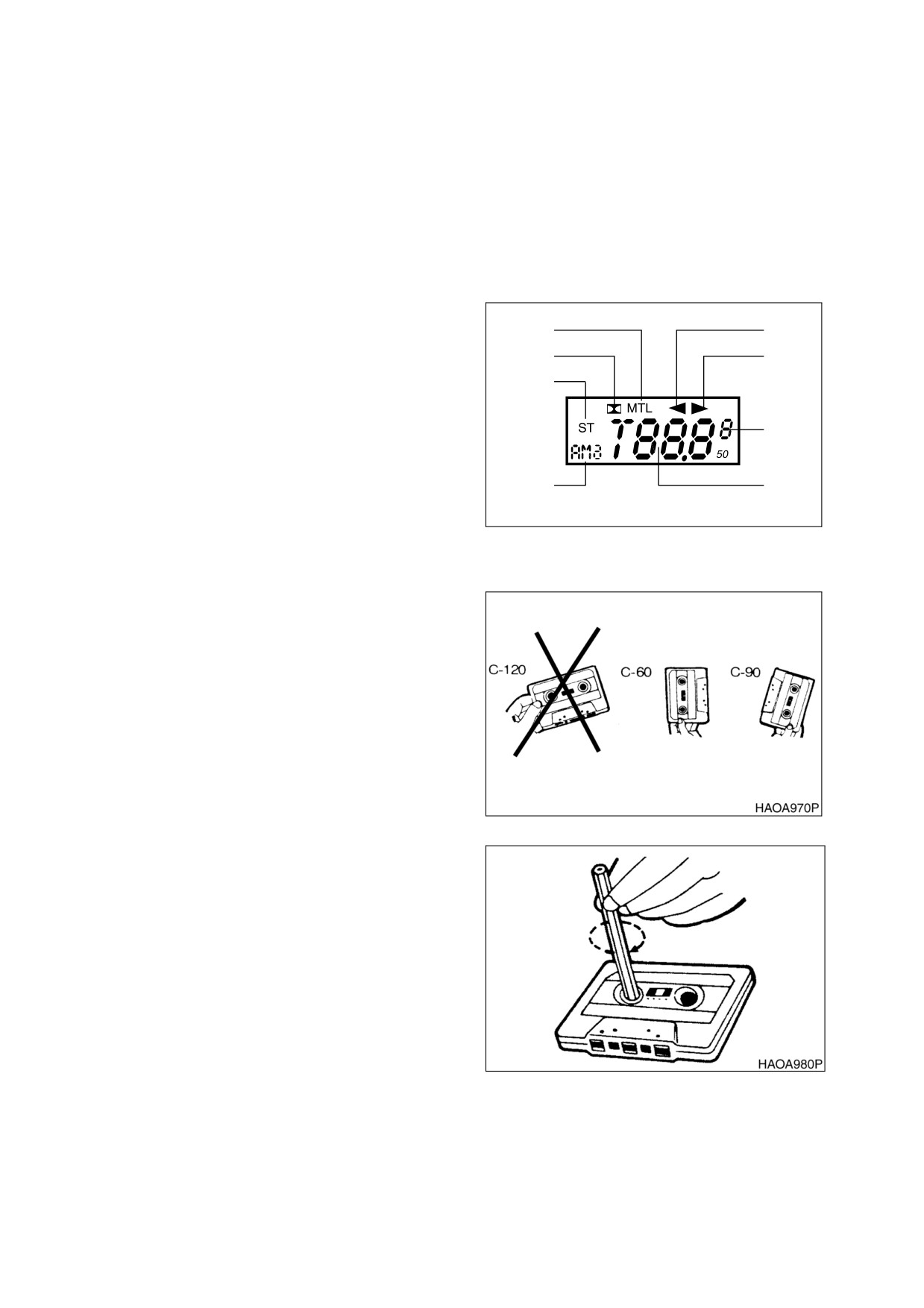
13. LCD DISPLAY PANEL
A. Tape Reverse Direction Indicator
H
A
B. Tape Forward Direction Indicator
G
B
F
C. Preset Radio Memory Channel
Indicator
D. Radio Station Frequency
C
E. AM/FM Band Indicator
E
D
F.
Stereo Radio Signal
G. Dolby Noise Reduction Indicator
HAOA960L
Figure 90
H. Metal Tape Indicator
CARE OF STEREO
Do not use a tape that has a longer playing time
than C-90 (90 minutes). Avoid use of C-120
tapes because tapes are made of a thinner
material that may break and get tangled inside
stereo.
Figure 91
Make sure tapes are wound tight. If you use a
loose tape, it may cause a problem in a deck. If
they are loose, use a pencil or similar device to
wind up slack.
Do not use poor quality tapes.
Figure 92
2-44 Operating Controls
022-00029AE Operation and Maintenance Manual
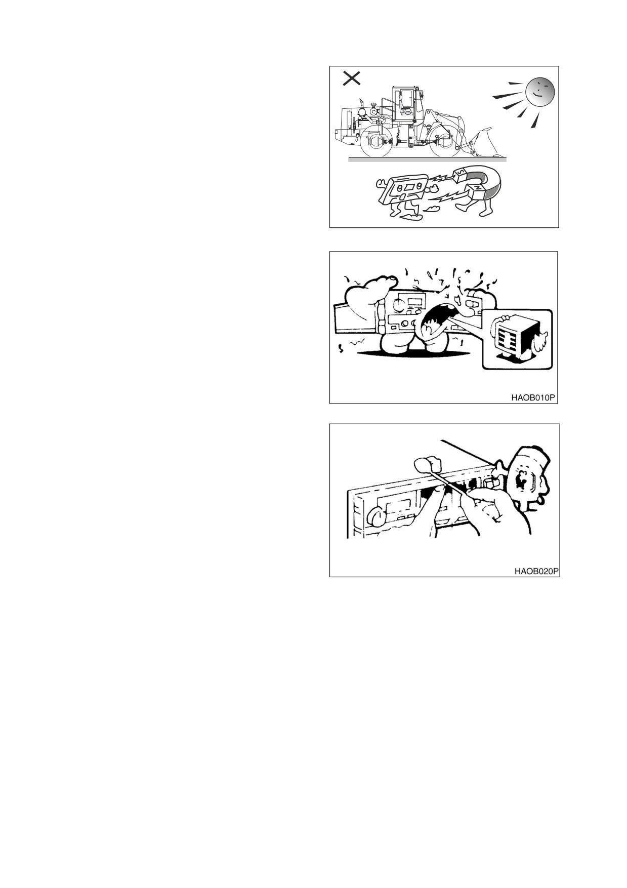
Do not store cassette tapes in the following
places or under the following conditions.
Damage to tape and stereo may result.
•
Direct sunlight.
•
Humid place.
•
Dusty place.
•
Around heater or heater vents which
discharge heat.
•
Around speakers and other magnet
devices that generate a strong
HLB2014L
magnetic field (solenoid valves).
Figure 93
Clean head and pinch roller periodically. They
continuously contact the tape. If they are not
kept clean, stereo and tapes may be damaged.
Keep them clean for optimum performance.
Figure 94
If head gets dirty, clean it with a soft cotton swap
through cassette slot.
It is recommended to use a cassette deck
cleaning tape for easy and efficient cleaning of
head, capstan and pinch roller.
When you turn "OFF" power, be sure to take out
cassette tape by pressing eject button.
When not using a cassette tape, keep it stored
in a plastic case.
Figure 95
022-00029AE Operation and Maintenance Manual
Operating Controls 2-45
SEAT ADJUSTMENT
WARNING!
Whenever operator or operating condition
has changed, check to see that seating
position is suitable for the condition at
hand. Always fasten your seat belt while
operating vehicle. Adjust backrest so that
the operator can fully reach and operate
pedals.
HAOB110L
Figure 96
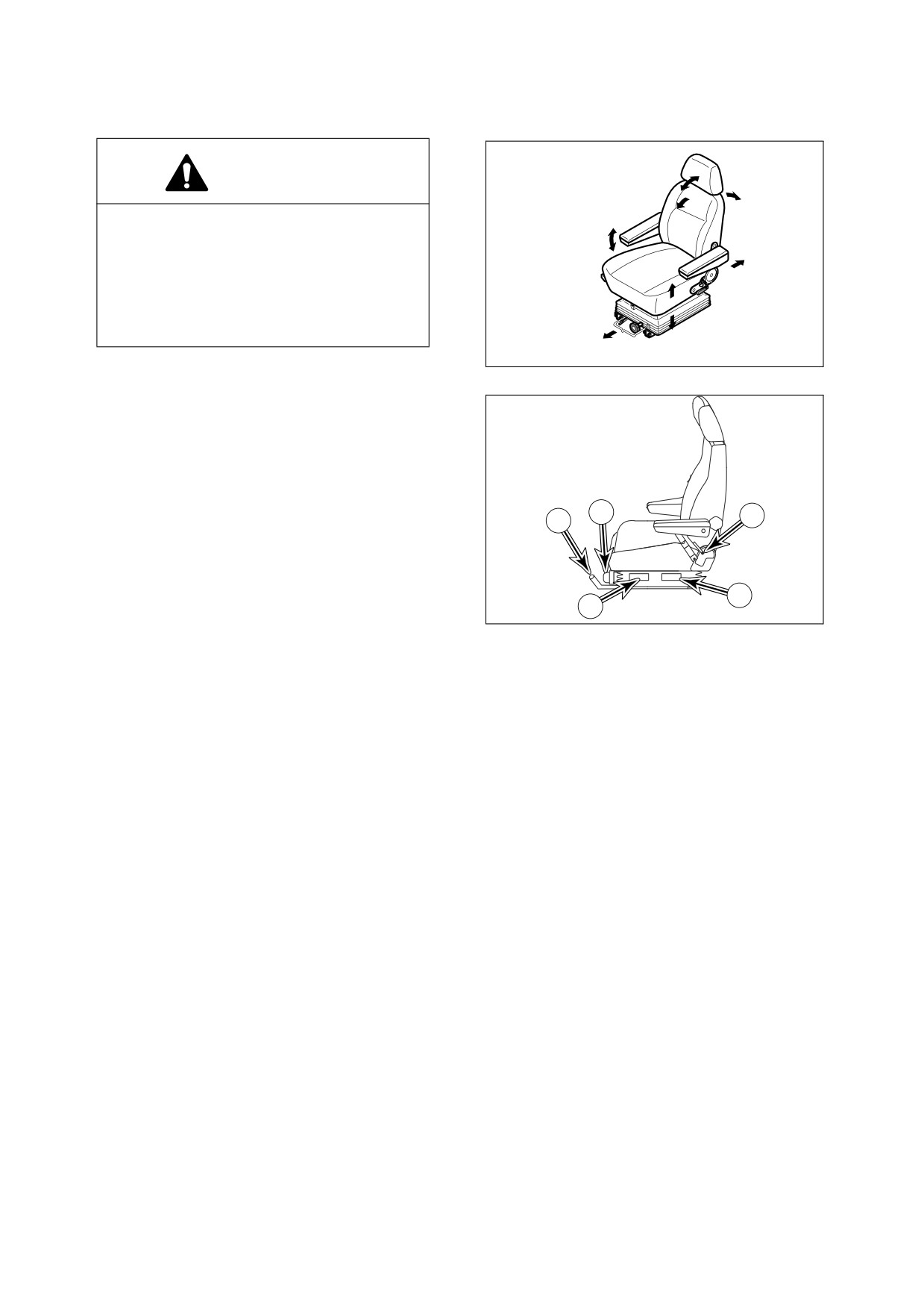
1.
ADJUSTING SEAT FORWARD/
BACKWARD LEVER
Holding lever (3, Figure 97), raise it up,
while pushing or pulling seat to desired
position. Release lever once desired
position is reached. Adjustment range is
4
5
160 mm (6.3 in).
1
2 & 3.ADJUSTING SEAT'S ANGLE AND
HEIGHT LEVER
3
2
Pulling left lever (3, Figure 97) up allows
HBOI350L
rear part of seat to be moved up or down.
Figure 97
Pulling lever (2) up allows front part of seat
to be moved up or down. Adjust seat
according to operator’s size and work
conditions. Adjustment range is
60 mm
(2.36 in) for both front and rear.
4.
WEIGHT ADJUSTMENT KNOB
Turning knob (4, Figure 97) to right makes suspension harder. Turning knob to left makes suspension
softer. Adjust according to operator’s weight by checking weight indicator dial. Adjustment range is
from 50 - 120 kg (110 - 265 lb).
5.
BACKREST ADJUSTMENT LEVER
Pulling up right lever (5, Figure 97) allows seat backrest to be moved forward or backward.
2-46 Operating Controls
022-00029AE Operation and Maintenance Manual

6.
ANGLE ADJUSTMENT OF ARMREST
Adjustment angle of left and right armrest
(6, Figure 98) is done by turning a dial in
bottom of armrest. When you adjust angle,
manually raise armrest before turning dial.
7.
HEADREST
Headrest (7, Figure 98) can be adjusted
forward/backward and up/down. Move it
by holding both sides.
HAOB130L
Figure 98
022-00029AE Operation and Maintenance Manual
Operating Controls 2-47
SEAT BELT
WARNING!
Seat belt is for operator's safety and should be worn at all times. Before driving machine, adjust
seat to desired position for maximum comfort and machine control, then fasten seat belt. Seat
belts must be worn across pelvic region and adjusted snugly to lessen chance and severity of
injury in event of an accident. Never fasten a seat belt across abdomen.
Under no circumstances should operator be standing in cab when operating wheel loader.
Do not adjust seat position while vehicle is moving because a loss of control may result. Stop
machine, apply parking brake, and then adjust seat.
Always, check condition of seat belt and belt bracket before fastening it. Do not use it with twists
in it. Replace belt or bracket if damaged or worn.
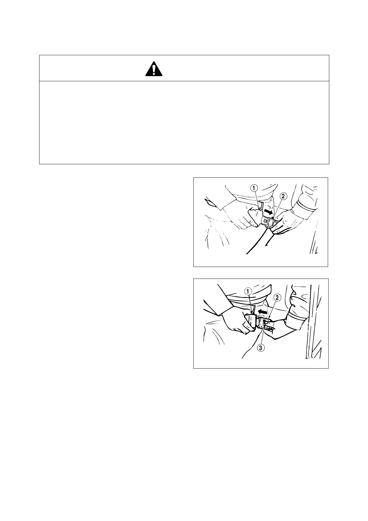
SEAT BELT LOCKING AND UNLOCKING
Insert belt end (1, Figure 99) into buckle (2). Pull
belt to check that belt end is locked into buckle.
Adjust belt length so that it is comfortably tight
against operator’s pelvic region (hipbone).
HAOB140L
Figure 99
Press button (3, Figure 100) in center of buckle
(2) and pull out belt (1) to unlock.
HAOB150L
Figure 100
2-48 Operating Controls
022-00029AE Operation and Maintenance Manual
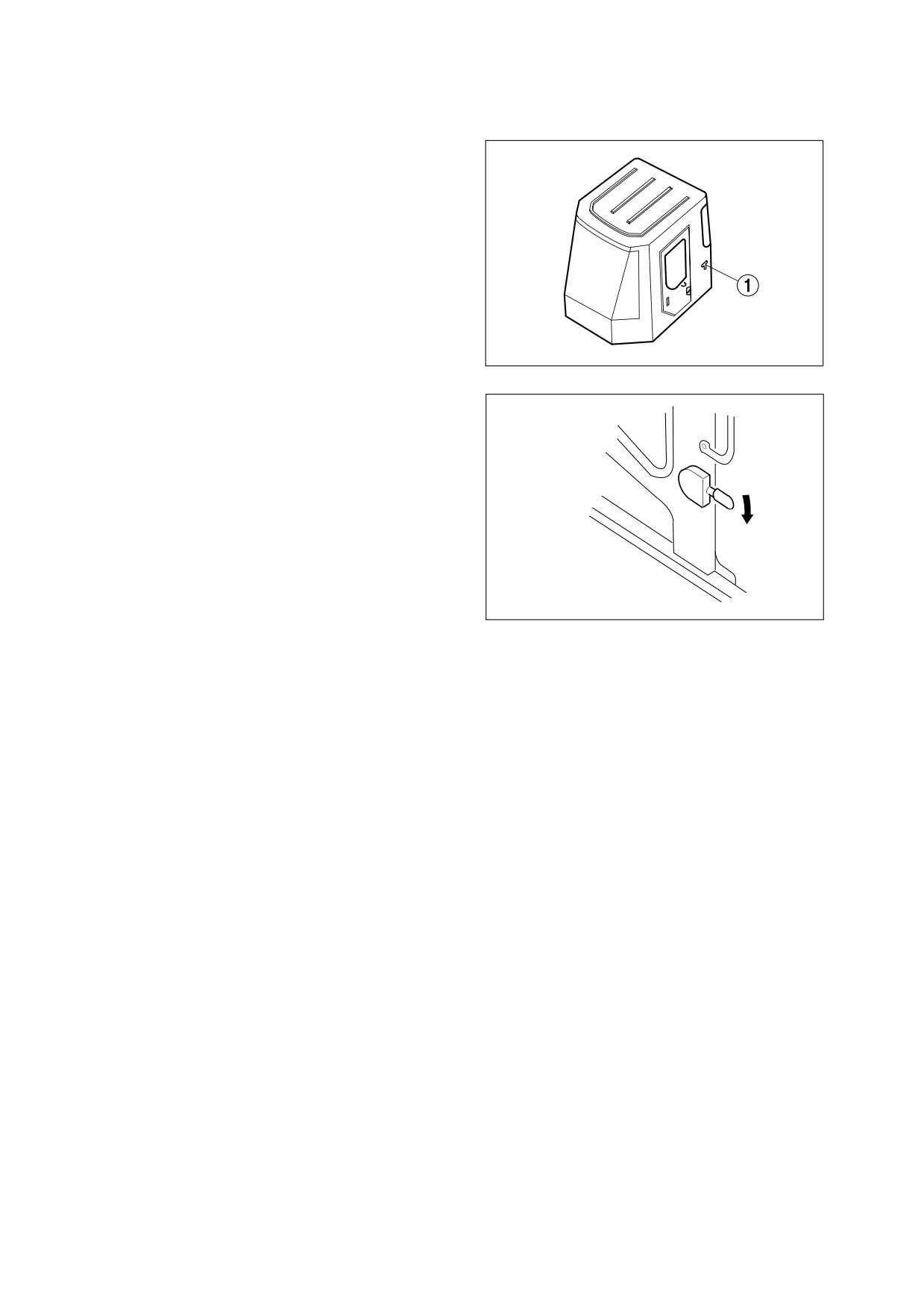
DOOR SIDE LATCH
1.
The door side latch (1, Figure 101) is used
to secured the door to the side of the cab
when it is opened (Only cabin machine).
NOTE: Keep the door closed and
locked when machine is not in
use.
HA3O2042
Figure 101
2.
To release door from side of cab, push the
latch lever (Figure 102) down. The latch
lever is to the left of the operator’s seat.
HAOB250L
Figure 102
022-00029AE Operation and Maintenance Manual
Operating Controls 2-49
FUSE BOX/RELAY
FUSE BOXES
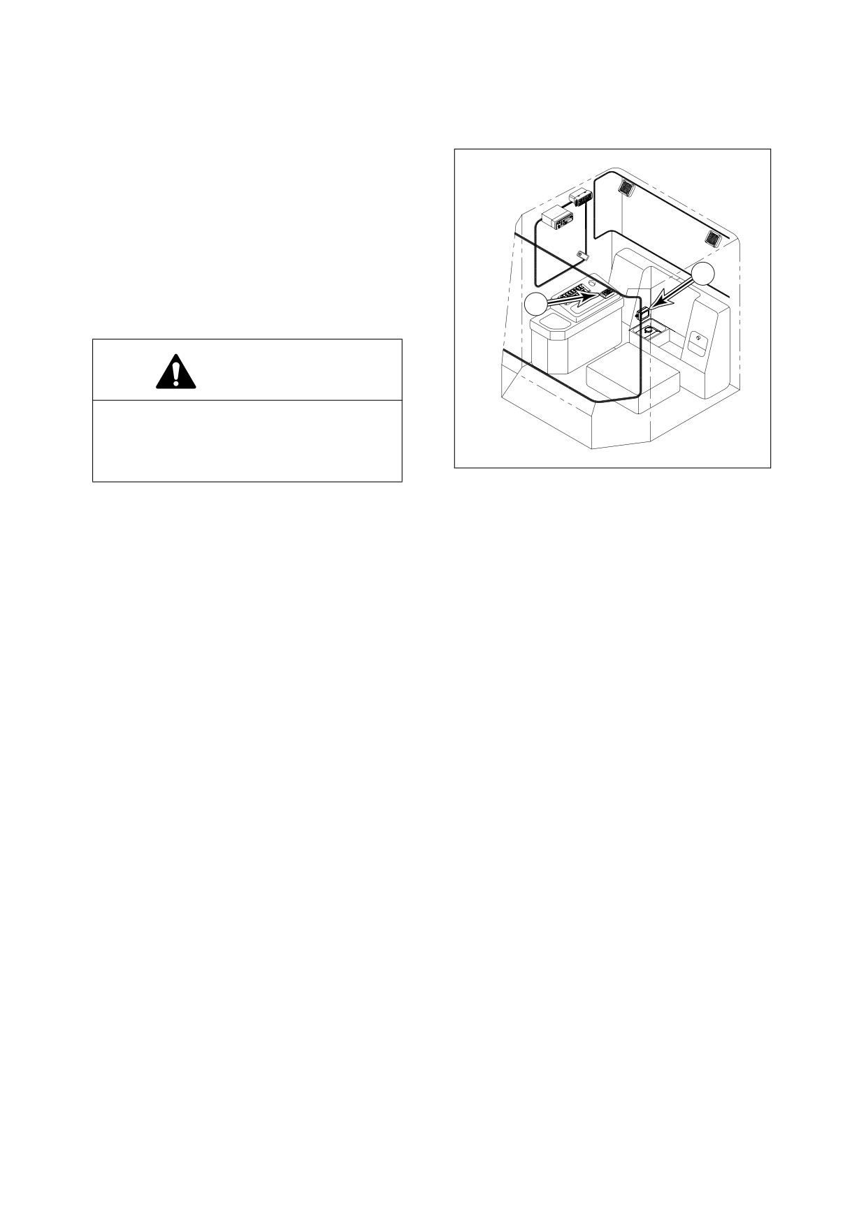
There are two fuse boxes inside the cab.
Fuse box one (1, Figure 103) is in the rear side
of right control stand. A usage diagram of fuses
is shown inside of fuse box. Spare fuses are
under the cover (10A - Qty. 1, 15A - Qty. 1, 20A
- Qty. 1).
2
Fuse box two (2, Figure 103) is just above the
1
windshield washer fluid tank.
WARNING!
If any fuse is blown, turn "OFF" the starter
switch and shut off the power supply.
Remedy the cause if needed and replace
AQO0160L
the fuse with a new one.
Figure 103
2-50 Operating Controls
022-00029AE Operation and Maintenance Manual
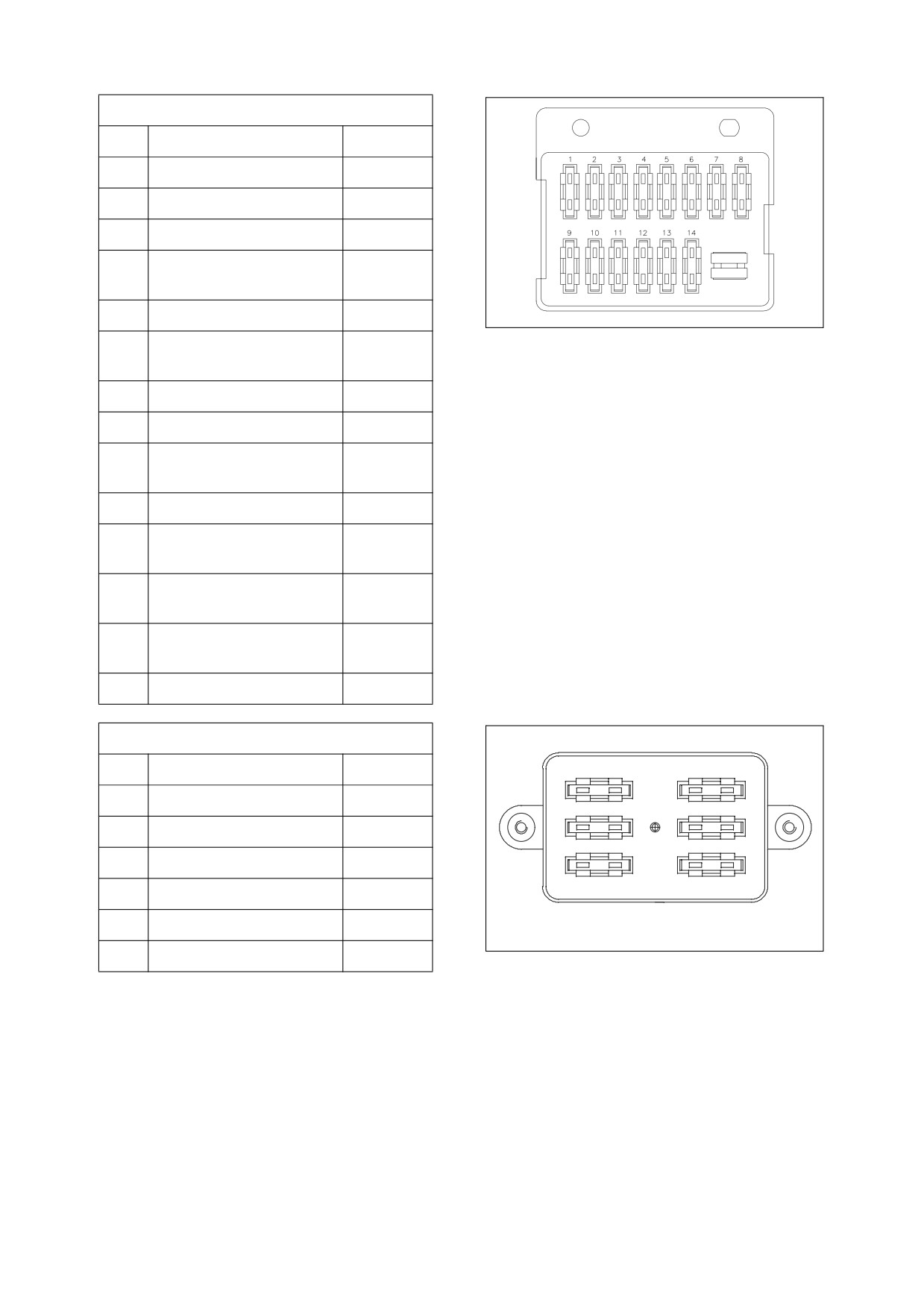
Fuse Box One
No.
Name
Capacity
1
Gauge Panel
15A
2
Transmission
15A
3
Front Wipers, Horn
15A
4
Parking Brake, Pilot
15A
Cutoff, Log Fork (Option)
5
Stop Light, Headlight
20A
HBOI380L
Figure 104 FUSE BOX ONE
6
Condenser Fan
15A
Engine Derating
7
Spare
15A
8
Air-conditioning, Heater
30A
9
Work Light (Front),
15A
Beacon (Option)
10
Work Light (Rear)
15A
11
Turn Signal Light, Hazard
15A
Light, Indicator Light
12
Stereo, Cab Light,
15A
Fuel Pump
13
Memory Backup,
10A
Pilot Buzzer
14
Starter Switch
10A
Fuse Box Two
No.
Name
Capacity
1
3
1
Cigar Lighter, Rear Wiper
15A
2
4
2
LIS (Option), Detente
10A
3
Position Light (Right)
10A
5
6
4
Position Light (Left)
10A
5
ECM
10A
HAAA3740
6
ECM
10A
Figure 105 FUSE BOX TWO
022-00029AE Operation and Maintenance Manual
Operating Controls 2-51
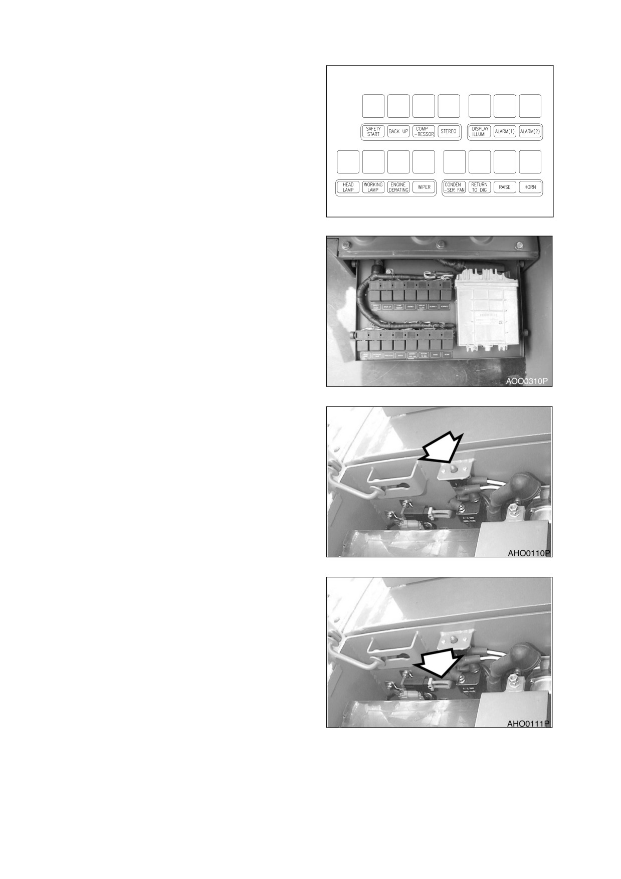
RELAY
The relays are in the electrical box under the
seat. If the problem is not solved after replacing
the fuse, check the function of the relay.
APO0210L
Figure 106
Figure 107
CIRCUIT BREAKER
A circuit breaker is next to the relay by the
batteries at back of unit under engine
compartment hood. When a short circuit or an
overload
occurs,
the
circuit
breaker
automatically cuts-off current, thus preventing
electrical wires from burning.
Figure 108
FUSIBLE LINK
A fusible link is in the battery box. If electric
power is not present at the "I" (ON) position of
the starter switch, check the fusible link first.
NOTE: If fuse wire is burnt off, replace
link.
Figure 109
2-52 Operating Controls
022-00029AE Operation and Maintenance Manual
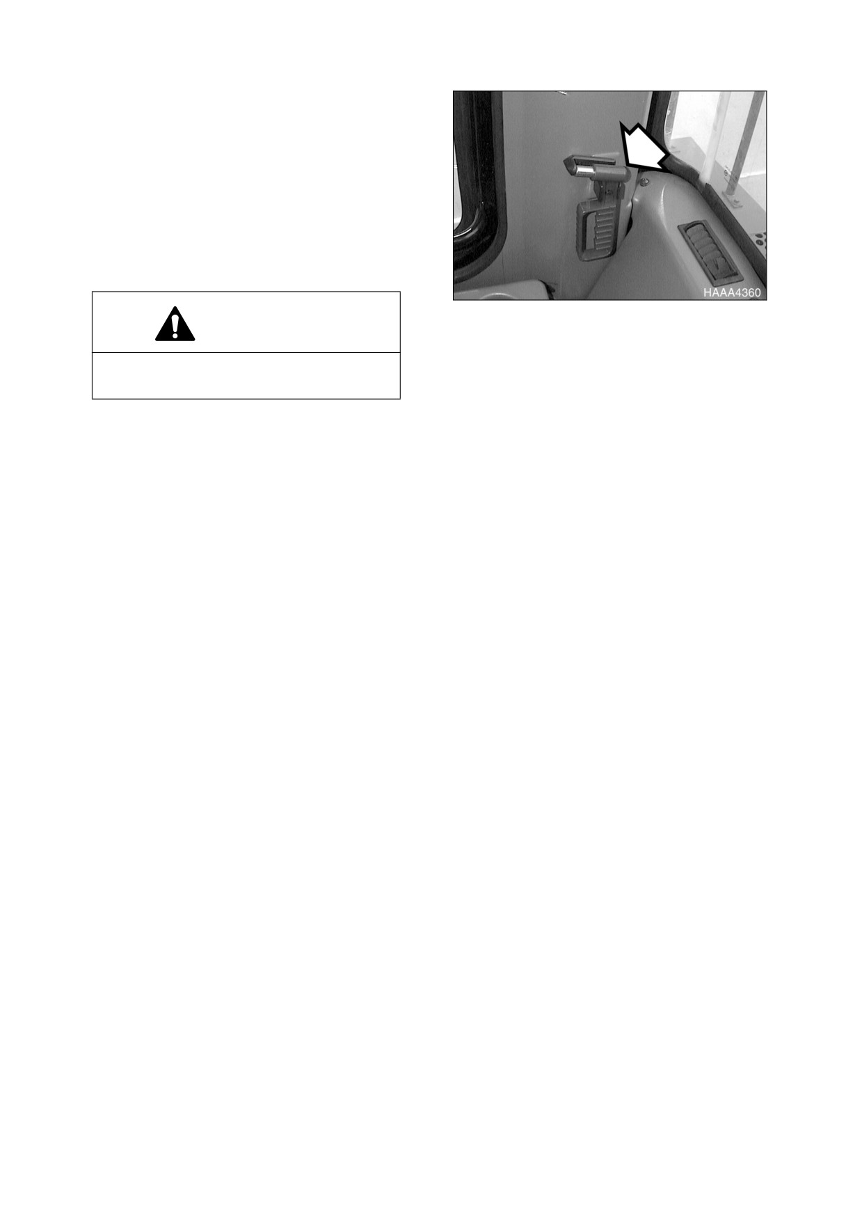
WINDOW GLASS
BREAKING TOOL
This loader is equipped with a glass breaking
tool. It is in the lower right side of the cab just
rear of the door. This tool can be used in case of
an emergency situation which requires the
breaking of glass to exit from the operator’s
cabin. Grip the handle firmly and use the sharp
point to break the glass.
Figure 110
WARNING!
Protect your eyes when breaking the
glass.
022-00029AE Operation and Maintenance Manual
Operating Controls 2-53

3OPERATION
WARNING!
Before operating any wheel loader, read and understand "Operating Controls" section of this
manual.
INSTRUMENT PANEL CONTROL FUNCTIONS
MONITORING SYSTEM
Monitoring system uses network circuits between control system and sensors installed at various machine
system locations to monitor selected conditions. This monitoring systems function is to continually inform
operator of machine’s condition. Displays and gauge readouts on instrument panel provide information
such as engine speed, engine coolant temperature, transmission oil pressure, and electrical charge status.
NEW MACHINE BREAK-IN PROCEDURES
All wheel loaders are inspected and adjusted before leaving the factory. However, it is required that the
operator follow these steps during initial break-in period. Failure to follow these steps may result in damage
to equipment or reduced performance.
1.
Make sure to check all fluid levels before starting and every 8 to 10 operating hours.
2.
Do all Daily maintenance and service checks.
3.
For first 50 operational hours, as shown by Hour Meter on control console, do not exceed 80% of
maximum rated engine speed.
4.
At end of first 50 operational hours, drain engine oil. Replace engine oil filter and engine oil.
022-00029AE Operation and Maintenance Manual
Operation 3-1
ENGINE START AND STOP
INSPECTION BEFORE STARTING ENGINE
WARNING!
If a flammable materials such as leaves, paper, etc. are allowed to accumulate on high
temperature components, such as the engine muffler and turbo, a fire may occur. Fuel, lubricant
and hydraulic oil leaks, may cause a fire. If there is anything wrong, perform the appropriate
corrective action.
Before starting engine, inspect the following items;
1.
Electric system - Check for damaged electric cables, and loose or missing connectors.
2.
Fuel system - Drain water and sediment from fuel tank and water separator.
3.
Hydraulic system - Check for hydraulic oil leaks, damaged tubing and hoses, and interference points
of components.
4.
Lubrication - Perform all daily and periodic maintenance services. Perform services according to
reading shown on hour meter.
5.
Safety - Perform a machine walk-around. Make sure that no one is under the machine or performing
any maintenance on it, before starting engine.
6.
After starting machine - Check that all operational controls and components, are in proper operating
condition, and are functioning correctly. Stop operation and correct any malfunction before continuing
work.
ENGINE START
1.
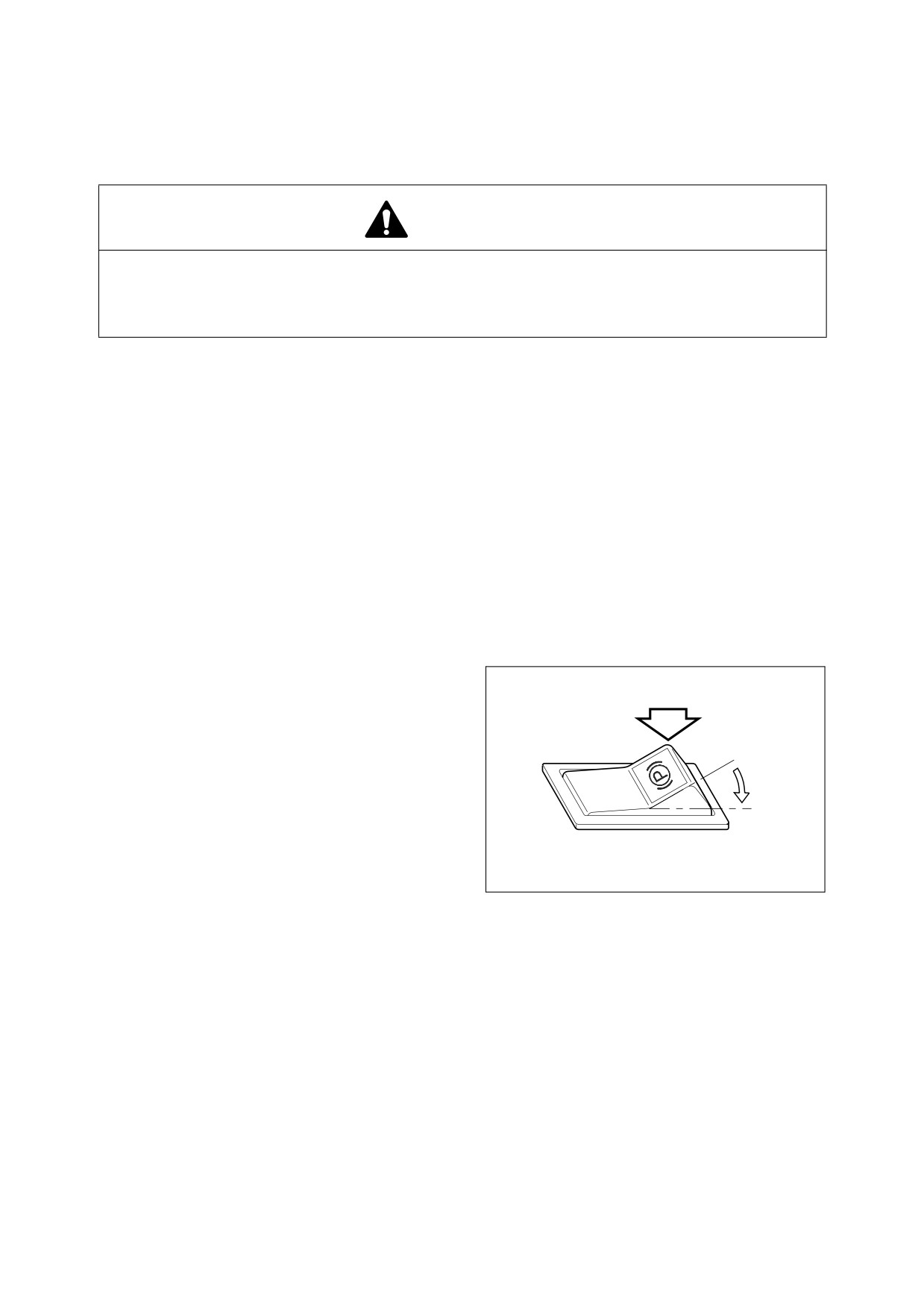
Set parking brake switch to the "I"
(ENGAGED) position. This will ensure that
the parking brake is "APPLIED."
O
I
HAOP042L
Figure 1
3-2 Operation
022-00029AE Operation and Maintenance Manual
2.
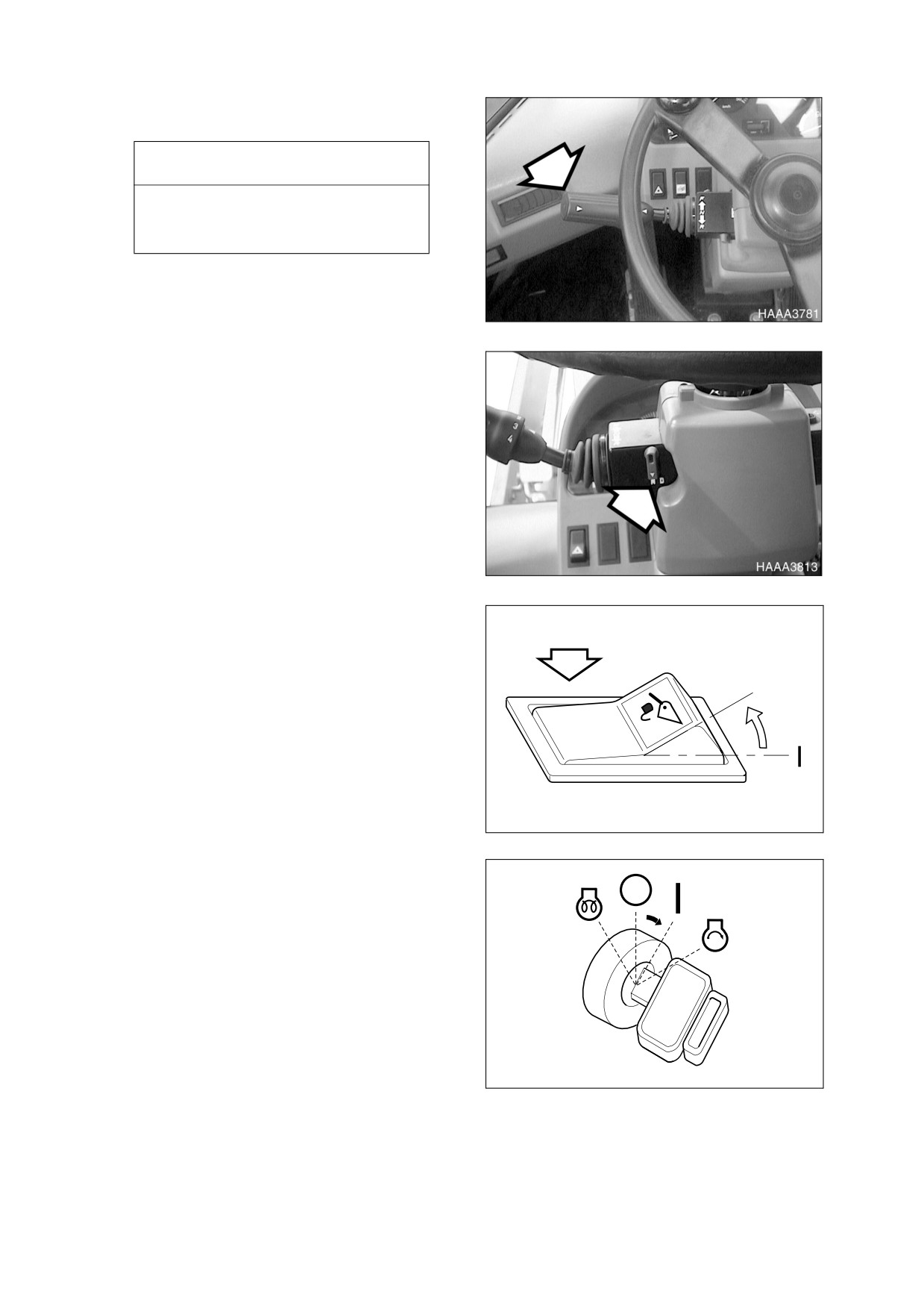
Move all control levers to "NEUTRAL"
position.
IMPORTANT
If transmission lever is not in
"NEUTRAL" position, engine will not
start.
Figure 2
3.
Make sure transmission neutral lock is in
the "N" (NEUTRAL LOCK) position.
Figure 3
4.
Set pilot cutoff switch to "O"
(LOCK)
position. This will "LOCK" pilot control
valve lever (joystick).
O
HBOI111L
Figure 4
5.
Rotate starter key to "I" (ON) position. All
indicator lights should turn "ON."
NOTE: The engine has an Electronic
Control Module
(ECM) that
controls the preheat system.
This system eliminates the
need for a cold weather startup
procedure. Due to this system
the preheat position of the
starter switch is not used.
HAOB320L
Figure 5
022-00029AE Operation and Maintenance Manual
Operation 3-3
6.
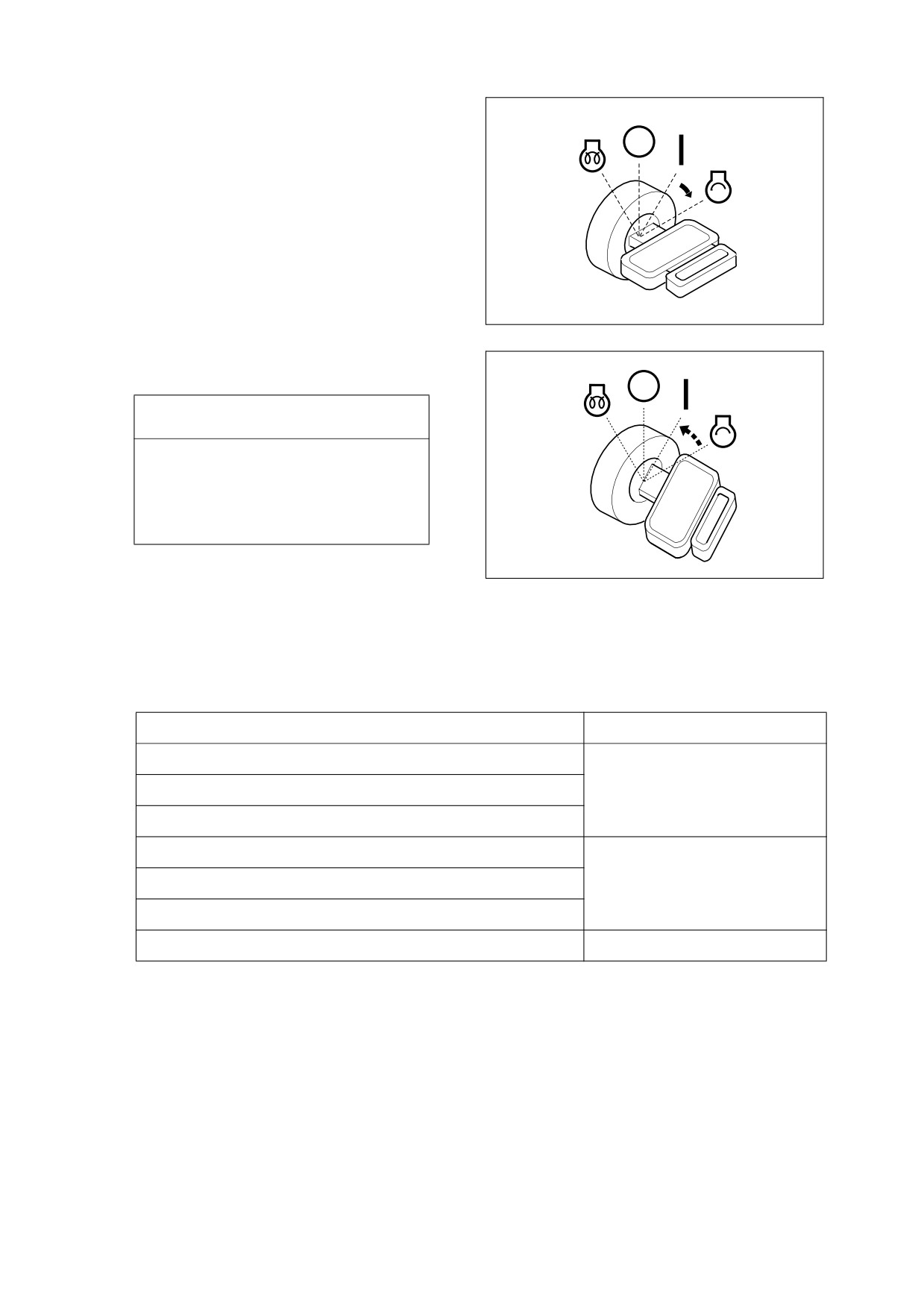
Rotate starter key to "START" position.
Starter motor should crank immediately,
and engine should start within a few
seconds.
HAOB350L
Figure 6
7.
Release starter key when engine starts.
Key will return to "I" (ON) position.
IMPORTANT
If
engine does not start after
approximately
15
seconds of
cranking, release starter key. Wait 5
minutes for starter motor to cool
down. Repeat step 6.
HAOB360L
Figure 7
8.
After engine starts, check all indicator lights and gauges to be certain that all engine systems (oil
pressure, oil temperature, coolant temperature, etc.) are in normal operating range. If any engine
system is not normal, turn starter key to "OFF" position.
Instrument Panel Light or Gauge
Indicator Reading
Fuel gauge
Engine coolant temperature gauge
White Range
Transmission oil temperature gauge
Engine oil pressure warning light
Charging warning light
Off
Brake oil pressure warning light
Parking brake light
On
NOTE: Parking brake indicator light turns "ON" or "OFF" according to parking brake operation
despite engine starting.
9.
Perform “Hydraulic System Warm-up” on page 3-9.
10. Check color of exhaust smoke
•
No color or light blue - Engine is running in good condition.
3-4 Operation
022-00029AE Operation and Maintenance Manual
•
Black - Incomplete combustion. Check cause.
•
White or dark blue - Engine is burning engine oil. Check cause.
11. Check for usual engine vibration and noises. If any are heard or felt, investigate cause.
NOTE: If engine coolant temperature gauge shows red while running, take the following action;
Discontinue work and allow engine to run at "LOW IDLE." Open engine compartment
cover for good ventilation. Once engine temperature gauge returns to the green zone, shut
down engine. After engine has cooled, check coolant level, look for leaks, clogged or dirty
radiator fins (radiator core), and fan belt tension.
022-00029AE Operation and Maintenance Manual
Operation 3-5
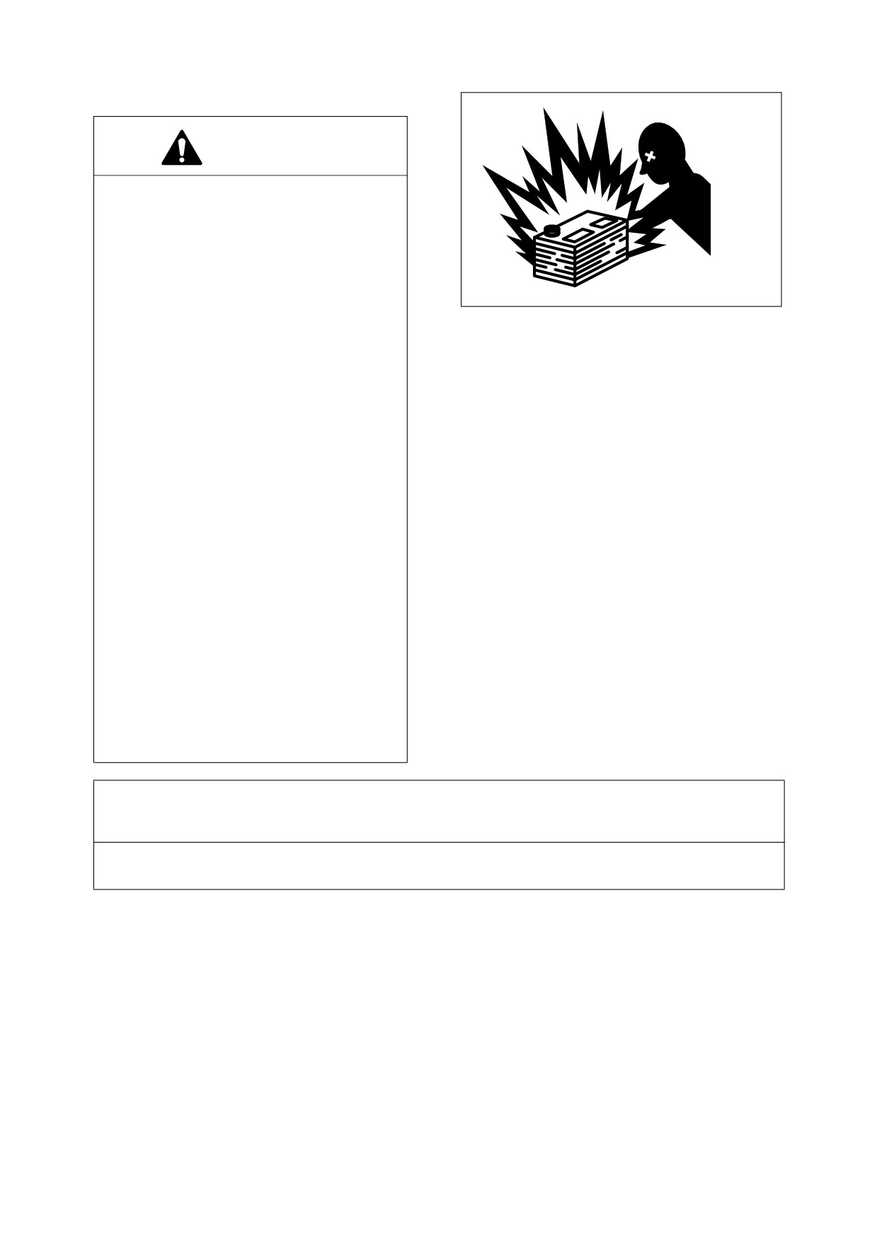
STARTING WITH AUXILIARY BATTERIES
WARNING!
1.
An explosive gas is produced while
batteries are in use or being charged.
Keep flames or sparks away from the
battery area.
2.
Charge batteries in a well-ventilated
area.
HAOA440L
3.
Always wear eye protection when
Figure 8
starting a machine with jumper
cables.
4.
Improper jump starting procedures
can cause an explosion resulting in
personal injury.
5.
Jump start vehicles on dry ground or
concrete. Do not jump start the
machine on a steel floor, because the
floor is always grounded.
6.
When starting from another machine,
make sure the machines do not
touch.
7.
Always connect the auxiliary battery
positive
(+) terminal too depleted
battery positive
(+) terminal first.
Then connect
auxiliary battery
negative (-) terminal to the frame of
the depleted battery machine
second.
8.
Connect positive cable first when
installing cables and disconnect the
negative cable first when removing.
IMPORTANT
The machine has a 24V (-) negative ground electrical system. Use the same capacity 24V booster
batteries when jump starting engine.
If the batteries are drained during starting procedures, jump start engine using auxiliary or booster
batteries according to the following procedure;
3-6 Operation
022-00029AE Operation and Maintenance Manual
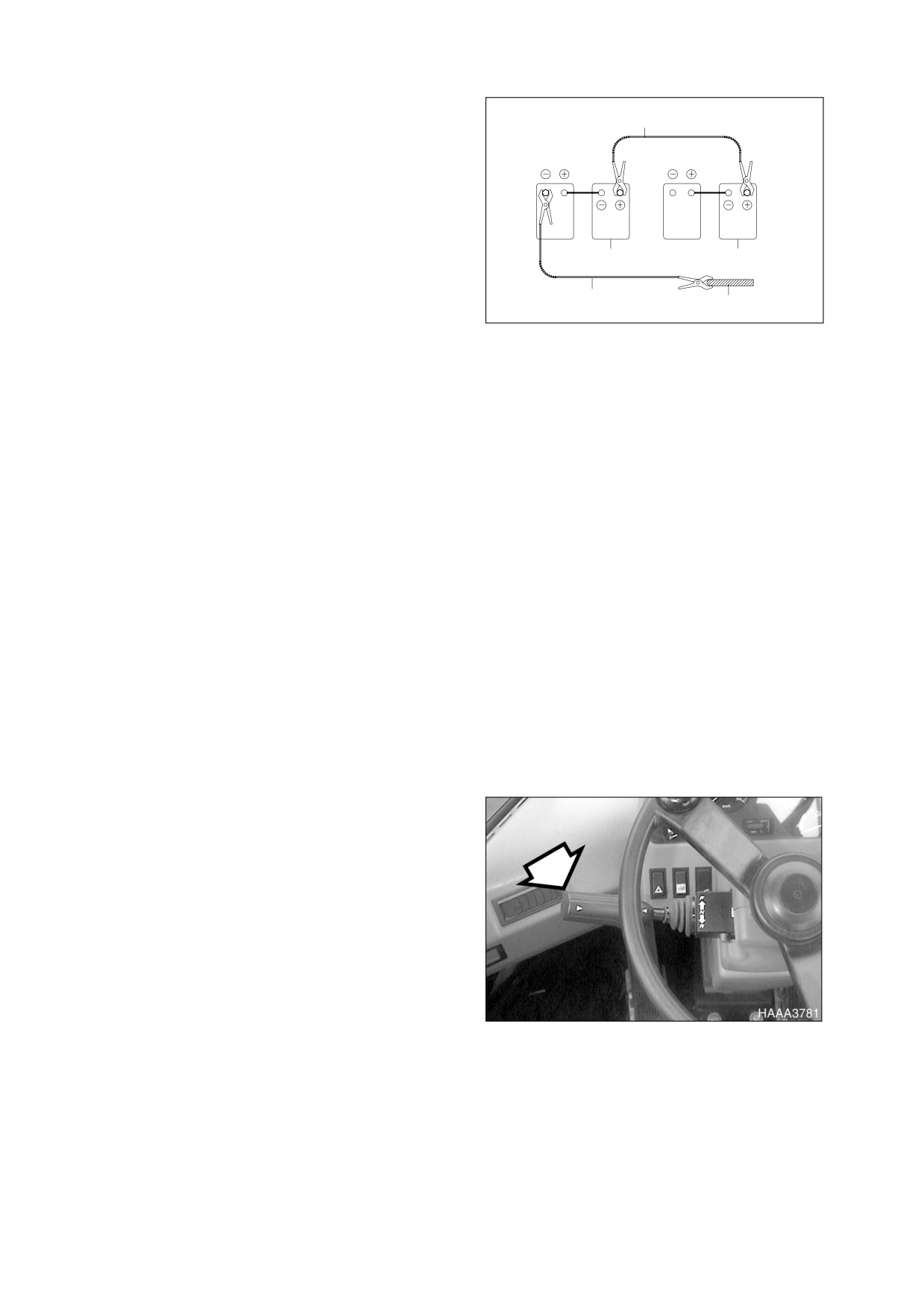
Connecting the Booster Batteries
1
1.
Stop the engine of the machine on which
RED
booster batteries are mounted.
2.
Connect one end of red cable (1, Figure 9)
to the positive (+) terminal of the machine
batteries, and the other end to the positive
(+) terminal of the booster batteries.
3.
Connect one end of black cable (2, Figure
3
4
BLACK
9) to the negative
(-) terminal of the
booster batteries, and then make ground
2
5
connection to the upper frame of the
ARO0440L
machine to be started with the other end of
Figure 9
black (-) cable (2, Figure 9). In the last
connection to upper frame, be sure to
connect the cable end as far away from
the machine batteries as possible. DO
NOT CONNECT DIRECTLY TO THE
NEGATIVE BATTERY TERMINAL.
4.
Start the engine
Disconnecting the Booster Batteries
1.
Disconnect black negative
(-) cable
(2,
Figure 9) from the machine frame first.
2.
Disconnect the other end of black negative
(-) cable
(1, Figure
9) from the booster
batteries.
3.
Disconnect red positive
(+) cable
(1,
Figure 9) from the booster batteries.
4.
Disconnect red positive
(+) cable
(1,
Figure 9) from the machine batteries.
ENGINE STOP
1.
Move transmission lever to "NEUTRAL"
position.
Figure 10
022-00029AE Operation and Maintenance Manual
Operation 3-7
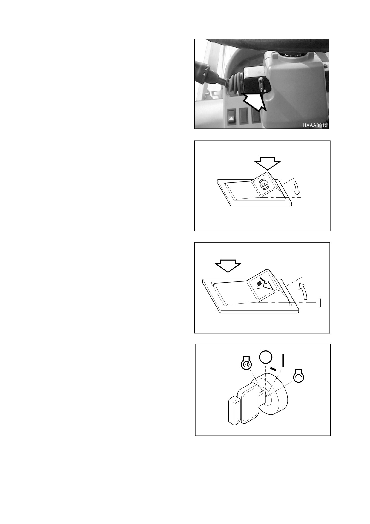
2.
Make sure transmission neutral lock is in
the "N" (NEUTRAL LOCK) position.
Figure 11
3.
Set parking brake switch to the "I"
(APPLIED) position. This will ensure that
the parking brake is "APPLIED."
O
I
HAOP042L
Figure 12
4.
Set bucket on ground.
5.
Put pilot cutoff switch to "O"
(LOCK)
position. This will "LOCK" pilot control
valve lever (joystick).
O
6.
Allow engine to idle for 3 - 5 minutes to
cool down. Stopping a turbocharged
engine without a cool down period can
seriously damage turbocharger.
HBOI111L
Figure 13
7.
Rotate starter key to "O" (OFF) position.
Remove key.
HAOC342L
Figure 14
3-8 Operation
022-00029AE Operation and Maintenance Manual
HYDRAULIC SYSTEM WARM-UP
1.
Correct operating temperature of hydraulic oil is 50° - 80°C (120° - 175°F). Make sure to follow
procedures listed below for hydraulic fluid warm-up.
2.
Run engine at idle (no load) for 5 minutes.
3.
Run engine for approximately 5 minutes at middle of speed range, without a load.
4.
Cycle bucket until bucket cylinder bottoms out (extended and retracted) without a load to circulate the
oil through the system. Do this for 5 minutes.
NOTE: Do not allow cylinders to pass hydraulic oil over relief valve for more than twenty seconds
at a time.
5.
Cycle boom and bucket about five times without a load to circulate oil through system.
HYDRAULIC SYSTEM WARM-UP - COLD WEATHER
1.
Follow Steps 1 through 3 in Hydraulic System Warm-up.
2.
Do not operate machine at full speed until system has fully warmed up.
3.
If working speeds continue to be slow, repeat initial hydraulic warm-up procedures again. If repeating
warm-up procedures does not improve working speeds, continue to operate, but use extreme caution
because machine function may be erratic.
MACHINE TRAVEL
WARNING!
If vehicle is moved while parking brake is engaged, serious damage to parking brake disc will
result.
Select a transmission gear that is appropriate for top speed that will be traveled. Choosing a
gear that is too high will reduce acceleration and will unnecessarily heat transmission converter
oil.
Never place transmission in "NEUTRAL" when going down a hill. Over speeding transmission
can damage transmission gears.
Never change direction of vehicle travel at high speed. Serious damage to transmission will
result.
022-00029AE Operation and Maintenance Manual
Operation 3-9
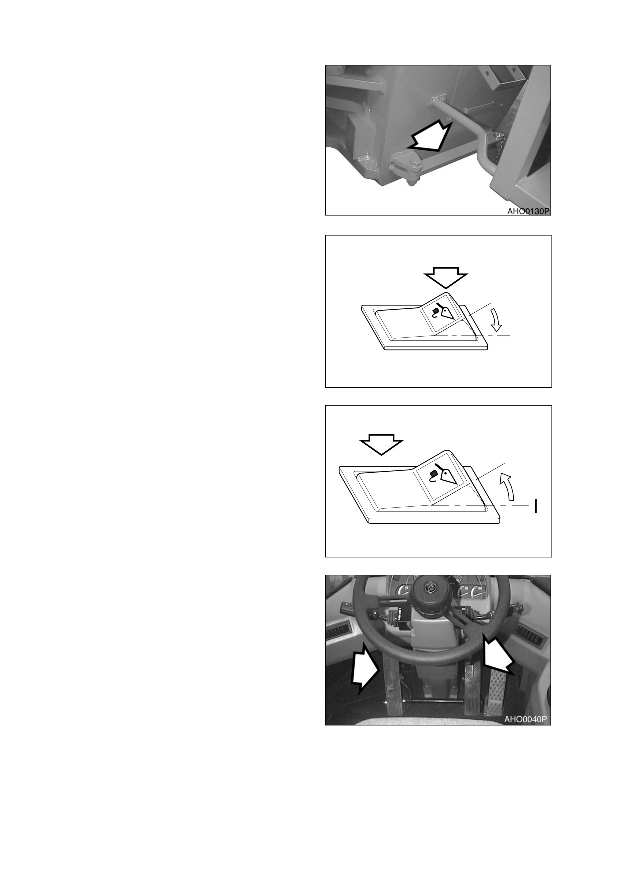
1.
Unlatch frame lock plate between front and
rear frames before traveling. Secure lock
plate to rear frame (Figure 15).
Figure 15
2.
Set pilot cutoff switch to "I" (UNLOCKED)
position. Raise bucket to a height of 400
mm (16 in) above the ground. Tilt bucket
completely back.
O
I
HBOI110L
Figure 16
3.
Set pilot cutoff switch to "O" (LOCKED)
position. This will prevent boom and bucket
from accidentally moving during travel, as
a result of accidentally touching pilot
control valve lever (joystick).
O
HBOI111L
Figure 17
4.
Press brake pedal.
Figure 18
3-10 Operation
022-00029AE Operation and Maintenance Manual
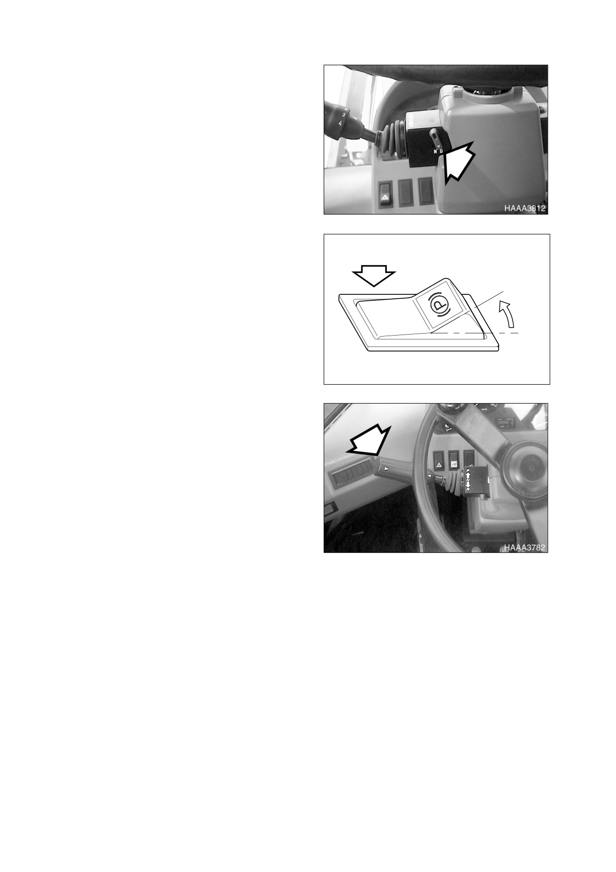
5.
Set transmission neutral lock is in the "D"
(DRIVE) position.
Figure 19
6.
Set parking brake switch to the "O"
(RELEASE) position. This will "RELEASE"
the parking brake.
O
I
HAOP043L
Figure 20
7.
Place transmission lever in desired gear.
Shift gears one by one. Do not skip from
1st to 3rd, for example.
8.
Shift transmission lever to "FORWARD"
position.
Figure 21
022-00029AE Operation and Maintenance Manual
Operation 3-11
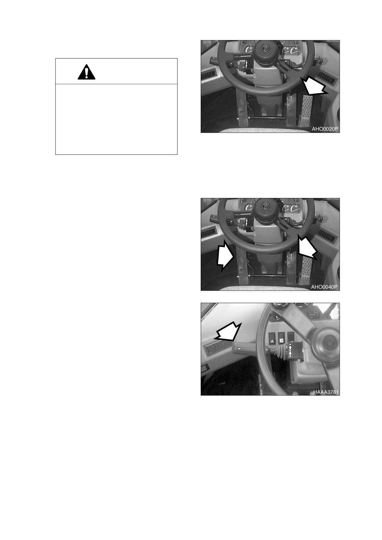
9.
Release the brake pedal while slowly
pressing the accelerator pedal.
WARNING!
When traveling at high speed or on a
steep hill, do not make sharp
changes in direction. This could
cause vehicle to overturn.
When traveling or changing
direction, always look carefully to be
certain that no one is in path of
Figure 22
vehicle.
MACHINE SHUTDOWN
1.
Ease off throttle and apply travel brakes.
Figure 23
2.
Put transmission lever in "NEUTRAL."
Figure 24
3-12 Operation
022-00029AE Operation and Maintenance Manual
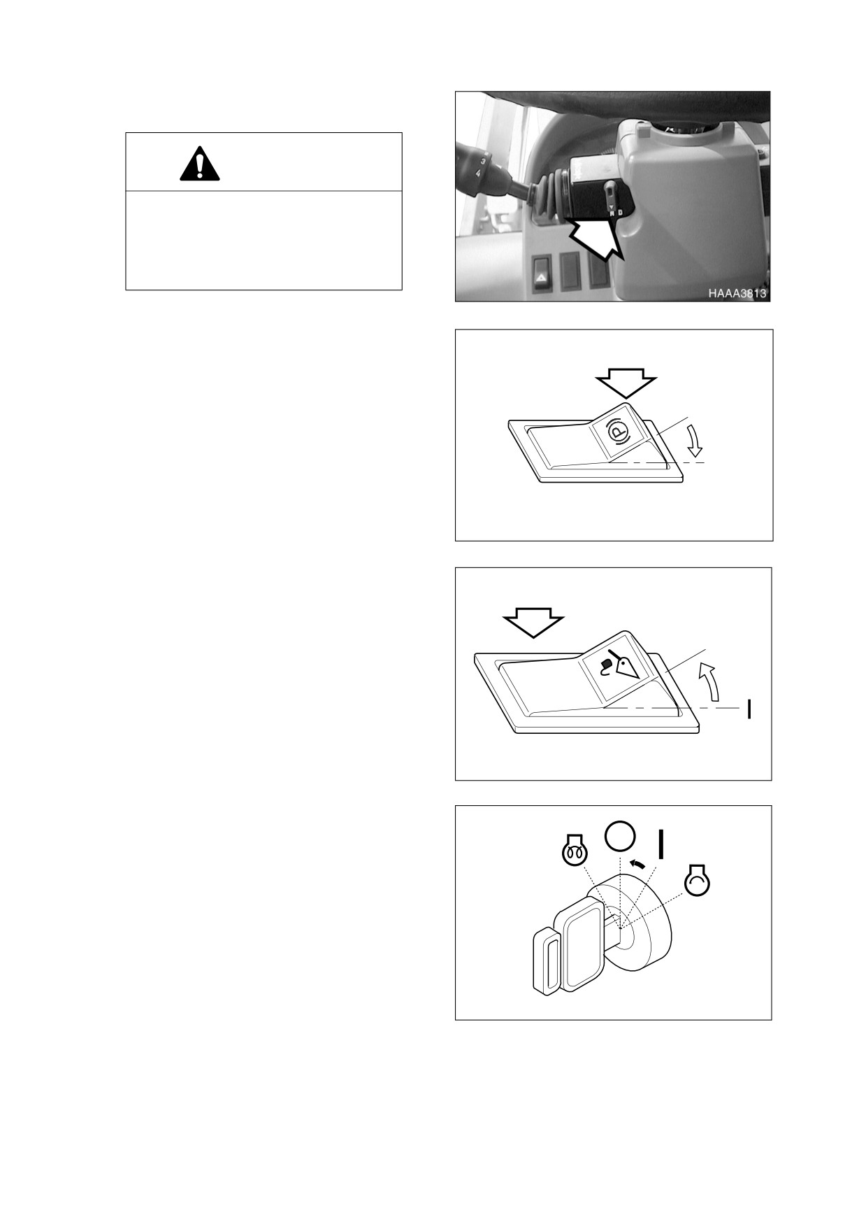
3.
Set transmission neutral lock is in the "N"
(NEUTRAL LOCK) position.
CAUTION!
"LOCK" transmission lever. When
ever machine is parked, "LOCK"
transmission lever in "NEUTRAL" to
prevent
accidental
machine
movement.
Figure 25
4.
Set parking brake switch to the "I"
(APPLIED) position. This will ensure that
the parking brake is "APPLIED."
O
I
HAOP042L
Figure 26
5.
Set bucket on ground.
6.
Select pilot cutoff switch to "O" (LOCKED)
position. This will lock pilot control valve
lever (joystick).
O
7.
Allow engine to idle for 3 - 5 minutes to
cool down. Stopping a turbocharged
engine without a cool down period can
seriously damage turbocharger.
HBOI111L
Figure 27
8.
Rotate starter key to "O" (OFF) position.
Remove key.
HAOC342L
Figure 28
022-00029AE Operation and Maintenance Manual
Operation 3-13
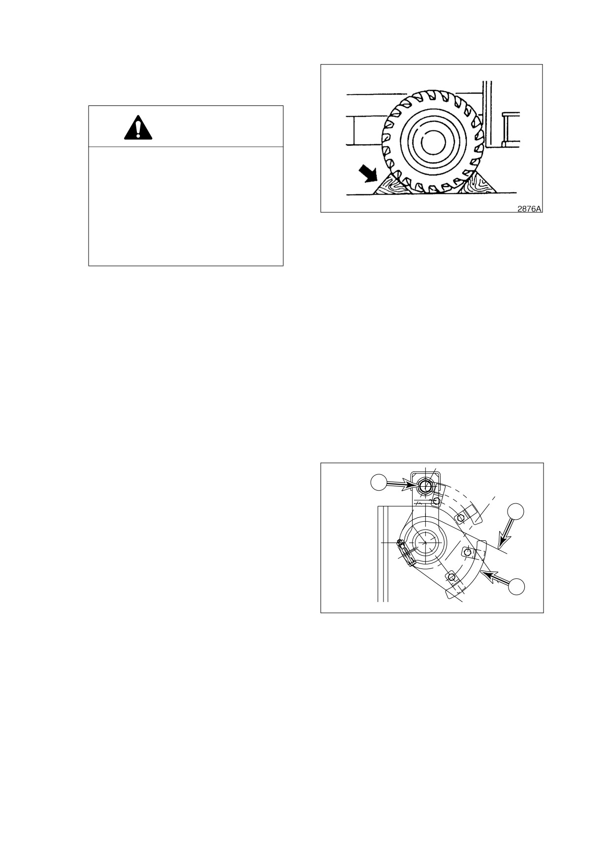
9.
If machine is parked on a slope, install
wheel chocks in front of and behind vehicle
wheels.
WARNING!
Always secure machine with wheel
chocks when parked on a slope.
Leaving machine in gear will provide
no braking
effect
because
transmission clutch is hydraulically
operated. When engine is turned
Figure 29
"OFF," there is no hydraulic pressure
in transmission and clutch is not
engaged.
ADDITIONAL BRAKING
Machine hydraulic system can supply additional braking force during travel. To accomplish this, move pilot
control valve lever (joystick) to crowd position and hold it there. Hydraulic pump will be driven to supply
output at maximum pressure (relief pressure). Energy expended to drive pump, will slow engine speed.
Additional braking, along with proper gear selection, can be used to slow a vehicle that is being driven
down an incline.
BOOM RAISE KICKOUT
Placing pilot control valve lever
(joystick) in
"Boom Raise Detent" position will lock lever
2
(joystick) in raise boom position. Boom will raise
until trip plate (1, Figure 30) makes contact with
bucket height limit switch (2). When limit switch
3
is tripped, boom will stop raising and lever
(joystick) will automatically be returned to
"NEUTRAL" position. Trip plate can be adjusted
to control maximum height that boom can be
raised.
1
HBOI441L
Figure 30
3-14 Operation
022-00029AE Operation and Maintenance Manual
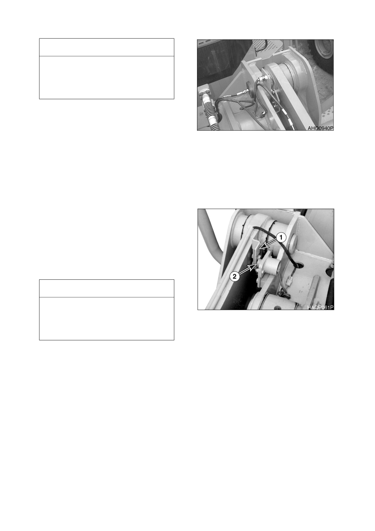
IMPORTANT
Trip plate (1, Figure 30) must always be set
to contact limit switch (2) before boom
cylinders reach maximum extension.
Maximum extension causes pump to force
fluid over relief valve.
To raise boom to maximum height, past preset
height, hold pilot control valve lever (joystick) in
"RAISE" or "HOLD RAISE" position until boom
has reached maximum height. Then remove
Figure 31
your hand from lever. Lever will automatically
return to "NEUTRAL" position. This prevents
hydraulic pump from working against relief valve
(maximum pressure).
BOOM LOWER KICKOUT (OPTION)
Placing bucket lever in
“L” position will lock
control lever in lower boom position. Boom will
move downward until trip plate (1, Figure 32)
makes contact with bucket lower limit switch (2).
When limit switch is tripped, boom will stop
lowering and bucket lever will automatically be
returned to “NEUTRAL” position. Trip plate can
be adjusted to control maximum height that
boom can be lowered.
IMPORTANT
Trip plate must always be set to contact
limit switch before boom cylinders reach
Figure 32
maximum extension. Maximum extension
causes pump to force fluid over relief
valve.
022-00029AE Operation and Maintenance Manual
Operation 3-15
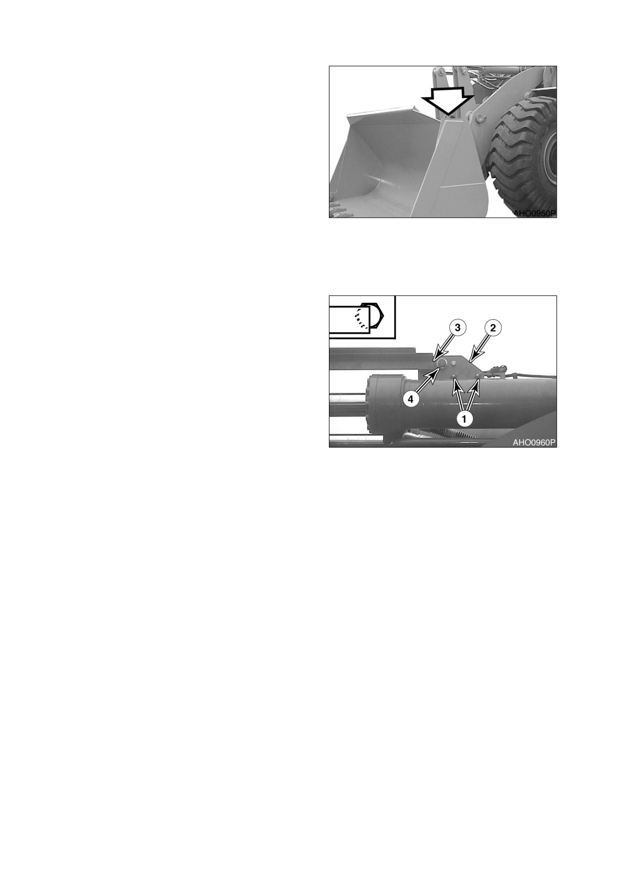
BUCKET ANGLE
INDICATOR
Upper right side of bucket includes a bracket
that indicates angle of bottom of bucket. Top of
bracket is parallel with bottom of bucket. If
bottom of bucket is not visible, top of bracket will
be visible.
ADJUSTMENT OF
Figure 33
BUCKET POSITION
SWITCH
When bucket lever is held in crowd detent
position, after bucket has been dumped, bucket
will pivot toward crowd position. Once full crowd
position has been reached, bucket lever will
automatically return to “NEUTRAL” position. If
bucket is lowered after lever returns to
“NEUTRAL,” bucket will automatically position
itself to be in a preselected digging position
(usually flat). To adjust bucket to desired
preselected digging position, perform the
following steps.
1.
Operate controls to place bucket on
ground and in desired digging position
Figure 34
(usually flat). Return bucket lever to its
“NEUTRAL” position.
2.
Turn “OFF” engine.
3.
Loosen bolts (1, Figure 34) on bracket (2).
4.
Position bracket (2, Figure 34) so that end of arm (3) is aligned with center of magnetic switch (4).
5.
Tighten bolts (4, Figure 34).
6.
Start engine. Raise boom, dump bucket, then move bucket lever into crowd detent position. Now
lower boom and check to see that bucket has stopped at required position. A small readjustment of
bracket (2, Figure 34) may be necessary.
3-16 Operation
022-00029AE Operation and Maintenance Manual
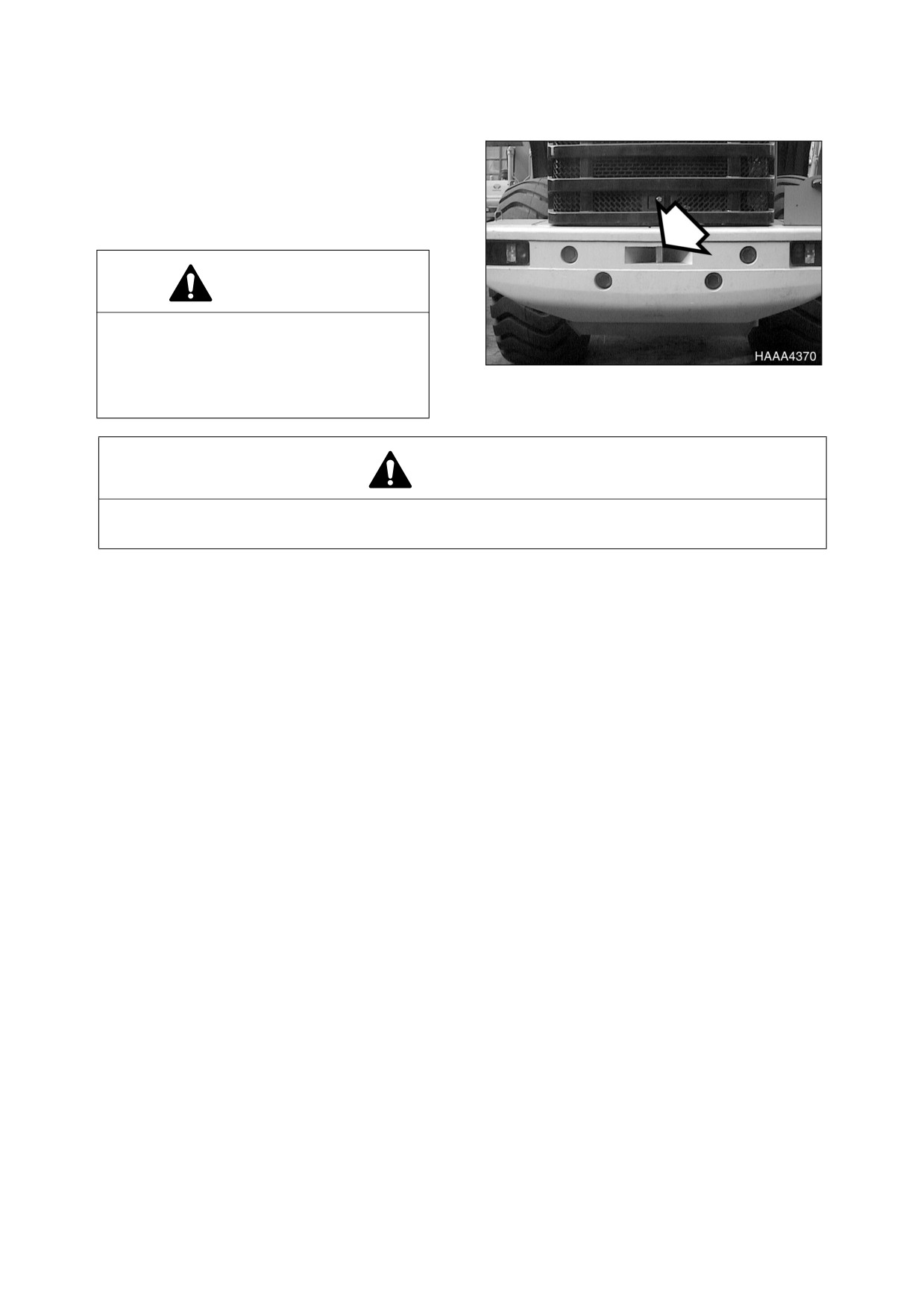
TOWING MACHINE
When necessary to tow another vehicle, the tow
rope must be tied to the towing pin on the
counterweight at the rear of vehicle.
NOTE: The loader must be used for
towing only in an emergency.
WARNING!
Do not tow machine at a speed over 10
kph (6 MPH) and do not tow machine
farther than
10 Km (6 miles). This will
prevent damage to machine transmission
Figure 35
that would result from lack of lubrication.
WARNING!
When towing another vehicle on a public road, take necessary measures to let other vehicles
and people know that you are towing another vehicle. Use a flag, rotating light, or hazard light.
NOTE: There are several requirements you must abide by when towing another vehicle. Learn the
regulations and rules about towing another vehicle and observe them.
If the loader is being towed by another vehicle and the engine will not start, remove the front and rear drive
shafts; otherwise the transmission will rotate without being properly lubricated, causing seizure. Before
removing them, apply the parking brakes and block the wheels securely.
If the engine can be started and the steering wheel and brakes function normally, have someone get on the
loader you are going to tow for steering it.
Before you tow a vehicle make sure you have checked the following:
•
Check the weights of your loader and the vehicle to be towed and make sure you loader has
sufficient braking capacity to stop the towed load.
•
Check if the vehicle to be towed can be braked and steered. If not, do not allow anyone to ride
on the towed vehicle.
•
Check the tow rope or tow bar for damage and make sure it has sufficient strength for the work.
•
When necessary to descend a gradient, another towing vehicle must be used in the rear to
retard.
When towing make sure you are doing the following:
•
Start slowly. A sudden start can lead to a broken tow rope.
•
The tow line must be in line with the centerline of both your loader and the vehicle to be towed.
•
If you use any other towing device, refer to the Instruction Manual supplied with the towing
device.
•
If it is difficult to tow the loader, transport it by a trailer truck to your nearest repair shop.
•
In addition to the above measures, release the parking brake if the engine will not start or the
hydraulic pumps are defective.
022-00029AE Operation and Maintenance Manual
Operation 3-17
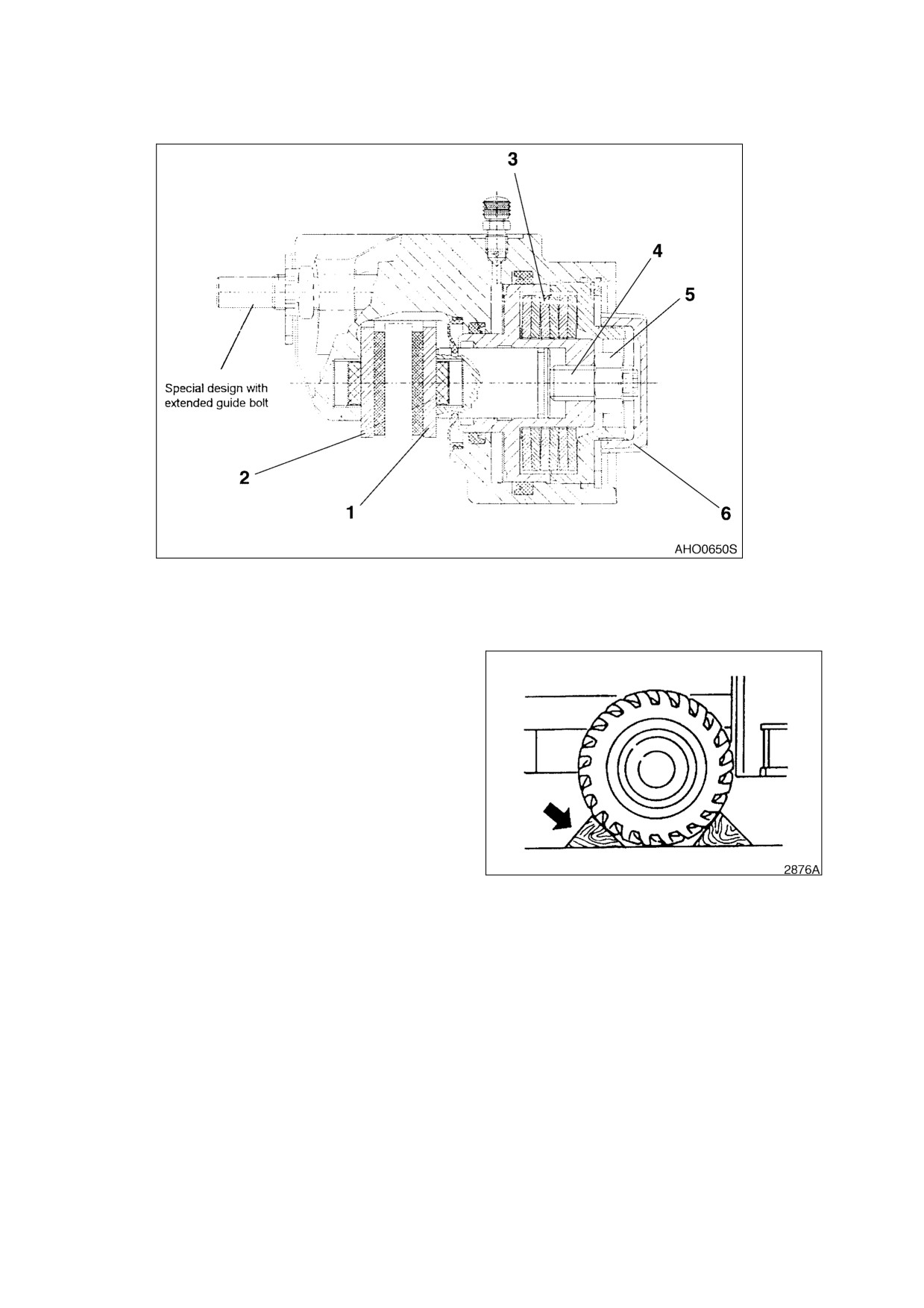
EMERGENCY RELEASE OF THE PARKING BRAKE
Figure 36
If the parking brake cannot be released by normal hydraulic system pressure, or if the engine will not start,
it must be manually released before towing can take place.
1.
Before releasing parking brake make sure
that wheels have wheel chocks placed in
front of and behind them, to prevent
machine from moving when parking brake
is released.
Figure 37
3-18 Operation
022-00029AE Operation and Maintenance Manual
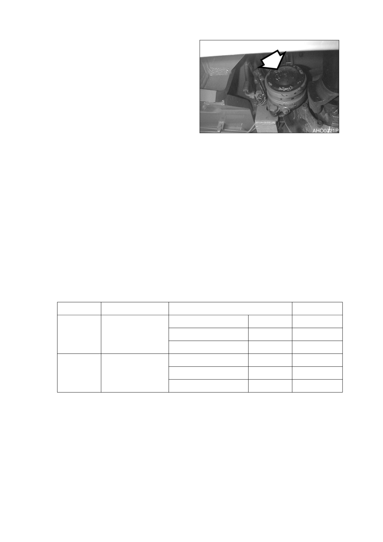
2.
Release the screw cap (6, Figure 36) and
unscrew.
3.
Release the lock nut (5, Figure 36) and
turn the adjusting screw
(4) counter-
clockwise until the brake disc is free.
4.
Install lock nut (5, Figure 36) and screw
cap (6) and tighten both as far as possible.
This will protect the parking brake
assembly from dirt.
NOTE: Now, the vehicle does not have
any brake function. The vehicle
must be secured against
Figure 38
moving away with proper
means. Before putting the
vehicle into operation again, the
brake has to be adjusted
according
to
adjusting
regulations.
ADJUSTING REGULATIONS
During this adjusting process, the parking brake must be released, i.e. the bank of cup springs (3, Figure
36) must be completely pre-tensioned.
1.
Park vehicle on an even surface and place wheel chocks in front of and behind tires. Only then
release the parking brake.
2.
Release the screw cap (6, Figure 36) and unscrew.
3.
Release the lock nut (5, Figure 36) (size 24 or 30) and turn the adjusting screw (4) with socket
wrench (size 8 or 10) clockwise until the two brake pads (1) and (2) make contact with the brake disk.
4.
Turn the adjusting screw (4, Figure 36) counter-clockwise and set the clearance specified in the
following table.
Type
Adjusting Screw
Clearance (mm)
Revolutions
min.
0.5
1/4
Small
M 16 (size 8)
Rated clearance
1.0
1/2
max
1.5
3/4
min.
1.0
2/5
Large
M 20 (size 10)
Rated clearance
2.0
4/5
max
3.0
1 1/5
5.
Hold the adjusting screw (4, Figure 36) in position with the hexagonal socket wrench and lock with
the lock nut (5).
6.
Mount the screw cap (6, Figure 36) and tighten as far as possible manually.
7.
Actuate the brake valve several times and check the braking efficiency of the parking brake on slope.
022-00029AE Operation and Maintenance Manual
Operation 3-19
IF ENGINE STALLS WHILE TRAVELING
BRAKE SYSTEM: The brakes can be applied approximately 9 times by pressing the brake pedal due to the
oil pressure stored in the accumulator after engine is turned "OFF" If the engine stalls while traveling,
move to an out of traffic area and park. Do not pump the brake pedal at this time; otherwise the brake
oil pressure will be used up, thus causing the brakes to fail.
ALLOWABLE WATER DEPTH
The water depth is an important factor to take into consideration when the loader is working in swampy
areas. Do not enter water whose depth exceeds the loader's minimum ground clearance height or is high
enough to wet the bottom of the axle housing. As a rule of thumb, the allowable water depth is about 400
mm (16 in). This means that the loader should not be used in a river.
Observe the following conditions:
1.
Check the water depth in advance when crossing across a river.
2.
Use the same precautions before crossing across a swampy area.
3.
Do not enter rivers whose river bed is steep or has a rapid flow.
CAUTION!
Avoid use of the loader in salt water. Salt water will cause the development of rust which will
shorten the life of the loader.
3-20 Operation
022-00029AE Operation and Maintenance Manual
4INSPECTION, MAINTENANCE AND
ADJUSTMENT
PREVENTIVE MAINTENANCE
Periodic checks and replacement of oil, grease, filters, etc. must be made at specific intervals, to keep
machine in good working condition. The following pages describe items to be checked, lubricants to be
used, and time interval between each check.
NOTE: Time interval between each service check may need to be shortened if machine is
operating in severe atmospheric conditions. Machines working in extremely hot or dusty
conditions will require more frequent service checks. Total hours of machine operation are
determined by hour meter that is on the front instrument panel.
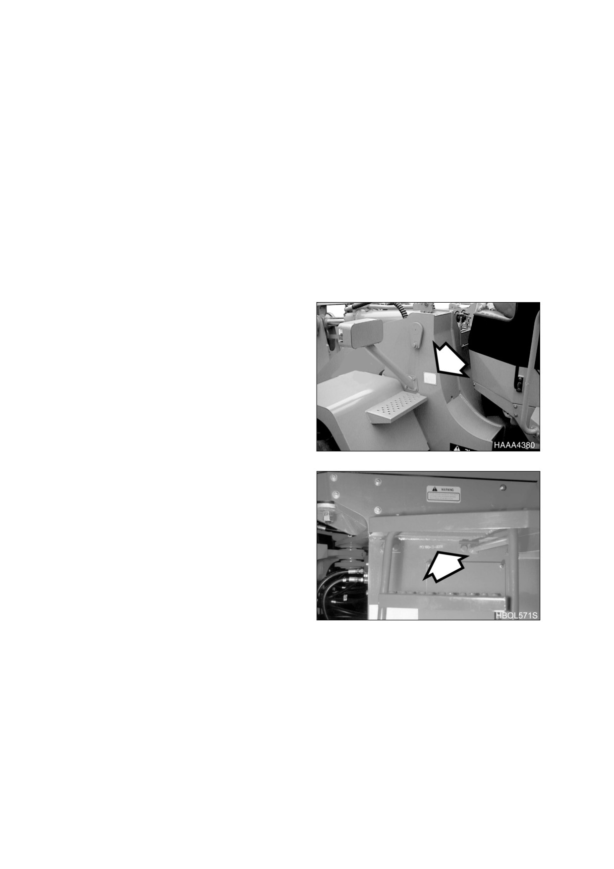
SERIAL NUMBERS
There are two serial number plates attached to
the body of wheel loader.
Please make note of these numbers and their
locations. These will be required whenever
warranty service work is requested.
Main Serial Number
Main serial number plate is on left side of front
frame above fender (Figure 1).
Figure 1
The number is also stamped in the rear frame
on the left side just below the cab (Figure 2).
Figure 2
022-00029AE Operation and Maintenance Manual
Inspection, Maintenance and Adjustment 4-1
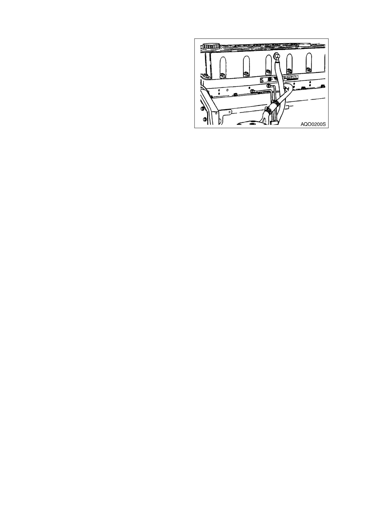
Engine Serial Number
The engine name plate (identification label) is
on the fuel pump side of the engine, on the
rocker housing (Figure 3).
Figure 3
SAFETY PRECAUTIONS
1.
Before performing any maintenance checks, move pilot cutoff switch to "LOCKED" position. Place a
Warning Tag on controls so that no one begins to operate machine while maintenance checks are
being performed.
2.
Clean up all fuel spills. Fuel spills are hazardous, especially around engine.
3.
Inspect all fuel lines for leakage. Replace any lines, fittings, O-rings, or filters that show signs of wear
or damage.
4.
If a test procedure requires engine to be running, use two people and keep all unnecessary
personnel away from machine.
4-2 Inspection, Maintenance and Adjustment
022-00029AE Operation and Maintenance Manual

TABLE OF RECOMMENDED LUBRICANTS
IMPORTANT
Do not use lubricants other than those recommended, without prior written approval from
DOOSAN.
NOTE: Refer to Maintenance Intervals Table for application points.
LUBRICANT
LUBRICANT
HYDRAULIC OIL
ENGINE OIL*
AXLE GEAR OIL
MANUFACTURER
GREASE
CALTEX
CALTEX HD32
CALTEX RPM or
MULTIFAC EP
MULTIPURPOSE
EP90
DELO 300
EXXON/ESSO
NUTO (ANTI-
EXXON 15W40
RONEX MP #2 or
SPARTAN EP220
WEAR)
or
RONEX MP #1
HD 32 (BELOW
(COLD TEMPS)
EXXON GX
0°C (32°F)) or
80W90
HD 46 (ABOVE
0°C (32°F)) or
TERESSTIC
(ANTI-RUST)
MOBIL
MOBIL
DELVAC 1300 or
MOBIL FAW #2
MOBILUBE HD
or
80W90
DTE 13M (ALL-
SUPER 15W40
TEMP) or
MOBIL FAW #1
(COLD TEMPS)
DTE 24
(SUMMER)
SHELL
TELLUS 32
ROTELLA
ALVANIA EP #2
SPIRAX HD
80W90 or
T15W40
DONAX TD
(TRANSMISSION)
PENNZOIL
PENNZBELL
LONGLIFE
PENNZOIL 705
PENZOIL
EP #2
MULTIPUPOSE
AW 32 (BELOW
SAE15W40
4092 or
0°C (32°F)) or
80W90
AW 46 (ABOVE
0°C (32°F))
DRYDEN
PARADENE
DIESELALL
EP #2 (RED)
AP80W90
PLUS 15W40
AW 32 (BELOW
0°C (32°F)) or
AW 46 (ABOVE
0°C (32°F))
* Engine oil must meet ACEA-E2, ACEA-E3 or API-CH-4 EQUIVALENT and be SAE 15W40 or 10W40.
022-00029AE Operation and Maintenance Manual
Inspection, Maintenance and Adjustment 4-3
LUBRICANT
LUBRICANT
HYDRAULIC OIL
ENGINE OIL*
AXLE GEAR OIL
MANUFACTURER
GREASE
CHEVRON
AW MV 32
DELO 400
DELO GREASE
DELO GEAR OIL
(BELOW 0°C
15W40
EP-2
or
(32°F)) or
RPM UNIV GEAR
AW MV 46
80W90
(ABOVE 0°C
(32°F))
TEXACO
RANDO
URSA SUPER
STAR PLEX 2
MULTIGEAR
PLUS 15W40 or
EPSAE 80W90
HD32 (BELOW
STAR PLEX
0°C (32°F)) or
URSA PREMIUM
PREMIUM
TDX 15W40
HD46 (ABOVE
0°C (32°F))
IDEMITSU
DAPHNE KOSAN
APOROIL
DAPHNE
APOROIL GEAR
KOSAN
46WR
MOTIRE S300
CORRONE #2
HE 90
NIPPON SEIKIYU
SUPER
LIPANOC
NISEKI SP90 or
HIGHLAND S26
GREASE
EP90
or 32
TOTAL
TOTAL EQUIVIS
TOTAL
TOTAL MUTRIS
TOTAL DA80W90
ZS46
EP #2
* Engine oil must meet ACEA-E2, ACEA-E3 or API-CH-4 EQUIVALENT and be SAE 15W40 or 10W40.
Lubricant Manufacturer
Transmission Gear Oil
SAME AS ENGINE OIL
SAE 15W40 (API CD AND ABOVE)
CAUTION!
Do not mix oils from different manufacturers. DOOSAN does not endorse specific brands but
does suggest that owners select quality oils whose suppliers provide assurance that required
standards will always be met or exceeded.
IMPORTANT
Fluctuating daily or weekly extremes of temperature, or operation in sub-zero freezing weather
may make it impractical to use straight weight lubricants. Use good judgement in selecting
lubricant types that are appropriate for climate conditions.
4-4 Inspection, Maintenance and Adjustment
022-00029AE Operation and Maintenance Manual

FLUID CAPACITIES
Component
Capacity
Engine
Oil Pan with Filter
34 liters
(9 U.S. gal.)
NOTE: The filter holds an additional 1
liter (1 qt) of oil.
Cooling System
60 liters
(16 U.S. gal.)
Fuel Tank
480 liters
(127 U.S. gal.)
Hydraulic Oil Tank
280 liters
(74 U.S. gal.)
Transmission
50 liters
(13 U.S. gal.)
Axles
Front Differential
32 liters
(8.5 U.S. gal.)
Front Hub Reduction Gear
9 liters
(2.4 U.S. gal.) Each End.
Rear Differential
32 liters
(8.5 U.S. gal.)
Rear Hub Reduction Gear
9 liters
(2.4 U.S. gal.) Each End.
022-00029AE Operation and Maintenance Manual
Inspection, Maintenance and Adjustment 4-5
MAINTENANCE INTERVALS
10 HOUR / DAILY SERVICE
•
Grease Front Attachment Pins (See page
•
Inspect Seat Belt for Proper Operation (See
4-8)*
page 4-14)
•
Inspect All Tires for Correct Tire Pressure
•
Inspect the Structure for Cracks and Faulty
and Signs of Damage or Abnormal Wear
Welds (See page 4-14)
(See page 4-8)
•
Check the Operation of All Switches (See
•
Check Engine Oil Level (See page 4-8)
page 4-15)
•
Check Transmission Oil Level (See page
•
Check the Operation of All Exterior Lights,
4-9)
Horn and Control Console Indicator and
•
Check Hydraulic System Oil Level (See
Monitor Lights (See page 4-15)
page 4-10)
•
Start Engine, Check Starting Ability, and
•
Check for Leaks in the Hydraulic System
Observe Exhaust Color at Start-up and at
(See page 4-11)
Normal Operating Temperature. Listen for
•
Refill Fuel (See page 4-12)
Any Abnormal Sounds (See page 4-15)
•
Check for Leaks in the Fuel System (See
•
Check Operation of All Controls (See page
page 4-12)
4-15)
•
Drain Fuel Condensation (See page 4-12)
•
Inspect Engine Fan Blade (See page 4-16)
•
Check Coolant Level (See page 4-13)
•
Check Engine Drive Belt Wear (See page
•
Check Antifreeze Protection Levels (See
4-16)
page 4-14)
•
Check Air Intake System (See page 4-17)
•
Check Level of Window Washer Fluid (See
•
Check Crankcase Breather Tube (See
page 4-14)
page 4-17)
•
Inspect the Bucket Teeth and Side Cutters
for Signs of Wear (See page 4-14)
50 HOUR / WEEKLY SERVICE
•
Perform All 10 Hour / Daily Service Checks
•
Change Engine Oil and Filter (Initial) (See
(See page 4-18)
page 4-23)*
•
Grease Front Attachment Pins (See page
•
Hydraulic Full Flow Filter Replacement
4-18)
(Initial) (See page 4-24)*
•
Grease Steering Cylinder Rod and Base
•
Check Water Pump Belt Tension -
Ends (See page 4-23)
Alternator, and Air Conditioner Belt (Initial)
•
Grease Upper and Lower Center Pins (See
(See page 4-24)*
page 4-23)
•
Clean Exterior of Radiator, Oil Cooler and
Air-conditioner Evaporator (See page 4-24)
* Break-In
4-6 Inspection, Maintenance and Adjustment
022-00029AE Operation and Maintenance Manual
250 HOUR / MONTHLY SERVICE
•
Perform All 10 Hour / Daily and 50 hour
•
Check Water Pump Belt Tension (See page
Service Checks (See page 4-25)
4-29)
•
Grease Drive Shaft Center Bearing (See
•
Change Engine Oil and Filter (See page
page 4-25)
4-30)
•
Replace Hydraulic System Pilot Filter (See
•
Replace DCA4 Coolant Filter Cartridge
page 4-25)
(See page 4-31)
•
Check Engine Air Cleaner Pre-cleaner (See
•
Replace Fuel Filter (See page 4-33)
page 4-26)
•
Axle Differential and Planetaries Oil
•
Hydraulic Full Flow Filter Replacement
Replacement (Initial) (See page 4-34)
(See page 4-27)
•
Check Differential Gear Oil (See page 4-34)
•
Drain Water From Hydraulic Oil Tank (See
•
Check Planetary Gear Oil (See page 4-34)
page 4-28)
•
Replacing Transmission Oil and Filter
•
Clean Air Cleaner (See page 4-28)
(Initial) (See page 4-34)*
500 HOUR / 3 MONTH SERVICE
•
Perform All 10 Hour / Daily, 50, 150, and
•
Clean Air Conditioning Filter (See page
250 Hour Service Checks (See page 4-35)
4-35)
•
Clean Exterior of Radiator, Oil Cooler and
Air-conditioner Evaporator (See page 4-35)
1,000 HOUR / 6 MONTH SERVICE
•
Perform All 10 Hour / Daily, 50, 150, 250,
•
Clean Fuel Tank and Strainer (See page
and 500 Hour Service Checks (See page
4-40)
4-37)
•
Check Air Condition Refrigerant (See page
•
Change Radiator Coolant (See page 4-37)
4-41)
•
Drain and Replace Transmission Oil and
•
Check and Adjust Engine (See page 4-41)
Filter (See page 4-38)
1,500 HOUR / 9 MONTH SERVICE
•
Perform All 10, 50, 150, 250, and 500 Hour
•
Axle Differential and Planetaries Oil
Service Checks (See page 4-42)
Replacement (See page 4-42)
•
Replace Outer and Inner Air Cleaner
Elements (See page 4-42)
2,000 HOUR / ANNUAL SERVICE
•
Perform All 10 Hour / Daily, 50, 150, 250,
•
Clean Hydraulic Oil Suction Strainer (See
500 and 1000 Hour Service Checks (See
page 4-47)
page 4-44)
•
Check Vibration Damper (See page 4-47)
•
Replace Hoses (See page 4-44)
•
Check Brake Accumulator (See page 4-48)
•
Bleed Brakes (See page 4-44)
•
Check Steering, Brake, Drive Shaft,
•
Drain and Replace Hydraulic Oil (See page
Engine, and Fuel System (See page 4-48)
4-45)
* Break-In
022-00029AE Operation and Maintenance Manual
Inspection, Maintenance and Adjustment 4-7
10 HOUR / DAILY SERVICE
GREASE FRONT ATTACHMENT PINS
NOTE: Fittings are greased daily, or every 10 hours, for the first 100 hours of operation to comply
with new machine break-in requirements. After that, greasing should be done every 50
hours. If bucket is being used in water, grease fittings immediately after machine is
removed from water. Follow procedure printed under the 50 hour maintenance interval
“Grease Front Attachment Pins” on page 4-18.
INSPECT ALL TIRES FOR CORRECT TIRE PRESSURE AND SIGNS OF DAMAGE OR ABNORMAL
WEAR
1.
Inflate tires to proper operating pressure for working conditions. See
“Tires and Wheels” on
page 4-57.
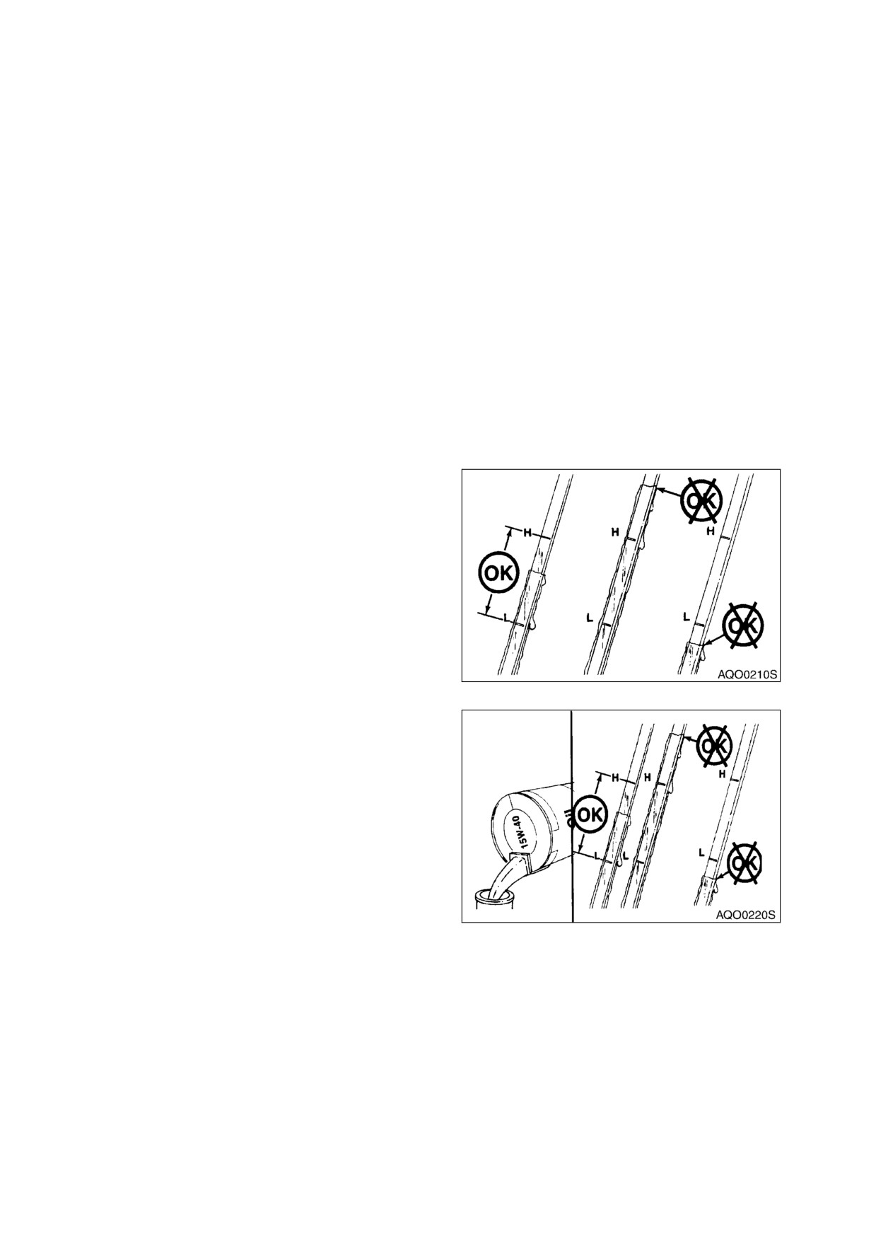
CHECK ENGINE OIL LEVEL
NOTE: When checking level using a dipstick always remove and wipe it clean before making final
level check.
1.
Check level of engine oil every day before
starting engine.
2.
Remove engine oil dipstick. (Figure 4). Oil
level must be between "LOW" and "FULL"
marks.
NOTE: If oil is above "HIGH" mark on
dipstick, some must be drained
to return oil to proper level.
Figure 4 ENGINE OIL DIPSTICK
3.
To add oil, remove engine oil fill cap
(Figure 5).
Figure 5 ENGINE OIL FILL CAP
4-8 Inspection, Maintenance and Adjustment
022-00029AE Operation and Maintenance Manual
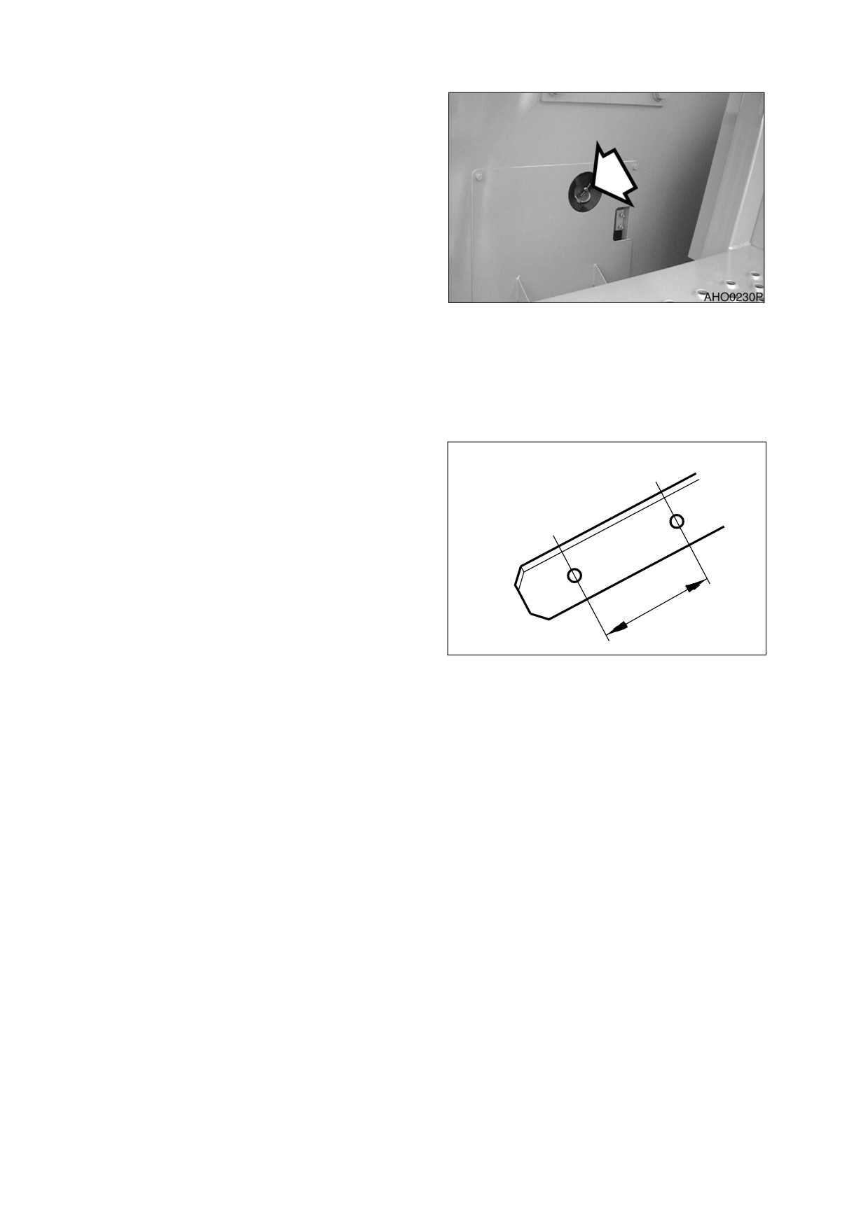
CHECK TRANSMISSION OIL LEVEL
NOTE: When checking level using a
dipstick always remove and
wipe it clean before making
final level check.
1.
Use two people to perform this operation.
2.
Start engine and move machine to a level
area.
3.
Place transmission lever in "NEUTRAL."
4.
Apply parking brake.
Figure 6
5.
Allow engine to idle until engine
temperature is between 82°C (180°F) and
93°C (200°F).
6.
Remove transmission dipstick (Figure 6).
Wipe dipstick clean and then insert it back
into transmission.
7.
Remove dipstick and check oil level mark.
Oil level must be between “COLD” and
H
“HOT” marks (Figure 7).
8.
To add oil, remove transmission fill cap
(Figure 6) from transmission oil filler pipe.
C
9.
Shutdown engine when done.
HAOC281L
Figure 7
022-00029AE Operation and Maintenance Manual
Inspection, Maintenance and Adjustment 4-9
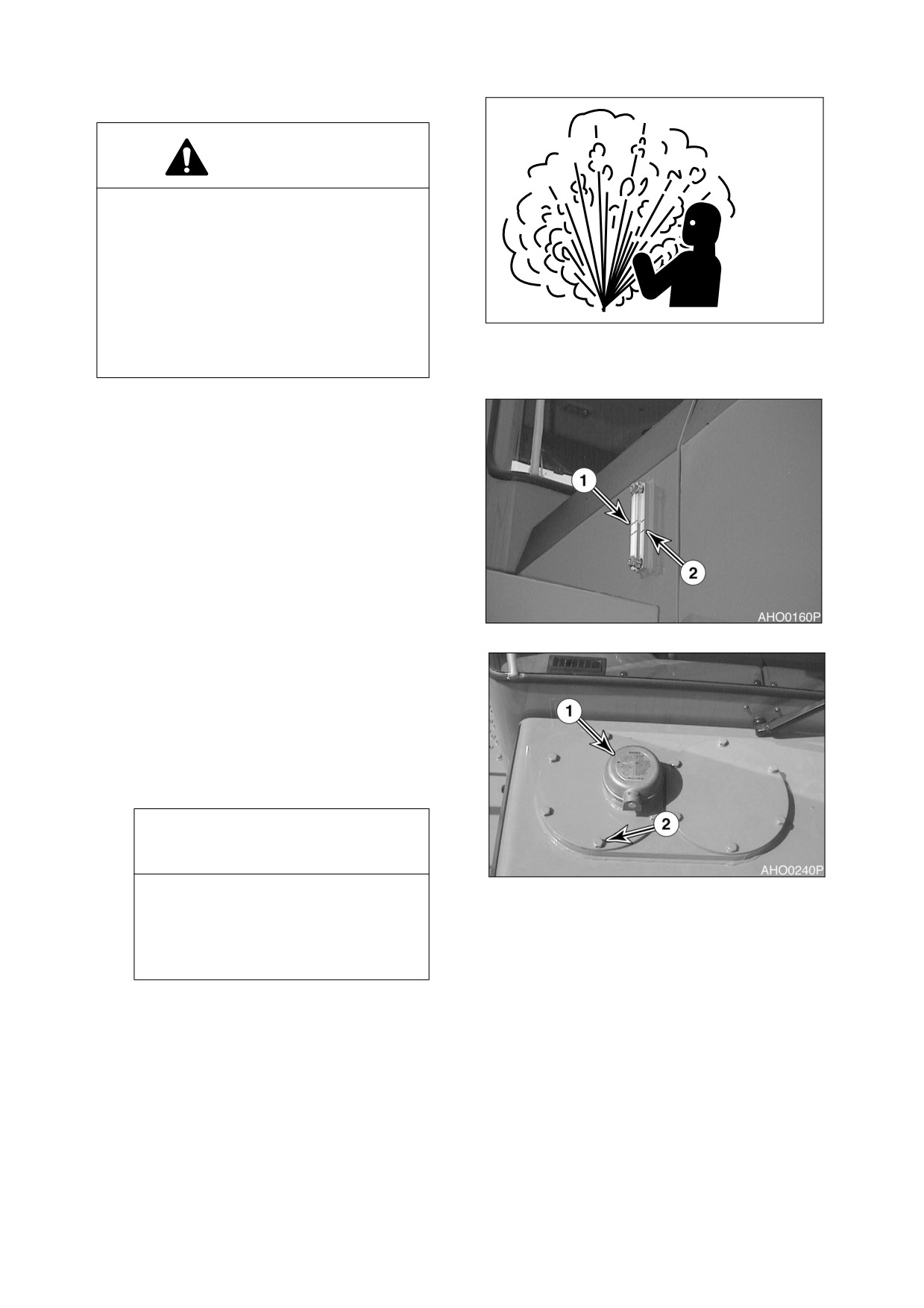
CHECK HYDRAULIC SYSTEM OIL LEVEL
WARNING!
The hydraulic oil will be hot after normal
machine operation. Allow system to cool
before attempting to service any of the
hydraulic components.
The hydraulic tank is pressurized. Press
button in center of breather to allow the
HAOA060L
pressurized air to vent. After the pressure
Figure 8
has been released, it is safe to remove
either the fill cap or service covers.
1.
Move machine to a level area and
shutdown engine.
2.
Apply parking brake.
3.
Lower bucket to ground.
4.
Check sight gauge that is attached to
hydraulic reservoir. Oil level must be
between upper limit (1, Figure 9) and lower
limit (2) shown on gauge.
Figure 9
5.
To add hydraulic oil, first press down on
pressure relief button
(1, Figure
10) to
release system pressure.
6.
Remove bolts (2, Figure 10), cover and O-
ring from fill hole.
7.
Add oil to proper level by checking sight
glass (Figure 9).
IMPORTANT
Do not fill above "H" mark on sight
Figure 10
gauge. Overfilling can result in
damage to equipment and oil leaking
from hydraulic tank due to
expansion.
4-10 Inspection, Maintenance and Adjustment
022-00029AE Operation and Maintenance Manual
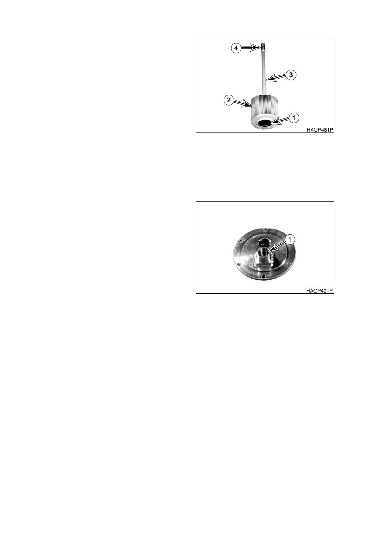
The hydraulic oil filler cover also serves as the
hydraulic oil strainer access cover. It is important
to replace this cover and the components in the
proper order and alignment.
The filter element (2, Figure 11), retaining rod
(2) and spring (4) are assembled as shown in
Figure 11. The hole (1) in the base of the filter
element fits over a circular base in the bottom of
the reservoir. The retaining rod (3) screws into
the top of the filter element (2), but the spring (4)
slides over the top of the rod. Be certain that this
spring does not fall into the tank during
reassembly.
Figure 11
1.
If filter assembly was removed, insert
assembly into the reservoir and check to
make sure it is securely in place.
2.
Check O-ring for damages and replace if
necessary. Check position of O-ring at
surface of hole.
3.
Place the cover on the access hole. Make
sure the spring retaining cup (1, Figure 12)
in the lower section of the cover is lined up
with the spring. The filter assembly rod
must be in a vertical position and
perpendicular to the base of the reservoir.
The cover can be rotated to align the rod
into a vertical position.
4.
Tighten mounting bolts to 4.84 kg•m (35 ft
lb).
Figure 12
CHECK FOR LEAKS IN THE HYDRAULIC SYSTEM
1.
Perform a daily walk-around inspection to make sure that the hoses, piping, fittings, cylinders and
hydraulic motors are not showing any signs of leakage. If any is noted, determine the source of the
leak and repair.
022-00029AE Operation and Maintenance Manual
Inspection, Maintenance and Adjustment 4-11
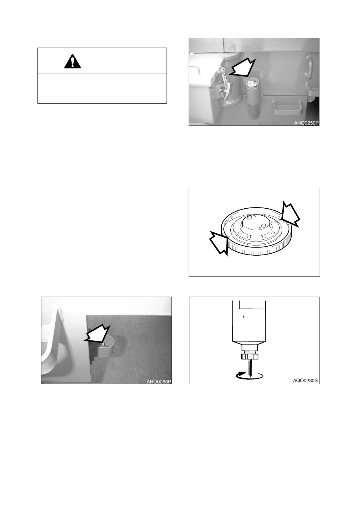
REFILL FUEL
WARNING!
Use extreme safety precautions while
refueling to prevent explosions or fire.
Immediately clean up any spilt fuel.
1.
At end of each work day, fill fuel tank. Add
fuel through fuel filler pipe
(Figure
13).
When working at a temperature of 0°C
Figure 13
(32°F) or higher, use ASTM No. 2-D or its
equivalent. At temperatures below
0°C
(32°F) use ASTM No. 1-D or its equivalent.
NOTE: See
“Fluid Capacities” on
page 4-5 for capacity.
2.
Securely tighten cap after fueling.
NOTE: If breather holes in cap are
clogged, a vacuum may form in
the tank preventing proper fuel
flow to engine. Keep holes in
fuel cap clean.
CHECK FOR LEAKS IN THE FUEL SYSTEM
1.
Perform an inspection of engine
compartment to verify that fuel system is
not leaking. If any is noted, determine the
source of leak and repair.
HAOC510L
Figure 14
DRAIN FUEL CONDENSATION
Figure 15
Figure 16
1.
Open fuel tank drain valve. (Figure 15). Allow any condensed water or sediment to drain out of tank.
Also open drains on Primary and Secondary fuel filters and drain out any water or sediment. (Figure
16). Catch drained material in a container. Properly dispose of drained material.
4-12 Inspection, Maintenance and Adjustment
022-00029AE Operation and Maintenance Manual

CHECK COOLANT LEVEL
WARNING!
Never open radiator when it is hot. Scalding liquid inside a hot radiator is under pressure.
Removing cap from a hot radiator could cause a person to be sprayed and burned from liquid
inside. Wait for radiator temperature to cool down before removing cap.
Figure 18
Figure 17
1.
Remove fill cap from radiator (Figure 18). Check level of coolant inside radiator. If low, add coolant to
fill radiator to a point that is 10 - 20 mm (1/2 - 3/4") below top of overflow pipe. If temperature is below
freezing, see “Check Antifreeze Protection Levels” on page 4-14 for antifreeze protection. Use the
table to calculate a proper mixture of anti-freeze and water to provide level of protection necessary
for expected temperature.
022-00029AE Operation and Maintenance Manual
Inspection, Maintenance and Adjustment 4-13
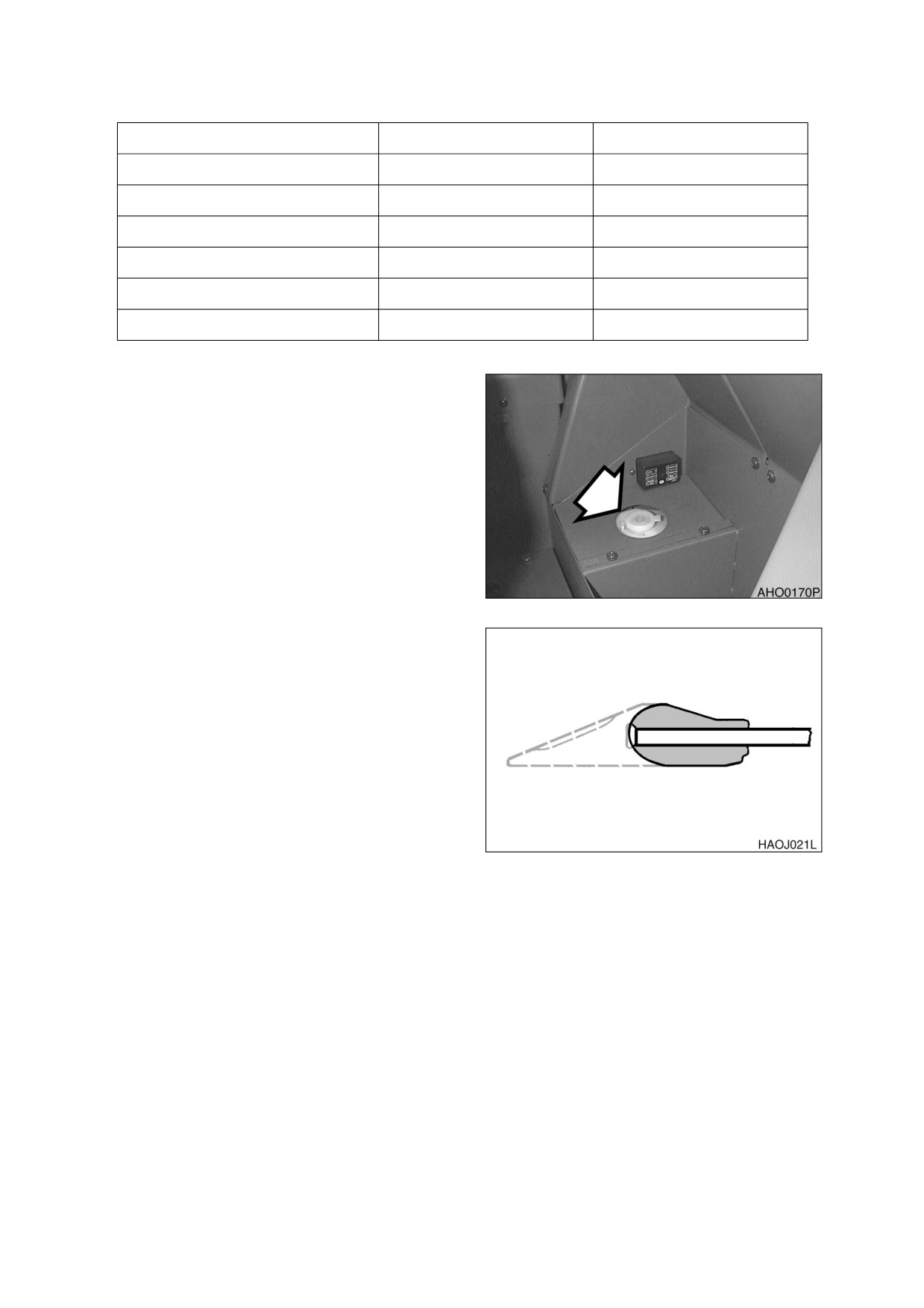
CHECK ANTIFREEZE PROTECTION LEVELS
AMBIENT TEMPERATURE
COOLING WATER
ANTIFREEZE
-10°C (15°F)
80%
20%
-15°C (5°F)
73%
27%
-20°C (-5°F)
67%
33%
-25°C (-15°F)
60%
40%
-30°C (-20°F)
56%
44%
-40°C (-30°F)
50%
50%
CHECK LEVEL OF WINDOW WASHER FLUID
1.
Check fluid level in windshield washer
tank, in the storage box of the rear of the
seat.
2.
Open fill cap and add fluid.
NOTE: Use a washer liquid that is
rated for all seasons. This will
prevent freezing during cold
weather operation.
Figure 19
INSPECT THE BUCKET TEETH AND SIDE
CUTTERS FOR SIGNS OF WEAR
1.
On a daily basis, inspect bucket teeth to
make sure that tooth wear or breakage has
not developed.
2.
Do not allow replaceable bucket teeth to
wear down to the point that bucket adapter
is exposed. (Figure 20)
NOTE: These instructions are only for
DOOSAN OEM buckets. If you
are using other manufacturers’
buckets, refer to their specific
Figure 20
instructions.
INSPECT SEAT BELT FOR PROPER OPERATION
INSPECT THE STRUCTURE FOR CRACKS AND FAULTY WELDS
1.
During the daily walk-around inspection and when greasing the machine, look for any visible damage
to the machine. Repair or replace any damaged parts before operating machine.
4-14 Inspection, Maintenance and Adjustment
022-00029AE Operation and Maintenance Manual
CHECK THE OPERATION OF ALL SWITCHES
1.
Verify working condition of all switches before starting engine.
CHECK THE OPERATION OF ALL EXTERIOR LIGHTS, HORN AND CONTROL CONSOLE
INDICATOR AND MONITOR LIGHTS
1.
Turn engine starter switch to the "ON" position and observe all indicator lights.
2.
Restore operation of any light bulbs that do not turn "ON" at this point.
3.
Sound the horn. Repair or replace if required.
4.
Turn "ON" and inspect all exterior work lights. Replace any monitors, burned out bulbs or cracked or
broken housings or lenses.
START ENGINE, CHECK STARTING ABILITY, AND OBSERVE EXHAUST COLOR AT START-UP
AND AT NORMAL OPERATING TEMPERATURE. LISTEN FOR ANY ABNORMAL SOUNDS
CHECK OPERATION OF ALL CONTROLS
IMPORTANT
Cold weather operation requires that the operator fully warm up the hydraulic oil before
beginning machine operation. Follow all warm up instructions listed in the Operating Instruction
section of this manual. Make sure to cycle oil through all of the components, including all
cylinders, both travel motors and the swing motor. Cold hydraulic oil in the lines and
components needs to be warmed before beginning full operation. If this is not done, damage to
the cylinders or hydraulic motors can occur.
1.
With engine at rated speed, operate all of the controls.
2.
Follow cold weather hydraulic system warm-up procedures.
3.
Note any slow operations or unusual movements. Determine the cause and repair fault before
operating.
022-00029AE Operation and Maintenance Manual
Inspection, Maintenance and Adjustment 4-15
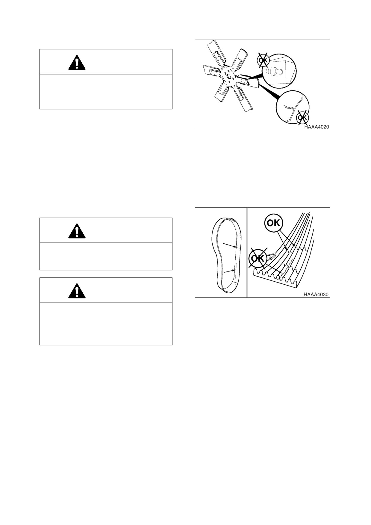
INSPECT ENGINE FAN BLADE
WARNING!
Personal injury can result from a fan blade
failure. Never pull or pry on the fan. This
can damage the fan blade(s) and cause
fan failure.
NOTE: Manually rotate the crankshaft
by using a wrench on the
accessory drive pulley nut.
Figure 21
1.
An inspection of the cooling fan is required
daily. check for cracks, loose rivets, bent or
loose blades, and for contact between the
blade tips and the fan shroud. Check the
fan to make sure it is securely mounted.
Tighten the bolts if necessary. Replace
any fan that is damage.
CHECK ENGINE DRIVE BELT WEAR
WARNING!
Keep clear of engine fan and fan drive
belts when the engine is running. Rotating
fan and belt contact can cause injury.
WARNING!
Figure 22
When checking, adjusting or replacing
drive belts, care must be taken to prevent
accidental cranking of the engine. Be sure
the starter switch is in the "OFF" position
and the controls are tagged.
1.
Replace badly worn, greasy or severely cracked belts immediately. These conditions prevent proper
belt function. Visually inspect the belt. Check the belt for intersecting cracks. Transverse (across the
belt width) cracks are acceptable. Longitudinal (direction of belt length) cracks that intersect with
transverse cracks are not acceptable. Replace the belt if it is frayed or has pieces of material missing.
2.
Before installing new belts, make sure all pulley grooves are clean and not worn. Replace pulley, if
damaged, or if the grooves are worn.
3.
All pulley support bearings, shafts, and brackets must be in working order.
4.
When replacing belts and pulleys, pulley alignment must be checked with belts tensioned and
brackets securely clamped. A misalignment that can be detected by the naked eye is detrimental to
belt performance.
4-16 Inspection, Maintenance and Adjustment
022-00029AE Operation and Maintenance Manual
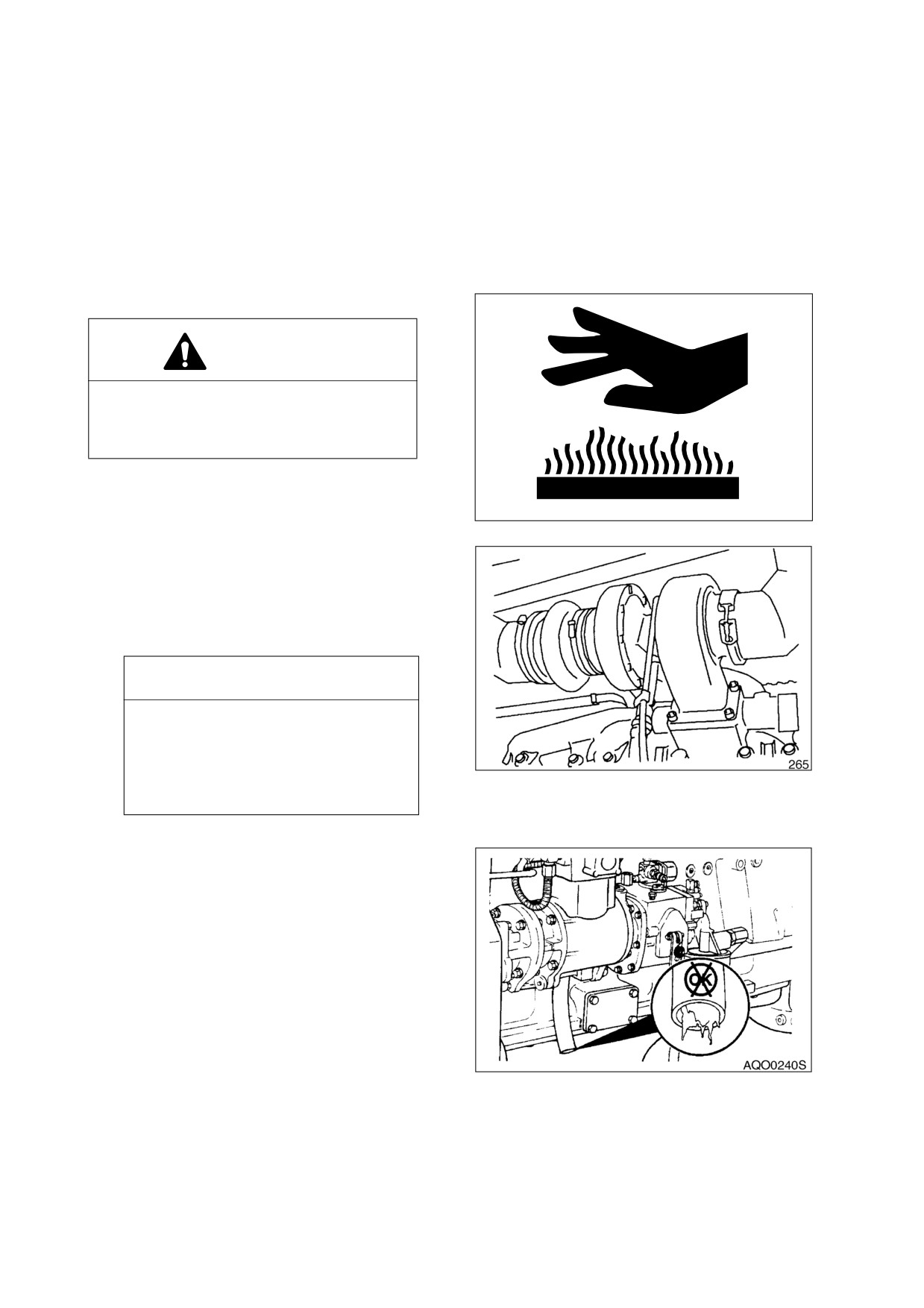
5.
Do not force the belts into the pulley grooves by prying with a screwdriver or pry bar. This will damage
the belt side cords which will cause the belts to turn and result in complete destruction of the belts in
operation.
6.
Belts on new machines and replacement belts lose their tension as they seat into the pulley grooves.
Check the tension of new belts at 20 hour intervals until tension is stabilized and thereafter, every 250
hours. If the tension falls below the required minimum, the belt slips damaging the belts and pulley
grooves.
NOTE: When operating in abrasive conditions, check tension every 100 hours.
CHECK AIR INTAKE SYSTEM
CAUTION!
Hot engine components can cause burns.
Avoid contact with hot engine
components
1.
Park the machine on a level surface, apply
the parking brake, lower the attachment to
HAOA050L
the ground, and stop the engine.
Figure 23
2.
Check the engine intake hose, and hose
bands for damage and tightness.
3.
If damaged, wrinkled or loose, replace or
retighten or contact your nearest loader
dealer.
IMPORTANT
Severe engine damage will result
from running with unfiltered air.
Do not operate engine if any leaks or
defects are found on air intake
Figure 24
system.
CHECK CRANKCASE BREATHER TUBE
1.
Check the crankcase breather tube daily
during cold weather operations for ice
buildup, which could obstruct the tube.
NOTE: If ice buildup is present, remove
the breather tube and clear the
obstruction.
Figure 25
022-00029AE Operation and Maintenance Manual
Inspection, Maintenance and Adjustment 4-17
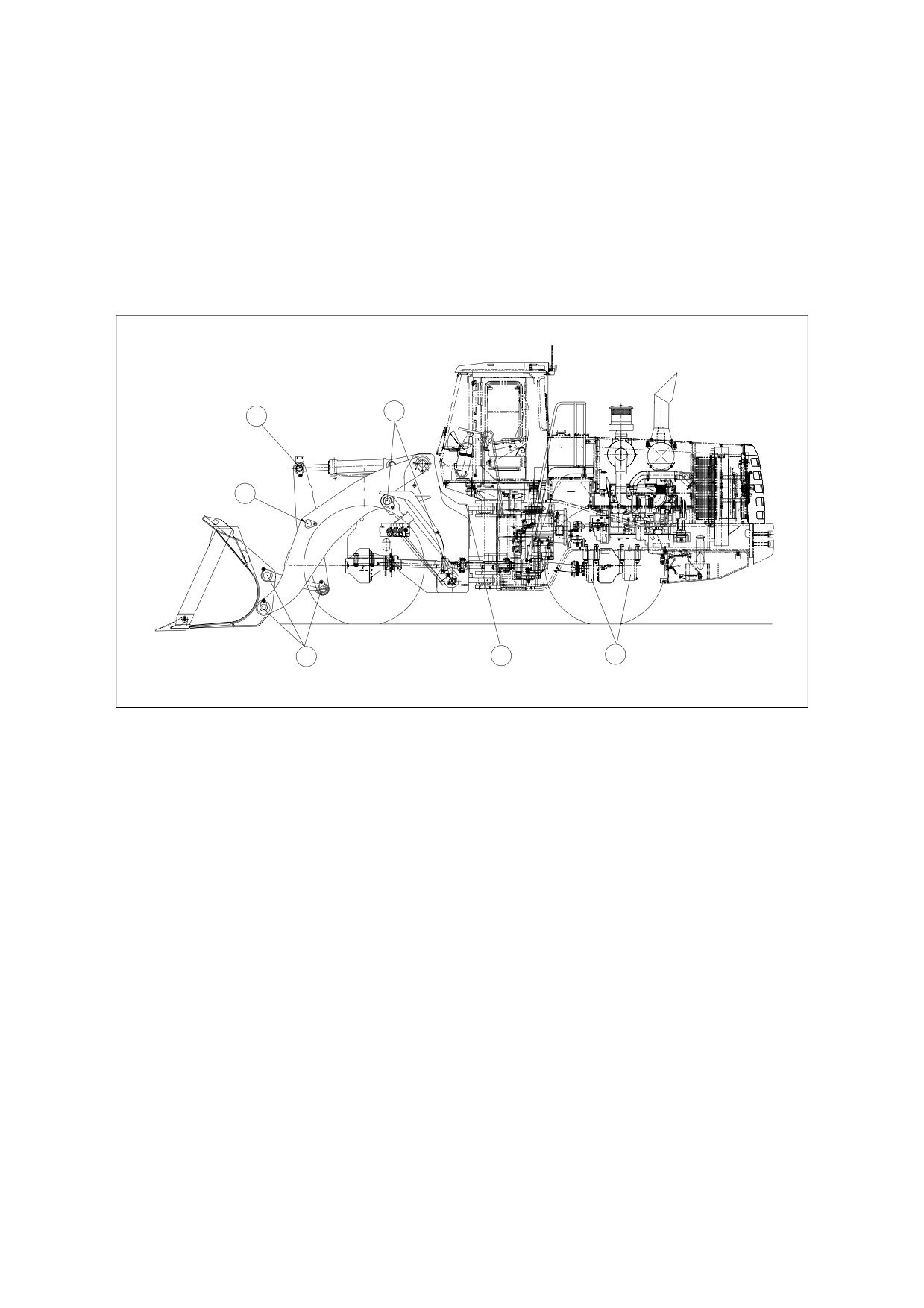
50 HOUR / WEEKLY SERVICE
PERFORM ALL 10 HOUR / DAILY SERVICE CHECKS
GREASE FRONT ATTACHMENT PINS
1.
Following fittings are greased daily, or every 10 hours, for first 100 hours of operation to comply with
new machine break-in requirements. After that, greasing should be done every 50 hours. If bucket is
being used in water, grease fittings immediately after machine is removed from water.
D
C
B
E
F
AQO0180L
Figure 26
4-18 Inspection, Maintenance and Adjustment
022-00029AE Operation and Maintenance Manual