MANITOU MT 728, MT 732, MT 928, MT 932, MT 1030 S, MT 1030 S Turbo. Operator's Manual - part 2

15 - PREARRANGED TRAILER LOCKING
MT 732 Série D-E3
MT 932 Série D-E3
MT 1030 S Série 4-E3
MT 1030 S Turbo Série 4-E3
Enables the hydraulic connection of a braked trailer (see: 2 - DESCRIPTION: TOWING PIN
AND HOOK).
1
16 - CLEANFIX SELF-CLEANING FAN
MT 732 Série D-E3
MT 932 Série D-E3
MT 1030 S Série 4-E3
MT 1030 S Turbo Série 4-E3
This system, operated by switch 1, cleans the radiator core and the grille of the engine
cover by reversing the air flow.
When in use, beware of the risk of projection into the eyes.
Position A: The indicator light is on, the fan operates in self-cleaning mode for a few
seconds once ever y 3 minutes.
Position B: The indicator light is off, the fan is in normal operating mode.
B
1
A
18 - ATTACHMENT CIRCUIT WITH QUICK-RELEASE COUPLERS
MT 728 Série D-E3
MT 928 Série D-E3
Enables the use of a hydraulic attachment.
OPERATION
- Raise lever 1 and turn to the left or right.
1
2-65

19 - SINGLE SIDE-SHIFT CARRIAGE (TSDL)
TSDL
MT 1030 S Série 4-E3
MT 1030 S Turbo Série 4-E3
The single side-shift carriage (TSDL) is only compatible with the following attachments:
• floating fork carriage (TFF)
• tilting fork carriage (PFB)
• loading bucket (CBR)
• concrete bucket (BB, BBG)
• spout bucket (GL)
• crane boom and crane boom with winch (P, PT, PO, PC)
• winch (H)
It is prohibited to use any other attachments on the TSDL.
If it is being used with a loading bucket (CBR), the single side-shift carriage MUST be centred and no
side-shift operations performed.
WITH COUPLER ON BOOM HEAD
A
SINGLE SIDE-SHIFT CARRIAGE
- Put the valve in position B, and used hydraulic control of the attachment of the lift truck.
B
ATTACHMENT
- Put the valve in position A, and used hydraulic control of the attachment of the lift truck.
WITH BOOM HEAD ELECTROVALVE
SINGLE SIDE-SHIFT CARRIAGE
- Move the lever to left or right.
1
ATTACHMENT
- Hold button 1 down and move the lever to left or right.
WITH BOOM HEAD ELECTROVALVE
+PREARRANGED HYDRAULIC ATTACHMENT
LOCKING
A
SINGLE SIDE-SHIFT CARRIAGE
- Move the lever to left or right.
B
ATTACHMENT
- Set the valve to position A, hold down button 1 and move the lever to left or right.
PREARRANGED HYDRAULIC ATTACHMENT LOCKING
- Set the valve to position B, hold down button 1 and move the lever to left or right.
1
2-66

20 - LIFTING RING ON SINGLE CARRIAGE
Kg
CONDITIONS OF USE
Kg
Kg
Follow the instructions given in the instruction manual (see: 1 - OPERATING
AND SAFETY INSTRUCTIONS: INSTRUCTIONS FOR HANDLING A LOAD).
- The lifting ring must be used WITHOUT FORKS AND ATTACHMENTS,
but the angle of inclination of the carriage must be same
as when the forks are used in the horizontal position.
Kg
Kg
Kg
Kg Kg Kg
- Do not change the angle of the carriage while using the lifting
ring.
- The lifting hook, the chains and slings shall have a minimum
capacity of 3000 kg with a factor of safety against breakage of
4.
Kg
Kg
Kg
Kg
HANDLING WITH NO MOVEMENT OF THE LIFT TRUCK
- Whether on stabilisers or on tyres, the lateral attitude must not exceed 1 % and the
longitudinal attitude must not exceed 8,75 % (5°).
- The bubble of the level indicator must remain within the outer circle and be centred in the
longitudinal direction.
HANDLING WITH MOVEMENT OF THE LIFT TRUCK
- The lateral attitude must not exceed 8,75 % (5°). The bubble must remain within the outer
circle.
LOAD CHARTS AND FUNCTION SHEETS
MT732 + TS AS 3T
MT 732 + TS AS 3T
MT 732 Série D-E3
The load charts are given for use without forks and
40°
45°
63°
without attachments.
7
36km/h Maxi
(10m/s)
6
30°
45°
5,55
3000KG
0 KG
Maxi
5
MAXI
4
20°
3
3000KG
MAXI
2
1400 KG
1
0,3m Maxi
1,44km/h (0,4m/s)
0°
Maxi
0m
1,50mMaxi
-3°
4
3
2
1
0m
3mMini
3,20
2,15
0,70
3,41
2,60
1,85
2-67

LOAD CHARTS AND FUNCTION SHEETS
MT932 + TS AS 3T
MT 932 + TS AS 3T
MT 932 Série D-E3
The load charts are given for use without forks and
45°
55°
62.4°
10
40°
without attachments.
9
36km/h Maxi
(10m/s)
8
3000KG
45°
6.87
7
MAXI
30°
Maxi
6
0KG
5
2500KG
20°
4
3
3000KG
MAXI
10°
2
1
500KG
0,3m Maxi
1,44km/h (0,4m/s)
Maxi
0°0m
1,50mMaxi
-3.7°
-1
7
6
5
4
3
2
1
0m
3mMini
5.70
4.25
3.30
1.98
0.58
5.78
4.70
3.70
2.65
1.80
LOAD CHARTS AND FUNCTION SHEETS
MT 1030 S Série 4-E3
MT1030S + TS AS 3T
MT 1030 S Turbo Série 4-E3
The load charts are given for use without forks and without attachments.
36km/h Maxi
(10m/s)
45°
Maxi
MT1030S + TS AS 3T
MT1030S + TS AS 3T
2500KG
MAXI
10
10
9.86
60°
65.4°
9
9
0,3m Maxi
1,44km/h (0,4m/s)
Maxi
50°
8
45°
8
1,1m Maxi
7.54
7
40°
7
40°
3mMini
0KG
6
6
30°
30°
5
5
4
4
20°
20°
3
3
2
2
10°
10°
1
1
0°
0
0
0.4°
-1
-4.1°
-1
7
6
5
4
3
2
1
0m
7
6
5
4
3
2
1
0m
2-68
3- MAINTENANCE
3-1
3-2
TABLE OF CONTENTS
MANITOU ORIGINAL SPARE PARTS AND EQUIPMENT
3-4
START-UP CHECKLIST
3-5
FILTERS CARTRIDGES AND BELTS
3-6
LUBRICANTS AND FUEL
3-8
SERVICING SCHEDULE
3-10
A - DAILY OR EVERY 10 HOURS SERVICE
3-12
B - EVERY 50 HOURS SERVICE
3-16
C - EVERY 250 HOURS SERVICE
3-22
D - EVERY 500 HOURS SERVICE
3-26
E - EVERY 1000 HOURS SERVICE
3-32
F - EVERY 2000 HOURS SERVICE
3-38
G - OCCASIONAL MAINTENANCE
3-40
3-3
MANITOU ORIGINAL SPARE PARTS AND EQUIPMENT
OUR LIFT TRUCKS MUST BE SERVICED USING ORIGINAL MANITOU PARTS.
IF YOU USE PARTS WHICH ARE NOT ORIGINAL MANITOU PARTS,
YOU RISK
- Legally - to be held responsible in the event of an accident.
- Technically - to generate operating failure or shorten the life of the lift truck.
THE USE OF COUNTERFEIT PARTS OR COMPONENTS NOT APPROVED BY THE MANUFACTURER,
MEANS YOU LOSE THE BENEFIT OF THE CONTRACTUAL GUARANTEE.
BY USING ORIGINAL MANITOU PARTS FOR MAINTENANCE OPERATIONS,
YOU BENEFIT
Through its network, MANITOU provides the user with
EXPERTISE
- Know-how and competence.
- The guarantee of high-quality work.
- Original replacement components.
- Help with preventive maintenance.
- Efficient help with diagnosis.
- Improvements due to experience feedback.
- Operator training.
- Only the MANITOU network has detailed knowledge of the design of the lift truck and therefore the best
technical ability to provide maintenance.
ORIGINAL REPLACEMENT PARTS ARE DISTRIBUTED EXCLUSIVELY BY MANITOU AND ITS DEALER NETWORK.
the dealer network list is available on manitou web site www.manitou.com
3-4

START-UP CHECKLIST
0 = OK
1 = Missing
2 = Incorrect
100
ENGINE
108
ATTACHMENTS
01
Air filter
01
Fitting on machine
02
Fuel tank
02
Hydraulic couplings
03
Fuel lines - Filter
109
CABIN/PROTECTOR/ELECTRIC CIRCUIT
04
Injection or carburetion system
01
Seat
05
Radiator and cooling system
02
Dashboard and radio
06
Belts
03
Sound and visual alarm/safety system
07
Hoses
04
Heating/Air conditioning
101
TRANSMISSION
05
Windscreen wiper/windscreen washer
01
Direction reversal system
06
Road horn
02
Gear shift
07
Reversing horn
03
Cut-off pedal
08
Road lights
04
Clutch
09
Additional lights
102
AXLES/TRANSFER GEAR BOX
10
Rotating beacon light
01
operation and seal
11
Batter y
02
Stop settings
110
WHEEL
103
HYDRAULIC/HYDROSTATIC CIRCUIT
01
Rims
01
Tank
02
Tyre/Pressure
02
Pumps and couplings
111
SCREWS
03
Tightening of connections
112
FRAME AND BODYWORK
04
Lift cylinder(s)
113
PAINTING
05
Tilt cylinder(s)
114
GENERAL OPERATION
06
Attachment cylinder(s)
115
OPERATOR’S MANUAL
07
Telescope cylinder(s)
116
CUSTOMER INSTRUCTIONS
08
Compensation cylinder(s)
09
Steering cylinder(s)
10
Control Valve
11
Balancing valve
104
BRAKE SYSTEM
01
Ser vice brake and parking brake operation
02
Brake fluid level
105
LUBRICATION AND GREASING
106
JIB/MANISCOPIC/MANIACCESS ASSEMBLY
01
Beam and telescope(s)
02
Skid
03
Hinges
04
Carriage
05
Forks
107
MAST ASSEMBLY
01
Fixed and mobile uprights
02
Carriage
03
Chains
04
Rollers
05
Forks
3-5
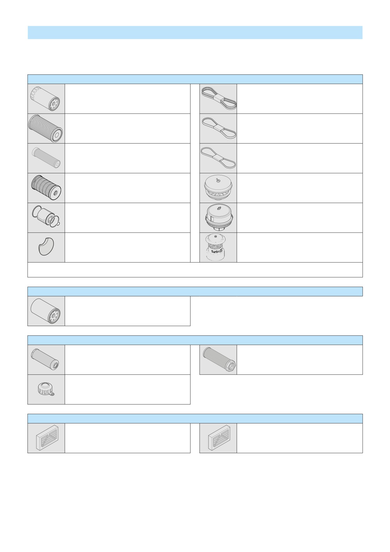
FILTERS CARTRIDGES AND BELTS
I.C. ENGINE
I.C. ENGINE OIL FILTER
ALTERNATOR BELT
Part number: 476954
Part number: 702974
Change: 500 H
DRY AIR FILTER CARTRIDGE
Part number: 563416
FAN BELT
Clean: 50 H*
Part number: 257524
Change: 500 H*
SAFETY DRY AIR FILTER CARTRIDGE
COMPRESSOR BELT
Part number: 563415
(OPTION AIR CONDITIONING)
Change: 1000 H*
Part number: 244237
FUEL FILTER CARTRIDGE
CYCLONIC PRE-FILTER
Part number: 605013
Part number: 224713
Change: 500 H
Clean: 10 H
FUEL PRE-FILTER
AUTOMATIC VACUUM-CLEANING PRE-FILTER (OPTION)
Part number: 706497
Part number: 226611
Change: 500 H
CLEANFIX COMPRESSOR FILTER (OPTION)
AUTOMATIC VACUUM-CLEANING PRE-FILTER (OPTION)
Part number: 781443
Part number: 223510
Change: 500 H
*: This periodicity is given for information only (see: 3 - MAINTENANCE: SERVICING SCHEDULE) for cleaning and changing.
TRANSMISSION
GEAR BOX OIL FILTER
Part number: 561749
Change: 500 H
HYDRAULIC
HYDRAULIC RETURN OIL FILTER CARTRIDGE
SUCTION STRAINER FOR HYDRAULIC OIL TANK
Part number: 236095
Part number: 224726
Change: 500 H
Clean: 1000 H
FILTER CAP FOR HYDRAULIC OIL TANK
Part number: 62415
Change: 1000 H
CAB
CAB VENTILATION FILTER (WITH AIR CONDITIONING)
CAB VENTILATION FILTER (WITHOUT AIR CONDITIONING)
Part number: 225052
Part number: 225052
Clean: 50 H
Clean: 500 H
Change: 250 H
3-6
3-7

LUBRICANTS AND FUEL
USE THE RECOMMENDED LUBRICANTS AND FUEL:
- For topping up, oils may not be miscible.
- For oil changes, MANITOU oils are perfectly appropriate.
DIAGNOSTIC ANALYSIS OF OILS
If a ser vice or maintenance contract has been organized with the dealer, a diagnostic analysis of engine, gear box and axle oils
may be requested depending on the rate of use.
(*) RECOMMENDED FUEL SPECIFICATION
Use a high-quality fuel to obtain optimal per formance of the I.C. engine.
• N590 diesel fuel type - Auto/C0/C1/C2/C3/C4
• BS2869 Class A2
• ASTM D975-91 Class 2-2DA, US DF1, US DF2, US DFA
• JIS K2204 (1992) Grades 1, 2, 3 and Special Grade 3.
I.C. ENGINE
ORGANS TO BE LUBRICATED
CAPACITY
RECOMMENDATION
PACKAGING
PART NUMBER
5 l
661706
20 l
582357
MANITOU Oil
I.C. ENGINE
11 Litres
55 l
582358
API CH4
209 l
582359
1000 l
490205
2 l
473076
Cooling liquid
5 l
470077
(protection - 30°)
20 l
470078
COOLING CIRCUIT
18,5 Litres
2 l
554002
Cooling liquid
5 l
554003
(protection - 25°)
20 l
554004
FUEL TANK
120 Litres
Diesel fuel (*)
TRANSMISSION
ORGANS TO BE LUBRICATED
CAPACITY
RECOMMENDATION
PACKAGING
PART NUMBER
1 l
62148
20 l
546332
MANITOU Oil
GEAR BOX
16,6 Litres
55 l
546217
Automatic transmission
209 l
546195
1000 l
720148
2 l
499237
MANITOU Oil
5 l
720184
ANGLE GEAR BOX
2,2 Litres
SAE80W90
20 l
546330
Mechanical transmission
55 l
546221
209 l
546220
400 g
161589
1 kg
720683
MANITOU Grease
TRANSMISSION UNIVERSAL JOINT
5 kg
554974
BLUE multi-purpose
20 kg
499233
50 kg
489670
BOOM
ORGANS TO BE LUBRICATED
RECOMMENDATION
PACKAGING
PART NUMBER
400 g
545996
MANITOU Grease
BOOM PADS
1 kg
161590
BLACK multi-purpose
5 kg
499235
400 g
161589
1 kg
720683
MANITOU Grease
GREASING OF THE BOOM
5 kg
554974
BLUE multi-purpose
20 kg
499233
50 kg
489670
3-8

HYDRAULIC
ORGANS TO BE LUBRICATED
CAPACITY
RECOMMENDATION
PACKAGING
PART NUMBER
5 l
545500
MANITOU Oil
20 l
582297
HYDRAULIC OIL TANK
128 Liters
Hydraulic ISO VG 46
55 l
546108
209 l
546109
BRAKE
ORGANS TO BE LUBRICATED
RECOMMENDATION
PACKAGING
PART NUMBER
MANITOU Oil
BRAKE CIRCUIT
1 l
490408
Mineral brake fluid
CAB
ORGANS TO BE LUBRICATED
RECOMMENDATION
PACKAGING
PART NUMBER
400 g
161589
1 kg
720683
MANITOU Grease
CAB DOOR
5 kg
554974
BLUE multi-purpose
20 kg
499233
50 kg
489670
1 l
490402
WINDSCREEN WASHER TANK
Windscreen washer fluid
5 l
486424
FRONT AXLE
ORGANS TO BE LUBRICATED
CAPACITY
RECOMMENDATION
PACKAGING
PART NUMBER
5 l
545976
MANITOU Oil
20 l
582391
FRONT AXLE DIFFERENTIAL
7,3 Liters
Special immersed brakes
209 l
546222
1000 l
720149
2 l
499237
MANITOU Oil
5 l
720184
FRONT WHEELS REDUCERS
0,75 Liter
SAE80W90
20 l
546330
Mechanical transmission
55 l
546221
209 l
546220
400 g
545996
MANITOU Grease
FRONT WHEEL REDUCING GEAR PIVOTS
1 kg
161590
BLACK multi-purpose
5 kg
499235
REAR AXLE
ORGANS TO BE LUBRICATED
CAPACITY
RECOMMENDATION
PACKAGING
PART NUMBER
5 l
545976
MANITOU Oil
20 l
582391
REAR AXLE DIFFERENTIAL
7,3 Liters
Special immersed brakes
209 l
546222
1000 l
720149
2 l
499237
MANITOU Oil
5 l
720184
REAR WHEELS REDUCERS
0,75 Liter
SAE80W90
20 l
546330
Mechanical transmission
55 l
546221
209 l
546220
400 g
545996
REAR WHEEL REDUCING GEAR PIVOTS
MANITOU Grease
1 kg
161590
REAR AXLE OSCILLATION
BLACK multi-purpose
5 kg
499235
CHASSIS
ORGANS TO BE LUBRICATED
RECOMMENDATION
PACKAGING
PART NUMBER
400 g
161589
STABILIZERS
1 kg
720683
MANITOU Grease
MT 1030 S Série 4-E3
5 kg
554974
BLUE multi-purpose
MT 1030 S Turbo Série 4-E3
20 kg
499233
50 kg
489670
3-9

SERVICING SCHEDULE
(1): MANDATORY 500 HOUR OR 6 MONTH SERVICE
This service must be carried out after approximately the first 500 hours of operation or within the 6 months following the start-up of the machine
(whichever occurs first).
A = ADJUST, C = CHECK, G = GREASE, N = CLEAN,
PAGE
P = BLEED, R = REPLACE, V = DRAIN
(1)
I.C. ENGINE
I.C. engine oil level
3-12
C
C
<<<
<<<
<<<
<<<
<<<
<<<
Cooling liquid level
3-12
C
C
<<<
<<<
<<<
<<<
<<<
<<<
Fuel level
3-12
C
C
<<<
<<<
<<<
<<<
<<<
<<<
Fuel pre-filter
3-13
C
C
<<<
<<<
<<<
<<<
<<<
<<<
Cyclonic pre-filter
3-13
N
N
<<<
<<<
<<<
<<<
<<<
<<<
Dr y air filter cartridge
3-16/27
R
C/N
<<<
R
<<<
<<<
<<<
Radiator cores
3-16
N
N
<<<
<<<
<<<
<<<
<<<
Condenser core (OPTION Air conditioning)
3-16
C/N
C/N
<<<
<<<
<<<
<<<
<<<
Fan belt tension
3-22
A
C/A
<<<
<<<
<<<
<<<
Alternator/crankshaft belt tension
3-22
A
C/A
<<<
<<<
<<<
<<<
Compressor belt tension (OPTION Air conditioning)
3-23
A
C/A
<<<
<<<
<<<
<<<
I.C. engine oil
3-26
V
V
<<<
<<<
<<<
I.C. engine oil filter
3-26
R
R
<<<
<<<
<<<
Fuel pre-filter
3-27
R
R
<<<
<<<
<<<
Fuel filter
3-28
R
R
<<<
<<<
<<<
CLEANFIX compressor filter (OPTION)
3-28
R
R
<<<
<<<
<<<
Fuel tank
3-32
N
<<<
<<<
Safety dr y air filter cartridge
3-32
R
<<<
<<<
I.C. engine silent blocks
C**
<<<
<<<
I.C. engine rates
C**
<<<
<<<
Valves clearances
C**
C**
<<<
<<<
Cooling liquid
3-38
V
<<<
Radiator
C**
<<<
Water pump and the thermostat
C**
<<<
Alternator and the starter motor
C**
<<<
Turbocompressor
C**
<<<
Fuel system
3-40
P
TRANSMISSION
Oil levelgear box
3-13
C
C
<<<
<<<
<<<
<<<
<<<
<<<
Transmission universal joint
3-17
G
G
<<<
<<<
<<<
<<<
G/C**
Angle gear box oil level
3-23
C
C
<<<
<<<
<<<
<<<
Gear box oil filter
3-29
R
R
<<<
<<<
<<<
Gear box oil
3-33
V
V
<<<
<<<
Gear box sump strainer
3-33
N
N
<<<
<<<
Angle gear box oil
3-34
V
V
<<<
<<<
Silentblocks in the gear box
C**
<<<
<<<
Gear box controls
C**
<<<
<<<
Gear box pressures
C**
<<<
Converter pressure
C**
<<<
TYRES
Tyres pressure
3-13
C
C
<<<
<<<
<<<
<<<
<<<
<<<
Wheel nuts torque
3-13
C
C
<<<
<<<
<<<
<<<
<<<
<<<
Condition of wheels and tyres
C**
<<<
<<<
Wheel
3-40
R
BOOM
Boom pads
3-14
G*
<<<
<<<
<<<
<<<
<<<
<<<
Boom
3-18
G
G
<<<
<<<
<<<
<<<
<<<
Boom pads wear
C**
<<<
<<<
Condition of boom unit
C**
<<<
Bearings and articulation rings
C**
<<<
HYDRAULIC
Hydraulic oil level
3-19
C
C
<<<
<<<
<<<
<<<
<<<
Hydraulic return oil filter cartridge
3-29
R
R
<<<
<<<
<<<
Hydraulic oil
3-34
V
<<<
<<<
Suction strainer for hydraulic oil tank
3-34
N
<<<
<<<
Filter cap for hydraulic oil tank
3-34
R
<<<
<<<
Speeds of hydraulic movements
C**
<<<
<<<
Hydraulic pump pipe filter
N**
<<<
<<<
Condition of hoses and flexible pipes
C**
<<<
<<<
Condition of cylinders (leakage, shafts)
C**
<<<
<<<
Hydraulic circuit pressures
C**
<<<
Hydraulic circuit outputs
C**
<<<
Hydraulic oil tank
N**
<<<
3-10

A = ADJUST, C = CHECK, G = GREASE, N = CLEAN,
PAGE
P = BLEED, R = REPLACE, V = DRAIN
(1)
BRAKE
Brake oil level
3-19
C
C
<<<
<<<
<<<
<<<
<<<
Parking brake
3-23
C/A
C/A
<<<
<<<
<<<
<<<
Parking brake lever mechanism
3-29
G
G
<<<
<<<
<<<
Parking brake mechanism on the transmission
G**
G**
<<<
<<<
<<<
Brake oil
V**
<<<
<<<
Brake system
P**
<<<
<<<
Brake system pressure
C**
<<<
<<<
Brake
A**
<<<
<<<
STEERING
Steering
C**
<<<
Steering swivel joints
C**
CAB
Windscreen washer liquid level
3-20
C
C
<<<
<<<
<<<
<<<
<<<
Cab door
3-20
G
G
<<<
<<<
<<<
<<<
<<<
Cab ventilation filter (OPTION Air conditioning)
3-20/24
R
N
R
<<<
<<<
<<<
<<<
Heating block non-return valve
3-24
N
N
<<<
<<<
<<<
<<<
Cab ventilation filters
3-30
N
N
<<<
<<<
<<<
Seat belt
3-35
C
<<<
<<<
Condition of the rear view mirrors
C**
<<<
<<<
Structure
C**
<<<
<<<
Air conditioning (OPTION)
3-39
C
<<<
ELECTRICITY
Longitudinal stability alarm device
C**
<<<
<<<
Condition of wiring harness and cables
C**
<<<
<<<
Lights and signals
C**
<<<
<<<
Warning indicators
C**
<<<
<<<
Front headlights
3-41
A
FRONT AXLE
Front wheels reducers pivots
3-21
G
G
<<<
<<<
<<<
<<<
G/C**
Front axle differential oil level
3-24
C
C
<<<
<<<
<<<
<<<
Front wheels reducers oil level
3-24
C
C
<<<
<<<
<<<
<<<
Front axle differential oil
3-30
V
V
<<<
<<<
<<<
Front wheels reducers oil
3-36
V
V
<<<
<<<
Wear of front axle brake discs
C**
Front wheels reducers universal joint
C**
Front wheels reducers clearance
C**
REAR AXLE
Rear wheels reducers pivots
3-21
G
G
<<<
<<<
<<<
<<<
G/C**
Rear axle oscillation
3-21
G
G
<<<
<<<
<<<
G/C**
<<<
Rear axle differential oil level
3-24
C
C
<<<
<<<
<<<
<<<
Rear wheels reducers oil level
3-24
C
C
<<<
<<<
<<<
<<<
Rear axle differential oil MT 732 / MT 932 / MT 1030
3-30
V
V
<<<
<<<
<<<
Rear axle differential oil MT 728 / MT 928
3-35
V
V
<<<
<<<
Rear wheels reducers oil
3-36
V
V
<<<
<<<
Wearing of rear axle brake discs
C**
Rear wheels reducers universal joint
C**
Rear wheels reducers clearance
C**
CHASSIS
Stabilizers
3-21
G
G
<<<
<<<
<<<
<<<
<<<
Structure
C**
<<<
<<<
Bearings and articulation rings
C**
<<<
ATTACHMENTS
Forks wear
C**
C**
<<<
<<<
<<<
Attachment carriage
C**
<<<
<<<
Condition of attachments
C**
<<<
<<<
LIFT TRUCK
Tow the lift truck
3-41
XXX
Sling the lift truck
3-41
XXX
Transport the lift truck on a platform
3-43
XXX
(*): Ever y 10 hours during the first 50 hours, then once at 250 hours.
(**): Consult your dealer.
3-11

A - DAILY OR EVERY 10 HOURS SERVICE
A1 - I.C. ENGINE OIL LEVEL
A1
CHECK
Place the lift truck on level ground with the I.C. engine stopped, and let the oil drain into
2
the sump.
- Open the I.C. engine bonnet.
- Remove the dipstick 1 (fig. A1).
- Clean the dipstick and check the correct level between the two notches.
1
- If necessar y, add oil (see: 3 - MAINTENANCE: LUBRICANTS AND FUEL) by the filler port 2
(fig. A1).
- Check visually that there is no leakage or seepage of oil in the I.C. engine.
A2 - COOLING LIQUID LEVEL
A2
CHECK
Place the lift truck on level ground with the I.C. engine stopped, and allow the I.C. engine
2
to cool.
3
- Open the I.C. engine bonnet.
- Check the correct level in the middle of gauge 1 (fig. A2).
- If necessar y, add cooling liquid (see: 3 - MAINTENANCE: LUBRICANTS AND FUEL).
- Slowly turn the cap of the radiator 2 (fig. A2) up to the safety stop.
1
- Allow the pressure and the steam to escape.
- Press down and turn the cap so as to release it.
- Add cooling liquid via filler port 3 (fig. A2) up to the middle of gauge 1 (fig. A2).
MT 7.. / MT 9.. / MT 1030 S
- Lubricate slightly the filler neck in order to facilitate the setting and the removal of the
radiator cap.
A2
- Check visually that there is no leakage in the radiator and pipes.
To avoid any risk of spraying or burning, wait until the I.C. engine has cooled down before removing
2
the cooling circuit filler plug. If the cooling liquid is very hot, add only hot cooling liquid (80°C). In an
emergency, you can use water as a cooling liquid, then change the cooling circuit liquid as soon as
3
possible (see: 3 - MAINTENANCE: F1 - COOLING LIQUID).
1
MT 1030 S Turbo
A3 - FUEL LEVEL
A3
CHECK
Keep the fuel tank full, to reduce as much as possible any condensation due to the
1
atmospheric conditions.
2
- Remove cap 1 (fig. A3).
- Fill the fuel tank with clean fuel (see: 3 - MAINTENANCE: LUBRICANTS AND FUEL), filtered
through a strainer or a clean, lint free cloth, through filler port 2 (fig. A3).
- Put the cap back 1 (fig. A3).
- Check visually that there is no leakage in the tank and pipes.
Never smoke or approach with a flame during filling operations or when the tank is open. Never refill
while I.C. engine is running.
The fuel tank is degassed via the filler plug. When changing it, always use an original part, with degassing
hole.
NOTE: A locking tank cap is available as an OPTION.
3-12

A4 - FUEL PRE-FILTER
A4
CHECK
- Open the I.C. engine bonnet.
- Check for the presence of water in the pre-filter bowl 1 (fig. A4) and empty it out if
necessar y.
- Place a receptacle under the drain plug 2 (fig. A4) and loosen it in two to three thread turns.
- Allow the diesel fuel to flow out until it is free from impurities and water.
- Retighten the drain plug while the diesel fuel is flowing out.
1
2
A5 - CYCLONIC PRE-FILTER
A5
CLEAN
1
2
The cleaning inter val is given as a guide, however the pre-filter must be emptied as soon
as impurities reach the MAXI level on the tank.
- Loosen nut 1 (fig. A5), remove cover 2 (fig. A5) and empty the tank.
- Clean the pre-filter unit with a clean dr y cloth and reassemble the unit.
When cleaning, take care not to let impurities into the dry air filter.
A6 - GEAR BOX OIL LEVEL
A6
CHECK
Park the lift truck on level ground with the boom raised, the I.C. engine cold and stopped.
1
Carr y out the control within 5 minutes of the I.C. engine being stopped.
- Remove the plastic cap 1 (fig. A6).
2
- Remove the dipstick 2 (fig. A6).
- Wipe the dipstick and check the correct level between the two MIN and MAX marks.
- If necessar y, add oil (see: 3 - MAINTENANCE: E3 - GEAR BOX OIL).
- Check visually that there is no leakage or seepage of oil in the transmission.
A7 - TYRES PRESSURE AND WHEEL NUTS TORQUE
CHECK
- Check the condition of the tyres, to detect cuts, protuberances, wear, etc.
- Check the torque load of the wheel nuts. Non compliance with this instruction can cause damage and rupture to the wheel bolts
and distortion to the wheels.
Wheel nuts tightening torque
• Front tyres: 630 N.m ± 15 %
• Rear tyres: 630 N.m ± 15 %
- Check and adjust the tyre pressures if necessar y (see: 2 - DESCRIPTION: FRONT AND REAR TYRES).
Check that the air hose is correctly connected to the tyre valve before inflating and keep all persons at a distance during inflation. Respect the
recommended tyre pressures given.
NOTE: There is an OPTIONAL wheel toolkit and anti-puncture kit.
3-13
A8 - BOOM PADS
A8
CLEAN - GREASE
To be carried out ever y 10 hours during the first 50 hours ser vice, then once at 250
hours.
- Extend the boom completely.
- With a brush, apply a coat of grease (see: 3 - MAINTENANCE: LUBRICANTS AND FUEL) on
the 4 sides of the telescope(s) (fig. A8).
- Telescope the boom several times in order to spread the coat of grease evenly.
- Remove the surplus of grease.
If the lift truck is used in an abrasive environment (dust, sand, coal…) Use lubricating varnish (MANITOU
reference: 483536). In this respect, consult your dealer.
MT 732 Série D-E3
MT 932 Série D-E3
MT 1030 S Série 4-E3
MT 1030 S Turbo Série 4-E3
NOTE: A boom sealing kit is available as an OPTION.
3-14
3-15

B - EVERY 50 HOURS SERVICE
Carry out the operations described previously as well as the following operations.
B1 - DRY AIR FILTER CARTRIDGE
CHECK - CLEAN
In case of use in a heavily dust laden atmosphere, there are pre-filtration cartridges (see: 3 - MAINTENANCE: FILTERS CARTRIDGES
AND BELTS). Also, the checking and cleaning periodicity of the cartridge must be reduced.
If the clogging indicator light comes on, this operation must be carried out as quickly as possible (1 hour maximum). The cartridge must not be cleaned
more than seven times, after which the cartridge must be changed. Never use the lift truck without an air filter or with a damaged air filter.
- For the disassembly and reassembly of the cartridge, see: 3 - MAINTENANCE: D3 - DRY AIR FILTER CARTRIDGE.
- Clean the filter cartridge using a compressed air jet (max. pressure 3 bar) directed from the top to the bottom and from the inside
towards the outside at a minimum distance of 30 mm from the cartridge wall.
- Cleaning is completed when there is no more dust on the cartridge.
Respect the safety distance of 30 mm between the air jet and the cartridge to avoid tearing or making a hole in the cartridge. The cartridge must
not be blown anywhere near the air filter box. Never clean the cartridge by tapping it against a hard surface. Your eyes must be protected during this
intervention.
- Clean the cartridge seal sur faces with a damp, clean lint-free cloth and grease with a silicone lubricant (MANITOU reference:
479292).
- Check visually the outer condition of the air filter and its mounts. Verify the condition of the hoses and their mounts also.
Never clean the dry air filter cartridge by washing it in liquid. Do not clean by any means the safety cartridge located inside the filter cartridge, change
it for a new one if it is clogged or damaged.
B2 - RADIATOR CORES
B2
CLEAN
In a polluting atmosphere, clean the radiator core every day. Do not use a water jet or high-pressure
steam as this could damage the radiator fins.
- Open the I.C. engine bonnet.
- If necessar y, clean the suction grid on the engine hood.
- Using a soft cloth, clean the radiator cores in order to remove as much dirt as possible.
- Clean the cores using a compressed air jet aimed in the same direction as the cooling
air flow (fig. B2).
- Clean with the fan running for best results.
MT 732 Série D-E3
MT 932 Série D-E3
MT 1030 S Série 4-E3
MT 1030 S Turbo Série 4-E3
NOTE: An OPTIONAL straw defector and self-cleaning fan can also be fitted.
B3 - CONDENSER CORE (OPTION AIR CONDITIONING)
B3
CHECK - CLEAN
1
In a polluting atmosphere, clean the radiator core every day. Do not use a water jet or high-pressure
steam as this could damage the condenser fins.
- Remove the protective grid 1 (fig. B3) and clean it if necessar y.
- Visually check whether the condenser 2 (fig. B3) is clean and clean it if necessary.
- Clean the condenser using a compressed air jet aimed in the same direction as the air
2
flow (fig. B3).
NOTE: So as to enhance the cleaning, carr y out this operation with the fans running.
3-16

B4 - TRANSMISSION UNIVERSAL JOINT
B4/1
1
GREASE
- Clean and lubricate the following points with grease (see: 3 - MAINTENANCE: LUBRICANTS
AND FUEL) and remove the surplus of grease.
1 - Lubricators of the universal joint I.C. engine/Angle gear box
(2 lubricators) (fig. B4/1).
2 - Lubricators of the universal joint Transmission/Front axle
(3 lubricators) (fig. B4/2).
1
3 - Lubricators of the universal joint Transmission/Rear axle
(3 lubricators) (fig. B4/3).
B4/2
2
2
2
B4/3
3
3
3
3-17

B5 - BOOM
GREASE
To be carried out weekly, if the lift truck has been operated for less than 50 hours during the week.
In the event of prolonged use in an extremely dusty or oxidising atmosphere, reduce this interval to 10 working hours or every day.
- Clean and lubricate the following points with grease (see: 3 - MAINTENANCE: LUBRICANTS AND FUEL) and remove the surplus
of grease.
B5/1
1 - Lubricators of the boom axle (2 lubricators) (fig. B5/1).
2 - Lubricators of the carriage axle (2 lubricators) (fig. B5/2).
3 - Lubricator of the tilt cylinder foot axle (1 lubricator) (fig. B5/3).
4 - Lubricator of the tilt cylinder head axle (1 lubricator) (fig. B5/4).
1
1
5 - Lubricator of the lifting cylinder foot axle (1 lubricator) (fig. B5/5).
6 - Lubricator of the lifting cylinder head axle (1 lubricator) (fig. B5/6).
7 - Lubricator of the compensation cylinder foot axle (1 lubricator) (fig. B5/5).
8 - Lubricator of the compensation cylinder head axle (1 lubricator) (fig. B5/7).
B5/2
B5/3
B5/4
2
2
3
4
B5/5
B5/6
B5/7
8
5
7
6
3-18

B6 - HYDRAULIC OIL LEVEL
B6/1
CHECK
Place the lift truck on level ground with the I.C. engine stopped, and the boom retracted
and lowered as far as possible.
- Refer to gauge 1 (fig. B6/1).
- The oil level is correct when it is at the level of the red point.
1
- If necessar y, add oil (see: 3 - MAINTENANCE: LUBRICANTS AND FUEL).
- Remove cap 2 (fig. B6/2).
- Add oil by filler port 3 (fig. B6/2).
Use a clean funnel and clean the underside of the oil drum before filling.
- Put the cap back.
- Check visually that there is no leakage in the tank and pipes.
B6/2
Always maintain the oil level at maximum as cooling depends on the oil flowing through
2
the tank.
3
B7 - BRAKE OIL LEVEL
B7/1
CHECK
2
Place the lift truck on level ground.
- Loosen screw 1 (fig. B7/1) and remove the access panel for braking oil tank and
windscreen washer tank 2 (fig. B7/1).
- The level is correct when it is at the MAX. level in tank 3 (fig. B7/2)
- If necessar y, add oil (see: 3 - MAINTENANCE: LUBRICANTS AND FUEL) by the filler port.
1
- Pivot the tank 3 (fig. B7/2) to access the filler cap 4 (fig. B7/2).
- Check visually that there is no leakage in the tank and pipes.
If the braking oil level is abnormally low, consult your dealer.
B7/2
4
3
3-19
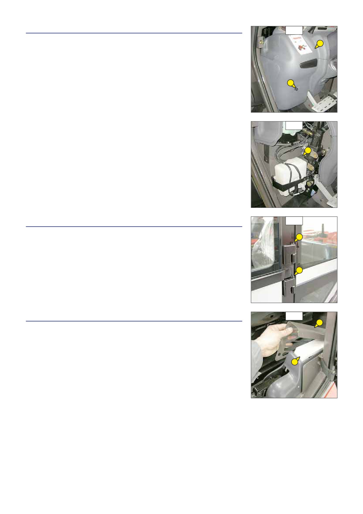
B8 - WINDSCREEN WASHER LIQUID LEVEL
B8/1
CHECK
2
- Loosen screw 1 (fig. B8/1) and remove the access panel for braking oil tank and
windscreen washer tank 2 (fig. B8/1).
- Check visually the level.
- If necessar y add windscreen washer liquid (see: 3 - MAINTENANCE: LUBRICANTS AND
FUEL) by filler port 3 (fig. B8/2).
1
B8/2
3
B9
B9 - CAB DOOR
GREASE
1
- Clean and lubricate the points 1 (4 lubricators) (fig. B9) with grease (see: 3 - MAINTENANCE:
LUBRICANTS AND FUEL) and remove the surplus of grease.
1
B10 - CAB VENTILATION FILTER (OPTION AIR CONDITIONING)
B10
1
CLEAN
- Lift up protective casing 1 (fig. B10).
- Lift out cabin ventilation filter 2 (fig. B10).
- Clean the filter with a compressed air jet.
- Check its condition and change if necessar y (see: 3 - MAINTENANCE: FILTERS CARTRIDGES
2
AND BELTS).
- Refit the filter and protective casing.
3-20
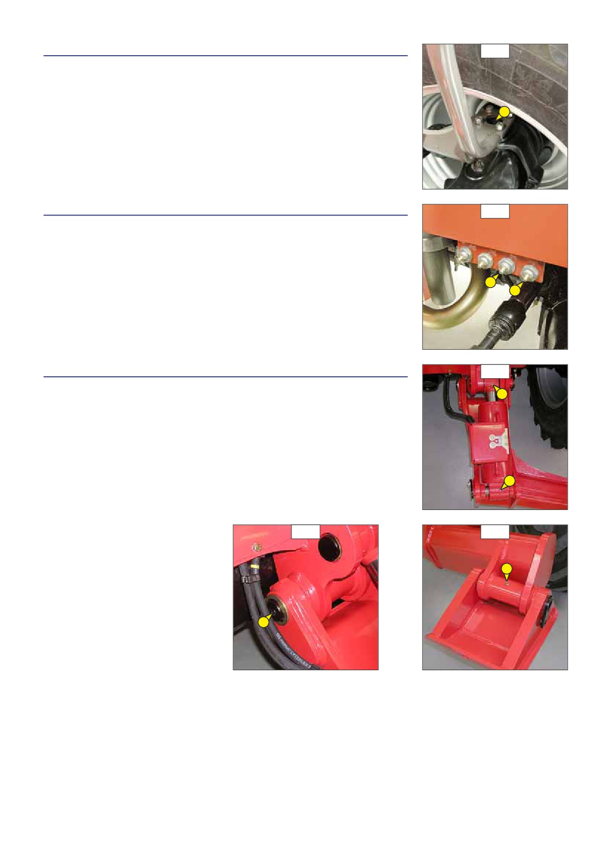
B11 - FRONT AND REAR WHEEL REDUCER PIVOTS
B11
GREASE
- Clean and lubricate the points 1 (8 lubricators) (fig. B11) with grease (see: 3 - MAINTENANCE:
LUBRICANTS AND FUEL) and remove the surplus of grease.
1
B12 - REAR AXLE OSCILLATION
B12
GREASE
- Clean and lubricate the points 1 (2 lubricators) (fig. B12) with grease (see: 3 - MAINTENANCE:
LUBRICANTS AND FUEL) and remove the surplus of grease.
1
1
B13 - STABILIZERS
B13/1
GREASE
MT 1030 S Série 4-E3
1
MT 1030 S Turbo Série 4-E3
- Clean and lubricate the following points with grease (see: 3 - MAINTENANCE: LUBRICANTS
AND FUEL) and remove the surplus of grease.
1 - Nipples on stabilizer actuator shafts (4 nipples) (fig. B13/1).
2 - Nipples on stabilizer actuator shafts (4 nipples) (fig. B13/2 et B13/3).
1
B13/2
B13/3
2
2
3-21

C - EVERY 250 HOURS SERVICE
Carry out the operations described previously as well as the following operations.
C1 - FAN BELT TENSION
C1/1
CHECK - ADJUST
3
2
- Open the I.C. engine bonnet.
- Check the belt for signs of wear and cracks and change if necessar y (see: 3 - MAINTENANCE:
FILTERS CARTRIDGES AND BELTS).
- Loosen screw 1 (fig. C1/1) on the tension pulley.
- Loosen lock nut 2 (fig. C1/1 and C1/2) and screw 3 (fig. C1/1 and C1/2).
1
- Tighten the screw 2 (fig. C1/1 and C1/2) until the belt is as close as possible to the
groove of the pulley 4 (fig. C1/1).
- Make a mark on the head of screw 3 (fig. C1/1 and C1/2) and tighten, turning it 5
times.
4
- Tighten the lock nut 2 (fig. C1/1 and C1/2).
- Retighten screw 1 (fig. C1/1) on the tension pulley.
When changing the fanbelt, tighten screw 3 (fig. C1/1 and C1/2) by one and a half turns, having allowed
C1/2
the I.C. engine to idle for 30 minutes.
3
2
C2/1
C2 - ALTERNATOR/CRANKSHAFT BELT TENSION
CHECK - ADJUST
2
- Open the I.C. engine bonnet.
- Unscrew the fastening screws 1 (fig. C2/1).
- Lay down the protective guard 2 (fig. C2/1).
- Check the belt for signs of wear and cracks and change if necessar y (see: 3 - MAINTENANCE:
1
FILTERS CARTRIDGES AND BELTS).
- Check the belt tension between the pulleys of the crankshaft and of the alternator.
- Under a normal pressure exerted with the thumb (45 N), the belt should move approximately
1
10 mm.
- Carr y out adjustments if necessar y.
- Untighten screws 3 (fig. C2/2) by two to three thread turns.
- Swivel the alternator assembly so as to obtain the belt tension required.
- Retighten screws 3 (fig. C2/2) (tightening torque 22 N.m).
C2/2
- Put the protective guard back 2 (fig. C2/1).
If the alternator belt has to be changed, check the tension again after the first 20 hours of operation.
3
3
3
3-22

C3 - COMPRESSOR BELT TENSION (OPTION AIR CONDITIONING)
C3/1
CHECK - ADJUST
- Open the I.C. engine bonnet.
2
- Unscrew the fastening screws 1 (fig. C3/1).
- Lay down the protective guard 2 (fig. C3/1).
1
- Check the belt for signs of wear and cracks and change if necessar y (see: 3 - MAINTENANCE:
1
FILTERS CARTRIDGES AND BELTS).
- Check the belt tension between the pulleys of the crankshaft and of the compressor.
1
1
- Under a normal pressure exerted with the thumb
(45 N), the tension should be
approximately 10 mm.
- Carr y out adjustments if necessar y.
- Untighten screws 3 (fig. C3/2) by two to three thread turns.
- Swivel the compressor assembly so as to obtain the belt tension required.
- Retighten screws 3 (fig. C3/2).
C3/2
- Put the protective guard back 2 (fig. C3/1).
If the compressor belt has to be changed, check the tension again after the first 20 hours of operation.
3
3
C4 - ANGLE GEAR BOX OIL LEVEL
C4
CHECK
Park the lift truck on level ground with the boom raised and the I.C. engine stopped.
1
- Remove level plug 1 (fig. C4).
- Wipe the dipstick and check the correct level between the MINI and MAXI marks.
- If necessar y, add oil (see: 3 - MAINTENANCE: E5 - ANGLE GEAR BOX OIL).
C5 - PARKING BRAKE
C5
CHECK - ADJUST
A
Place the lift truck on a slope less than 15 % with the rated load in the transport position.
1
- Check the tightening adjustment by locking the parking brake in position A (fig. C5).
- The adjustment is correct when the lift truck is held stationar y on a slope.
B
- Carr y out adjustments if necessar y.
- Press and release the brake pedal, then release the parking brake, putting it in position
B (fig. C5).
- Progressively tighten the end piece of the lever 1 (fig. C5) and recheck braking.
- Repeat the operation until the correct braking adjustment is obtained.
3-23
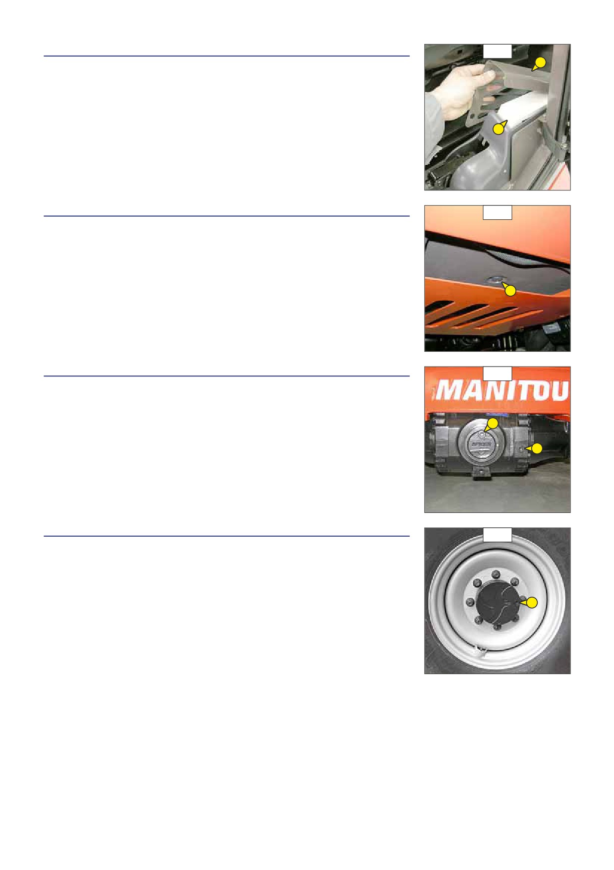
C6 - CAB VENTILATION FILTER (OPTION AIR CONDITIONING)
C6
CHANGE
1
- Lift up protective casing 1 (fig. C6).
- Lift out cabin ventilation filter
2 (fig. C6) and fit new replacement filter
(see:
3 -
MAINTENANCE: FILTERS CARTRIDGES AND BELTS).
- Refit the protective casing.
2
C7 - HEATING BLOCK NON-RETURN VALVE
C7
CLEAN
- Since non-return valve 1 (fig. C7) is located under the cab, it is possible for it to become
obstructed with spattered mud for example. Clean if necessar y.
1
C8 - FRONT AND REAR DIFFERENTIAL OIL LEVEL
C8
CHECK
Place the lift truck on level ground with the I.C. engine stopped.
2
- Remove level plug 1 (fig. C8). The oil should be flush with the edge of the hole.
- If necessar y, add oil (see: 3 - MAINTENANCE: LUBRICANTS AND FUEL) by the filler port 2
(fig. C8).
1
- Replace and tighten the level plug 1 (fig. C8) (tightening torque 34 to 49 N.m).
- Repeat this operation for the rear axle differential.
C9 - FRONT AND REAR WHEELS REDUCERS OIL LEVEL
C9
CHECK
Place the lift truck on level ground with the I.C. engine stopped.
- Check the level on each front wheel reducer.
- Place level plug 1 (fig. C9) in the horizontal position.
1
- Remove the level plug, the oil should be flush with the edge of the hole.
- If necessar y, add oil (see: 3 - MAINTENANCE: LUBRICANTS AND FUEL) by the same hole.
- Replace and tighten the level plug 1 (fig. C9) (tightening torque 34 to 49 N.m).
- Repeat this operation on each rear wheel reducer.
3-24
3-25

D - EVERY 500 HOURS SERVICE
Carry out the operations described previously as well as the following operations.
D1 - I.C. ENGINE OIL
D1/1
DRAIN
D2 - I.C. ENGINE OIL FILTER
CHANGE
1
Place the lift truck on level ground, let the I.C. engine run at idle for a few minutes, then
stop the I.C. engine.
DRAINING THE OIL
- Open the I.C. engine bonnet.
- Remove access panel 1 (fig. D1/1).
- Place a container under drain plug 2 (fig. D1/2) and unscrew the plug 3 (fig. D1/3).
- Take drain hose 4 (fig. D1/4).
- Place the end of the drain hose in the container and screw fully the union on draining port 5
(fig. D1/5).
D1/2
- Remove filler cap 6 (fig. D1/6) in order to ensure that the oil is drained properly.
Dispose of the drain oil in an ecological manner.
REPLACEMENT OF THE FILTER
- Remove I.C. engine oil filter 7 (fig. D1/3); discard the filter and the filter seal.
2
- Clean the filter bracket with a clean, lint-free cloth.
- Lightly grease the new oil filter seal and refit the oil filter (see: 3 - MAINTENANCE: FILTERS
CARTRIDGES AND BELTS) on the filter bracket.
Tighten the oil filter by hand pressure only and lock the filter in place by a quarter turn.
FILLING UP THE OIL
D1/3
- Loosen, clean and put back in place the drain hose 4 (fig. D1/4).
- Refit and tighten drain plug 3 (fig. D1/3).
- Refit access panel 1 (fig. D1/1).
- Fill up with oil (see: 3 - MAINTENANCE: LUBRICANTS AND FUEL) through filler port 8 (fig.
7
D1/6).
- Wait a few minutes to allow the oil to flow into the sump.
- Start the I.C. engine and let it run for a few minutes.
- Check for possible leaks at the drain plug and the oil filter.
- Stop the I.C. engine, wait a few minutes and check the level between the two notches on
3
dipstick 9 (fig. D1/6).
- Top up the level if necessar y.
D1/4
4
D1/5
D1/6
6
8
5
9
3-26

D3 - DRY AIR FILTER CARTRIDGE
D3
CHANGE
1
In case of use in a heavily dust laden atmosphere, there are pre-filtration cartridges, see:
3 - MAINTENANCE: FILTERS CARTRIDGES AND BELTS. Also, the checking and cleaning
periodicity of the cartridge must be reduced (up to 250 hours in a heavily laden dust
atmosphere and with pre-filtration).
Change the cartridge in a clean location, with the I.C. engine stopped. Never operate the lift truck with
2
the air filter removed or damaged.
- Open the I.C. engine bonnet.
- Loosen the bolts and remove cover 1 (fig. D3).
- Gently remove the cartridge 2 (fig. D3), taking care to avoid spilling the dust.
- Leave the safety cartridge in place.
- The following parts must be cleaned with a damp, clean lint-free cloth.
• The inside of the filter and cover.
• The inside of the filter inlet hose.
• The gasket sur faces in the filter and in the cover.
- Check pipes and connections between the air filter and the I.C. engine and the connection and state of the clogging indicator on
the filter.
- Before mounting check the state of the new cartridge (see: 3 - MAINTENANCE: FILTERS CARTRIDGES AND BELTS).
- Introduce the cartridge into the filter axis and push it in, pressing the edges and not the middle.
- Reassemble the cover, guiding the valve downwards.
D4 - FUEL PRE-FILTER
D4
CHANGE
3
2
Make sure the electrical contact on the lift truck is cut, otherwise fuel will be released if the lift pump
is on.
- Open the I.C. engine bonnet.
5
- Carefully clean the outside of the pre-filter and its holder, to prevent dust from getting into
the system.
4
- Place a container under the pre-filter and drain it using drain plug 1 (fig. D4).
- Remove bleeder screw 2 (fig. D4) in order to ensure that the oil is drained properly.
- Unscrew locking screw 3 (fig. D4).
- Remove housing 4 (fig. D4) and discard pre-filter 5 (fig. D4) and its seals.
1
- Clean the inside of the pre-filter head and the housing, using a brush immersed in clean
diesel oil.
- Refit the assembly with a new pre-filter and new seals (see: 3 - MAINTENANCE: FILTERS
CARTRIDGES AND BELTS).
- If necessar y, bleed the fuel circuit (see: 3 - MAINTENANCE: G1 - FUEL SYSTEM).
3-27
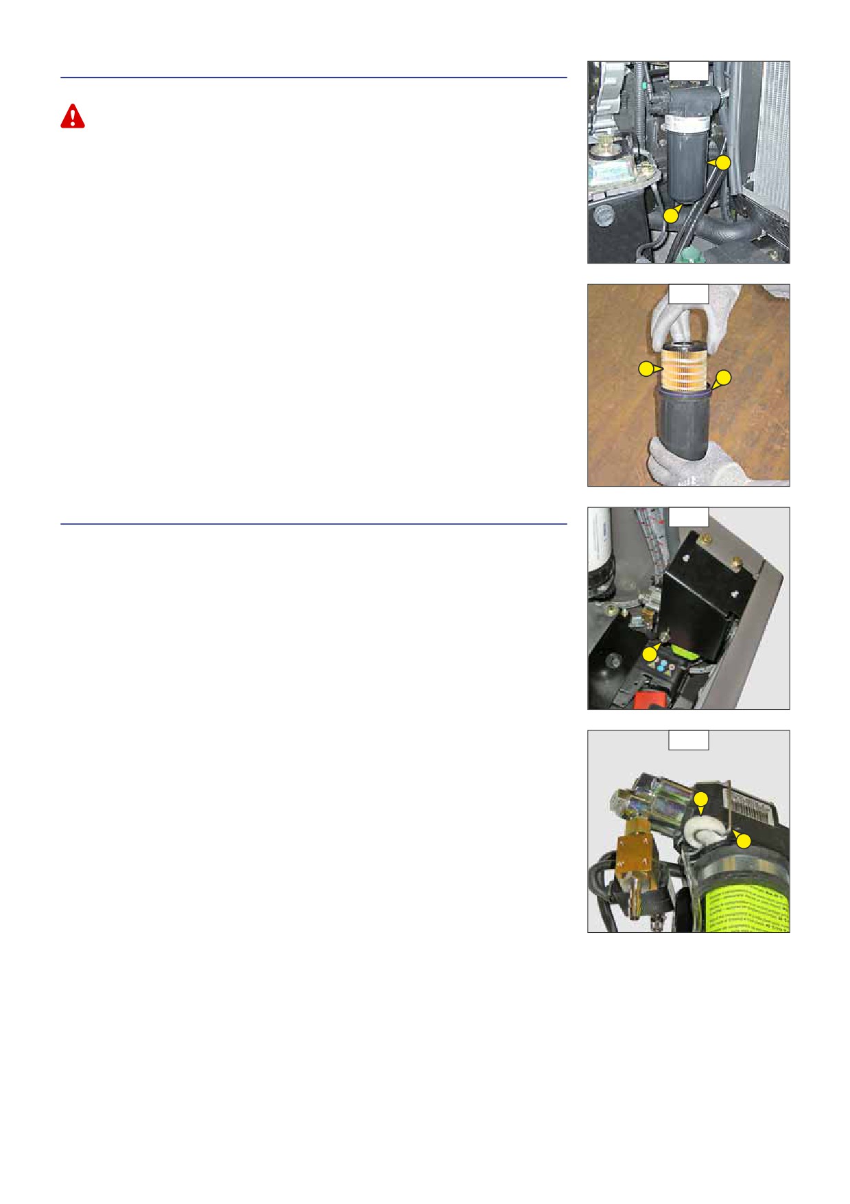
D5 - FUEL FILTER
D5/1
CHANGE
Make sure the electrical contact on the lift truck is cut, otherwise fuel will be released if the lift pump
is on.
- Open the I.C. engine bonnet.
- Carefully clean the outside of the filter and its holder, to prevent dust from getting into
2
the system.
- Place a container under the filter and drain it through drain plug 1 (fig. D5/1).
- Loosen the body of filter 2 (fig. D5/1).
1
- Remove the filter cartridge by pressing cartridge 3 (fig. D5/2) down against the pressure
of the spring and turn it to the left to extract it.
- Insert a new cartridge (see: 3 - MAINTENANCE: FILTERS CARTRIDGES AND BELTS), by
pressing cartridge 3 (fig. D5/2) down against the pressure of the spring and turn it to the
right to lock it into the body of the filter.
- Place the new seal 4 (fig. D5/2) onto the body of the filter and lightly lubricate the contact
D5/2
sur face of the seal using clean motor oil.
- Refit the body of the filter onto its holder, hand-tighten it only and lock it with a
quarter-turn.
- Close drain plug 1 (fig. D5/1) and remove the container.
3
- Before starting the I.C. engine, leave the ignition on for three minutes on the lift truck, to
4
give the lift pump time to release air from the filter.
- Start up the I.C. engine and make sure there is no leakage.
- If necessar y, bleed the fuel circuit (see: 3 - MAINTENANCE: G1 - FUEL SYSTEM).
D6 - CLEANFIX COMPRESSOR FILTER (OPTION)
D6/1
CHANGE
-Open the I.C. engine bonnet.
- Remove compressor securing nut 1 (fig. D6/1).
- Remove clip 2 (fig. D6/2).
- Replace filter 3 (fig. D6/2) with a new one (see: 3 - MAINTENANCE: FILTERS CARTRIDGES
AND BELTS) and correctly refit clip 2 (fig. D6/2).
- Refit the compressor securing nut 1 (fig. D6/1).
1
D6/2
3
2
3-28
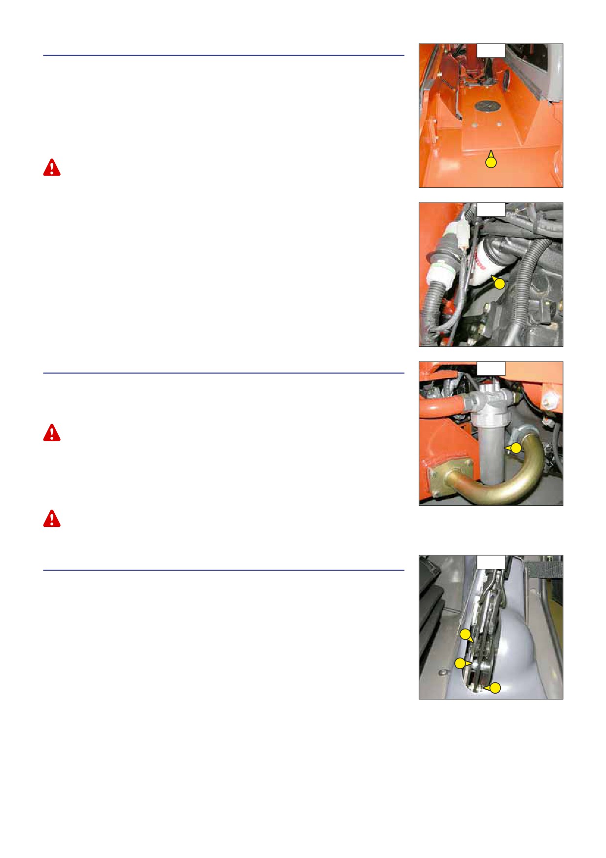
D7 - GEAR BOX OIL FILTER
D7/1
CHANGE
- Remove the cover plate 1 (fig. D7/1).
- Unscrew and discard gear box oil filter 2 (fig. D7/2).
- Carefully clean the filter head with a clean, lint-free cloth.
- Slightly lubricate the new seal and fit the seal on the filter.
- Fill up the new gear box oil filter (see: 3 - MAINTENANCE: FILTERS CARTRIDGES AND
BELTS) with oil (see: 3 - MAINTENANCE: LUBRICANTS AND FUEL).
- Refit the filter, making sure that the seal is correctly positioned and tightened.
1
Tighten the gear box oil filter by hand pressure only and lock the filter in place by a quarter turn.
- Put back the cover plate 1 (fig. D7/1).
D7/1
2
D8 - HYDRAULIC RETURN OIL FILTER CARTRIDGE
D8
CHANGE
Stop the I.C. engine and remove the pressure from the circuits by acting on the hydraulic
controls.
Thoroughly clean the outside of the filter and its surroundings before any intervention in order to prevent
any risk of polluting the hydraulic circuit.
1
- Place a container under hydraulic drain filter 1 (fig. D8).
- Unscrew the body of the filter.
- Remove the hydraulic return oil filter cartridge and fit new replacement cartridge (see:
3 - MAINTENANCE: FILTERS CARTRIDGES AND BELTS).
- Make sure that the cartridge is correctly positioned and refit the body of the filter.
Tighten the body of the filter by hand pressure only and lock the body of the filter in place by a quarter
turn.
D9 - PARKING BRAKE LEVER MECHANISM
D9
GREASE
- Clean and grease articulation axles 1 (fig. D9) with grease (see: 3 - MAINTENANCE:
LUBRICANTS AND FUEL).
1
1
1
3-29

D10 - CAB VENTILATION FILTER
D10
CLEAN
1
- Remove protective casing 1 (fig. D10).
- Lift out cabin ventilation filter 2 (fig. D10).
- Clean the filter using a compressed air jet.
- Check its condition and change if necessar y (see: 3 - MAINTENANCE: FILTERS CARTRIDGES
AND BELTS).
2
- Refit the filter and protective casing.
D11 - FRONT AXLE DIFFERENTIAL OIL
D11
DRAIN
Place the lift truck on level ground with the I.C. engine stopped and the differential oil still
warm.
3
Dispose of the drain oil in an ecological manner.
2
- Place a container under drain plugs 1 (fig. D11) and unscrew the plugs.
- Remove level plug 2 (fig. D11) and filler plug 3 (fig. D11) in order to ensure proper
emptying.
1
1
1
- Refit and tighten drain plugs 1 (fig. D11) (tightening torque 34 to 49 N.m).
- Fill up with oil (see: 3 - MAINTENANCE: LUBRICANTS AND FUEL) through filler port 3 (fig. D11).
- The level is correct when the oil level is flush with the edge of port 2 (fig. D11).
- Check for any possible leaks at the drain plugs.
- Refit and tighten level cap 2 (fig. D11) (tightening torque 34 to 49 Nm) and filler port 3
(fig. D11) (tightening torque 34 to 49 N.m).
D12 - REAR AXLE DIFFERENTIAL OIL
D12
DRAIN
MT 732 Série D-E3
3
MT 932 Série D-E3
MT 1030 S Série 4-E3
2
MT 1030 S Turbo Série 4-E3
Place the lift truck on level ground with the I.C. engine stopped and the differential oil still
warm.
1
Dispose of the drain oil in an ecological manner.
- Place a container under drain plugs 1 (fig. D12) and unscrew the plugs.
1
1
- Remove level plug 2 (fig. D12) and filler plug 3 (fig. D12) in order to ensure proper
emptying.
- Refit and tighten drain plugs 1 (fig. D12) (tightening torque 34 to 49 N.m).
- Fill up with oil (see: 3 - MAINTENANCE: LUBRICANTS AND FUEL) through filler port 3 (fig. D12).
- The level is correct when the oil level is flush with the edge of port 2 (fig. D12).
- Check for any possible leaks at the drain plugs.
- Refit and tighten level plug 2 (fig. D12) (tightening torque 34 to 49 N.m) and filler plug 3 (fig. D12) (tightening torque 34 to 49 N.m).
3-30
3-31

E - EVERY 1000 HOURS SERVICE
Carry out the operations described previously as well as the following operations.
E1 - FUEL TANK
E1/1
CLEAN
While carrying out these operations, do not smoke or work near a flame.
Place the lift truck on level ground with the I.C. engine stopped.
- Inspect the parts susceptible to leaks in the fuel circuit and in the tank.
1
- In the event of a leak, contact your dealer.
Never try to carry out a weld or any other operation by yourself, this could provoke an explosion or a
fire.
- Place a container under drain plug 1 (fig. E1/1) and unscrew the plug.
- Remove filling plug 2 (fig. E1/2) in order to ensure that the oil is drained properly.
- Rinse out with ten litres of clean diesel through filler port 3 (fig. E1/2).
- Refit and tighten the drain plug (tightening torque 29 to 39 N.m).
E1/2
- Fill the fuel tank with clean diesel filtered through the filler port.
- Refit the filling cap.
2
3
E2 - SAFETY DRY AIR FILTER CARTRIDGE
CHANGE
E2
- For the disassembly and reassembly of the dr y air filter cartridge, see: 3 - MAINTENANCE:
D3 - AIR FILTER CARTRIDGE.
- Gently remove the dr y air filter safety cartridge 1 (fig. E2), taking care to avoid spilling
the dust.
- Clean the gasket sur face on the filter with a damp, clean lint-free cloth.
1
- Before mounting, check the state of the new safety cartridge (see: 3 - MAINTENANCE:
FILTERS AND BELTS).
- Introduce the cartridge into the filter axis and push it in, pressing the edges and not the
middle.
NOTE: The periodicity for changing the safety cartridge is given for information only. It must
be changed for ever y two changes of the dr y air filter cartridge.
3-32

E3 - GEAR BOX OIL
E3/1
DRAIN
E4 - GEAR BOX SUMP STRAINER
CLEAN
Place the lift truck on level ground with the I.C. engine stopped, the gear box oil still
1
warm.
DRAINING THE OIL
- Place a container under drain plug 1 (fig. E3/1) and under cover 2 (fig. E3/2) and unscrew
the drain plug.
- Remove cover plate 3 (fig. E3/3).
- Remove dipstick 4 (fig. E3/4) and unscrew filling plug 5 (fig. E3/4) in order to ensure that
the oil is drained properly.
E3/2
Dispose of the drain oil in an ecological manner.
CLEANING THE STRAINER
- Remove cover 2 (fig. E3/2) and set aside the O-ring joint and sealing washer.
2
- Allow the rest of the oil to drain away.
- Remove and clean the strainer using a compressed air jet.
- Clean the magnetic section on the plate.
- Refit the assembly and tighten up plate 2 (fig. E3/2) (tightening torque 18 to 31 N.m).
FILLING UP THE OIL
- Refit and tighten drain plug 1 (fig. E3/1) (tightening torque 34 to 54 N.m).
- Fill up with oil (see: 3 - MAINTENANCE: LUBRICANTS AND FUEL) by filler port 5 (fig. E3/4)
and refit the filler cap.
- Start the I.C. engine and let it run for a few minutes.
E3/3
- Check any possible leaks from the drain plug or cover.
- Stop the I.C. engine, and within 5 minutes of the I.C. engine being stopped, check on the
dipstick 4 (fig. E3/4) the correct level between the two MIN and MAX. marks.
- Top up the level if necessar y.
- Put back the cover plate 3 (fig. E3/3).
3
E3/4
5
4
3-33

E5 - ANGLE GEARBOX OIL
E5/1
DRAIN
Place the lift truck on level ground with the I.C. engine stopped, the angle gear box oil still
warm.
- Place a container under drain plug 1 (fig. E5/1) and unscrew the plug.
1
- Remove dipstick 2 (fig. E5/2) and unscrew filler cap 3 (fig. E5/2) in order to ensure that
the oil is drained properly.
Dispose of the drain oil in an ecological manner.
- Refit and tighten drain plug 1 (fig. E5/1) (tightening torque 20 to 29 N.m).
- Fill up with oil (see: 3 - MAINTENANCE: LUBRICANTS AND FUEL) by filler port 3 (fig. E5/2)
and refit the filler cap.
- Check the correct level between the MINI and MAX. marks on dipstick 2 (fig. E5/2).
E5/2
- Check for any possible leaks at the drain plug.
2
3
E6 - HYDRAULIC OIL
E6/1
DRAIN
E7 - SUCTION OIL STRAINER FOR HYDRAULIC OIL TANK
CLEAN
E8 - FILTER CAP FOR HYDRAULIC OIL TANK
CHANGE
1
Place the lift truck on level ground with the I.C. engine stopped and telescope boom
retracted and lowered as far as possible.
1
Before any intervention, thoroughly clean the area surrounding the drain plugs and the suction cover on
the hydraulic tank.
DRAINING THE OIL
- Place a container under drain plug 1 (fig. E6/1) and unscrew the plug.
E6/2
- Remove filler cap 2 (fig. E6/2) in order to ensure that the oil is drained properly.
2
Dispose of the drain oil in an ecological manner.
4
CLEANING THE STRAINER
- Remove suction cover 3 (fig. E6/3).
- Remove and clean the strainer using a compressed air jet, check its condition and replace
if necessar y (see: 3 - MAINTENANCE: FILTERS CARTRIDGES AND BELTS).
- Refit the strainer and tighten the suction cover 3 (fig. E6/3) (tightening torque 81 N.m)
making sure the seal is in the correct position.
E6/3
3
3-34
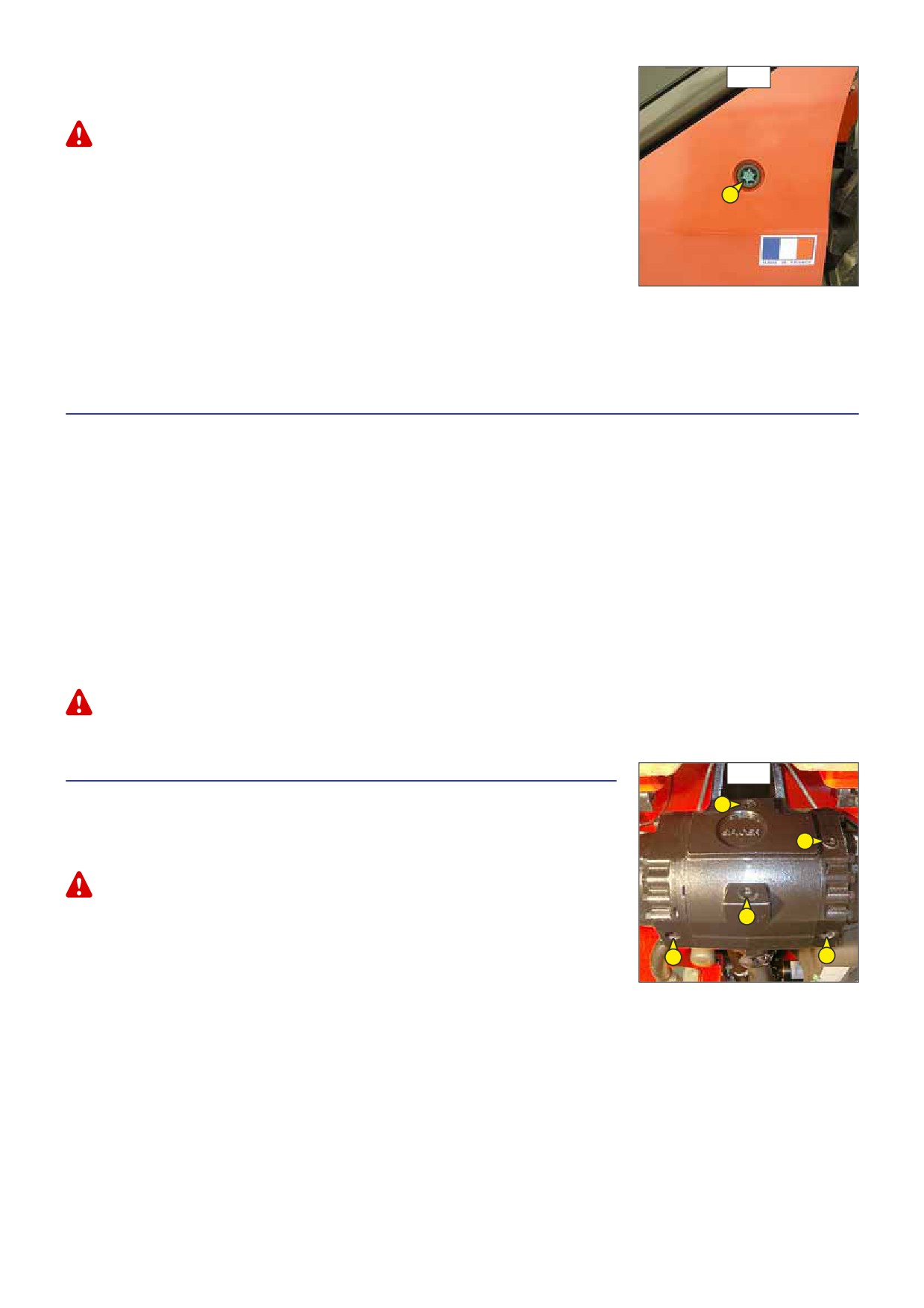
FILLING UP THE OIL
E6/4
- Clean and refit drain plugs 1 (fig. E6/1) (tightening torque 29 to 39 N.m).
- Fill up with oil (see: 3 - MAINTENANCE: LUBRICANTS AND FUEL) by filler port 4 (fig. E6/2).
Use a clean container and funnel and clean the underside of the oil drum before filling.
- Obser ve the oil level on dipstick 5 (fig. E6/4), the oil level should be at the level of the
red point.
5
- Check for any possible leaks at the drain plugs.
- Replace filler plug 2 (fig. E6/2) with a new filler plug (see: 3 - MAINTENANCE: FILTERS
CARTRIDGES AND BELTS).
HYDRAULIC CIRCUIT DECONTAMINATION
- Let the I.C. engine run (accelerator pedal at halfway travel) for 5 minutes without using
anything on the lift truck, then for 5 more minutes while using completely the hydraulic
movements (except the steering system and the ser vice brakes).
- Accelerate the I.C. engine at full speed for 1 minute, then activate the steering system.
- This operation makes a pollution abatement of the circuit possible through the hydraulic return oil filter.
E9 - SEAT BELT
CHECK
SEAT BELT WITH TWO ANCHORING POINTS
- Check the following points:
• Fixing of the anchoring points on the seat.
• Cleanness of the strap and the locking mechanism.
• Triggering of the locking mechanism.
• Condition of the strap (cuts, curled edges).
REELED BELT WITH TWO ANCHORING POINTS
- Check the points listed above together with the following points:
• The correct winding of the belt.
• Condition of the reel guards.
• Roller locking mechanism when the strap is given a sharp tug.
NOTE: After an accident, replace the seat belt.
In no event should the lift truck be used if the seat belt is defective (fixing, locking, cuts, tears, etc.). Repair or replace the seat belt immediately.
E10 - REAR AXLE DIFFERENTIAL OIL
E10
DRAIN
MT 728 Série D-E3
3
MT 928 Série D-E3
Place the lift truck on level ground with the I.C. engine stopped and the differential oil still
2
warm.
Dispose of the drain oil in an ecological manner.
- Place a container under drain plugs 1 (fig. E10) and unscrew them.
1
- Remove the level plug 2 (fig. E10) and the filler plug 3 (fig. E10) to ensure proper
emptying.
1
1
- Refit and tighten the drain plugs 1 (fig. E10) (tightening torque 34 to 49 N.m).
- Fill up with oil (see: 3 - MAINTENANCE: LUBRICANTS AND FUEL) by filler port 3 (fig. E10).
- The level is correct when the oil is level is flush with the edge of port 2 (fig. E10).
- Check for any possible leaks at the drain plugs.
- Refit and tighten the level plug 2 (fig. E10) (tightening torque 34 to 49 N.m) and the filler plug 3 (fig. E10) (tightening torque 34
to 49 N.m).
3-35

E11 - FRONT AND REAR WHEELS REDUCERS OIL
E11
DRAIN
Place the lift truck on level ground with the I.C. engine stopped and the reducers oil still
warm.
1
Dispose of the drain oil in an ecological manner.
B
- Drain and change each front wheel reducer.
- Place drain plug 1 (fig. E11) in position A.
A
- Place a container under the drain plug and unscrew the plug.
- Let the oil drain fully.
- Place the drain port in position B, i.e. in a level port.
- Fill up with oil (see: 3 - MAINTENANCE: LUBRICANTS AND FUEL) by level port 1 (fig. E11).
- The level is correct when the oil level is flush with the edge of the hole.
- Refit and tighten the drain plug 1 (fig. E11) (tightening torque 34 to 49 N.m).
- Repeat this operation on each rear wheel reducer.
3-36
3-37

F - EVERY 2000 HOURS SERVICE
Carry out the operations described previously as well as the following operations.
F1 - COOLING LIQUID
F1/1
DRAIN
MT 728 Série D-E3
MT 732 Série D-E3
MT 928 Série D-E3
MT 932 Série D-E3
MT 1030 S Série 4-E3
These operations are to be carried out if necessar y or ever y two years at the beginning of
winter. Place the lift truck on level ground with the I.C. engine stopped and cold.
1
DRAINING THE LIQUID
- Open the I.C. engine bonnet.
- Remove the shroud 1 (fig. F1/1).
- Set a container under drain valve 2 (fig. F1/2) on the radiator and drain plug 3 (fig. F1/3)
of the engine block and loosen them.
F1/2
- Remove filler cap 4 (fig. F1/4) of the radiator.
- Let the cooling circuit drain entirely while ensuring that the ports do not get clogged.
- Check the condition of the hoses as well as the fastening devices and change the hoses
if necessar y.
- Rinse the circuit with clean water and use a cleaning agent if necessar y.
2
FILLING THE LIQUID
- Tighten the drain valve 2 (fig. F1/2) and drain plug 3 (fig. F1/3) (tightening torque 40
N.m).
- Slowly fill up the circuit with cooling liquid (see: 3 - MAINTENANCE: LUBRICANTS AND
FUEL) to the middle of gauge 5 (fig. F1/4) through filler port 6 (fig. F1/4).
- Put back filler cap 4 (fig. F1/4).
- Run the I.C. engine at idle for a few minutes.
- Check for any possible leaks.
- Put back the shroud 1 (fig. F1/1)
F1/3
- Check the level and refill if necessar y.
The I.C. engine does not contain any corrosion resistor and must be filled during the whole year with a
mixture containing 25 % of ethylene glycol-based antifreeze.
3
F1/4
4
6
5
3-38

F1 - COOLING LIQUID
F1/1
DRAIN
MT 1030 S Turbo Série 4-E3
These operations are to be carried out if necessar y or ever y two years at the beginning of
winter. Place the lift truck on level ground with the I.C. engine stopped and cold.
DRAINING THE LIQUID
- Open engine hood and lift the batter y cover.
1
- Place a container under hose 1 (fig. F1/1) on the radiator and drain plug 2 (fig. F1/2) of
the engine block. Remove the hose and loosen the drain plug.
- Remove filling plug 3 (fig. F1/3) of the radiator.
- Let the cooling circuit drain entirely while ensuring that the ports do not get clogged.
- Check the condition of the hoses as well as the fastening devices and change the hoses
if necessar y.
- Rinse the circuit with clean water and use a cleaning agent if necessar y.
F1/2
FILLING THE LIQUID
- Refit and tighten the hose 1 (fig. F1/1) and drain plug 2 (fig. F1/2) (tightening torque
40 N.m).
- Slowly fill up the circuit with cooling liquid (see: 3 - MAINTENANCE: LUBRICANTS AND FUEL)
to the middle of gauge 4 (fig. F1/3) through filler port 5 (fig. F1/3).
- Put back filling plug 3 (fig. F1/3).
- Run the I.C. engine at idle for a few minutes.
2
- Check for any possible leaks.
- Check the level and refill if necessar y.
The I.C. engine does not contain any corrosion resistor and must be filled during the whole year with
a mixture containing 25 % of ethylene glycol-based antifreeze.
F1/3
3
5
4
F2 - AIR CONDITIONING (OPTION)
F2
CLEANING - INSPECTION
CLEANING CONDENSER AND EVAPORATOR COILS (*)
CLEANING CONDENSATE TRAY AND RELIEF VALVE (*)
COLLECTING COOLANT TO REPLACE FILTER-DRIER (*)
REFILLING WITH COOLANT AND CHECKING THE THERMOSTATIC CONTROL AND PRESSURE
SWITCHES (*)
NOTE: When opening the evaporator unit, remember to replace the cover seal.
(*): (CONSULT YOUR DEALER).
CAUTION: DO NOT ATTEMPT TO REPAIR ANY PROBLEMS YOURSELF. ALWAYS REFER TO YOUR DEALER
WHEN REFILLING CIRCUITS, AS THEY HOLD THE CORRECT SPARE PARTS, AS WELL AS HAVING THE
NECESSARY TECHNICAL KNOWLEDGE AND TOOLS.
- Do not open the circuit under any circumstances as this would cause the coolant to be lost.
- The cooling circuit contains a gas which can be dangerous under certain conditions. This gas, coolant R 134a, is colourless,
odourless and heavier than air.
• If this gas is inhaled, take the victim into fresh air, give oxygen or artificial respiration if necessary and call a doctor.
• If the gas is in contact with the skin, wash it immediately under running water and remove any contaminated garments.
• If the gas is in contact with the eyes, rinse them in clear water for 15 minutes and call a doctor.
- The compressor has an oil level gauge (fig. F2). Never unscrew this gauge because it would depressurizes the installation. The oil
level is only checked when changing the oil in the circuit.
3-39

G - OCCASIONAL MAINTENANCE
G1 - FUEL SYSTEM
G1/1
BLEED
These operations are to be carried out only in the following cases:
• A component of the fuel system replaced.
1
• A drained tank.
• Running out of fuel.
Ensure that the level of fuel in the tank is sufficient and bleed in the following order:
- Open the I.C. engine bonnet.
- Put the ignition on for three minutes on the lift truck, to give the lift pump time to release
air from the filter.
- Switch off the ignition with the ignition key.
G1/2
BLEEDING THE INJECTORS
- Remove the injectors cover 1 (fig. G1/1).
- Loosen high pressure connectors 2 (fig. G1/2) of all the injectors.
2
- Activate the starter until the diesel fuel flows out free of air at high pressure connectors
2
2 (fig. G1/2).
Do not engage the starter motor on a continual basis for more than 30 seconds and let it cool between
2
unsuccessful attempts.
2
- Tighten the connection while the diesel fuel is flowing out (tightening torque 30 N.m).
- The I.C. engine is then ready to be started up.
- Turn the I.C. engine over slowly for 5 minutes immediately after bleeding the fuel feed
circuit, in order to ensure that the injection pump has been bled thoroughly.
NOTE: If the I.C. engine functions correctly for a short time then stops or functions
irregularly, check for possible leaks in the low pressure circuit. If in doubt, contact your dealer.
G2 - WHEEL
G2/1
CHANGE
In the event of a wheel being changed on the public highway, make sure of the following points:
For this operation, we advise you to use the hydraulic jack MANITOU reference 505507 and
the safety support MANITOU reference 554772.
- Stop the lift truck, if possible on even and hard ground.
- To pass on stop of lift truck (see: 1 - OPERATING AND SAFETY INSTRUCTIONS: DRIVING
INSTRUCTIONS UNLADEN AND LADEN).
- Put the warning lights on.
- Immobilise the lift truck in both directions on the axle opposite to the wheel to be
changed.
- Unlock the nuts of the wheel to be changed.
- Place the jack under the flared axle tube, as near as possible to the wheel and adjust the
G2/2
jack (fig. G2/1).
- Lift the wheel until it comes off the ground and put in place the safety support under the
axle (fig. G2/2).
- Completely unscrew the wheel nuts and remove them.
- Free the wheel by reciprocating movements and roll it to the side.
- Slip the new wheel on the wheel hub.
- Refit the nuts by hand, if necessar y grease them.
- Remove the safety support and lower the lift truck with the jack.
- Tighten the wheel nuts with a torque wrench (see: 3 - MAINTENANCE: A - DAILY OR EVERY
10 HOURS SERVICE for tightening torque).
3-40

G3 - FRONT HEADLIGHTS
G3
ADJUST
h2 = h1 - (l x 2 / 100)
RECOMMENDED SETTING
(as per standard ECE-76/756 76/761 ECE20)
h1
Set to -2 % of the dipped beam in relation to the horizontal line of
+%
the headlamp.
-%
h1
ADJUSTING PROCEDURE
h2
- Place the lift truck unloaded and in the transport position and
perpendicular to a white wall on flat, level ground (fig. G3).
l
- Check the tyre pressures (see: 2 - DESCRIPTION: CHARACTERISTICS).
- Place the for ward/reverse selector in neutral and release the
parking brake.
CALCULATING THE HEIGHT OF THE DIPPED BEAM (H2)
• h1
= Height of the dipped beam in relation to the ground.
• h2
= Height of the adjusted beam.
• l
= Distance between the dipped beam and the white wall.
G4 - LIFT TRUCK
TOW
Do not tow the lift truck at more than 25 km/h.
- Place the for ward/reverse selector in neutral and the gear shift in neutral (according to model of lift truck).
- Release the parking brake.
- Put the warning lights on.
- If the I.C. engine is not running there will be no steering or braking assistance. Operate the steering and pedal slowly avoiding
sudden jerky movements.
G5 - LIFT TRUCK
G5/1
SLING
MT 728 Série D-E3
MT 928 Série D-E3
- Take into account the position of the lift truck centre of gravity for lifting
(fig. G5/1).
A =
mm
B =
mm
MT 728 Série D-E3
A =
mm
B =
mm
MT 928 Série D-E3
- Place the hooks in the fastening points provided (fig. G5/2 and G5/3).
A
B
G5/2
G5/3
3-41

MT 732 Série D-E3
G5/1
MT 932 Série D-E3
- Take into account the position of the lift truck centre of gravity for lifting
(fig. G5/1).
A = 1456 mm
B = 1104 mm
MT 732 Série D-E3
A = 1459 mm
B = 1101 mm
MT 932 Série D-E3
- Place the hooks in the fastening points provided (fig. G5/2 and G5/3).
A
B
G5/2
G5/3
MT 1030 S Série 4-E3
G5/1
MT 1030 S Turbo Série 4-E3
- Take into account the position of the lift truck centre of gravity for lifting
(fig. G5/1).
A = 1213 mm
B = 1477 mm
MT 1030 S Série 4-E3
A = 1208 mm
B = 1482 mm
MT 1030 S Turbo Série 4-E3
- Place the hooks in the fastening points provided (fig. G5/2 and G5/3).
A
B
G5/2
G5/3
3-42
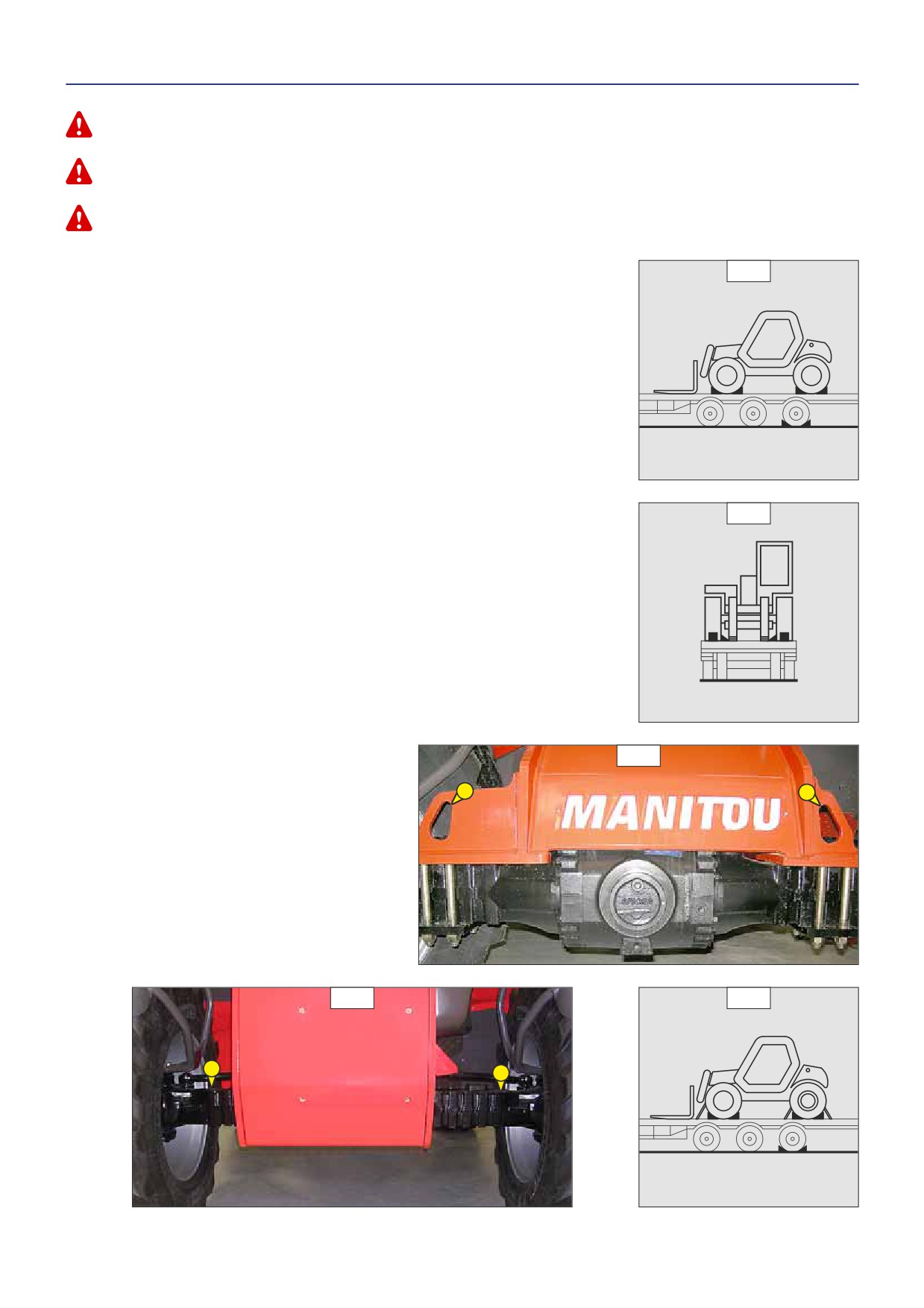
G6 - LIFT TRUCK ON A PLATFORM
TRANSPORT
Ensure that the safety instructions connected to the platform are respected before the loading of the lift truck and that the driver of the means of
transport is informed about the dimensions and the weight of the lift truck (see: 2 - DESCRIPTION: CHARACTERISTICS).
Ensure that the platform has got dimensions and a load capacity sufficient for transporting the lift truck. Check also the pressure on the contact surface
allowable for the platform in connection with the lift truck.
For lift trucks equipped with a turbo-charged I.C. engine, block off the exhaust outlet to avoid rotation of the turbo shaft without lubrication when
transporting the vehicle.
MT 728 Série D-E3
G6/1
MT 928 Série D-E3
LOAD THE LIFT TRUCK
- Block the wheels of the platform.
- Fix the loading ramps so that you obtain an angle as little as possible to lift the lift truck.
- Load the lift truck parallel to the platform.
- Stop the lift truck (see: 1 - OPERATING AND SAFETY INSTRUCTIONS: DRIVING INSTRUCTIONS
UNLADEN AND LADEN).
STOW THE LIFT TRUCK
- Fix the chocks to the platform at the front and at the back of each tyre (fig. G6/1).
- Fix also the chocks to the platform in the inside of each tyre (fig. G6/2).
- Stow the lift truck on the platform using sufficiently strong ropes. At the front of the lift
truck, on the fastening points 1 (fig. G6/3) and at the back, over the axle 2 (fig. G6/4).
- Tighten the ropes (fig. G6/5).
G6/2
G6/3
1
1
G6/4
G6/5
2
2
3-43

MT 732 Série D-E3
G6/1
MT 932 Série D-E3
MT 1030 S Série 4-E3
MT 1030 S Turbo Série 4-E3
LOAD THE LIFT TRUCK
- Block the wheels of the platform.
- Fix the loading ramps so that you obtain an angle as little as possible to lift the lift truck.
- Load the lift truck parallel to the platform.
- Stop the lift truck (see: 1 - OPERATING AND SAFETY INSTRUCTIONS: DRIVING INSTRUCTIONS
UNLADEN AND LADEN).
STOW THE LIFT TRUCK
- Fix the chocks to the platform at the front and at the back of each tyre (fig. G6/1).
- Fix also the chocks to the platform in the inside of each tyre (fig. G6/2).
- Secure the lift truck to the platform with sufficiently strong ropes. At the front of the lift
G6/2
truck, attach the ropes to the fastening points 1 (fig. G6/3) and at the rear to the towing
pin 2 (fig. G6/4).
- Tighten the ropes (fig. G6/5).
G6/3
1
1
MT 732 ... / MT 932 ...
G6/3
1
1
MT 1030 S ...
G6/4
G6/4
G6/5
2
2
MT 732 ... / MT 932 ...
MT 1030 S ...
3-44
4 - OPTIONAL
ATTACHMENTS
FOR USE WITH
THE RANGE
4-1
4-2
TABLE OF CONTENTS
INTRODUCTION
4-5
PICKING UP THE ATTACHMENTS
4-6
TECHNICAL SPECIFICATIONS OF ATTACHMENTS
4-10
ATTACHMENT SHIELDS
4-18
4-3
4-4
INTRODUCTION
-
Your lift truck must be used with interchangeable equipment. These items are called: ATTACHMENTS.
-
A wide range of attachments, specially designed and per fectly suitable for your lift truck is available and guaranteed by
MANITOU.
-
The attachments are delivered with a load chart concerning your lift truck. The operator’s manual and the load chart should be
kept in the places provided in the lift truck. For standard attachments, their use is governed by the instructions contained on this
notice.
We would remind users that the MT 928 Série D-E3, MT 932 Série D-E3, MT 1030 S Série 4-E3, MT 1030 S Turbo Série 4-E3, are lift trucks essentially
intended for handling. Occasional use with the buckets CBC 800/900 and CBR 900/1000 is authorised, but under no circumstances is intensive use
for difficult applications (quarry, waste, cereals, agriculture, etc) permissible.
In addition, use of the lift truck with the buckets CBC 800/900 and CBR 900/1000 should be with the jib completely retracted, in order to reduce the
constraints on the jib head.
Use other buckets CBA, CBC, CBM, CBR, CB, CBG and manure forks FFGR is forbidden.
-
Some particular uses require the adaptation of the attachment which is not provided in the price-listed options. Optional solutions
exist, consult your dealer.
All attachments with a suspended load (winch, crane jib, crane jib with winch, hook, etc.) MUST be used with a lift truck equipped with a hydraulic
movement cut-out device. In this case, the movement cut-out must be switched on and the transverse attitude perfectly horizontal.
Only attachments approved by MANITOU are to be used on our lift trucks (see: 4 - ADAPTABLE ATTACHMENTS IN OPTION ON THE RANGE: TECHNICAL
SPECIFICATIONS OF ATTACHMENTS). The manufacturer’s liability will be denied in case of modification or of attachment adaptation carried out without
his knowing it.
The single side-shift carriage (TSDL) is only compatible with the following attachments:
• floating fork carriage (TFF)
• tilting fork carriage (PFB)
• loading bucket (CBR)
• concrete bucket (BB, BBG)
• spout bucket (GL)
• crane jib and crane jib with winch (P, PT, PO, PC)
• winch (H)
• fixed platform, swivelling platform, roofer’s platform.
It is prohibited to use any other attachments on the TSDL.
Attachments authorised for use on the TSDL must comply strictly with the applications for which they are designed.
It is prohibited to use them for any other application (for example, earth moving, excavation, desurfacing, back scraping, etc. for the loading bucket
CBR) or any application placing abnormal stress on the structure of the TSDL: risk of deformation which could cause the load to fall.
Depending on their size, certain attachments may, when the jib is lowered and retracted, come into contact with the front tyres and cause damage
to them, if reverse tilt is activated in the forward tilt direction. TO REMOVE THIS RISK, EXTEND THE TELESCOPE TO A SUFFICIENT EXTENT FOR THE
PARTICULAR LIFT TRUCK AND ATTACHMENT SO THAT THIS CONTACT IS NOT POSSIBLE.
Maximum loads are defined by the capacity of a lift truck taking account of the attachment’s mass and centre of gravity. In the event of the attachment
having less capacity than the lift truck, never exceed this limit.
4-5

PICKING UP THE ATTACHMENTS
A - ATTACHMENT WITHOUT HYDRAULICS ANDHANDLOCKINGDEVICE
A
TAKING UP AN ATTACHMENT
- Ensure that the attachment is in a position facilitating the locking to the carriage. If it is
not correctly oriented, take the necessar y precautions in order to move it safely.
- Check that the locking pin and the clip are in position in the bracket (fig. A).
- Place the lift truck with the jib fully lowered in front of and parallel to the attachment, tilt
the carriage for wards (fig. B).
- Bring the carriage under the locking tube of the attachment, slightly lift the jib, incline the
carriage backwards in order to position the attachment (fig. C).
- Lift the attachment off the ground to facilitate locking.
HAND LOCKING
- Take the locking pin and the clip on the bracket (fig. A) and lock the attachment (fig. D).
Do not forget to refit the clip.
B
HAND RELEASING
- Proceed in the reverse order of paragraph HAND LOCKING while making sure you put back
the locking pin and the clip in the bracket (fig. A).
LAYING AN ATTACHMENT
- Proceed in the reverse order of paragraph TAKING UP AN ATTACHMENT while making sure
you place the attachment flat on the ground and in closed position.
C
D
4-6
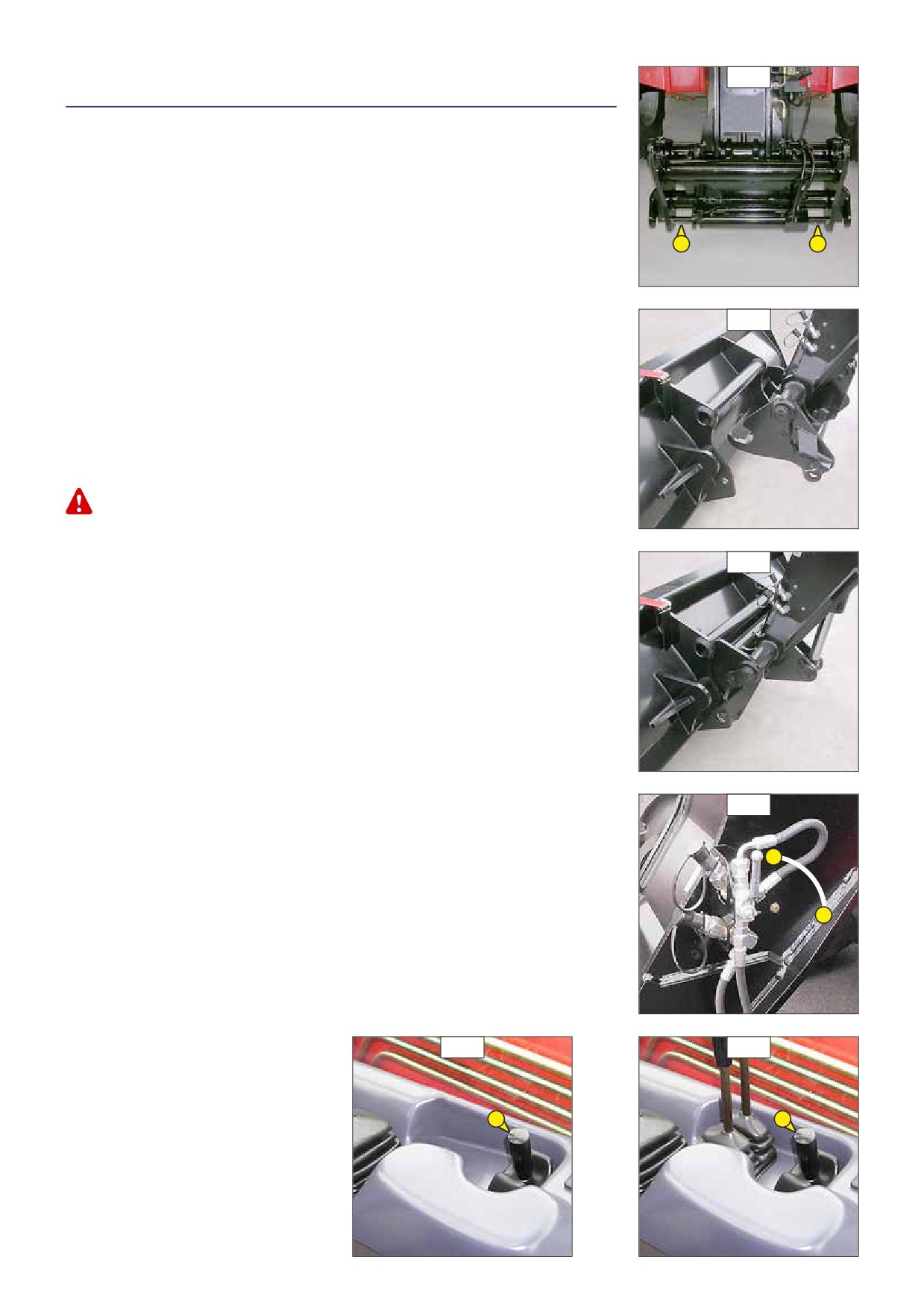
B- ATTACHMENT WITHOUT HYDRAULICS AND HYDRAULIC LOCKING DEVICE
A
(OPTION)
MT 732 Série D-E3
MT 932 Série D-E3
MT 1030 S Série 4-E3
MT 1030 S Turbo Série 4-E3
TAKING UP AN ATTACHMENT
- Ensure that the attachment is in a position facilitating the locking to the carriage. If it is
not correctly oriented, take the necessar y precautions in order to move it safely.
- Check that the rods on the locking cylinder are retracted (fig. A).
- Place the lift truck with the jib lowered in front of and parallel to the attachment, tilt the
carriage for wards (fig. B).
- Bring the carriage under the locking tube of the attachment, slightly lift the jib, incline the
carriage backwards in order to position the attachment (fig. C).
B
- Lift the attachment off the ground to facilitate locking.
HYDRAULIC LOCKING
- Put the valve in position A (fig. D), that is to say, the hydraulic circuit of the attachment
locking open.
- Lift up and push the lever of the distributor 1 (fig. E) to the right in order to completely lock
the attachment on the carriage.
- Close the valve in position B (fig. D), that is to say, the hydraulic circuit of the attachment
locking closed.
Always close the valve in position B (fig. D) after the locking of the attachment, in order to avoid
accidental unlocking and use the attachment safety.
HYDRAULIC RELEASING
- Put the valve in position A (fig. D), that is to say, the hydraulic circuit of the attachment
C
locking open.
- Lift up and push the lever of the distributor 1 (fig. E) to the left in order to unlock the
attachment.
LAYING AN ATTACHMENT
- Proceed in the reverse order of paragraph TAKING UP AN ATTACHMENT while making sure
you place the attachment flat on the ground and in closed position.
D
A
B
E
E
1
1
MT 732 ... / MT 932 ...
MT 1030 ...
4-7

C- HYDRAULICATTACHMENT ANDHANDLOCKINGDEVICE
A
STANDARD MT 732 Série D-E3
MT 932 Série D-E3
MT 1030 S Série 3-E3
MT 1030 S Turbo Série 3-E3
OPTION MT 728 Série D-E3
MT 928 Série D-E3
TAKING UP AN ATTACHMENT
- Ensure that the attachment is in a position facilitating the locking to the carriage. If it is
not correctly oriented, take the necessar y precautions in order to move it safely.
- Check that the locking pin and the clip are in position in the bracket (fig. A).
- Place the lift truck with the jib lowered in front of and parallel to the attachment, tilt the
carriage for wards (fig. B).
- Bring the carriage under the locking tube of the attachment, slightly lift the jib, incline the
B
carriage backwards in order to position the attachment (fig. C).
- Lift the attachment off the ground to facilitate locking.
HAND LOCKING AND CONNECTING THE ATTACHMENT
- Take the locking pin and the clip on the bracket (fig. A) and lock the attachment (fig. D).
Do not forget to refit the clip.
- Stop the I.C. engine.
- Remove the pressure of the hydraulic circuit by using the lever of the distributor 1 (fig.
E).
- Connect the rapid connectors according to the logic of the attachment’s hydraulic
movements.
Make sure that the rapid connectors are clean and protect the holes which are not used, with the caps
provided.
C
HAND RELEASING AND DISCONNECTING THE ATTACHMENT
- Proceed in the reverse order of paragraph HAND LOCKING AND CONNECTING THE
ATTACHMENT while making sure you put back the locking pin and the clip in the bracket
(fig. A).
LAYING AN ATTACHMENT
- Proceed in the reverse order of paragraph TAKING UP AN ATTACHMENT while making sure
you place the attachment flat on the ground and in closed position.
D
E
E
E
1
1
1
MT 728 ... / MT 928 ...
MT 732 ... / MT 932 ...
MT 1030 ...
4-8

D- HYDRAULICATTACHMENT ANDHYDRAULICLOCKINGDEVICE (OPTION)
A
MT 732 Série D-E3
MT 932 Série D-E3
MT 1030 S Série 4-E3
MT 1030 S Turbo Série 4-E3
TAKING UP AN ATTACHMENT
- Ensure that the attachment is in a position facilitating the locking to the carriage. If it is
not correctly oriented, take the necessar y precautions in order to move it safely.
- Check that the rods on the locking cylinder are retracted (fig. A).
- Place the lift truck with the jib lowered in front of and parallel to the attachment, tilt the
carriage for wards (fig. B).
- Bring the carriage under the locking tube of the attachment, slightly lift the jib, incline the
carriage backwards in order to position the attachment (fig. C).
- Lift the attachment off the ground to facilitate locking.
B
HYDRAULIC LOCKING AND CONNECTING THE ATTACHMENT
- Put the valve in position A (fig. D), that is to say, the hydraulic circuit of the attachment
locking open.
- Lift up and push the lever of the distributor 1 (fig. E) to the right in order to completely lock
the attachment on the carriage.
- Stop the I.C. engine.
- Remove the pressure of the attachment hydraulic circuit by using the lever of the distributor
1 (fig. E).
- Connect the rapid connectors according to the logic of the attachment’s hydraulic
movements.
Make sure that the rapid connectors are clean and protect the holes which are not used, with the caps
provided.
- Close the valve in position B (fig. D), that is to say, the hydraulic circuit of the attachment
C
locking closed.
Always close the valve in position B (fig. D) after the locking of the attachment, in order to avoid
accidental unlocking and use the attachment safety.
HYDRAULIC RELEASING AND DISCONNECTING THE ATTACHMENT
- Close the attachment.
- Put the valve in position A (fig. D), that is to say, the hydraulic circuit of the attachment
locking open.
- Lift up and push the lever of the distributor 1 (fig. E) to the left in order to unlock the
attachment.
- Stop the I.C. engine.
- Remove the pressure of the attachment hydraulic circuit by using the lever of the distributor
1 (fig. E).
- Disconnect the rapid connectors of the attachment.
D
Make sure that the rapid connectors are clean and protect the holes which are not used, with the caps
provided.
A
LAYING AN ATTACHMENT
- Proceed in the reverse order of paragraph TAKING UP AN ATTACHMENT while making sure
B
you place the attachment flat on the ground and in closed position.
E
E
1
1
MT 732 ... / MT 932 ...
MT 1030 ...
4-9

TECHNICAL SPECIFICATIONS OF ATTACHMENTS
FLOATING FORK CARRIAGE
TFF 35 MT-1040
TFF 35 MT-1300
PART NUMBER
654093
654094
Rated capacity
3500 kg
3500 kg
Width
1040 mm
1300 mm
Weight
300 kg
340 kg
FLOATING FORK SIDE-SHIFT CARRIAGE
Use is prohibited with the optional single side-shift carriage (TSDL).
TFF 35 MT-1040 DL
TFF 35 MT-1300 DL
PART NUMBER
751543
751544
Rated capacity
3500 kg
3500 kg
Side-shift
2x100 mm
2x100 mm
Width
1040 mm
1300 mm
Weight
345 kg
375 kg
FLOATING FORK
PART NUMBER
415801
Section
125x45x1200 mm
Weight
68 kg
4-10

STANDARDISED TILTING FORK CARRIAGE
PFB 35 N MT-1260 S2
PFB 35 N MT-1470 S2
PFB 35 N MT-1580 S2
PART NUMBER
653744
653745
653746
Rated capacity
3500 kg
3500 kg
3500 kg
Width
1260 mm
1470 mm
1580 mm
Weight
103 kg
126 kg
131 kg
STANDARDISED SIDE-SHIFT CARRIAGE
Use is prohibited with the optional single side-shift carriage (TSDL).
TDL 3T5 L1260 FEM3
TDL 5T L1470 FEM3
TDL 5T L1580 FEM3
PART NUMBER
751375
751376
751377
Rated capacity
3000 kg
5000 kg
5000 kg
Side-shift
2x100 mm
2x100 mm
2x100 mm
Width
1260 mm
1470 mm
1580 mm
Weight
79 kg
192 kg
200 kg
STANDARDISED FORK
PART NUMBER
415618
Section
125x45x1200 mm
Weight
72 kg
LOAD BACK REST
PART NUMBER
556008
555325
556010
Width
1260 mm
1470 mm
1580 mm
Weight
36 kg
39 kg
41 kg
4-11

BUILDING BUCKET
MT 728 Série D-E3
MT 732 Série D-E3
CBC 700 L1950 S2
PART NUMBER
654472
Rated capacity
697 l
Width
1950 mm
Weight
330 kg
BUILDING BUCKET
Use is prohibited with the optional single side-shift carriage (TSDL).
CBC 800 L2250 S3
CBC 900 L2450 S3
PART NUMBER
654471
654470
Rated capacity
814 l
893 l
Width
2250 mm
2450 mm
Weight
385 kg
410 kg
LOADING BUCKET
MT 728 Série D-E3
MT 732 Série D-E3
CBR 780 L1950 S2
PART NUMBER
570613
Rated capacity
778 l
Width
1950 mm
Weight
340 kg
LOADING BUCKET
Use is prohibited with the optional single side-shift carriage (TSDL).
CBR 900 L2250 S2
CBR 1000 L2450 S2
PART NUMBER
653749
654716
Rated capacity
904 l
990 l
Width
2250 mm
2450 mm
Weight
390 kg
410 kg
4-12
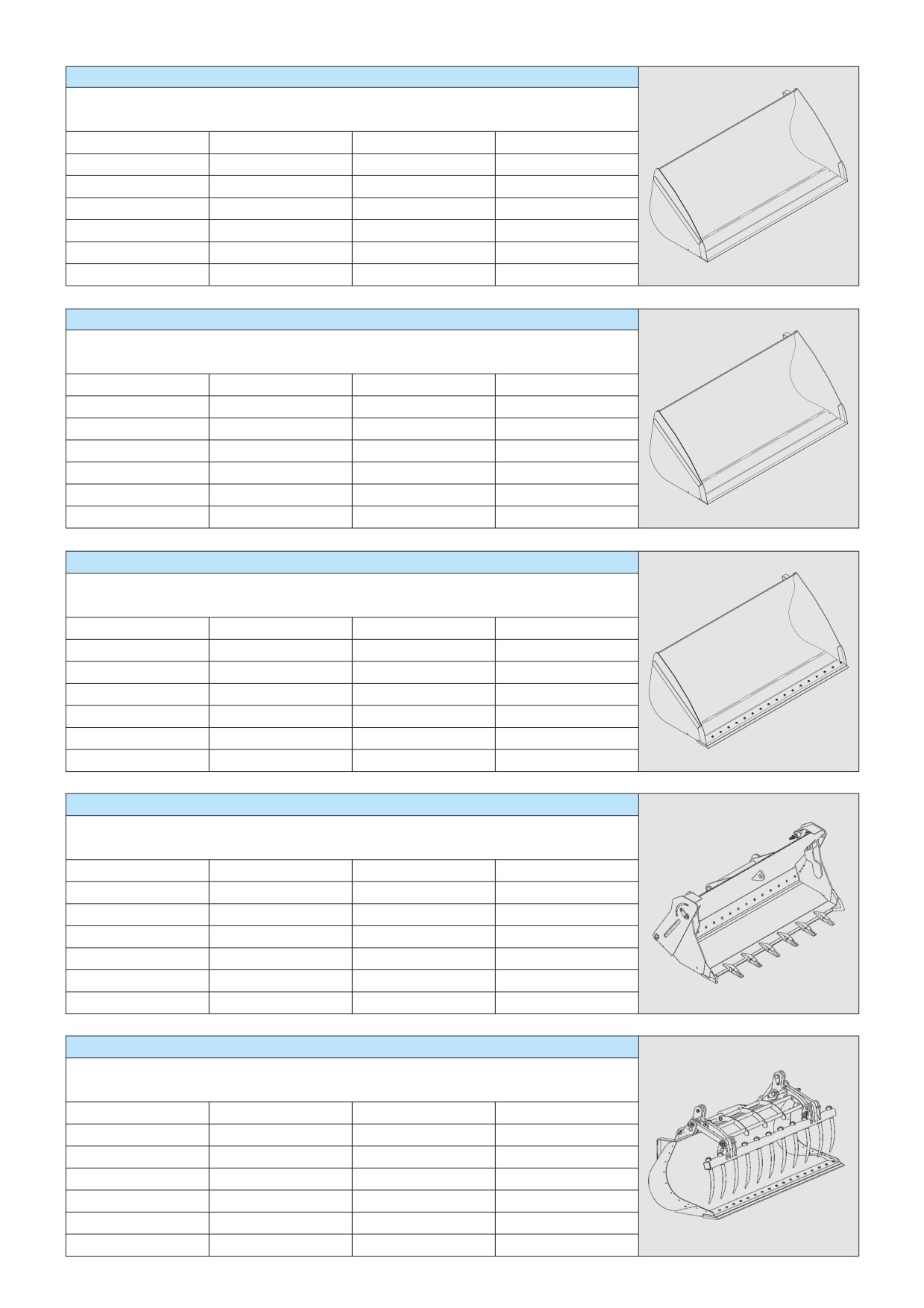
GRAIN BUCKET
MT 728 Série D-E3
MT 732 Série D-E3
CBA 1500 L2450 S3
CBA 1800 L2250 S3
PART NUMBER
570547
570550
Rated capacity
1502 l
1820 l
Width
2450 mm
2250 mm
Weight
514 kg
571 kg
GRAIN BUCKET
MT 728 Série D-E3
MT 732 Série D-E3
CBA 2000 L2450 S3
CBA 2500 L2450 S3
PART NUMBER
570551
570553
Rated capacity
1998 l
2508 l
Width
2450 mm
2450 mm
Weight
607 kg
701 kg
GRAIN BUCKET (REVERSING AND DISMOUNTABLE CUTTING EDGE)
MT 728 Série D-E3
MT 732 Série D-E3
CBA 1500 L2450 LDR S3
CBA 2000 L2450 LDR S3
CBA 2500 L2450 LDR S3
PART NUMBER
570548
570552
570554
Rated capacity
1502 l
1998 l
2508 l
Width
2450 mm
2450 mm
2450 mm
Weight
585 kg
678 kg
772 kg
BUCKET 4X1
MT 728 Série D-E3
MT 732 Série D-E3
CB4x1-700 L1950
CB4x1-850 L2300
CB4x1-900 L2450
PART NUMBER
751402
751401
751465
Rated capacity
700 l
850 l
900 l
Width
1950 mm
2300 mm
2450 mm
Weight
640 kg
735 kg
765 kg
MULTIPURPOSE BUCKET (REVERSING AND DISMOUNTABLE CUTTING EDGE)
MT 728 Série D-E3
MT 732 Série D-E3
CBM 2450 LDR S5
PART NUMBER
752195
Rated capacity
1,03 m3
Width
2450 mm
Grab
11
Weight
790 kg
4-13

GRAB BUCKET
MT 728 Série D-E3
MT 732 Série D-E3
CBG 1950 S4
CBG 2300 S4
CBG 2450 S4
PART NUMBER
751407
751414
751418
Rated capacity
1 m3
1,2 m3
1,26 m3
Width
1950 mm
2300 mm
2450 mm
Grab
7
8
8
Weight
555 kg
615 kg
635 kg
GRAB BUCKET (NON-HAZARDOUS INDUSTRIAL WASTE)
MT 728 Série D-E3
MT 732 Série D-E3
CBG 1950 DIB S4
CBG 2300 DIB S4
CBG 2450 DIB S4
PART NUMBER
653016
653018
653020
Rated capacity
1 m3
1,2 m3
1,26 m3
Width
1950 mm
2300 mm
2450 mm
Grab
7
8
8
Weight
678 kg
740 kg
767 kg
GRAB BUCKET (GRAB CLOSED)
MT 728 Série D-E3
MT 732 Série D-E3
CBG 2300 GF S4
PART NUMBER
653008
Rated capacity
1,2 m3
Width
2300 mm
Grab
8
Weight
637 kg
GRAB BUCKET (CLOSED JAWS AND REVERSIBLE REMOVABLE BLADE)
MT 728 Série D-E3
MT 732 Série D-E3
CBG 1950 JFD-LDR S4
CBG 2300 JFD-LDR S4
CBG 2450 JFD-LDR S4
PART NUMBER
653003
653006
653009
Rated capacity
1 m3
1,2 m3
1,26 m3
Width
1950 mm
2300 mm
2450 mm
Grab
7
8
8
Weight
655 kg
715 kg
742 kg
4-14

CONCRETE BUCKET (ADAPTABLE ON FORKS)
BB 500 S4
BBH 500 S4
PART NUMBER
654409
751462
Rated capacity
500 l/1300 kg
500 l/1300 kg
Width
1100 mm
1100 mm
Weight
205 kg
220 kg
CONCRETE BUCKET WITH SPOUT (ADAPTABLE ON FORKS)
BBG 500 S4
BBHG 500 S4
PART NUMBER
654411
751464
Rated capacity
500 l/1300 kg
500 l/1300 kg
Width
1100 mm
1100 mm
Weight
220 kg
235 kg
SPOUT BUCKET (ADAPTABLE ON FORKS)
GL 300 S2
GL 400 S2
PART NUMBER
174371
174372
Rated capacity
300 l/725 kg
400 l/969 kg
Weight
150 kg
166 kg
HYDRAULIC KIT TO OPEN THE SPOUT
PART NUMBER
653750
SPOUT BUCKET (ADAPTABLE ON FORKS)
GL 600 S2
GL 800 S2
PART NUMBER
174373
174374
Rated capacity
600 l/1440 kg
800 l/1920 kg
Weight
290 kg
325 kg
HYDRAULIC KIT TO OPEN THE SPOUT
PART NUMBER
653750
SPOUT BUCKET (ADAPTABLE ON FORKS)
GL 1000 S2
GL 1500 S2
PART NUMBER
174375
174376
Rated capacity
1000 l/2440 kg
1500 l/3591 kg
Weight
360 kg
409 kg
HYDRAULIC KIT TO OPEN THE SPOUT
PART NUMBER
653750
4-15

MANURE FORK WITH GRAB
MT 728 Série D-E3
MT 732 Série D-E3
FFGR 30 MT 2100 S5
FFGR 30 MT 2400 S5
FFGR 30 MT 2100 DR
PART NUMBER
556843
570594
570728
Rated capacity
1700 Kg
1700 Kg
1700 Kg
Width
2100 mm
2400 mm
2100 mm
Finger
10
12
10 (round finger)
Grab
7
8
7
Weight
567 kg
606 kg
567 kg
WINCH
MUST be used with a lift truck equipped with an operational hydraulic movement cut-out device.
MT 1030 S Série 4-E3
MT 1030 S Turbo Série 4-E3
H3T S4
H4T S4
PART NUMBER
708534
708535
Rated capacity
3000 Kg
4000 Kg
Weight
310 kg
420 kg
4-16

CRANE JIB
MUST be used with a lift truck equipped with an operational hydraulic movement cut-out device.
P 600 MT S3
PART NUMBER
653228
Rated capacity
600 kg
Weight
170 kg
CRANE JIB
MUST be used with a lift truck equipped with an operational hydraulic movement cut-out device.
P 4000 MT S2
PART NUMBER
653226
Rated capacity
4000 kg/1200 kg
Weight
210 kg
CRANE JIB WITH WINCH
MUST be used with a lift truck equipped with an operational hydraulic movement cut-out device.
PT 600 MT S6
PART NUMBER
708538
Rated capacity
600 kg
Weight
288 kg
15°/15° MULTI-DIRECTIONAL CRANE JIB
MUST be used with a lift truck equipped with an operational hydraulic movement cut-out device.
PO 600 L2500 S2
PO 1000 L1500 S2
PO 2000 L1000 S2
PART NUMBER
751547
751548
751549
Rated capacity
600 kg
1000 kg
2000 kg
Weight
320 kg
275 kg
255 kg
CRANE JIB
MUST be used with a lift truck equipped with an operational hydraulic movement cut-out device.
PC 50
PART NUMBER
708544
Rated capacity
5000 kg
Weight
120 kg
4-17
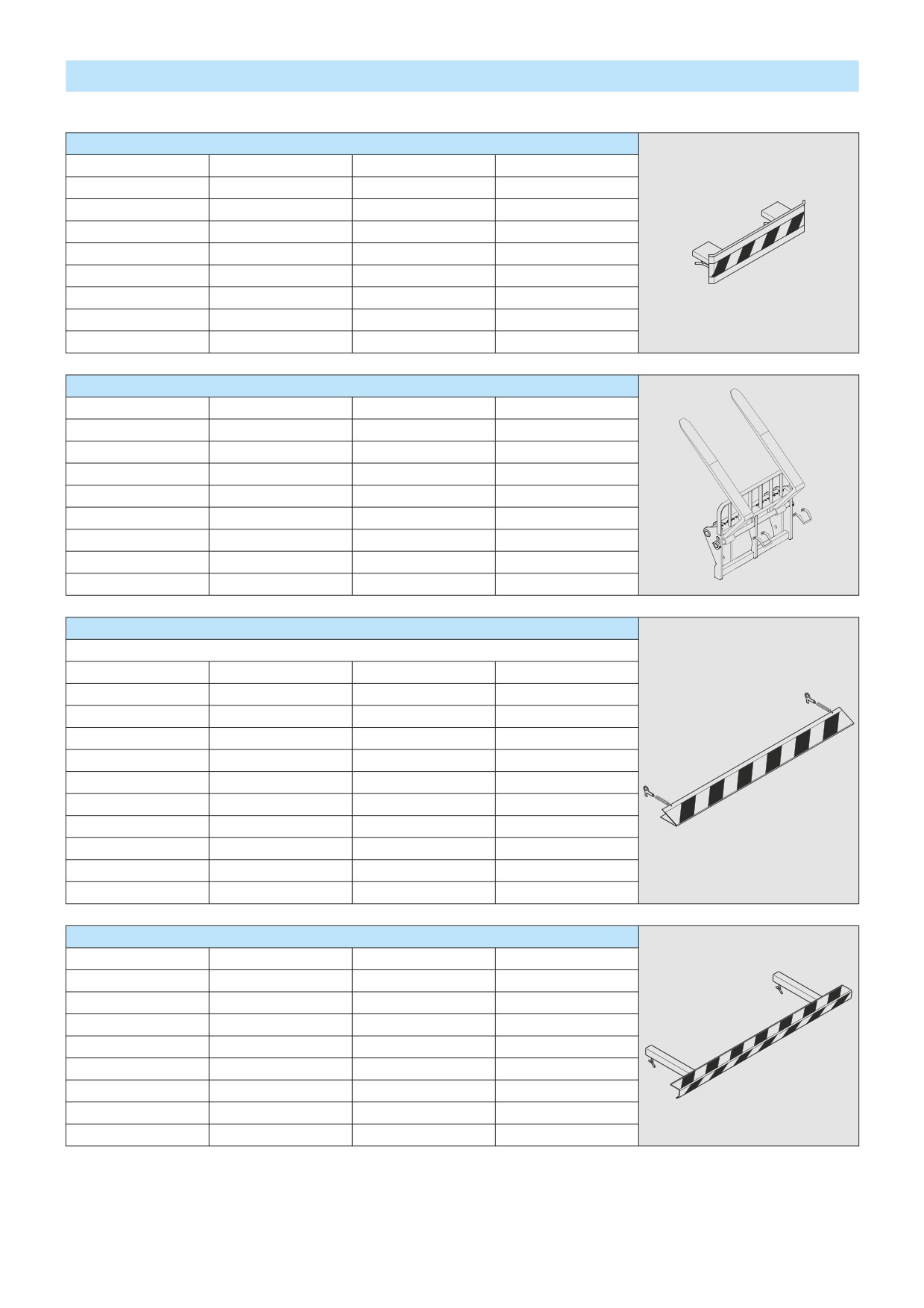
ATTACHMENT SHIELDS
FORK PROTECTOR
PART NUMBER
227801
FORK BLOCK FOR FLOATING FORK CARRIAGE
PART NUMBER
261210
BUCKET PROTECTOR
NOTE: Always ensure that the width of the protector you choose is less than or equal to the width of the bucket.
PART NUMBER
206734
206732
206730
Width
1375 mm
1500 mm
1650 mm
PART NUMBER
235854
206728
206726
Width
1850 mm
1950 mm
2000 mm
PART NUMBER
223771
223773
206724
Width
2050 mm
2100 mm
2150 mm
PART NUMBER
206099
206722
223775
Width
2250 mm
2450 mm
2500 mm
MANURE FORK PROTECTOR
PART NUMBER
230689
4-18
5 - SPECIFIC AUSTRALIA
See also the operator’s manual supplement: 647065 AU
5-1

LOAD CHART
MT 732 Série D-E3
MT732
8
50°
60°
63°
6.90m
E
40°
D
36km/h Maxi
6
C
(10m/s)
Ground conditions:
B
solid surface
5
A
10% maxi
30°
4
kg
36km/h Maxi
10% maxi
20°
3
(10m/s)
kg
2
12km/h Maxi (3,33m/s)
10°
5% maxi
1
0°
kg
Ground conditions:
0
solid surface
P
-3°
0.6m
15% maxi
10% maxi
5
4
3
2
1
0
0km/h
kg
5% maxi
5% maxi
Standard used AS 1418-19
Standard used AS 1418-19
Standard used AS 1418-19
MT 932 Série D-E3
MT932
50°
60° 61.5°
10
40°
9m
9
E
D
36km/h Maxi
8
(10m/s)
Ground conditions:
C
7
solid surface
10% maxi
30°
B
6
A
5
kg
36km/h Maxi
20°
4
(10m/s)
10% maxi
3
kg
10°
12km/h Maxi (3,33m/s)
2
5% maxi
1
0°
kg
Ground conditions:
0m
solid surface
0.6m
15% maxi
10% maxi
-5°
P
-1
7
6
5
4
3
2
1
0
0km/h
kg
5% maxi
5% maxi
Standard used AS 1418-19
Standard used AS 1418-19
Standard used AS 1418-19
5-3

LOAD CHART
MT 1030 S Turbo Série 4-E3
MT1030S
50°
60° 61°
10
E
40°
9
D
8
C
10% maxi
7
30°
B
6
A
kg
5
36km/h Maxi
(10m/s)
10% maxi
20°
4
kg
3
10°
2
5% maxi
1
Ground conditions:
0°
solid surface
P
0m
-5°
D
C
B
A
0.6m
E
-1
0km/h
7
6
5
4
3
2
1
0m
Standard used AS 1418-19
Standard used AS 1418-19
MT1030S
50°
60°
67°
10
E
9.98
40°
9
D
10% maxi
8
C
7
B
30°
36km/h Maxi
kg
6
A
(10m/s)
10% maxi
5
20°
4
kg
3
5% maxi
10°
2
Ground conditions:
solid surface
1
P
0°
0m
E
D
C
B
A
-0.5
0km/h
7
6
5
4
3
2
1
0m
0.6m
Standard used AS 1418-19
Standard used AS 1418-19
36km/h Maxi
(10m/s)
Ground conditions:
solid surface
12km/h Maxi (3,33m/s)
kg
15% maxi
10% maxi
kg
5% maxi
5% maxi
Standard used AS 1418-19
5-4