MANITOU MT 728, MT 732, MT 928, MT 932, MT 1030 S, MT 1030 S Turbo. Operator's Manual - part 1

MANITOU BF
BP 10249
44158 ANCENIS CEDEX - FRANCE
TEL: + 33 (0)2 40 09 10 11
YOUR DEALER
547998 EN (19/03/2010)
MT 728 Série D-E3
MT 732 Série D-E3
MT 928 Série D-E3
MT 932 Série D-E3
MT 1030 S Série 4-E3
MT 1030 S Turbo Série 4-E3
OPERATOR’S MANUAL
THIS OPERATOR’S MANUAL MUST BE KEPT IN THE LIFT TRUCK AND MUST BE READ AND UNDERSTOOD BY OPERATORS.

1 - OPERATING AND SAFETY INSTRUCTIONS
2 - DESCRIPTION
3 - MAINTENANCE
4 - ADAPTABLE ATTACHMENTS IN OPTION ON THE RANGE
5 - SPECIFIC AUSTRALIA
See also the operator’s manual supplement: 647065 AU
07/03/2008
1ST DATE OF ISSUE
19/03/2010
UP DATING (1-3 - 1-6 ; 1-10 ; 1-12 - 1-14 ; 1-21 - 1-23 ; 2-3 - 2-32 ; 2-42 ; 2-47 ; 2-53 ; 2-54 ; 2-58 ;
2-59 ; 2-66 ; 2-67 ; 2-68 ; 3-3 - 3-6 ; 3-9 ; 3-10 ; 3-11 ; 3-27 - 3-30 ; 3-40 - 3-44 ; 4-3 ;
4-18)
ADDING: 5 - SPECIFIC AUSTRALIA
THE TEXTS AND ILLUSTRATIONS IN THIS DOCUMENT MUST NOT BE REPRODUCED EITHER WHOLLY OR IN PART.

1 - OPERATING
AND SAFETY
INSTRUCTIONS
1-1
TABLE OF CONTENTS
INSTRUCTIONS TO THE COMPANY MANAGER
1-4
THE SITE
1 - 4
THE OPERATOR
1 - 4
THE LIFT TRUCK
1 - 4
A - THE LIFT TRUCK’S SUITABILITY FOR THE JOB
1 - 4
B - ADAPTATION OF THE LIFT TRUCK TO STANDARD ENVIRONMENTAL CONDITIONS
1 - 4
C - MODIFICATION OF THE LIFT TRUCK
1 - 5
D - FRENCH ROAD TRAFFIC RULES (or see current legislation in other countries)
1 - 5
THE INSTRUCTIONS
1 - 5
THE MAINTENANCE
1 - 5
INSTRUCTIONS FOR THE OPERATOR
1-6
PREAMBULE
1 - 6
GENERAL INSTRUCTIONS
1 - 6
A - OPERATOR’S MANUAL
1 - 6
B - AUTHORIZATION FOR USE IN FRANCE (or see current legislation in other countries)
1 - 6
C - MAINTENANCE
1 - 6
D - MODIFICATION OF THE LIFT TRUCK
1 - 6
E - LIFTING PEOPLE
1 - 7
OPERATING INSTRUCTIONS UNLADEN AND LADEN
1 - 8
A - BEFORE STARTING THE LIFT TRUCK
1 - 8
B - DRIVER’S OPERATING INSTRUCTIONS
1 - 8
C - ENVIRONMENT
1 - 9
D - VISIBILITY
1 - 9
E - STARTING THE LIFT TRUCK
1 - 10
F - DRIVING THE LIFT TRUCK
1 - 10
G - STOPPING THE LIFT TRUCK
1 - 11
H - DRIVING THE LIFT TRUCK ON THE PUBLIC HIGHWAY (or see current legislation in other countries)
1 - 12
INSTRUCTIONS FOR HANDLING A LOAD
1 - 14
A - CHOICE OF ATTACHMENTS
1 - 14
B - MASS OF LOAD AND CENTRE OF GRAVITY
1 - 14
C - LONGITUDINAL STABILITY ALARM
1 - 14
D - TRANSVERSE ATTITUDE OF THE LIFT TRUCK
1 - 15
E - TAKING UP A LOAD ON THE GROUND
1 - 15
F - TAKING UP AND LAYING A HIGH LOAD ON TYRES
1 - 16
G - TAKING UP AND LAYING A HIGH LOAD ON STABILIZERS
1 - 18
H - TAKING UP AND LAYING DOWN A SUSPENDED LOAD
1 - 20
I - TRAVELLING WITH A SUSPENDED LOAD
1 - 20
PLATFORM OPERATING INSTRUCTIONS
1 - 21
A - AUTHORISATION FOR USE
1 - 21
B - SUITABILITY OF THE PLATFORM FOR THE JOB
1 - 21
C - PRECAUTIONS WHEN USING THE PLATFORM
1 - 21
D - USING THE PLATFORM
1 - 21
E - ENVIRONMENT
1 - 21
F - MAINTENANCE
1 - 22
INSTRUCTIONS FOR USING THE RADIO-CONTROL
1 - 23
MAINTENANCE INSTRUCTIONS OF THE LIFT TRUCK
1 - 24
GENERAL INSTRUCTIONS
1 - 24
MAINTENANCE
1 - 24
LUBRICANT AND FUEL LEVELS
1 - 24
HYDRAULIC
1 - 24
ELECTRICITY
1 - 24
WELDING
1 - 25
WASHING THE LIFT TRUCK
1 - 25
IF THE LIFT TRUCK IS NOT TO BE USED FOR A LONG TIME
1 - 26
INTRODUCTION
1 - 26
PREPARING THE LIFT TRUCK
1 - 26
PROTECTING THE I.C. ENGINE
1 - 26
PROTECTING THE LIFT TRUCK
1 - 26
BRINGING THE LIFT TRUCK BACK INTO SERVICE
1 - 27
1-3
INSTRUCTIONS TO THE COMPANY MANAGER
THE SITE
- Proper management of lift truck’s area of travel will reduce the risk of accidents:
. ground not unnecessarily uneven or obstructed,
. no excessive slopes,
. pedestrian traffic controlled, etc.
THE OPERATOR
- Only qualified, authorized personnel can use the lift truck. This authorization is given in writing by the appropriate person in the
establishment with respect to the use of lift trucks and must be carried permanently by the operator.
On the basis of experience, there are a number of possible situations in which operating the lift truck is contra-indicated. Such foreseeable abnormal
uses, the main ones being listed below, are strictly forbidden.
- The foreseeable abnormal behaviour resulting from ordinary neglect, but does not result from any wish to put the machinery to any improper use.
- The reflex reactions of a person in the event of a malfunction, incident, fault, etc. during operation of the lift truck.
- Behaviour resulting from application of the «principle of least action» when performing a task.
- For certain machines, the foreseeable behaviour of such persons as: apprentices, teenagers, handicapped persons, trainees tempted to drive a
lift truck, operator tempted to operate a truck to win a bet, in competition or for their own personal experience.
The person in charge of the equipment must take these criteria into account when assessing whether or not a person will makea suitable driver.
THE LIFT TRUCK
A - THE TRUCK’S SUITABILITY FOR THE JOB
- MANITOU has ensured that this lift truck is suitable for use under the standard operating conditions defined in this operator’s
manual, with a STATIC test coefficient OF 1.33 and a DYNAMIC test coefficient OF 1, as specified in harmonized norm EN 1459
for variable range trucks.
- Before commissioning, the company manager must make sure that the lift truck is appropriate for the work to be done, and
per form certain tests (in accordance with current legislation).
B - ADAPTATION OF THE LIFT TRUCK TO STANDARD ENVIRONMENTAL CONDITIONS
- In addition to series equipment mounted on your lift truck, many options are available, such as: road lighting, stop lights, flashing
light, reverse lights, reverse buzzer alarm, front light, rear light, light at the jib head, etc.
- The operator must take into account the operating conditions to define the lift truck’s signalling and lighting equipment.
Contact your dealer.
- Take into account climatic and atmospheric conditions of the site of utilisation.
. Protection against frost (see: 3 - MAINTENANCE: LUBRICANTS AND FUEL).
. Adaptation of lubricants (ask your dealer for information).
. I.C. engine filtration (see: 3 - MAINTENANCE: FILTERS CARTRIDGES AND BELTS).
For operation under average climatic conditions, i.e.: between - 15 °C and + 35 °C, correct levels of lubricants in all the circuits are checked in production.
For operation under more severe climatic conditions, before starting up, it is necessary to drain all the circuits, then ensure correct levels of lubricants
using lubricants properly suited to the relevant ambient temperatures. It is the same for the cooling liquid.
- A lift truck operating in an area without fire extinguishing equipment must be equipped with an individual extinguisher. There are
solutions, consult your dealer.
Your lift truck is designed for outdoor use under normal atmospheric conditions and indoor use in suitably aerated and ventilated premises. It is prohibited
to use the lift truck in areas where there is a risk of fire or which are potentially explosive (e.g. Refineries, fuel or gas depots, stores of inflammable
products…). For use in these areas, specific equipment is available (ask your dealer for information).
- Our trucks comply with Directive 2004/108/EC concerning electromagnetic compatibility (EMC), and with the corresponding
harmonized norm EN 12895. Their proper operation is no longer guaranteed if they are used within areas in which the
electromagnetic fields exceed the limit specified by that norm (10 V/m).
- Directive 2002/44/EC requires company managers to not expose their employees to excessive vibration doses. There is no
recognized code of measurement for comparing the machines of different manufacturers. The actual doses received can therefore
be measured only under actual operating conditions at the user's premises.
- The following are some tips for minimizing these vibration doses:
• Select the most suitable lift truck and attachment for the intended use.
• Adapt the seat adjustment to the operator's weight (according to lift truck model) and maintain it in good condition, as
well as the cab suspension. Inflate the tires in accordance with recommendations.
• Ensure that the operators adapt their operating speed to suit the conditions on site.
• As far as possible, arrange the site in such a way as to provide a flat running sur face and remove obstacles and harmful
potholes.
1-4
C - MODIFICATION OF THE LIFT TRUCK
- For your safety and that of others, you must not change the structure and settings of the various components used in your lift truck
(hydraulic pressure, calibrating limiters, I.C. engine speed, addition of extra equipment, addition of counter weight, unapproved
attachments, alarm systems, etc.) yourself. In this event, the manufacturer cannot be held responsible.
D - FRENCH ROAD TRAFFIC RULES
(or see current legislation in other countries)
- Only one certificate of conformity is issued. It must be kept in a safe place.
THE INSTRUCTIONS
- The operator’s manual must always be in good condition and kept in the place provided on the lift truck and in the language used
by the operator.
- The operator’s manual and any plates or stickers which are no longer legible or are damaged, must be replaced immediately.
THE MAINTENANCE
- Maintenance or repairs other than those detailed in part: 3 - MAINTENANCE must be carried out by qualified personnel (consult
your dealer) and under the necessar y safety conditions to maintain the health of the operator and any third party.
Your lift truck must be inspected periodically to ensure that it remains in compliance. The frequency of this inspection is defined by current legislation in
the country in which the lift truck is used.
1-5
INSTRUCTIONS FOR THE OPERATOR
PREAMBLE
WHENEVER YOU SEE THIS SYMBOL IT MEANS:
WARNING ! BE CAREFUL ! YOUR SAFETY OR THE SAFETY OF THE LIFT TRUCK IS AT RISK.
The risk of accident while using, servicing or repairing your lift truck can be restricted if you follow the safety instructions and safety measures detailed
in these instruction.
- Only the operations and manœuvres described in these operator’s manual must be per formed. The manufacturer cannot predict
all possible risky situations. Consequently, the safety instructions given in the operator’s manual and on the lift truck itself are
not exhaustive.
- At any time, as an operator, you must envisage, within reason, the possible risk to yourself, to others or to the lift truck itself
when you use it.
Failure to respect the safety and operating instructions, or the instructions for repairing or servicing your lift truck may lead to serious, even fatal
accident.
GENERAL INSTRUCTIONS
A - OPERATOR’S MANUAL
- Read the operator’s manual carefully.
- The operator’s manual must always be in good condition and in the place provided for it on the lift truck.
- You must report any plates and stickers which are no longer legible or which are damaged.
B - AUTHORISATION FOR USE IN FRANCE
(or see current legislation in other countries)
- Only qualified, authorized personnel can use the lift truck. This authorization is given in writing by the appropriate person in the
establishment with respect to the use of lift trucks and must be carried permanently by the operator.
- The operator is not competent to authorise the driving of the lift truck by another person.
C - MAINTENANCE
- The operator must immediately advise his superior if his lift truck is not in good working order or does not comply with the safety
notice.
- The operator is prohibited from carrying out any repairs or adjustments himself, unless he has been trained for this purpose. He must
keep the lift truck properly cleaned if this is among his responsibilities.
- The operator must carr y out daily maintenance (see: 3 - MAINTENANCE: A - DAILY OR EVERY 10 HOURS SERVICE).
- The operator must ensure tyres are adapted to the nature of the ground (see area of the contact sur face of the tyres in the
chapter: 2 - DESCRIPTION: FRONT AND REAR TYRES). There are optional solutions, consult your dealer.
. SAND tyres.
. LAND tyres.
. Snow chains.
Do not use the lift truck if the tyres are incorrectly inflated, damaged or excessively worn, because this could put your own safety or that of others at
risk, or cause damage to the lift truck itself. The fitting of foam inflated tyres is prohibited and is not guaranteed by the manufacturer, excepting prior
authorisation.
D - MODIFICATION OF THE LIFT TRUCK
- For your safety and that of others, you must not change the structure and settings of the various components used in your lift truck
(hydraulic pressure, calibrating limiters, I.C. engine speed, addition of extra equipment, addition of counter weight, unapproved
attachments, alarm systems, etc.) yourself. In this event, the manufacturer cannot be held responsible.
1-6

E - LIFTING PEOPLE
- The use of working equipment and load lifting attachments to lift people is:
• either forbidden
• or authorized exceptionally and under certain conditions (see current regulations
in the countr y in which the lift truck is used).
- The pictogram posted at the operator station reminds you that:
• Left-hand column
- It is forbidden to lift people, with any kind of attachment, using a non PLATFORM-
fitted lift truck.
• Right-hand column
- With a PLATFORM-fitted lift truck, people can only be lifted using platforms
designed by MANITOU for the purpose.
- MANITOU sells equipment specifically designed for lifting people (OPTION PLATFORM
lift truck, contact your dealer).
1-7
OPERATING INSTRUCTIONS UNLADEN AND LADEN
A - BEFORE STARTING THE LIFT TRUCK
- Carr y out daily maintenance (see: 3 - MAINTENANCE: A - DAILY OR EVERY 10 HOURS SERVICE).
- Make sure the lights, indicators and windscreen wipers are working properly.
- Make sure the rear view mirrors are in good condition, clean and properly adjusted.
- Make sure the horn works.
B - DRIVER’S OPERATING INSTRUCTIONS
- Whatever his experience, the operator is advised to familiarize himself with the position and operation of all the controls and
instruments before operating the lift truck.
- Wear clothes suited for driving the lift truck, avoid loose clothes.
- Make sure you have the appropriate protective equipment for the job to be done.
- Prolonged exposure to high noise levels may cause hearing problems. It is recommended to wear ear muffs to protect against
excessive noise.
- Always face the lift truck when getting into and leaving the driving seat and use the handle(s) provided for this purpose. Do not
jump out of the seat to get down.
- Always pay attention when using the lift truck. Do not listen to the radio or music using headphones or earphones.
- Never operate the lift truck when hands or feet are wet or soiled with greasy substances.
- For increased comfort, adjust the seat to your requirements and adopt the correct position in the driver’s cab.
Under no circumstances must the seat be adjusted while the lift truck is moving.
- The operator must always be in his normal position in the driver’s cab. It is prohibited to have arms or legs, or generally any part
of the body, protruding from the driver’s cab of the lift truck.
- The safety belt must be worn and adjusted to the operator’s size.
- The control units must never in any event be used for any other than their intended purposes (e.g. climbing onto or down from the
lift truck, portmanteau, etc.).
- If the control components are fitted with a forced operation (lever lock) device, it is forbidden to leave the cab without first putting
these controls in neutral.
- It is prohibited to carr y passengers either on the lift truck or in the cab.
1-8
C - ENVIRONMENT
- Comply with site safety regulations.
- If you have to use the lift truck in a dark area or at night, make sure it is equipped with working lights.
- During handling operations, make sure that no one is in the way of the lift truck and its load.
- Do not allow anybody to come near the working area of the lift truck or pass beneath an elevated load.
- When using the lift truck on a transverse slope, before lifting the jib, follow the instructions given in the paragraph: INSTRUCTIONS
FOR HANDLING A LOAD: D - TRANSVERSE ATTITUDE OF THE LIFT TRUCK.
- Travelling on a longitudinal slope:
• Drive and brake gently.
• Moving without load: Forks or attachment facing downhill.
• Moving with load: Forks or attachment facing uphill.
- Take into account the lift truck’s dimensions and its load before tr ying to negotiate a narrow or low passageway.
- Never move onto a loading platform without having first checked:
• That it is suitably positioned and made fast.
• That the unit to which it is connected (wagon, lorr y, etc.) will not shift.
• That this platform is prescribed for the total weight of the lift truck to be loaded.
• That this platform is prescribed for the size of the lift truck.
- Never move onto a foot bridge, floor or freight lift, without being certain that they are prescribed for the weight and size of the lift
truck to be loaded and without having checked that they are in sound working order.
- Be careful in the area of loading bays, trenches, scaffolding, soft land and manholes.
- M ake sure the ground is stable and firm under the wheels and/or stabilizers before lifting or removing the load. If necessar y, add
sufficient wedging under the stabilizers.
- Make sure that the scaffolding, loading platform, pilings or ground is capable of bearing the load.
- Never stack loads on uneven ground, they may tip over.
If the load or the attachment must remain above a structure for a long time, there is the risk that it will rest on the structure because of the jib
descending owing to the oil in the cylinders cooling down.
To eliminate this risk:
- Regularly check the distance between the load or the attachment and the structure and readjust this if necessary.
- If possible use the lift truck at an oil temperature as close as possible to ambient temperature.
- In the case of work near aerial lines, ensure that the safety distance is sufficient between the working area of the lift truck and
the aerial line.
You must consult your local electrical agency. You could be electrocuted or seriously injured if you operate or park the lift truck too close to power
cables.
In the event of high winds, do not carry out handling work that jeopardizes the stability of the lift truck and its load, particularly if the load catches the
wind badly.
D - VISIBILITY
- The safety of people within the lift truck’s working area, as well as that of the lift truck itself and the operator are depend on good
operator visibility of the lift truck’s immediate vicinity in all situations and at all times.
- This lift truck has been designed to allow good operator visibility (direct or indirect by means of rear-view mirrors) of the immediate
vicinity of the lift truck while traveling with no load and with the jib in the transport position.
- Special precautions must be taken if the size of the load restricts visibility towards the front:
- moving in reverse,
- site layout,
- assisted by a person directing the maneuver (while standing outside the truck’s area of travel), making sure to keep this
person clearly in view at all times.
- in any case, avoid reversing over long distances.
- Certain special accessories may require the truck to travel with the jib in the raised position. In such cases, visibility on the right
hand side is restricted, and special precautions must be taken:
- site layout,
- assisted by a person directing the maneuver (while standing outside the truck’s area of travel).
- If visibility of your road is inadequate, ask someone to assist by directing the maneuver (while standing outside the truck’s area
of travel), making sure to keep this person clearly in view at all times.
- Keep all components affecting visibility in a clean, properly adjusted state and in good working order (e.g. windscreens, windows,
windscreen wipers, windscreen washers, driving and work lights, rear-view mirrors).
1-9
E - STARTING THE LIFT TRUCK
SAFETY INSTRUCTIONS
The lift truck must only be started up or maneuvered when the operator is sitting in the driver’s cab, with his seat belt adjusted and fastened.
- Never tr y to start the lift truck by pushing or towing it. Such operation may cause severe damage to the transmission. If necessar y,
to tow the lift truck in an emergency, the transmission must be placed in the neutral position (see: 3 - MAINTENANCE: G -
OCCASIONAL MAINTENANCE).
- If using an emergency batter y for start-up, use a batter y with the same characteristics and respect batter y polarity when connecting
it. Connect at first the positive terminals before the negative terminals.
Failure to respect polarity between batteries can cause serious damage to the electrical circuit. The electrolyte in the battery may produce an explosive
gas. Avoid flames and generation of sparks close to the batteries. Never disconnect a battery while it is charging.
INSTRUCTIONS
- Check the closing and locking of the hood(s).
- Check that the cab door is closed.
- Check that the for ward/reverse selector is in neutral.
- Turn the ignition key to the position I to activate the electrical system and the preheat.
- W henever you switch on the lift truck, per form the automatic check on the longitudinal stability alarm system (see: 2 - DESCRIPTION:
INSTRUMENTS AND CONTROLS). Do not use the lift truck if it does not conform to the regulations.
- Check the fuel level on the indicator.
- Turn the ignition key fully: the I.C. engine should then start. Release the ignition key and let the I.C. engine run at idle.
- Do not engage the starter motor for more than 15 seconds and carr y out the preheating between unsuccessful attempts.
- Make sure all the signal lights on the control instrument panel are off.
- Check all control instruments when the I.C. engine is warm and at regular inter vals during use, so as to quickly detect any faults
and to be able to correct them without any delay.
- If an instrument does not show the correct display, stop the I.C. engine and immediately carr y out the necessar y operations.
F - DRIVING THE LIFT TRUCK
SAFETY INSTRUCTIONS
Operators’ attention is drawn to the risks involved in using the lift truck, in particular:
- Risk of losing control.
- Risk of losing lateral and frontal stability of the lift truck.
The operator must remain in control of the lift truck.
In the event of the lift truck overturning, do not try to leave the cabin during the incident. YOUR BEST PROTECTION IS TO STAY FASTENED IN THE CABIN.
- Obser ve the company’s traffic regulations or, by default, the public highway code.
- Do not carr y out operations which exceed the capacities of your lift truck or attachments.
- Always drive the lift truck with the forks or attachment to the transport position, i.e. at 300 mm from the ground, the jib retracted
and the carriage sloping backwards.
- Only carr y loads which are balanced and properly anchored to avoid any risk of a load falling off.
- Ensure that palettes, cases, etc, are in good order and suitable for the load to be lifted.
- Familiarise yourself with the lift truck on the terrain where it will be used.
- Ensure that the ser vice brakes are working properly.
- The loaded lift truck must not travel at speeds in excess of 12 km/h.
- Drive smoothly at an appropriate speed for the operating conditions (land configuration, load on the lift truck).
- Do not use the hydraulic jib controls when the lift truck is moving.
- Never change the steering mode whilst driving.
- Do not manoeuvre the lift truck with the jib in the raised position unless under exceptional circumstances and then with extreme
caution, at ver y low speed and using gentle braking. Ensure that visibility is adequate.
- Take bends slowly.
- In all circumstances make sure you are in control of your speed.
- On damp, slipper y or uneven terrain, drive slowly.
- Brake gently, never abruptly.
- Only use the lift truck’s for ward/reverse selector from a stationar y position and never do so abruptly.
- Do not drive with your foot on the brake pedal.
- Always remember that hydrostatic type steering is extremely sensitive to movement of the steering wheel, so turn it gently and
not jerkily.
- Never leave the I.C. engine on when the lift truck is unattended.
- Do not leave the cab when the lift truck has a raised load.
- Look where you are going and always make sure you have good visibility along the route.
1-10
- Use the rear-view mirrors frequently.
- Drive round obstacles.
- Never drive on the edge of a ditch or steep slope.
- It is dangerous to use two lift trucks simultaneously to handle heavy or voluminous loads, since this operation requires particular
precautions to be taken. It must only be used exceptionally and after risk analysis.
- The ignition switch has an emergency stop mechanism in case of an operating anomaly occurring in the case of lift trucks not fitted
with a punch-operated cut-out.
INSTRUCTIONS
- Always drive the lift truck with the forks or attachment to the transport position, i.e. at 300 mm from the ground, the jib retracted
and the carriage sloping backwards.
- For lift trucks with gearboxes, use the recommended gear (see: 2 - DESCRIPTION: INSTRUMENTS AND CONTROLS).
- Select the steering mode appropriate for its use and/or working conditions (see: 2 - DESCRIPTION: INSTRUMENTS AND CONTROLS)
(as model of lift truck).
- Release the parking brake.
- Shift the for ward/reverse selector to the selected direction of travel and accelerate gradually until the lift truck moves off.
G - STOPPING THE LIFT TRUCK
SAFETY INSTRUCTIONS
- Never leave the ignition key in the lift truck during the operator’s absence.
- When the lift truck is stationar y, or if the operator has to leave his cab (even for a moment), place the forks or attachment on the
ground, apply the parking brake and place the for ward/reverse selector in neutral.
- Make sure that the lift truck is not stopped in any position that will inter fere with the traffic flow and at less than one meter from
the track of a railway.
- In the event of prolonged parking on a site, protect the lift truck from bad weather, particularly from frost (check the level of
antifreeze), close and lock all the lift truck accesses (doors, windows, cowls…).
INSTRUCTIONS
- Park the lift truck on flat ground or on an incline lower than 15 %.
- Set the for ward/reverse selector to neutral.
- Apply the parking brake.
- For lift trucks with gearboxes, place the gear lever in neutral.
- Retract entirely the jib.
- Lower the forks or attachment to rest on the ground.
- W hen using an attachment with a grab or jaws, or a bucket with hydraulic opening, close the attachment fully.
- Before stopping the lift truck after a long working period, leave the I.C. engine idling for a few moments, to allow the coolant liquid
and oil to lower the temperature of the I.C. engine and transmission. Do not forget this precaution, in the event of frequent stops
or warm stalling of the I.C. engine, or else the temperature of certain parts will rise significantly due to the stopping of the cooling
system, with the risk of badly damaging such parts.
- Stop the I.C. engine with the ignition switch.
- Remove the ignition key.
- Lock all the accesses to the lift truck (doors, windows, cowls…).
1-11
H - DRIVING THE LIFT TRUCK ON THE PUBLIC HIGHWAY
(or see current legislation in other countries)
SAFETY INSTRUCTIONS
- Operators driving on the public highway must comply with current highway code legislation.
- The lift truck must comply with current road legislation. If necessar y, there are optional solutions. Contact your dealer.
INSTRUCTIONS
- Make sure the revolving light is in place, switch it on and verify its operation.
- Make sure the lights, indicators and windscreen wipers are working properly.
- Switch off the working headlights if the lift truck is fitted with them.
- Select the steering mode “HIGHWAY TRAFFIC” (as model of lift truck) (see: 2 - DESCRIPTION: INSTRUMENTS AND CONTROLS).
- Retract entirely the jib and put the attachment at 300 mm from the ground.
- Place the slope correctors in the central position, i.e. the transverse shaft of the axles parallel to the chassis (as model of lift truck).
- Lift up the stabilizers to the maximum and turn the blocks inwards (as model of lift truck).
Never move in neutral (forward/reverse selector or gear lever in neutral or transmission cut-off button pressed) to preserve the lift truck engine brake.
Failure to respect this instruction on a slope will lead to excessive speed which may make the lift truck uncontrollable (steering, brakes) and cause
serious mechanical damage.
1-12
DRIVING THE LIFT TRUCK WITH A FRONT-MOUNTED ATTACHMENT
- You must comply with current regulations in your countr y, covering the possibility of driving on the public highway with a front-
mounted attachment on your lift truck.
- If road legislation in your countr y authorizes circulation with a front-mounted attachment, you must at least:
• Protect and report any sharp and/or dangerous edges on the attachment (see: 4 - ADAPTABLE ATTACHMENTS IN OPTION
ON THE RANGE: ATTACHMENT SHIELDS).
• The attachment must not be loaded.
• Make sure that the attachment does not mask the lighting range of the for ward lights.
• Make sure that current legislation in your countr y does not require other obligations.
OPERATING THE LIFT TRUCK WITH A TRAILER
- For using a trailer, observe the regulations in force in your country (maximum travel speed, braking, maximum weight of trailer, etc.).
- Do not forget to connect the trailer’s electrical equipment to that of the lift truck.
- The trailer’s braking system must comply with current legislation.
- If pulling a trailer with assisted braking, the tractor lift truck must be equipped with a trailer braking mechanism. In this case, do
not forget to connect the trailer braking equipment to the lift truck.
- The vertical force on the towing hook must not exceed the maximum authorised by the manufacturer (consult the manufacturer’s
plate on your lift truck).
- The authorised gross vehicle weight must not exceed the maximum weight authorised by the manufacturer (consult the
manufacturer’s plate on your lift truck).
IF NECESSARY, CONSULT YOUR DEALER.
1-13
INSTRUCTIONS FOR HANDLING A LOAD
A - CHOICE OF ATTACHMENTS
- Only attachments approved by MANITOU can be used on its lift trucks.
- Make sure the attachment is appropriate for the work to be done (see: 4 - ADAPTABLE ATTACHMENTS IN OPTION ON THE RANGE).
- If the lift truck is equipped with the Single side-shift carriage OPTION (TSDL), use only the authorised attachments (see: 4 - ADAPTABLE
ATTACHMENTS IN OPTION ON THE RANGE).
- Make sure the attachment is correctly installed and locked onto the lift truck carriage.
- Make sure that your lift truck attachments work properly.
- Comply with the load chart limits for the lift truck for the attachment used.
- Do not exceed the rated capacity of the attachment.
- Never lift a load in a sling without the attachment provided for the purpose, as the sling risks to slip (see: INSTRUCTIONS FOR
HANDLING A LOAD: H - TAKING UP AND LAYING DOWN A SUSPENDED LOAD).
B - MASS OF LOAD AND CENTRE OF GRAVITY
B1
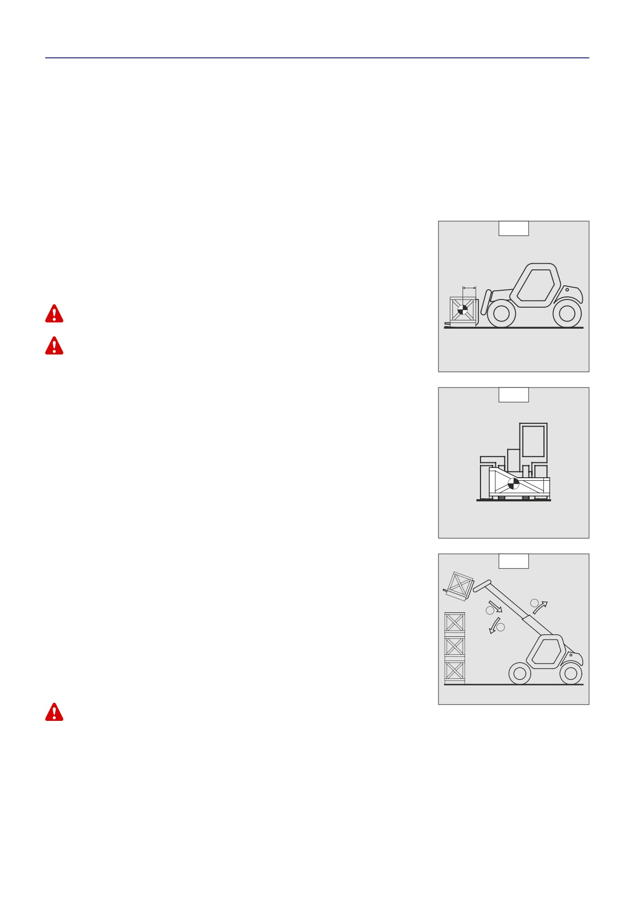
- Before taking up a load, you must know its mass and its centre of gravity.
- The load chart for your lift truck is valid for a load in which the longitudinal position of the
centre of gravity is 500 mm from the base of the forks (fig. B1). For a higher centre of
gravity, contact your dealer.
- For irregular loads, determine the transverse centre of gravity before any movement (fig.
500 mm
B2) and set it in the longitudinal axis of the lift truck.
It is forbidden to move a load heavier than the effective capacity defined on the lift truck load chart.
For loads with a moving centre of gravity (e.g. liquids), take account of the variations in the centre of
gravity in order to determine the load to be handled and be vigilant and take extra care to limit these
variations as far as possible.
B2
C - LONGITUDINAL STABILITY ALARM
- This device gives an indication of the lift truck’s longitudinal stability. Move the jib ver y
C
carefully when approaching the authorized load limit (see: 2 - DESCRIPTION: INSTRUMENTS
AND CONTROLS).
- Always watch this device during handling operations.
1
- W hen the device is in alert mode, it is forbidden to per form so-called «AGGRAVATING»
2
movements, these being:
3
A - Extending the jib.
B - Lowering the jib.
C - Tilt the carriage for wards.
- Per form movements to relieve aggravation in the following order (fig. C): if necessar y,
raise the jib (1), retract the jib as far as possible (2) and lower the jib (3) to release the
load.
The instrument reading may be erroneous when the steering is at its maximum limit or the rear axle
oscillated to its limit. Before lifting a load, make sure that the lift truck is not in either of these
situations.
1-14

D - TRANSVERSE ATTITUDE OF THE LIFT TRUCK
D1
Depending on the model of lift truck
The transverse attitude is the transverse slope of the chassis with respect to the
horizontal.
Raising the jib reduces the lift truck’s lateral stability. The transverse attitude must be set
with the jib in down position as follows:
1 - LIFT TRUCK WITHOUT SLOPE CORRECTOR USED ON TYRES
- Position the lift truck so that the bubble in the level is between the two lines (see: 2 -
DESCRIPTION: INSTRUMENTS AND CONTROLS).
2 - LIFT TRUCK WITH SLOPE CORRECTOR USED ON TYRES
- Correct the slope using the hydraulic control and verify the horizontality via the level. The
D2
bubble in the level must be between the two lines (see: 2 - DESCRIPTION: INSTRUMENTS
AND CONTROLS).
3 - LIFT TRUCK USED ON STABILIZERS
- Set the two stabilizers on the ground and raise the two front wheels of the lift truck (fig. D1).
- Correct the slope using the stabilizers (fig. D2) and make sure the truck is horizontal
by checking the level. The bubble of the level must be between the two lines (see: 2
- DESCRIPTION: INSTRUMENTS AND CONTROLS). In this position, the two front wheels
must be off the ground.
E - TAKING UP A LOAD ON THE GROUND
- Approach the lift truck perpendicular to the load, with the jib retracted and the forks in a horizontal position (fig. E1).
- Adjust the fork spread and centering in connection with the load (fig. E2) (optional solutions
exist, consult your dealer).
E1
- Never lift a load with a single fork.
Beware of the risks of trapping or squashing limbs when manually adjusting the forks.
- Move the lift truck for ward slowly (1) and bring the forks to stop in front of the load (fig.
E3), if necessar y, slightly lift the jib (2) while taking up the load.
- Bring the load into the transport position.
- Tilt the load far enough backwards to ensure stability (loss of load on braking or going
downhill).
FOR A NON-PALLETIZED LOAD
- Tilt the carriage (1) forwards and move the lift truck slowly forwards (2), to insert the fork
under the load (fig. E4) (block the load if necessar y).
- Continue to move the lift truck for wards (2) tilting the carriage (3) (fig. E4) backwards to
position the load on the forks and check the load’s longitudinal and lateral stability.
E2
E3
E4
1
2
2
1
3
1-15

F - TAKING UP AND LAYING A HIGH LOAD ON TYRES
F1
You must not raise the jib if you have not checked the transverse attitude of the lift truck (see:
INSTRUCTIONS FOR HANDLING A LOAD: D - TRANSVERSE ATTITUDE OF THE LIFT TRUCK).
REMINDER: Make sure that the following operations can be per formed with good visibility
2
(see: OPERATIONS INSTRUCTIONS UNLADEN AND LADEN: D - VISIBILITY).
1
TAKING UP A HIGH LOAD ON TYRES
- Ensure that the forks will easily pass under the load.
3
- Lift and extend the jib (1) (2) until the forks are level with the load, moving the lift truck (3)
for ward if necessar y (fig. F1), moving ver y slowly and carefully.
- Always think about keeping the distance necessar y to fit the forks under the load, between
the pile and the lift truck (fig. F1) and use the shortest possible length of jib.
- Stop the forks in front of the load by alternately extending and retracting the jib (1) or, if
necessar y, moving the lift truck for ward (2) (fig. F2). Put the handbrake on and set the
for ward/reverse selector to neutral.
F2
- Slightly lift the load (1) and incline the carriage (2) backwards to stabilize the load (fig. F3).
- Tilt the load sufficiently backwards to ensure its stability.
1
- W atch the longitudinal stability alarm (see: INSTRUCTIONS FOR HANDLING A LOAD: C
- LONGITUDINAL STABILITY ALARM). If it is overloaded, replace the load in the place from
which it was taken.
- If possible lower the load without shifting the lift truck. Lift the jib (1) to release the load,
retract (2) and lower the jib (3) to bring the load into the transport position (fig. F4).
2
- If this is not possible, back up the lift truck (1), manoeuvring very gently and carefully to
release the load. Retract (2) and lower the jib (3) to bring the load into the transport position
(fig. F5).
F3
2
1
F4
1
2
3
F5
2
3
1
1-16

LAYING A HIGH LOAD ON TYRES
F6
- Approach the load in the transport position in front of the pile (fig. F6).
- Put the handbrake on and set the for ward/reverse selector to neutral.
- Lift and extend the jib (1) (2) until the load is above the pile, while keeping an eye on the
longitudinal stability alarm (see: INSTRUCTIONS FOR HANDLING A LOAD: C - LONGITUDINAL
STABILITY ALARM). If necessar y, move the lift truck (3) for ward (fig. F7), driving ver y slowly
and carefully.
- Place the load in a horizontal position and lay it down on the pile by lowering and retracting
the jib (1) (2) in order to position the load correctly (fig. F8).
- If possible, release the fork by alternately retracting and raising the jib (1) (fig. F9). Then set
the forks into transport position.
- If this is not possible, reverse the lift truck (1) ver y slowly and carefully to release the
forks (fig. F10). Then set them into transport position.
F7
2
1
3
F8
1
2
F9
1
F10
1
1-17
G - TAKING UP AND LAYING A HIGH LOAD ON STABILIZERS
Depending on the model of lift truck
You must not raise the jib if you have not checked the transverse attitude of the lift truck (see: INSTRUCTIONS FOR HANDLING A LOAD: D - TRANSVERSE
ATTITUDE OF THE LIFT TRUCK).
REMINDER: Make sure that the following operations can be performed with good visibility (see: OPERATIONS INSTRUCTIONS UNLADEN
AND LADEN: D - VISIBILITY).
USING THE STABILIZERS
The stabilizers are used to optimise the lift truck’s lifting per formances (see: 2 - DESCRIPTION: INSTRUMENTS AND CONTROLS).
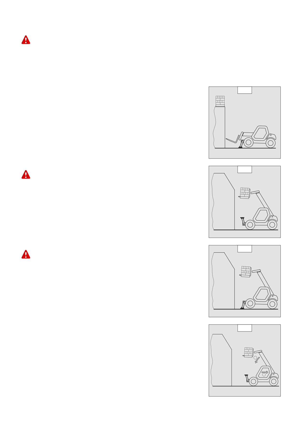
POSITION THE STABILIZERS WITH THE FORKS IN TRANSPORT POSITION (UNLADEN AND LADEN)
G1
- Set the forks in transport position in front of the elevation.
- Stay far enough away to have room for the jib to be raised.
- Put the handbrake on and put the gearshift lever into neutral.
- Set the two stabilizers on the ground and lift the two front wheels of the lift truck (fig. G1),
while maintaining its transverse stability.
RAISE THE STABILIZERS WITH THE FORKS IN TRANSPORT POSITION (UNLADEN AND LADEN)
- Raise both stabilizers fully and at the same time.
SETTING THE STABILIZERS WITH THE JIB UP (UNLADEN AND LADEN)
G2
This operation must be exceptional and performed with great care.
- Raise the jib and retract the telescopes completely.
- Set the lift truck in position in front of the elevation (fig. G2) moving ver y slowly and
carefully.
- Put the handbrake on and put the gearshift lever into neutral.
- M ove the stabilizers ver y slowly and gradually as soon as they are close to the ground or
in contact with it.
- Lower the two stabilizers and lift the two front wheels of the lift truck (fig. G3). During this
operation, transverse attitude must be permanently maintained: the bubble in the level
must be kept between the two lines.
SETTING THE STABILIZERS WITH THE JIB UP (UNLADEN AND LADEN)
G3
This operation must be exceptional and performed with great care.
- Keep the jib up and retract the telescopes completely (fig. G3).
- M ove the stabilizers ver y slowly and gradually as soon as they are in contact with the
ground and when they leave the ground. During this operation, the transverse attitude
must be permanently maintained: the bubble in the level must be kept between the two
lines.
- Raise both stabilizers completely.
- Release the parking brake and reverse the lift truck (1) ver y slowly and carefully, to
release it and lower the forks (2) into transport position (fig. G4).
G4
2
1
1-18
TAKING UP A HIGH LOAD ON STABILIZERS
G5
- Make sure the forks will fit easily under the load.
- Check the position of the lift truck with respect to the load and make a test run, if
necessar y, without taking the load.
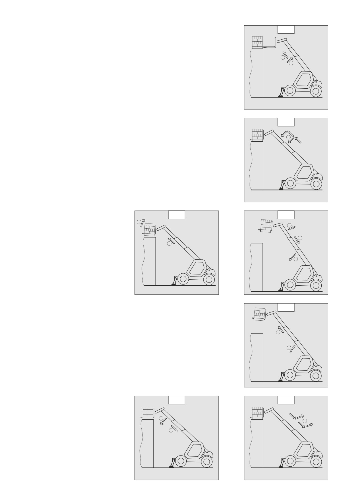
- Raise and extend the jib (1) (2) until the forks are at the level of the load (fig. G5).
2
- Block the forks in front of the load by alternately using the controls to extend and lower
1
the jib (1) (fig. G6).
- Lift the load slightly (1) and tilt the carriage (2) backwards to stabilise the load (fig. G7).
- M onitor the longitudinal stability alarm (see: INSTRUCTIONS FOR HANDLING A LOAD: C
- LONGITUDINAL STABILITY ALARM). If it is overloaded, set the load down in the place from
where it was taken.
- If possible lower the load without moving the lift truck. Raise the jib (1) to release the load,
retract (2) and lower the jib (3) to set the load into transport position (fig. G8).
G6
1
G7
G8
2
1
2
1
3
G9
LAYING A HIGH LOAD ON STABILIZERS
- Raise and extend the jib (1) (2) until the load is above the elevation (fig. G9), while
monitoring the longitudinal stability alarm (see: INSTRUCTIONS FOR HANDLING A LOAD: C
- LONGITUDINAL STABILITY ALARM).
2
- Position the load horizontally and release it by lowering and retracting the jib (1) (2) to
position the load correctly (fig. G10).
- Release the forks by alternating retracting and raising the jib (3) (fig. G11).
1
- If possible, set the jib in transport position without moving the lift truck.
G10
G11
1
3
2
1-19
H - TAKING UP AND LAYING DOWN A SUSPENDED LOAD
WARNING: Failure to follow the above instructions may lead the lift truck to loose stability and overturn.
MUST be used with a lift truck equipped with an operational hydraulic movement cut-out device.
CONDITIONS OF USE
- The length of the sling or the chain shall be as short as possible to limit swinging of the load.
- Lift the load vertically along its axis, never by pulling sideways or lengthways.
HANDLING WITHOUT MOVING THE LIFT TRUCK
- Whether on stabilisers or on tyres, the lateral attitude must not exceed 1 % and the longitudinal attitude must not exceed 5%, the
bubble of the level must be held at “0”.
- Ensure that the wind speed is not higher than 10 m/s.
- Ensure that there is no one between the load and the lift truck.
I - TRAVELLING WITH A SUSPENDED LOAD
- Before moving, inspect the terrain in order to avoid excessive slopes and cross-falls, bumps and potholes, or soft ground.
- Ensure that the wind speed is not higher than 10 m/s.
- The lift truck must not travel at more than 0.4 m/s (1.5 km/h, i.e., one quarter walking speed).
- Drive and stop the lift truck gently and smoothly to minimise swinging of the load.
- Carr y the load a few centimetres above the ground (max. 30 cm) the shortest possible jib length. Do not exceed the offset
indicated on the load chart. If the load begins to swing excessively, do not hesitate to stop and lower the jib to set down the
load.
- Before moving the lift truck, check the longitudinal stability alarm device (see: 2 - DESCRIPTION: INSTRUMENTS AND CONTROLS),
only the green LEDs and possibly the yellow LEDs should be lit.
- During transport, the lift truck operator must be assisted by a person on the ground (standing a minimum of 3 m from the load),
who will limit swinging of the load using a bar or a rope. Ensure that this person is always clearly in view.
- The lateral attitude must not exceed 5%, the bubble in the level must be kept between the two “MAX.” marks
- The longitudinal attitude must not exceed 15%, with the load facing uphill, and 10%, with the load facing downhill.
- The jib angle must not exceed 45°.
- If the first red LED of the longitudinal stability alarm device (see: 2 - DESCRIPTION: INSTRUMENTS AND CONTROLS) comes on
while travelling, gently bring the lift truck to a stop and stabilise the load. Retract the telescope to reduce the offset of the load.
1-20
PLATFORM OPERATING INSTRUCTIONS
For PLATFORM-fitted lift trucks
Installation of the platform on the lift truck is only possible if the shields “operating the platform” of the lift truck and the platform are identical (see: 2
- DESCRIPTION: OPERATING THE PLATFORM).
A - AUTHORISATION FOR USE
- Operation of the platform requires further authorisation in addition to that of the lift truck.
B - SUITABILITY OF THE TRUCK FOR USE
- MANITOU has ensured that this lift truck is suitable for use under the standard operating conditions defined in this operator’s
manual, with a STATIC test coefficient of 1.25 and a DYNAMIC test coefficient of 1.1, as specified in harmonised standard
EN 280 for “mobile elevating work platforms”.
- Before commissioning, the company manager must make sure that the platform is appropriate for the work to be done, and
per form certain tests (in accordance with current legislation).
C - PRECAUTIONS WHEN USING THE PLATFORM
- Wear clothes suited for operating the platform, avoid loose clothes.
- Never operate the platform when hands or feet are wet or soiled with greasy substances.
- Always pay attention when using the platform. Do not listen to the radio or music using headphones or earphones.
- For increased comfort, adopt the correct position at the platform’s operator station.
- The platform’s guard rail exempts the operator from wearing a safety harness under normal operating conditions. As a result, you
are responsible deciding whether to wear a safety harness.
- The controls must not be used for any other than their intended purpose (e.g. getting in and out of the lift truck, coat hanger etc.).
- Safety helmets must be worn.
- The operator must always be in the normal operator’s position. It is prohibited to have arms or legs, or generally any part of the
body, protruding from the basket.
- Ensure that any materials loaded onto the platform (pipes, cables, containers, etc.) cannot fall out. Do not pile these materials
to the point where it is necessar y to step over them.
D - USING THE PLATFORM
- However experienced they may be, operators must acquaint themselves with the emplacement and operation of all control
instruments prior to operating the platform.
- Check before operating that the platform has been correctly assembled and locked onto the lift truck.
- Check before operating the platform that the access gate has been properly locked.
- The platform should be operated in an area free of any obstructions or danger when it is lowered to the ground.
- The operator using the platform must be aided on the ground by a person with adequate training.
- You should stay within the limits set out in the platform load chart.
- The lateral stresses are limited pressure (see: 2 - DESCRIPTION: CHARACTERISTICS).
- It is strictly forbidden to hand a load from the platform or the lift truck jib without a specially designed attachment (see: INSTRUCTIONS
FOR HANDLING A LOAD: H - TAKING UP AND LAYING DOWN A SUSPENDED LOAD).
- The platform cannot be used as a crane or a lift for permanently transporting people or materials, nor as jacks or supports.
- The lift truck must not be moved with one (or more) person(s) in the platform.
- It is forbidden to transport people on the platform using the hydraulic controls in the lift truck’s driver’s cab (except in case of rescue).
- The operator must not get in or out of the platform when it is not on ground level (jib retracted and in the down position).
- The platform must not be fitted with attachments that increase the unit’s wind load.
- Do not use ladders or improvised structures in the platform to gain extra height.
- Do not climb onto the sides of the platform to gain extra height.
E - ENVIRONMENT
DISTANCE ABOVE THE
NOMINAL VOLTAGE
GROUND OR THE FLOOR
Operating the platform close to electricity cables is forbidden. Maintain the specified
IN METRES
safe distances.
50 < U < 1000
2,30 M
1000 < U < 30000
2,50 M
30000 < U < 45000
2,60 M
45000 < U < 63000
2,80 M
63000 < U < 90000
3,00 M
90000 < U < 150000
3,40 M
150000 < U < 225000
4,00 M
225000 < U < 400000
5,30 M
400000 < U < 750000
7,90 M
1-21

Operation of the platform is strictly forbidden in the event of wind speeds of over 45 km/h.
- The following scale is given for an empiric evaluation of the wind speed:
BEAUFORT scale (wind speed at a height of 10 m from flat ground)
Speed
Speed
Speed
Force
Type of wind
Effects on Land
Sea condition
(knots)
(kph)
(m/s)
0
Calm
0 - 1
0 - 1
< 0,3
Smoke rises vertically.
Sea like a mirror.
1
Light air
1 - 3
1 - 5
0,3 - 1,5
The wind bends the smoke.
Ripples but without foam crests.
The wind can be felt on the face,
2
Light breeze
4 - 6
6 - 11
1,6 - 3,3
Small but evident wavelets.
shakes the leaves.
Gentle
The wind continuously shakes the
Large wavelets Perhaps scattered
3
7 - 10
12 - 19
3,4 - 5,4
breeze
leaves and twigs.
white horses.
Moderate
The wind raises dust and scraps of
Small waves. Fairly frequent white
4
11 - 16
20 - 28
5,5 - 7,9
breeze
paper, shakes the twigs.
horses.
Small waves form on inland waters.
5
Fresh breeze
17 - 21
29 - 38
8 - 10,7
Leafy shrubs sway.
Moderate waves, many white
horses.
Shakes thick branches, metal wires
Strong
Large waves begin to form, white
6
22 - 27
39 - 49
10,8 - 13,8
hum, it becomes difficult to keep an
breeze
foam crests, probably spray.
umbrella open.
Sea heaps up and white foam blown
Whole trees sway, it is difficult to
7
Near gale
28 - 33
50 - 61
13,9 - 17,1
in streaks along the direction of the
walk against the wind.
wind.
Breaks the branches of trees, it is
Moderately high waves, crests begin
8
Gale
34 - 40
62 - 74
17,2 - 20,7
almost impossible to walk against
to break into spindrift.
the wind.
High waves. Dense foam along
Causes slight damage to buildings
the direction of the wind. Crests of
9
Strong gale
41 - 47
75 - 88
20,8 - 24,4
(stacks, tiles, etc..).
waves begin to roll over. Spray may
affect visibility.
Rare inland, uproots trees, causes
Ver y high waves with long overhanging
10
Storm
48 - 55
89 - 102
24,5 - 28,4
considerable damage to buildings.
crests. Visibility affected.
Exceptionally high waves that may
Violent
Ver y rare,
causes extensive
11
56 - 63
103 - 117
28,5 - 32,6
hide medium sized ships. Visibility
storm
devastation.
affected.
The air is filled with foam and
spray. Sea completely white with
12
Hurricane
64 +
118 +
32,7 +
Causes ver y serious catastrophes.
driving spray. Visibility ver y seriously
affected.
F - MAINTENANCE
Your platform must be periodically inspected to ensure its continued compliance. The inspection frequency is defined by the current legislation in the
country in which the platform is used.
1-22
INSTRUCTIONS FOR USING THE RADIO-CONTROL
For lift trucks with RC radio control
HOW TO USE THE RADIO-CONTROL
SAFETY INSTRUCTIONS
- This radio-control consists of electronic and mechanical safety elements. It cannot receive commands from another transmitter
because the internal encoding is unique to each radio-control.
If it is used improperly or incorrectly, there is a risk of danger to:
- The physical and mental health of the user or others.
- The lift truck and other neighbouring items.
Everyone working with this radio-control:
- Must be qualified in line with current regulations and therefore appropriately trained.
- Must follow this instruction manual as closely as possible.
- The system is used to control the lift truck remotely via radio waves. Commands are also transmitted if the lift truck is out of sight
(behind an obstacle or a building for example), this is why:
• After stopping the truck and removing the key button (only possible when it is stationar y), always place the transmitter in
a safe, dr y place.
• Before per forming any installation, ser vicing or repair work, always switch off power sources (in particular, electric welding
devices and electric head units on hydraulic distributors must be disconnected at each section).
• Never remove or alter the safety devices (such as the hand-guard frame, key, emergency stop button, etc.).
Never drive the lift truck if it is not continuously and perfectly within view of the operator!
- Before leaving the transmitter, the operator must make sure that it cannot be used by an unauthorized third person: either by
removing the key button from the transmitter or locking it in an inaccessible place.
- The user must ensure that the instruction manual is accessible at all times and that operators have read and understood it.
INSTRUCTIONS
- Take up position in a stable place with no risk of slipping.
- Before using the transmitter, make sure there is nobody within the working area.
- Only use the transmitter with its carr ying device or installed correctly on the platform.
When you remove the transmitter, remove the accumulator and key button so that it cannot be used accidentally or deliberately by anyone else.
PROTECTIVE DEVICES
- The lift truck will be immobilised within 450 milliseconds (approx. 0.5 second) at most:
• If the transmitter emergency stop button (50 milliseconds), or the one on the lift is pressed.
• If the transmission distance of the radio waves is exceeded.
• If the transmitter is faulty.
• If an inter fering radio signal is received from elsewhere.
• If the accumulator is removed from its housing in the transmitter.
• If the accumulator reaches the end of its autonomy.
• If the transmitter is switched off by turning the key button to stop.
- These protective devices are provided for the safety of personnel and property and must never be altered, removed or bypassed
in any way whatsoever!
- The hand-guard frame prevents external action on a manipulator (if the transmitter falls, for example, or if the operator leans on
a guard-rail).
- An electronic safety device prevents radio transmission from being initiated if the manipulators are not mechanically and electrically
at rest and if the internal combustion engine speed selector is not set to idle.
In an emergency, press the transmitter emergency stop button immediately ; then follow the manual’s instructions (see: 2 - DESCRIPTION: INSTRUMENTS
AND CONTROLS).
1-23
MAINTENANCE INSTRUCTIONS OF THE LIFT TRUCK
GENERAL INSTRUCTIONS
- Ensure the area is sufficiently ventilated before starting the lift truck.
- W ear clothes suitable for the maintenance of the lift truck, avoid wearing jeweller y and loose clothes. Tie and protect your hair,
if necessar y.
- Stop the I.C. engine and remove the ignition key, when an inter vention is necessar y.
- Read the operator’s manual carefully.
- Carr y out all repairs immediately, even if the repairs concerned are minor.
- Repair all leaks immediately, even if the leak concerned is minor.
- M ake sure that the disposal of process materials and of spare parts is carried out in total safety and in a ecological way.
- Be careful of the risk of burning and splashing (exhaust, radiator, I.C. engine, etc.).
MAINTENANCE
- Perform the periodic service (see: 3 - MAINTENANCE) to keep your lift truck in good working conditions. Failure to perform the periodic
ser vice may cancel the contractual guarantee.
MAINTENANCE LOGBOOK
- The maintenance operations carried out in accordance with the recommendations given in part: 3 - MAINTENANCE and the other
inspection, ser vicing or repair operations or modifications per formed on the lift truck or its attachments shall be recorded in a
maintenance logbook. The entr y for each operation shall include details of the date of the works, the names of the individuals or
companies having per formed them, the type of operation and its frequency, if applicable. The part numbers of any lift truck items
replaced shall also be indicated.
LUBRICANT AND FUEL LEVELS
- Use the recommended lubricants (never use contaminated lubricants).
- Do not fill the fuel tank when the I.C. engine is running.
- Only fill up the fuel tank in areas specified for this purpose.
- Do not fill the fuel tank to the maximum level.
- Do not smoke or approach the lift truck with a flame, when the fuel tank is open or is being filled.
HYDRAULIC
- Any work on the load handling hydraulic circuit is forbidden except for the operations described in part: 3 - MAINTENANCE.
- Do not attempt to loosen unions, hoses or any hydraulic component with the circuit under pressure.
BALANCING VALVE: It is dangerous to change the setting and remove the balancing valves or safety valves which may be fitted to your lift truck cylinders.
These operations must only be performed by approved personnel (consult your dealer).
The HYDRAULIC ACCUMULATORS that may be fitted on your lift truck are pressurized units. Removing these accumulators and their pipework is a
dangerous operation and must only be performed by approved personnel (consult your dealer).
ELECTRICITY
- Do not short-circuit the starter relay to start the IC engine. If the forward/reverse selector is not in neutral and the parking brake is
not engaged, the lift truck may suddenly start to move.
- Do not drop metallic items on the batter y.
- Disconnect the batter y before working on the electrical circuit.
1-24
WELDING
- Disconnect the batter y before any welding operations on the lift truck.
- When carr ying out electric welding work on the lift truck, connect the negative cable from the equipment directly to the part being
welded, so as to avoid high tension current passing through the alternator.
- Never carr y out welding or work which gives off heat on an assembled tyre. The heat would increase the pressure which could
cause the tyre to explode.
- If the lift truck is equipped with an electronic control unit, disconnect this before starting to weld, to avoid the risk of causing
irreparable damage to electronic components.
WASHING THE LIFT TRUCK
- Clean the lift truck or at least the area concerned before any inter vention.
- Remember to close and lock all accesses to the lift truck (doors, windows, cowls…).
- During washing, avoid the articulations and electrical components and connections.
- If necessar y, protect against penetration of water, steam or cleaning agents, components susceptible of being damaged,
particularly electrical components and connections and the injection pump.
- Clean the lift truck of any fuel, oil or grease trace.
FOR ANY INTERVENTION OTHER THAN REGULAR MAINTENANCE, CONSULT YOUR DEALER.
1-25
IF THE LIFT TRUCK IS NOT TO BE USED FOR A LONG TIME
INTRODUCTION
The following recommendations are intended to prevent the lift truck from being damaged when it is withdrawn from ser vice for an
extended period.
For these operations, we recommend the use of a MANITOU protective product, reference 603726.
Instructions for using the product are given on the packaging.
Procedures to follow if the lift truck is not to be used for a long time and for starting it up again afterwards must be performed by your dealership.
PREPARING THE LIFT TRUCK
- Clean the lift truck thoroughly.
- Check and repair any leakage of fuel, oil, water or air.
- Replace or repair any worn or damaged parts.
- Wash the painted sur faces of the lift truck in clear and cold water and wipe them.
- Touch up the paintwork if necessar y.
- Shut down the lift truck (see: OPERATING INSTRUCTIONS UNLADEN AND LADEN).
- Make sure the jib cylinder rods are all in retracted position.
- Release the pressure in the hydraulic circuits.
PROTECTING THE I.C. ENGINE
- Fill the tank with fuel (see: 3 - MAINTENANCE: A - DAILY OR EVERY 10 HOURS SERVICE).
- Empty and replace the cooling liquid (see: 3 - MAINTENANCE: F - EVERY 2000 HOURS SERVICE).
- Leave the I.C. engine running at idling speed for a few minutes, then switch off.
- Replace the I.C. engine oil and oil filter (see: 3 - MAINTENANCE: D - EVERY 500 HOURS SERVICE).
- Add the protective product to the engine oil.
- Run the I.C. engine for a short time so that the oil and cooling liquid circulate inside.
- Disconnect the batter y and store it in a safe place away from the cold, after charging it to a maximum.
- Remove the injectors and spray the protective product into each cylinder for two seconds with the piston in low neutral position.
- Turn the crankshaft once slowly and refit the injectors (see I.C. engine REPAIR MANUAL).
- Remove the intake hose from the manifold or turbocharger and spray the protective product into the manifold or turbocharger.
- Cap the intake manifold or turbocharger hole with waterproof adhesive tape.
- Remove the exhaust pipe and spray the protective product into the exhaust manifold or turbocharger.
- Refit the exhaust pipe and block the outlet with waterproof adhesive tape.
NOTE: The spray time is noted on the product packaging and must be increased by 50 % for turbo engines.
- Open the filler plug, spray the protective product around the rocker arm shaft and refit the filler plug.
- Cap the fuel tank using waterproof adhesive tape.
- Remove the drive belts and store them in a safe place.
- Disconnect the engine cut-off solenoid on the injection pump and carefully insulate the connection.
PROTECTING THE LIFT TRUCK
- Set the lift truck on axle stands so that the tyres are not in contact with the ground and release the handbrake.
- Protect cylinder rods which will not be retracted, from corrosion.
- Wrap the tyres.
NOTE: If the lift truck is to be stored outdoors, cover it with a waterproof tarpaulin.
1-26
BRINGING THE LIFT TRUCK BACK INTO SERVICE
- Remove the waterproof adhesive tape from all the holes.
- Refit the intake hose.
- Refit and reconnect the batter y.
- Remove the protection from the cylinder rods.
- Per form the daily ser vice (see: 3 - MAINTENANCE: A - DAILY OR EVERY 10 HOURS SERVICE).
- Put the handbrake on and remove the axle stands.
- Empty and replace the fuel and replace the fuel filter (see: 3 - MAINTENANCE: D - EVERY 500 HOURS SERVICE).
- Refit and set the tension in the drive belts (see: 3 - MAINTENANCE: C - EVERY 250 HOURS SERVICE).
- Turn the I.C. engine using the starter, to allow the oil pressure to rise.
- Reconnect the engine cut-off solenoid.
- Lubricate the lift truck completely (see: 3 - MAINTENANCE: SERVICING SCHEDULE).
Make sure the area is adequately ventilated before starting up the lift truck.
- Start up the lift truck, following the safety instructions and regulations (see: OPERATING INSTRUCTIONS UNLADEN AND LADEN).
- Run all the jib’s hydraulic movements, concentrating on the ends of travel for each cylinder.
1-27

TABLE OF CONTENTS
« EC» DECLARATION OF CONFORMITY
2-4
IDENTIFICATION OF THE LIFT TRUCK
2-6
CHARACTERISTICS
MT 728 Série D-E3
2-8
CHARACTERISTICS
MT 732 Série D-E3
2-10
CHARACTERISTICS
MT 928 Série D-E3
2-12
CHARACTERISTICS
MT 932 Série D-E3
2-14
CHARACTERISTICS
MT 1030 S Série 4-E3
2-16
CHARACTERISTICS
MT 1030 S Turbo Série 4-E3
2-18
FRONT AND REAR TIRES
2-20
DIMENSIONS AND LOAD CHART MT 728 Série D-E3
2-24
DIMENSIONS AND LOAD CHART MT 732 Série D-E3
2-26
DIMENSIONS AND LOAD CHART MT 928 Série D-E3
2-28
DIMENSIONS AND LOAD CHART MT 932 Série D-E3
2-30
DIMENSIONS AND LOAD CHART MT 1030 S Série 4-E3
MT 1030 S Turbo Série 4-E3
2-32
INSTRUMENTS AND CONTROLS
2-34
TOWING PIN AND HOOK
2-58
DESCRIPTION AND USE OF THE OPTIONS
2-60
2-3

IDENTIFICATION OF THE LIFT TRUCK
As our policy is to promote a constant improvement of our products, our range of telescopic lift trucks may undergo certain
modifications, without obligation for us to advise our customers.
When you order parts, or when you require any technical information, always specify:
NOTE: For the owner’s convenience, it is recommended that a note of these numbers is made in the spaces provided, at the time
of the deliver y of the lift truck.
LIFT TRUCK MANUFACTURER’S PLATE (FIG. A)
A
- Model
MANITOU BF 44158 ANCENIS CEDEX FRANCE
- Series
MODELE
MODELLO
SERIE
SERIE
MODEL
MODELO
SERIES
SERIE
- Serial Nr
Année de fabrication
N° de sérieSerial Nr
Numero di serieNúmero de serie
Year of manufactureAnno di fabbricazione
- Chassis Nr
Año de fabricacion
Masse à videUnladen mass
Massa a vuotoMasa en vacio
- Year of manufacture
Puissance ISO/TR14396
kg
Power ISO/TR14396Potenza ISO/TR14396
Potencia ISO/TR14396
Numéro d'homologation
kW
Homologation numberNumero d'omologazione
Contraseña homologacion
Vertical max. effort (on trailer hook)
Effort vertical max. (sur accrochage remorque)
For any further technical information regarding your lift truck refer to chapter:
2 -
Carico max. verticale (sul gancio di traino)
Esfuerzo vertical max. (sobre el gancho de remolque)
Capacité maxi nominaleNominal maximum capacity
daN
Capacità maxi nominaleCapacidad máximo nominal
DESCRIPTION: CHARACTERISTICS.
Tyre pressure (Bar)
Pression des pneumatiques (Bar)
kg
Pressione per pneumatici (Bar)Presion de los neumáticos (Bar)
Effort de traction
Avant Anteriore
Arrière Posteriore
Tractive effort
Front
Adelante Rear
Trasero
Forza di traino
Esfuerzo de traccion
daN
N°283688
I.C. ENGINE (FIG. B)
B
- I.C. engine Nr
GEAR BOX (FIG. C)
C
- Type
- MANITOU reference
- Serial Nr
ANGLE GEARBOX (FIG. D)
D
- Type
- MANITOU reference
- Serial Nr
2-6

FRONT AXLE (FIG. E)
E
- Type
- Serial Nr
- MANITOU reference
REAR AXLE (FIG. F)
F
- Type
- Serial Nr
- MANITOU reference
CAB (FIG. G)
G
- Type
- Serial Nr
BOOM (FIG. H)
H
- MANITOU reference
- Date of manufacture
PLATE MANUFACTURER OF THE ATTACHMENT (FIG. I)
I
- Model
MANITOU BF
44158 ANCENIS CEDEX
- Serial Nr
FRANCE
MODELE
- Year of manufacture
N$ dans la série
Année fabrication
Masse à vide
kg
C d G / Tablier
A vide / En charge : mm
Cap. Nominale
Pression de service
AVERTISSEMENT : RESPECTEZ
LA CAPACITE DE L'ENSEMBLE
"CHARIOT ET EQUIPEMENT"
N$241415
2-7

CHARACTERISTICS
MT 728 Série D-E3
I.C. ENGINE
Type
Fuel
Number of cylinders
Suction
Injection system
Ignition sequence
Capacity
cm3
Bore and stroke
mm
Compression ratio
Nominal rating loaded
rpm
Rating slow unladen
rpm
Max. rating unladen
rpm
Power ISO/TR 14396
cv- kW
Power SAE J 1995
cv- kW
Maximum torque ISO/TR 14396
Nm
Air cleaner
μm
Type of cooling
Fan
TRANSMISSION
Gear box
Type
For ward/reverse selector
Torque converter
Number of for ward speeds
Number of reverse speeds
Angle gear box
Front axle
Differential
Rear axle
Differential
Drive wheels
Switch for 2/4 drive wheels
Front tyres
Size
Pressure
bar
Rear tyres
Size
Pressure
bar
ELECTRIC CIRCUIT
Standard
Batter y
Option
Alternator
Type
Starter
Type
BRAKE CIRCUIT
Ser vice brake
Type of brake
Type of control
Parking brake
Type of brake
Type of control
SOUND AND VIBRATION
Level of sound pressure in the driver’s cab LpA
dB
(according to standard NF EN 12053)
Level of sound power ensured in the LwA environment
dB
(according to directive 2000/14/EC modified by directive 2005/88/EC)
Average weighted acceleration on driver’s body
m/s2
(according to standard NF EN 13059)
The average weighted acceleration transmitted to the driver’s hand/arm system
m/s2
(according to standard ISO 5349-2)
2-8

HYDRAULIC CIRCUIT
Hydraulic pump
Type
Capacity
cm3
Max. rating capacity unladen
l/mn
Flow rate at 1600 rpm
l/mn
Filtration
Return
μm
Suction
μm
Maximum ser vice pressure
bar
Telescoping circuit
bar
Lifting circuit
bar
Tilt circuit
bar
Attachment circuit
bar
Steering circuit
bar
HYDRAULIC MOVEMENTS
Longitudinal stability alarm device
Lifting motions (boom retracted)
Unladen lifting
s - m/mn
Laden lifting
s - m/mn
Unladen lowering
s - m/mn
Laden lowering
s - m/mn
Telescoping motions (boom raised)
Unladen extending
s - m/mn
Laden extending
s - m/mn
Unladen retracting
s - m/mn
Laden retracting
s - m/mn
Tilting movements
Unladen digging
s - °/s
For ward tilting unladen
s - °/s
SPECIFICATIONS AND WEIGHTS
Speed of movement for lift truck in standard configuration on flat
ground (except particular conditions)
Front unladen
1
km/h
2
km/h
3
km/h
4
km/h
Rear unladen
1
km/h
2
km/h
3
km/h
4
km/h
Standard attachment
Weight of equipment
kg
Weight of forks (each one)
kg
Rated capacity with standard attachment
kg
Tipping load at maximum reach on tyres
kg
Distance from the centre of gravity from the load to the lug of the forks
mm
Standard lifting height
mm
Lift truck weight without attachment
kg
Lift truck weight with standard attachment
Unladen
kg
At rated load
kg
Weight per axle with standard attachment (transport position)
Front unladen
kg
Rear unladen
kg
Front rated load
kg
Rear rated load
kg
Weight per axle with standard attachment (boom extended)
Front rated load
kg
Rear rated load
kg
Contact pressure on the ground for the whole sur face of each
kg/cm2
stabilizer at maximum load when tilting
Drag strain on the coupling hook
Unladen (sliding)
daN
At rated load (transmission setting)
daN
Pull strain with open carrier (according to standard ISO 8313)
daN
2-9

CHARACTERISTICS
MT 732 Série D-E3
I.C. ENGINE
Type
PERKINS 1104D-44T NL38857
Fuel
Diesel
Number of cylinders
4 in line
Suction
Turbocharged
Injection system
Direct
Ignition sequence
1,3,4,2
Capacity
cm3
4400
Bore and stroke
mm
105 x 127
Compression ratio
18,2:1
Nominal rating loaded
rpm
2200
Rating slow unladen
rpm
930
Max. rating unladen
rpm
2380
Power ISO/TR 14396
cv- kW
95 - 70
Power SAE J 1995
cv- kW
95 - 70
Maximum torque ISO/TR 14396
Nm
392 to 1400 rpm
Air cleaner
μm
3
Type of cooling
By water
Fan
Puller
TRANSMISSION
Gear box
TURNER
Type
Mechanical
For ward/reverse selector
Electro-hydraulic
Torque converter
SACHS
Number of for ward speeds
4
Number of reverse speeds
4
Angle gear box
TURNER
Front axle
DANA
Differential
Limited slip
Rear axle
DANA
Differential
Without locking
Drive wheels
4RM Permanent
Switch for 2/4 drive wheels
No
Front tyres
MICHELIN
Size
400-80 - 24 156A8 IND TL PCL
Pressure
bar
3
Rear tyres
MICHELIN
Size
400-80 - 24 156A8 IND TL PCL
Pressure
bar
3
ELECTRIC CIRCUIT
Standard
12 V - 110 Ah - 750 A EN
Batter y
Option
12 V - 145 Ah - 1000 A EN
Alternator
12 V - 85 A
Type
Denso Ai115
Starter
12 V - 3,2 kW
Type
AZE
BRAKE CIRCUIT
Ser vice brake
Non-ser vo hydraulic brake
Type of brake
Multidisk brake immersed in oil
Type of control
Foot-operated for the front and rear axles
Parking brake
Mechanical
Type of brake
Disk on gear-box output
Type of control
Manual
SOUND AND VIBRATION
Level of sound pressure in the driver’s cab LpA
dB
78
(according to standard NF EN 12053)
Level of sound power ensured in the LwA environment
104 (measured)
dB
(according to directive 2000/14/EC modified by directive 2005/88/EC)
105 (ensured)
Average weighted acceleration on driver’s body
m/s2
(according to standard NF EN 13059)
The average weighted acceleration transmitted to the driver’s hand/arm system
m/s2
< 2,5
(according to standard ISO 5349-2)
2-10

HYDRAULIC CIRCUIT
Hydraulic pump
Type
Gear type with flow divider
Capacity
cm3
1st chamber
2nd chamber
Max. rating capacity unladen
l/mn
22
22
Flow rate at 1600 rpm
l/mn
52
52
Filtration
35
35
Return
μm
Suction
μm
15
15
Maximum ser vice pressure
bar
125
125
Telescoping circuit
bar
250
Lifting circuit
bar
190 / 250
Tilt circuit
bar
250 / 250
Attachment circuit
bar
250 / 190
Steering circuit
bar
250
Circuit direction
bar
140
HYDRAULIC MOVEMENTS
Longitudinal stability alarm device
Electronic
Lifting motions (boom retracted)
Unladen lifting
s - m/mn
7,2 - 37,6
Laden lifting
s - m/mn
7,2 - 37,6
Unladen lowering
s - m/mn
5,5 - 49,2
Laden lowering
s - m/mn
5,8 - 46,6
Telescoping motions (boom raised)
Unladen extending
s - m/mn
6,5 - 24,9
Laden extending
s - m/mn
6,5 - 24,9
Unladen retracting
s - m/mn
5,4 - 30,0
Laden retracting
s - m/mn
5,9 - 27,5
Tilting movements
Unladen digging
s - °/s
2,9 - 43,3
For ward tilting unladen
s - °/s
2,8 - 44,9
SPECIFICATIONS AND WEIGHTS
Speed of movement for lift truck in standard configuration on flat
ground (except particular conditions)
Front unladen
1
km/h
4,4
2
km/h
7,1
3
km/h
15,0
4
km/h
26,7
Rear unladen
1
km/h
4,4
2
km/h
7,1
3
km/h
15,0
4
km/h
26,7
Standard attachment
TFF
Weight of equipment
kg
165
Weight of forks (each one)
kg
67,5
Rated capacity with standard attachment
kg
3200
Tipping load at maximum reach on tyres
kg
1620
Distance from the centre of gravity from the load to the lug of the forks
mm
500
Standard lifting height
mm
6900
Lift truck weight without attachment
kg
7030
Lift truck weight with standard attachment
Unladen
kg
7330
At rated load
kg
10530
Weight per axle with standard attachment (transport position)
Front unladen
kg
3160
Rear unladen
kg
4170
Front rated load
kg
9060
Rear rated load
kg
1470
Weight per axle with standard attachment (boom extended)
Front rated load
kg
7830
Rear rated load
kg
750
Contact pressure on the ground for the whole sur face of each
kg/cm2
-
stabilizer at maximum load when tilting
Drag strain on the coupling hook
Unladen (sliding)
daN
6155
At rated load (transmission setting)
daN
9280
Pull strain with open carrier (according to standard ISO 8313)
daN
7400
2-11

CHARACTERISTICS
MT 928 Série D-E3
I.C. ENGINE
Type
Fuel
Number of cylinders
Suction
Injection system
Ignition sequence
Capacity
cm3
Bore and stroke
mm
Compression ratio
Nominal rating loaded
rpm
Rating slow unladen
rpm
Max. rating unladen
rpm
Power ISO/TR 14396
cv- kW
Power SAE J 1995
cv- kW
Maximum torque ISO/TR 14396
Nm
Air cleaner
μm
Type of cooling
Fan
TRANSMISSION
Gear box
Type
For ward/reverse selector
Torque converter
Number of for ward speeds
Number of reverse speeds
Angle gear box
Front axle
Differential
Rear axle
Differential
Drive wheels
Switch for 2/4 drive wheels
Front tyres
Size
Pressure
bar
Rear tyres
Size
Pressure
bar
ELECTRIC CIRCUIT
Standard
Batter y
Option
Alternator
Type
Starter
Type
BRAKE CIRCUIT
Ser vice brake
Type of brake
Type of control
Parking brake
Type of brake
Type of control
SOUND AND VIBRATION
Level of sound pressure in the driver’s cab LpA
dB
(according to standard NF EN 12053)
Level of sound power ensured in the LwA environment
dB
(according to directive 2000/14/EC modified by directive 2005/88/EC)
Average weighted acceleration on driver’s body
m/s2
(according to standard NF EN 13059)
The average weighted acceleration transmitted to the driver’s hand/arm system
m/s2
(according to standard ISO 5349-2)
2-12

HYDRAULIC CIRCUIT
Hydraulic pump
Type
Capacity
cm3
Max. rating capacity unladen
l/mn
Flow rate at 1600 rpm
l/mn
Filtration
Return
μm
Suction
μm
Maximum ser vice pressure
bar
Telescoping circuit
bar
Lifting circuit
bar
Tilt circuit
bar
Attachment circuit
bar
Steering circuit
bar
HYDRAULIC MOVEMENTS
Longitudinal stability alarm device
Lifting motions (boom retracted)
Unladen lifting
s - m/mn
Laden lifting
s - m/mn
Unladen lowering
s - m/mn
Laden lowering
s - m/mn
Telescoping motions (boom raised)
Unladen extending
s - m/mn
Laden extending
s - m/mn
Unladen retracting
s - m/mn
Laden retracting
s - m/mn
Tilting movements
Unladen digging
s - °/s
For ward tilting unladen
s - °/s
SPECIFICATIONS AND WEIGHTS
Speed of movement for lift truck in standard configuration on flat
ground (except particular conditions)
Front unladen
1
km/h
2
km/h
3
km/h
4
km/h
Rear unladen
1
km/h
2
km/h
3
km/h
4
km/h
Standard attachment
Weight of equipment
kg
Weight of forks (each one)
kg
Rated capacity with standard attachment
kg
Tipping load at maximum reach on tyres
kg
Distance from the centre of gravity from the load to the lug of the forks
mm
Standard lifting height
mm
Lift truck weight without attachment
kg
Lift truck weight with standard attachment
Unladen
kg
At rated load
kg
Weight per axle with standard attachment (transport position)
Front unladen
kg
Rear unladen
kg
Front rated load
kg
Rear rated load
kg
Weight per axle with standard attachment (boom extended)
Front rated load
kg
Rear rated load
kg
Contact pressure on the ground for the whole sur face of each
kg/cm2
stabilizer at maximum load when tilting
Drag strain on the coupling hook
Unladen (sliding)
daN
At rated load (transmission setting)
daN
Pull strain with open carrier (according to standard ISO 8313)
daN
2-13

CHARACTERISTICS
MT 932 Série D-E3
I.C. ENGINE
Type
PERKINS 1104D-44T NL38857
Fuel
Diesel
Number of cylinders
4 in line
Suction
Turbocharged
Injection system
Direct
Ignition sequence
1,3,4,2
Capacity
cm3
4400
Bore and stroke
mm
105 x 127
Compression ratio
18,2:1
Nominal rating loaded
rpm
2200
Rating slow unladen
rpm
930
Max. rating unladen
rpm
2380
Power ISO/TR 14396
cv- kW
95 - 70
Power SAE J 1995
cv- kW
95 - 70
Maximum torque ISO/TR 14396
Nm
392 to 1400 rpm
Air cleaner
μm
3
Type of cooling
By water
Fan
Puller
TRANSMISSION
Gear box
TURNER
Type
Mechanical
For ward/reverse selector
Electro-hydraulic
Torque converter
SACHS
Number of for ward speeds
4
Number of reverse speeds
4
Angle gear box
TURNER
Front axle
DANA
Differential
Limited slip
Rear axle
DANA
Differential
Without locking
Drive wheels
4RM Permanent
Switch for 2/4 drive wheels
No
Front tyres
MICHELIN
Size
400-80 - 24 156A8 IND TL PCL
Pressure
bar
3
Rear tyres
MICHELIN
Size
400-80 - 24 156A8 IND TL PCL
Pressure
bar
3
ELECTRIC CIRCUIT
Standard
12 V - 110 Ah - 750 A EN
Batter y
Option
12 V - 145 Ah - 1000 A EN
Alternator
12 V - 85 A
Type
Denso Ai115
Starter
12 V - 3,2 kW
Type
AZE
BRAKE CIRCUIT
Ser vice brake
Non-ser vo hydraulic brake
Type of brake
Multidisk brake immersed in oil
Type of control
Foot-operated for the front and rear axles
Parking brake
Mechanical
Type of brake
Disk on gear-box output
Type of control
Manual
SOUND AND VIBRATION
Level of sound pressure in the driver’s cab LpA
dB
77
(according to standard NF EN 12053)
Level of sound power ensured in the LwA environment
104 (measured)
dB
(according to directive 2000/14/EC modified by directive 2005/88/EC)
105 (ensured)
Average weighted acceleration on driver’s body
m/s2
(according to standard NF EN 13059)
The average weighted acceleration transmitted to the driver’s hand/arm system
m/s2
< 2,5
(according to standard ISO 5349-2)
2-14

HYDRAULIC CIRCUIT
Hydraulic pump
Type
Gear pump with flow divider
1st casing
2nd casing
Capacity
cm3
22
22
Max. rating capacity unladen
l/mn
52
52
Flow rate at 1600 rpm
l/mn
35
35
Filtration
Return
μm
15
15
Suction
μm
125
125
Maximum ser vice pressure
bar
250
Telescoping circuit
bar
190 / 250
Lifting circuit
bar
250 / 250
Tilt circuit
bar
250 / 190
Attachment circuit
bar
250
Steering circuit
bar
140
HYDRAULIC MOVEMENTS
Longitudinal stability alarm device
Electronic
Lifting motions (boom retracted)
Unladen lifting
s - m/mn
7,15 - 37,4
Laden lifting
s - m/mn
11,2 - 23,3
Unladen lowering
s - m/mn
5,2 - 51,5
Laden lowering
s - m/mn
5,3 - 50,5
Telescoping motions (boom raised)
Unladen extending
s - m/mn
12,1 - 12,7
Laden extending
s - m/mn
12,3 - 12,9
Unladen retracting
s - m/mn
9,4 - 16,6
Laden retracting
s - m/mn
9,1 - 17,1
Tilting movements
Unladen digging
s - °/s
2,7 - 46,5
For ward tilting unladen
s - °/s
2,6 - 48,3
SPECIFICATIONS AND WEIGHTS
Speed of movement for lift truck in standard configuration on flat
ground (except particular conditions)
Front unladen
1
km/h
4,4
2
km/h
7,1
3
km/h
15,0
4
km/h
25
Rear unladen
1
km/h
4,4
2
km/h
7,1
3
km/h
15,0
4
km/h
25,0
Standard attachment
TFF
Weight with forks
kg
165
Weight of forks (each one)
kg
67,5
Rated capacity with standard attachment
kg
3200
Tipping load at maximum reach on tyres
kg
673
Distance from the centre of gravity from the load to the lug of the forks
mm
500
Standard lifting height
mm
9000
Lift truck weight without attachment
kg
7455
Lift truck weight with standard attachment
Unladen
kg
7755
At rated load
kg
10955
Weight per axle with standard attachment (transport position)
Front unladen
kg
3160
Rear unladen
kg
4420
Front rated load
kg
9195
Rear rated load
kg
1760
Weight per axle with standard attachment (boom extended)
Front rated load
kg
7655
Rear rated load
kg
600
Contact pressure on the ground for the whole sur face of each
kg/cm2
-
stabilizer at maximum load when tilting
Drag strain on the coupling hook
Unladen (sliding)
daN
6320
At rated load (transmission setting)
daN
9240
Pull strain with open carrier (according to standard ISO 8313)
daN
7400
2-15

CHARACTERISTICS
MT 1030 S Série 4-E3
I.C. ENGINE
Type
PERKINS 1104D-44T NL38857
Fuel
Diesel
Number of cylinders
4 in line
Suction
Turbocharged
Injection system
Direct
Ignition sequence
1,3,4,2
Capacity
cm3
4400
Bore and stroke
mm
105 x 127
Compression ratio
18,2:1
Nominal rating loaded
rpm
2200
Rating slow unladen
rpm
930
Max. rating unladen
rpm
2380
Power ISO/TR 14396
cv- kW
95 - 70
Power SAE J 1995
cv- kW
95 - 70
Maximum torque ISO/TR 14396
Nm
392 to 1400 rpm
Air cleaner
μm
3
Type of cooling
By water
Fan
Puller
TRANSMISSION
Gear box
TURNER
Type
Mechanical
For ward/reverse selector
Electro-hydraulic
Torque converter
SACHS
Number of for ward speeds
4
Number of reverse speeds
4
Angle gear box
TURNER
Front axle
DANA
Differential
Limited slip
Rear axle
DANA
Differential
Without locking
Drive wheels
4RM Permanent
Switch for 2/4 drive wheels
No
Front tyres
MICHELIN
Size
400-80 - 24 156A8 IND TL PCL
Pressure
bar
3,4
Rear tyres
MICHELIN
Size
400-80 - 24 156A8 IND TL PCL
Pressure
bar
3,4
ELECTRIC CIRCUIT
Standard
12 V - 110 Ah - 750 A EN
Batter y
Option
12 V - 145 Ah - 1000 A EN
Alternator
12 V - 85 A
Type
Denso Ai115
Starter
12 V - 3,2 kW
Type
AZE
BRAKE CIRCUIT
Ser vice brake
Non-ser vo hydraulic brake
Type of brake
Multidisk brake immersed in oil
Type of control
Foot-operated for the front and rear axles
Parking brake
Mechanical
Type of brake
Disk on gear-box output
Type of control
Manual
SOUND AND VIBRATION
Level of sound pressure in the driver’s cab LpA
dB
78
(according to standard NF EN 12053)
Level of sound power ensured in the LwA environment
104 (measured)
dB
(according to directive 2000/14/EC modified by directive 2005/88/EC)
105 (ensured)
Average weighted acceleration on driver’s body
m/s2
(according to standard NF EN 13059)
The average weighted acceleration transmitted to the driver’s hand/arm system
m/s2
< 2,5
(according to standard ISO 5349-2)
2-16

HYDRAULIC CIRCUIT
Hydraulic pump
Type
Gear pump with flow divider
1st casing
2nd casing
Capacity
cm3
22
22
Max. rating capacity unladen
l/mn
52
52
Flow rate at 1600 rpm
l/mn
35
35
Filtration
Return
μm
15
15
Suction
μm
125
125
Maximum ser vice pressure
bar
250
Telescoping circuit
bar
190 / 250
Lifting circuit
bar
250 / 250
Tilt circuit
bar
250 / 190
Stabilizer circuit
bar
250
Attachment circuit
bar
250
Steering circuit
bar
140
HYDRAULIC MOVEMENTS
Longitudinal stability alarm device
Electronic
Lifting motions (boom retracted)
Unladen lifting
s - m/mn
6,8 - 41,3
Laden lifting
s - m/mn
7,5 - 37,5
Unladen lowering
s - m/mn
5,3 - 53,0
Laden lowering
s - m/mn
5,2 - 54,0
Telescoping motions (boom raised)
Unladen extending
s - m/mn
13,5 - 12,7
Laden extending
s - m/mn
13,5 - 12,7
Unladen retracting
s - m/mn
9,2 - 18,6
Laden retracting
s - m/mn
9,5 - 18,0
Tilting movements
Unladen digging
s - °/s
2,8 - 44,9
For ward tilting unladen
s - °/s
2,5 - 50,3
SPECIFICATIONS AND WEIGHTS
Speed of movement for lift truck in standard configuration on flat
ground (except particular conditions)
Front unladen
1
km/h
4,4
2
km/h
7,1
3
km/h
15,0
4
km/h
26,7
Rear unladen
1
km/h
4,4
2
km/h
7,1
3
km/h
15,0
4
km/h
26,7
Standard attachment
TFF
Weight with forks
kg
165
Weight of forks (each one)
kg
67,5
Rated capacity with standard attachment
kg
3000
Tipping load at maximum reach on stabilisers
kg
1160
Distance from the centre of gravity from the load to the lug of the forks
mm
500
Standard lifting height
mm
9640
Lift truck weight without attachment
kg
7195
Lift truck weight with standard attachment
Unladen
kg
7495
At rated load
kg
10495
Weight per axle with standard attachment (transport position)
Front unladen
kg
4115
Rear unladen
kg
3380
Front rated load
kg
9515
Rear rated load
kg
980
Weight per axle with standard attachment (boom extended)
Front rated load
kg
7045
Rear rated load
kg
570
Contact pressure on the ground for the whole sur face of each
kg/cm2
-
stabilizer at maximum load when tilting
Drag strain on the coupling hook
Unladen (sliding)
daN
6370
At rated load (transmission setting)
daN
8830
Pull strain with open carrier (according to standard ISO 8313)
daN
5330
2-17

CHARACTERISTICS
MT 1030 S Turbo Série 4-E3
I.C. ENGINE
Type
PERKINS 1104D-44TA NM38858
Fuel
Diesel
Number of cylinders
4 in line
Suction
Turbocharged
Injection system
Direct
Ignition sequence
1,3,4,2
Capacity
cm3
4400
Bore and stroke
mm
105 x 127
Compression ratio
18,2:1
Nominal rating loaded
rpm
2200
Rating slow unladen
rpm
930
Max. rating unladen
rpm
2400
Power ISO/TR 14396
cv- kW
101 - 74,5
Power SAE J 1995
cv- kW
101 - 74,5
Maximum torque ISO/TR 14396
Nm
410 to 1400 rpm
Air cleaner
μm
3
Type of cooling
By water
Fan
Puller
TRANSMISSION
Gear box
TURNER
Type
Mechanical
For ward/reverse selector
Electro-hydraulic
Torque converter
SACHS
Number of for ward speeds
4
Number of reverse speeds
4
Angle gear box
TURNER
Front axle
DANA
Differential
Limited slip
Rear axle
DANA
Differential
Without locking
Drive wheels
4RM Permanent
Switch for 2/4 drive wheels
No
Front tyres
MICHELIN
Size
400-80 - 24 156A8 IND TL PCL
Pressure
bar
3,4
Rear tyres
MICHELIN
Size
400-80 - 24 156A8 IND TL PCL
Pressure
bar
3,4
ELECTRIC CIRCUIT
Standard
12 V - 110 Ah - 750 A EN
Batter y
Option
12 V - 145 Ah - 1000 A EN
Alternator
12 V - 85 A
Type
Denso Ai115
Starter
12 V - 3,2 kW
Type
AZE
BRAKE CIRCUIT
Ser vice brake
Non-ser vo hydraulic brake
Type of brake
Multidisk brake immersed in oil
Type of control
Foot-operated for the front and rear axles
Parking brake
Mechanical
Type of brake
Disk on gear-box output
Type of control
Manual
SOUND AND VIBRATION
Level of sound pressure in the driver’s cab LpA
dB
76
(according to standard NF EN 12053)
Level of sound power ensured in the LwA environment
104 (measured)
dB
(according to directive 2000/14/EC modified by directive 2005/88/EC)
105 (ensured)
Average weighted acceleration on driver’s body
m/s2
(according to standard NF EN 13059)
The average weighted acceleration transmitted to the driver’s hand/arm system
m/s2
< 2,5
(according to standard ISO 5349-2)
2-18

HYDRAULIC CIRCUIT
Hydraulic pump
Type
Gear pump with flow divider
1st casing
2nd casing
Capacity
cm3
22
22
Max. rating capacity unladen
l/mn
53
53
Flow rate at 1600 rpm
l/mn
35
35
Filtration
Return
μm
15
15
Suction
μm
125
125
Maximum ser vice pressure
bar
250
Telescoping circuit
bar
190 / 250
Lifting circuit
bar
250 / 250
Tilt circuit
bar
250 / 190
Stabilizer circuit
bar
250
Attachment circuit
bar
250
Steering circuit
bar
140
HYDRAULIC MOVEMENTS
Longitudinal stability alarm device
Electronic
Lifting motions (boom retracted)
Unladen lifting
s - m/mn
6,7 - 41,9
Laden lifting
s - m/mn
8,5 - 33,1
Unladen lowering
s - m/mn
5,4 - 52,0
Laden lowering
s - m/mn
5,5 - 51,1
Telescoping motions (boom raised)
Unladen extending
s - m/mn
13,6 - 12,6
Laden extending
s - m/mn
13,6 - 12,6
Unladen retracting
s - m/mn
8,7 - 19,7
Laden retracting
s - m/mn
8,4 - 20,4
Tilting movements
Unladen digging
s - °/s
2,7 - 46,5
For ward tilting unladen
s - °/s
2,3 - 54,6
SPECIFICATIONS AND WEIGHTS
Speed of movement for lift truck in standard configuration on flat
ground (except particular conditions)
Front unladen
1
km/h
4,4
2
km/h
7,1
3
km/h
15,0
4
km/h
26,7
Rear unladen
1
km/h
4,4
2
km/h
7,1
3
km/h
15,0
4
km/h
26,7
Standard attachment
TFF
Weight with forks
kg
165
Weight of forks (each one)
kg
67,5
Rated capacity with standard attachment
kg
3000
Tipping load at maximum reach on stabilisers
kg
1160
Distance from the centre of gravity from the load to the lug of the forks
mm
500
Standard lifting height
mm
9640
Lift truck weight without attachment
kg
7225
Lift truck weight with standard attachment
Unladen
kg
7525
At rated load
kg
10525
Weight per axle with standard attachment (transport position)
Front unladen
kg
4145
Rear unladen
kg
3380
Front rated load
kg
9605
Rear rated load
kg
920
Weight per axle with standard attachment (boom extended)
Front rated load
kg
7125
Rear rated load
kg
520
Contact pressure on the ground for the whole sur face of each
kg/cm2
-
stabilizer at maximum load when tilting
Drag strain on the coupling hook
Unladen (sliding)
daN
6340
At rated load (transmission setting)
daN
9100
Pull strain with open carrier (according to standard ISO 8313)
daN
5330
2-19

FRONT AND REAR TIRES
PRESSURE
MT 1030 S
(bar)
MT 728
MT 732
MT 928
MT 932
MT 1030 S
Turbo
Série D-E3
Série D-E3
Série D-E3
Série D-E3
Série 4-E3
TYRE LOAD
Série 4-E3
(kg)
PRESSURE
3,4
3,4
3,4
3,4
460/70R24
Front unladen
1600
1650
2050
2050
XMCL 159A8
Front laden
4550
4600
4750
4800
TUBELESS
Rear unladen
2100
2200
1700
1700
Rear laden
750
900
500
450
PRESSURE
2,7
2,8
3
3
400/80-24
Front unladen
1600
1650
2050
2050
156A8 IND POWER CL
Front laden
4550
4600
4750
4800
TUBELESS
Rear unladen
2100
2200
1700
1700
Rear laden
750
900
500
450
PRESSURE
3,5
3,5
3,5
3,5
15,5R25
Front unladen
1600
1650
2050
2050
XHA
Front laden
4550
4600
4750
4800
TUBELESS
Rear unladen
2100
2200
1700
1700
Rear laden
750
900
500
450
PRESSURE
3,4
3,4
3,4
3,4
Front unladen
1600
1650
2050
2050
14,9-24 T35
Front laden
4550
4600
4750
4800
STABILARGE 18PR
Rear unladen
2100
2200
1700
1700
Rear laden
750
900
500
450
PRESSURE
3,25
3,25
3,3
3,3
400/70-20 T37
Front unladen
1600
1650
2050
2050
150B 14PR
Front laden
4550
4600
4750
4800
TUBELESS
Rear unladen
2100
2200
1700
1700
Rear laden
750
900
500
450
PRESSURE
5
405/70-24
Front unladen
1600
MPT SPT9 158A2-152J
Front laden
4550
TUBELESS
Rear unladen
2100
Rear laden
750
PRESSURE
4
4
4
4
Front unladen
1600
1650
2050
2050
15,5/80-24 SGI 12PR
Front laden
4550
4600
4750
4800
TUBELESS
Rear unladen
2100
2200
1700
1700
Rear laden
750
900
500
450
PRESSURE
3,3
3,3
3,3
3,3
460/70R24 IT520
Front unladen
1600
1650
2050
2050
152A8
Front laden
4550
4600
4750
4800
TUBELESS
Rear unladen
2100
2200
1700
1700
Rear laden
750
900
500
450
PRESSURE
4,1
4,1
4,1
4,1
445/70R24 MPT IT510
Front unladen
1600
1650
2050
2050
151G
Front laden
4550
4600
4750
4800
TUBELESS
Rear unladen
2100
2200
1700
1700
Rear laden
750
900
500
450
PRESSURE
3
3,25
15,5-25 SGL DL 2A
Front unladen
1600
1650
12PR
Front laden
4550
4600
TUBELESS
Rear unladen
2100
2200
Rear laden
750
900
PRESSURE
5
5
5
5
18-19,5
Front unladen
1600
1650
2050
2050
I224 16PR
Front laden
4550
4600
4750
4800
TUBELESS
Rear unladen
2100
2200
1700
1700
Rear laden
750
900
500
450
PRESSURE
3,15
13,00x24
Front unladen
1600
14PR L-2
Front laden
4550
TUBELESS
Rear unladen
2100
Rear laden
750
2-20

PRESSURE ON THE CONTACT SURFACE
AREA OF THE CONTACT SURFACE
PRESSURE
LOAD
(kg/cm2)
(cm2)
(bar)
(kg)
HARD SOIL
LOOSE SOIL
HARD SOIL
LOOSE SOIL
450
1,35
0,37
406
1438
500
1,38
0,39
424
1457
750
1,51
0,50
511
1550
900
1,59
0,56
564
1605
1600
1,96
0,85
809
1866
1650
1,99
0,87
827
1885
460/70R24
1700
2,01
0,89
843
1903
XMCL 159A8
3,4
2050
2,16
1,00
947
2033
TUBELESS
2100
2,18
1,02
962
2051
2200
2,22
1,05
992
2088
4550
2,90
1,53
1568
2962
4600
2,91
1,54
1580
2961
4750
2,95
1,57
1617
3027
4800
2,97
1,58
1629
3055
750
900
1600
1650
3
2100
2200
400/80-24
4550
156A8 IND POWER CL
4600
TUBELESS
450
500
1700
3,4
2050
4750
4800
450
3,88
2,21
134
226
500
3,91
2,23
143
244
750
4,11
2,29
186
332
900
4,23
2,33
212
385
1600
4,77
2,52
334
632
1650
4,81
2,54
343
650
15,5R25
1700
4,84
2,55
351
667
XHA
3,5
2050
4,98
2,60
412
789
TUBELESS
2100
5,00
2,60
419
806
2200
5,04
2,62
436
841
4550
5,65
2,92
805
1558
4600
5,66
2,92
813
1573
4750
5,70
2,94
837
1619
4800
5,71
2,95
844
1634
2-21

PRESSURE ON THE CONTACT SURFACE
AREA OF THE CONTACT SURFACE
PRESSURE
LOAD
(kg/cm2)
(cm2)
(bar)
(kg)
HARD SOIL
LOOSE SOIL
HARD SOIL
LOOSE SOIL
450
4,15
1,42
111
325
500
4,22
1,45
120
350
750
4,55
1,58
165
475
900
4,79
1,66
187
540
1600
5,71
1,98
280
810
1650
5,69
1,99
290
830
14,9X24 T35
1700
5,74
2,00
296
848
3,4
STABILARGE 18PR
2050
6,21
2,14
330
960
2100
6,27
2,16
335
970
2200
6,47
2,22
340
990
4550
9,38
3,12
485
1460
4600
9,42
3,13
488
1470
4750
9,54
3,17
498
1500
4800
9,58
3,18
502
1510
750
900
1600
1650
3,25
2100
2200
400/70-20 T37
4550
150B 14PR
4600
TUBELESS
450
5,26
1,68
88
275
500
5,38
1,72
94
295
1700
7,39
2,37
230
716
3,3
2050
7,74
2,48
265
825
4750
10,72
3,37
443
1410
4800
10,76
3,38
447
1420
750
405/70-24
1600
MPT SPT9 158A2/152J
5
2100
TUBELESS
4550
450
1,60
0,67
282
670
500
1,68
0,71
293
696
750
2,12
0,89
349
825
900
2,36
1,00
380
898
1600
3,29
1,39
486
1147
1650
3,35
1,42
492
1162
18-19,5
1700
3,41
1,44
499
1177
I224 16PR
5
2050
3,80
1,61
540
1275
TUBELESS
2100
3,85
1,63
546
1288
2200
3,95
1,68
557
1313
4550
5,98
2,55
761
1787
4600
6,02
2,56
765
1795
4750
6,13
2,61
775
1820
4800
6,17
2,63
779
1828
750
13,00x24
1600
14PR L-2
3,15
2100
TUBELESS
4550
2-22

PRESSURE ON THE CONTACT SURFACE
AREA OF THE CONTACT SURFACE
PRESSURE
LOAD
(kg/cm2)
(cm2)
(bar)
(kg)
HARD SOIL
LOOSE SOIL
HARD SOIL
LOOSE SOIL
450
6,12
2,30
61
219
500
6,58
2,22
67
242
750
6,82
1,83
110
410
900
7,12
1,86
126
481
1600
7,62
2,08
210
770
1650
7,86
2,14
210
770
1700
7,94
2,16
214
786
15,5/80-24 SGI 12PR TUBELESS
4
2050
8,63
2,29
238
895
2100
8,57
2,31
245
910
2200
8,72
2,35
251
931
4550
12,04
3,40
378
1340
4600
12,14
3,41
379
1348
4750
12,43
3,47
382
1370
4800
12,53
3,48
383
1378
450
6,70
2,15
59
230
500
7,22
2,06
65
255
750
8,33
2,21
90
340
900
8,51
2,23
106
403
1600
8,65
2,25
185
710
1650
8,25
2,26
200
730
460/70R24 IT520 152A8
1700
8,41
2,28
202
744
3,3
TUBELESS
2050
9,15
2,39
224
858
2100
9,25
2,42
227
866
2200
9,44
2,47
233
890
4550
11,94
3,10
381
1470
4600
11,93
3,09
386
1488
4750
11,91
3,08
399
1542
4800
11,90
3,08
404
1559
450
5,63
1,96
80
230
500
5,87
2,04
85
245
750
7,08
2,32
105
320
900
7,32
2,41
120
364
1600
8,42
2,81
190
570
1650
8,46
2,82
195
586
445/70R24 MPT IT510 151G
1700
8,49
2,82
200
601
4,1
TUBELESS
2050
8,91
2,93
230
700
2100
8,88
2,92
237
718
2200
8,80
2,91
250
755
4550
9,90
3,28
456
1376
4600
9,92
3,29
460
1389
4750
9,98
3,31
474
1430
4800
10,00
3,31
478
1443
750
6,76
2,50
102
309
1600
8,50
2,82
188
566
3
2100
8,79
2,92
239
720
15,5-25 SGL DL 2A
4550
10,05
3,34
454
1367
12PR
900
TUBELESS
1650
3,25
2200
4600
2-23

DIMENSIONS AND LOAD CHART
MT 728 Série D-E3
A
(mm)
B
(mm)
C
(mm)
C1
(mm)
D
(mm)
D1
(mm)
D2
(mm)
E
(mm)
F
(mm)
F1
(mm)
G
(mm)
G1
(mm)
G2
(mm)
I
(mm)
J
(mm)
K
(mm)
L
(mm)
N
(mm)
O
(mm)
P2
(°)
P3
(°)
R
(mm)
S
(mm)
T
(mm)
U1
(mm)
U2
(mm)
V
(mm)
V1
(mm)
V2
(mm)
W
(mm)
Y
(°)
Z
(°)
2-24

MT728
50°
60° 63°
8
7
40°
6.80
6
5
30°
4
20°
3
2
10°
1
0°
0m
-3°
0.5
5
4
3
2
1
0m
4.23
3.3
2.15
1.58
3.7
2.60
1.8
SUIVANT NORME EN 1459 annexe B.
2-25

DIMENSIONS AND LOAD CHART
MT 732 Série D-E3
A
(mm)
1200
B
(mm)
2560
C
(mm)
1444
C1
(mm)
1537
D
(mm)
4767
D1
(mm)
4860
D2
(mm)
3894
E
(mm)
5967
F
(mm)
1846
F1
(mm)
1846
G
(mm)
455
G1
(mm)
440
G2
(mm)
440
I
(mm)
763
J
(mm)
865
K
(mm)
1040
L
(mm)
45
N
(mm)
1690
O
(mm)
125
P2
(°)
47,5
P3
(°)
53
R
(mm)
3460
S
(mm)
7591
T
(mm)
3555
U1
(mm)
2300
U2
(mm)
2550
V
(mm)
4805
V1
(mm)
1250
V2
(mm)
3667
W
(mm)
2260
Y
(°)
11,9
Z
(°)
113,8
2-26

MT 732
50°
60° 63°
8
40°
7
6,90
6
30°
5
4
20°
3
2
10°
1
0°
0m
-3°
0.5m
5
4
3
2
1
0m
4,16
3,60
2,90
2,10
1,45
2,40
1,75
SUIVANT NORME EN 1459 annexe B.
NOTE: For Australia (see: 5 - SPECIFIC AUSTRALIA)
2-27

DIMENSIONS AND LOAD CHART
MT 928 Série D-E3
A
(mm)
B
(mm)
C
(mm)
C1
(mm)
D
(mm)
D1
(mm)
D2
(mm)
E
(mm)
F
(mm)
F1
(mm)
G
(mm)
G1
(mm)
G2
(mm)
I
(mm)
J
(mm)
K
(mm)
L
(mm)
N
(mm)
O
(mm)
P2
(°)
P3
(°)
R
(mm)
S
(mm)
T
(mm)
U1
(mm)
U2
(mm)
V
(mm)
V1
(mm)
V2
(mm)
W
(mm)
Y
(°)
Z
(°)
2-28

MT928
50°
60° 61.5°
10
40°
9
8.94
8
7
30°
6
5
20°
4
3
10°
2
1
0
0m
0.5m
-5°
-1
7
6
5
4
3
2
1
0m
6.68
4.35
3.45
2.35
1.52
5.70
3.80
2.95
1.68
SUIVANT NORME EN 1459 annexe B.
2-29

DIMENSIONS AND LOAD CHART
MT 932 Série D-E3
A
(mm)
1200
B
(mm)
2560
C
(mm)
1393
C1
(mm)
1537
D
(mm)
4716
D1
(mm)
4811
D2
(mm)
5916
E
(mm)
5967
F
(mm)
1846
F1
(mm)
1846
G
(mm)
455
G1
(mm)
440
G2
(mm)
440
I
(mm)
763
J
(mm)
865
K
(mm)
1040
L
(mm)
45
N
(mm)
1690
O
(mm)
125
P2
(°)
47,5
P3
(°)
53
R
(mm)
3460
S
(mm)
7540
T
(mm)
3510
U1
(mm)
2300
U2
(mm)
2550
V
(mm)
4760
V1
(mm)
1250
V2
(mm)
3667
W
(mm)
2260
Y
(°)
11,9
Z
(°)
113,8
2-30

MT932
50°
60° 61.5°
10
40°
9
8
7
30°
6
5
20°
4
3
10°
2
1
0°
0m
-5°
0.5m
-1
7
6
5
4
3
2
1
0m
6,10
4,75
3,60
2,40
1,44
6,58
5,40
4,20
2,95
1,90
SUIVANT NORME EN 1459 annexe B.
NOTE: For Australia (see: 5 - SPECIFIC AUSTRALIA)
2-31
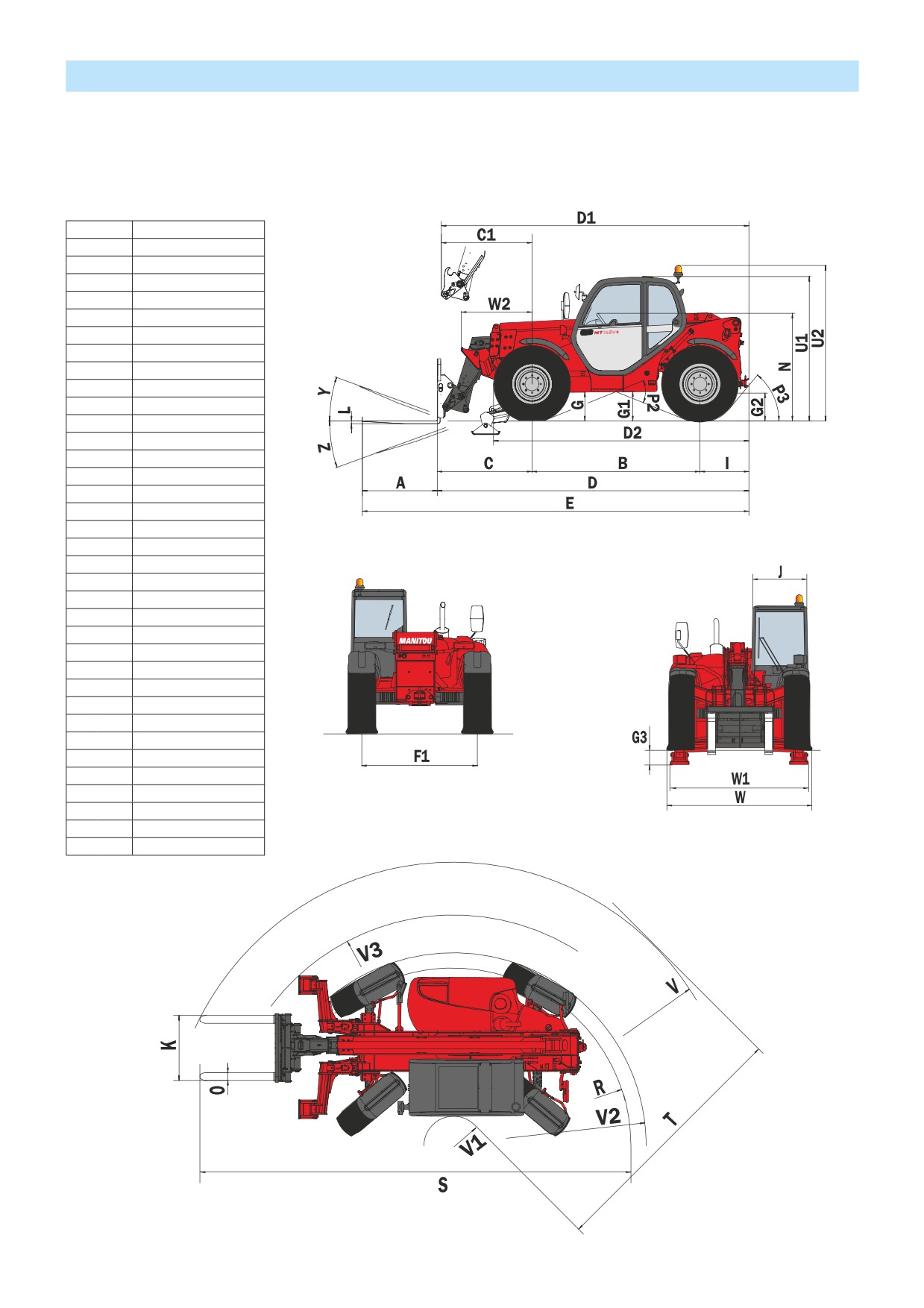
DIMENSIONS AND LOAD CHART
MT 1030 S Série 4-E3
MT 1030 S Turbo Série 4-E3
A
(mm)
1200
B
(mm)
2690
C
(mm)
1513
C1
(mm)
1602
D
(mm)
4992
D1
(mm)
5081
D2
(mm)
4050
E
(mm)
6192
F
(mm)
1846
F1
(mm)
1846
G
(mm)
455
G1
(mm)
440
G2
(mm)
440
G3
(mm)
220
I
(mm)
789
J
(mm)
865
K
(mm)
1040
L
(mm)
45
N
(mm)
1690
O
(mm)
125
P2
(°)
44
P3
(°)
53
R
(mm)
3545
S
(mm)
7810
T
(mm)
3640
U1
(mm)
2300
U2
(mm)
2550
V
(mm)
4950
V1
(mm)
1310
V2
(mm)
3752
V3
(mm)
4200
W
(mm)
2260
W1
(mm)
2210
W2
(mm)
1132
Y
(°)
11,9
Z
(°)
113,7
2-32
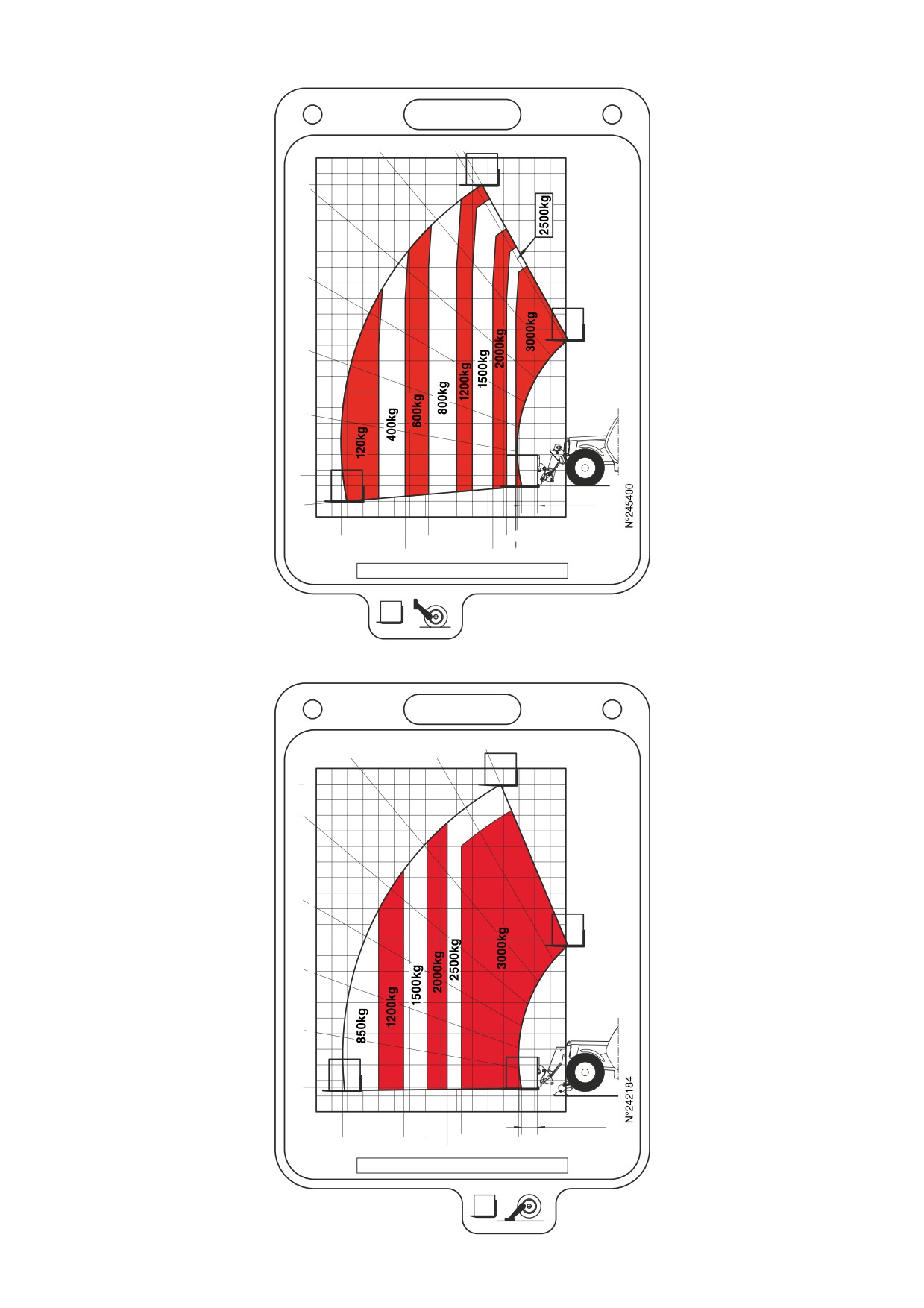
MT1030 S
50°
60° 61°
40°10
9.64
9
8
7
30°
6
5
20°
4
3
10°
2
1
0°
0m
0.5m
-5°
-1
7
6
5
4
3
2
1
0m
1.56
7.2
4.4
1.9
5.15
2.34
1.60
SUIVANT NORME EN 1459 annexe B.
MT1030 S
50°
60°
67.3°
10
9.98
40°
9
8
7
30°
6
5
20°
4
3
10°
2
1
0°
0m
-0.5
7
6
5
4
3
2
1
0m
0.5m
3.35
7.15
5.2
4.45
1.52
3.8
SUIVANT NORME EN 1459 annexe B.
2-33

INSTRUMENTS AND CONTROLS
3
25
24
25
7
4
6
20
19
11
27
21
20
20
8
5
20
25
16
17
26
12
9
15
14
20
1
10
22
2
12
2
18
23
13
38
5
29
36
39
30
28
36
35
34
2-34
DESCRIPTION
1 - DRIVER’S SEAT
2 - SAFETY BELT
3 - CONTROL AND SIGNAL LIGHTS PANEL
4 - LONGITUDINAL STABILITY ALARM
5 - SWITCHES
6 - LIGHT SWITCH, HORN AND INDICATOR SWITCH
7 - FRONT AND REAR WINDSCREEN WIPER SWITCH
8 - IGNITION SWITCH
9 - BRAKING OIL AND WINDSCREEN WASHER TANK ACCESS PANEL
10 - ARMREST
11 - CAR RADIO (OPTION)
12 - FUSES AND RELAYS IN THE CAB
13 - FUSES AND RELAYS UNDER THE ENGINE HOOD
14 - ACCELERATOR PEDAL
15 - SERVICE BRAKE PEDAL AND TRANSMISSION CUT-OFF
16 - GEAR LEVER AND TRANSMISSION CUT-OFF
17 - FORWARD/NEUTRAL/REVERSE GEAR SELECTION
18 - PARKING BRAKE LEVER
19 - STEERING SELECTION
20 - HYDRAULIC CONTROLS AND TRANSMISSION CUT-OFF
21 - FUNCTION FILES
22 - HEATER CONTROL
22 - AIR CONDITIONING CONTROLS (OPTION AIR CONDITIONING)
23 - CAB FILTER VENTILATORS
24 - WINDSCREEN DEMISTER VENTS
25 - HEATING VENTS
26 - DOOR LOCK
27 - LOCKING HANDLE FOR UPPER HALF-DOOR
28 - UNLOCKING BUTTON FOR UPPER HALF DOOR
29 - HANDLE FOR REAR WINDOW OPENING
30 - TOOL BOX AND DOCUMENT HOLDER
31 - FRONT LIGHTS (NOT ILLUSTRATED)
32 - REAR LIGHTS (NOT ILLUSTRATED)
33 - FLASHING LIGHT (NOT ILLUSTRATED)
34 - DOCUMENT HOLDER NET
35 - LEVEL INDICATORS
36 - SUN-SHADE (OPTION)
37 - INSIDE REAR-VIEW MIRROR (OPTION) (NOT SHOWN)
38 - ROOF LIGHT
39 - HOOK
40 - TOOL BOX (OPTION) (NOT SHOWN)
NOTE: All the terms such as: RIGHT, LEFT, FRONT, REAR are meant for an observer seated on driver’s seat and looking in front of
him.
2-35

1 - DRIVER’S SEAT
DESIGNED FOR MAXIMUM COMFORT, THIS SEAT CAN BE ADJUSTED AS FOLLOWS.
LONGITUDINAL ADJUSTMENT
1
- Pull locking lever 1 towards the right.
- Slide the seat to the required position.
- Release the lever and be sure it returns to the lock position.
SEAT SUSPENSION ADJUSTMENT
- Refer to the seat’s graduation.
- Turn handle 2 depending on the driver’s weight.
ADJUSTMENT OF THE ANGLE OF THE BACK-REST
- Pull locking lever 3 upwards.
- Slide the back-rest to the required position.
3
- Release the lever and be sure it returns to the lock position.
2
A
1 - DRIVER’S SEAT (OPTION)
DESIGNED FOR MAXIMUM COMFORT, THIS SEAT CAN BE ADJUSTED AS FOLLOWS.
WEIGHT ADJUSTMENT (FIG. A)
It is advised that the weight be adjusted when the driver is not sitting in the cab.
- Refer to graduation 1 of the seat.
- Turn handle 2 according to the driver’s weight.
2
1
NOTE: To avoid any health problems, it is recommended that the weight should be checked
and adjusted before starting up the lift truck.
SEAT HEIGHT ADJUSTMENT (FIG. B)
Raise the seat to the desired position, until you hear the ratchet click. If you raise the seat
above the last notch (stop), the seat drops down to the lowest position.
B
SEAT BACK-REST ANGLE ADJUSTMENT (FIG. C)
The back-rest angle of the seat may be adjusted to suit the individual.
- Press the left-hand button while pushing on the seat or relaxing pressure on the seat to
find a comfortable position.
C
2-36

SEAT DEPTH ADJUSTMENT (FIG. D)
D
The depth of the seat may be adjusted to suit the individual.
- Press the right-hand button while raising or lowering the seat to find the desired
position.
EXTENDING THE HEAD-REST (FIG. E)
- The height of the back-rest can be adjusted by pulling it upwards (the notches will click)
up to the stop.
- The head-rest can be removed by applying sufficient pressure to pull it off the stop.
LUMBAR ADJUSTMENT (FIG. F)
This increases the comfort of the seat and the driver’s freedom of movement.
- Turn the handle either left or right to adjust the height or depth of the lumbar support.
ADJUSTMENT OF THE ANGLE OF THE BACK-REST (FIG. G)
- Support the back-rest, pull the lever and position the back-rest to find the desired
E
position.
If you do not support the back-rest when making adjustments, it swings completely forwards.
LONGITUDINAL ADJUSTMENT (FIG. H)
- Adjust the locking lever until you reach the position required. This then locks and the seat
will not shift into another position.
MAINTENANCE (FIG. I)
Dirt may adversely affect the correct functioning of the seat. For this reason, make sure
your seat is always clean.
- To clean or change the cushions, simply remove them from the seat frame.
F
A rocking head-rest increases the risk of an accident !
Avoid wetting the cushion fabric when cleaning. Check the resistance of the fabric on a
small hidden area before using any fabric or plastic cleaner.
G
I
H
2-37

1 - BASICPNEUMATICDRIVER’S SEAT (OPTION)
A
DESIGNED FOR MAXIMUM COMFORT, THIS SEAT CAN BE ADJUSTED AS FOLLOWS.
WEIGHT ADJUSTMENT (FIG. A)
It is advised that you adjust the seat according to your weight when sitting.
- Switch on lift truck ignition.
- Push or pull lever 1 until green appears in display 2 indicating correct adjustment according
to your weight.
NOTE: To avoid any health problems, it is recommended that the weight should be checked
and adjusted before starting up the lift truck.
SEAT HEIGHT ADJUSTMENT (FIG. B)
When weight adjustment has been carried out, you can then modify seat height.
- Keep the ignition on in the lift truck.
B
- Push or pull lever 1 until green appears and adjust the height of the seat while checking
that the green in display 2 remains visible.
To avoid causing any damage, do not activate the compressor for over 1 minute.
SEAT BACK-REST ANGLE ADJUSTMENT (FIG. C)
The back-rest angle of the seat may be adjusted to suit the individual.
- Press the left-hand button while pushing on the seat or relaxing pressure on the seat to
find a comfortable position.
SEAT DEPTH ADJUSTMENT (FIG. D)
The depth of the seat may be adjusted to suit the individual.
- Press the right-hand button while raising or lowering the seat to find the desired
position.
C
EXTENDING THE HEAD-REST (FIG. E)
- The height of the back-rest can be adjusted by pulling it upwards (the notches will click)
up to the stop.
- The head-rest can be removed by applying sufficient pressure to pull it off the stop.
D
E
2-38

LUMBAR ADJUSTMENT (FIG. F)
F
This increases the comfort of the seat and the driver’s freedom of movement.
- Turn the handle either left or right to adjust the height or depth of the lumbar support.
ADJUSTMENT OF THE ANGLE OF THE BACK-REST (FIG. G)
- Support the back-rest, pull the lever and position the back-rest to find the desired
position.
If you do not support the back-rest when making adjustments, it swings completely forwards.
HORIZONTAL SHOCK ABSORBER (FIG. H)
In certain conditions (e.g. driving with a trailer) it is advised that a horizontal shock absorber
be used. The driver’s seat is thus better able to absorb jerks in the direction of travel.
- Position 1: Horizontal shock absorber fitted.
G
- Position 2: Horizontal shock absorber removed.
LONGITUDINAL ADJUSTMENT (FIG. I)
- Adjust the locking lever until you reach the position required. This then locks and the seat
will not shift into another position.
SERVICING (FIG. J)
Dirt may adversely affect the correct functioning of the seat. For this reason, make sure
your seat is always clean.
- To clean or change the cushions, simply remove them from the seat frame.
A rocking head-rest increases the risk of an accident !
Avoid wetting the cushion fabric when cleaning. Check the resistance of the fabric on a
H
small hidden area before using any fabric or plastic cleaner.
I
J
2-39

1 - DELUXE PNEUMATICDRIVER’S SEAT (OPTION)
A
DESIGNED FOR MAXIMUM COMFORT, THIS SEAT CAN BE ADJUSTED AS FOLLOWS.
WEIGHT ADJUSTMENT (FIG. A)
It is advised that you adjust the seat according to your weight when sitting.
- Switch on lift truck ignition.
- Pull or push lever 1 briefly. Adjustment is automatic.
NOTE: To avoid any health problems, it is recommended that the weight should be checked
and adjusted before starting up the lift truck.
SEAT HEIGHT ADJUSTMENT (FIG. B)
When weight adjustment has been carried out, you can then modify seat height.
- Keep the ignition on in the lift truck.
B
- Pull or push lever 1 and adjust the seat height.
To avoid causing any damage, do not activate the compressor for over 1 minute.
SEAT BACK-REST ANGLE ADJUSTMENT (FIG. C)
The back-rest angle of the seat may be adjusted to suit the individual.
- Press the left-hand button while pushing on the seat or relaxing pressure on the seat to
find a comfortable position.
SEAT DEPTH ADJUSTMENT (FIG. D)
The depth of the seat may be adjusted to suit the individual.
- Press the right-hand button while raising or lowering the seat to find the desired
C
position.
EXTENDING THE HEAD-REST (FIG. E)
- The height of the back-rest can be adjusted by pulling it upwards (the notches will click)
up to the stop.
- The head-rest can be removed by applying sufficient pressure to pull it off the stop.
LUMBAR ADJUSTMENT (FIG. F)
This increases the comfort of the seat and the driver’s freedom of movement.
- Press the raise and lower switches to adjust the cur vature of the seat back to your
requirements.
D
E
F
2-40

ADJUSTMENT OF THE ANGLE OF THE BACK-REST (FIG. G)
G
- Support the back-rest, pull the lever and position the back-rest to find the desired position.
If you do not support the back-rest when making adjustments, it swings completely forwards.
HORIZONTAL SHOCK ABSORBER (FIG. H)
In certain conditions (e.g. driving with a trailer) it is advised that a horizontal shock absorber
be used. The driver’s seat is thus better able to absorb jerks in the direction of travel.
- Position 1: Horizontal shock absorber fitted.
- Position 2: Horizontal shock absorber removed.
DAMPING (FIG. I)
The damping of the seat can be adjusted to suit the nature of the terrain. The comfort of
the seat is thus adjustable to suit your requirements.
H
- Position 1: Soft damping.
- Position 2: Hard damping.
LONGITUDINAL ADJUSTMENT (FIG. J)
- Adjust the locking lever until you reach the position required. This then locks and the seat
will not shift into another position.
MAINTENANCE (FIG. K)
Dirt may adversely affect the correct functioning of the seat. For this reason, make sure
your seat is always clean.
- To clean or change the cushions, simply remove them from the seat frame.
A rocking head-rest increases the risk of an accident!
Avoid wetting the cushion fabric when cleaning. Check the resistance of the fabric on a
I
small hidden area before using any fabric or plastic cleaner.
J
K
2 - SAFETY BELT
- Sit correctly on the seat.
- Check that seat belt is not twisted.
- Place the seat belt at hip level.
- Attach the seat belt and check that it locks.
- Adjust the seat belt to your body shape without squeezing your hip and without over-slack.
In no event should the lift truck be used if the seat belt is defective (fixing, locking, cuts, tears, etc.). Repair or replace the seat belt immediately.
2-41

3 - CONTROL ANDSIGNAL LIGHTS PANEL
B
C1
A1 A2 A3 A4
C
D
A
HOURS
12
9
3
6
CONTROL INSTRUMENTS
A - I.C. ENGINE WATER TEMPERATURE
Temperature zone:
A1 - Blue zone (0° - 50°) Use the lift truck with moderation, wait for temperature to increase before normal operation.
A2 - Green zone (50° - 100°) Use lift truck normally.
A3 - White/red zone (100° - 105°) Use lift truck with moderation, monitor the temperature.
A4 - Red zone (105° - 120°) Stop the lift truck, look for the cause of overheating.
NOTE: Red indicator light
comes on between zone A3 and A4.
B - HOUR METER
C - FUEL LEVEL
Red zone C1 indicates that you are using the reser ve supply and that time of use is limited.
D - CLOCK
SIGNAL LIGHTS
A permanently lit or flashing warning lamp, with the engine running, is the sign of an operating fault. The lighting of some lamps may be accompanied
by an audible signal. Do not ignore this warning, consult your dealer without delay.
If one of the warning lamps comes on while the lift truck is in motion, stop the lift truck under the safest possible conditions.
When activating the electrical system of the lift truck, all the red lamps and the panel’s buzzer must light to indicate their good
working order. If one of the red lamps or the buzzer does not function, carr y out the necessar y repairs.
NOT USED
NOT USED
NOT USED
STOP
NOT USED
2-42
RED GEAR BOX OIL PRESSURE WARNING INDICATOR LIGHT
The lamp and buzzer come on when there is an abnormal drop in gear box pressure, in for ward gear. Stop the I.C engine
and look for the cause (gear box oil level, possible leak, radiator, etc.).
NOTE: The signal light operates in for ward travel conditions only, the signal should not be taken into account when the I.C.
engine is running at idle or is stopped.
RED TRANSMISSION OIL TEMPERATURE FAULT INDICATOR LIGHT
The lamp and buzzer come on when the gearbox oil temperature is abnormally high. Stop the I.C engine and look for the
cause (gear box oil level, possible leak, radiator, etc.).
RED BRAKING OIL LEVEL WARNING INDICATOR LIGHT
If the lamp and the buzzer come on, when the lift truck is running, stop the I.C. engine immediately and look for the cause
(braking oil level, possible leak, etc.). In the event of an abnormal dropping of the level, consult your dealer.
RED PARKING BRAKE LAMP
This lamp comes on when the parking brake is applied.
RED BATTERY CHARGE WARNING INDICATOR LIGHT
If the lamp and the buzzer come on when the lift truck is running, stop the I.C. engine immediately and look for the cause
(electric circuit, alternator belt, alternator, etc.).
RED I.C. ENGINE OIL PRESSURE WARNING INDICATOR LIGHT
If the lamp and the buzzer come on when the lift truck is running, stop the I.C. engine immediately and look for the cause
(engine oil level, possible leak, etc.).
RED I.C. ENGINE WATER TEMPERATURE WARNING INDICATOR LIGHT
If the lamp and the buzzer come on when the lift truck is running, stop the I.C. engine immediately and look for the cause
(coolant level, possible leak, radiator, etc.).
RED AIR FILTER OR HYDRAULIC RETURN FILTER CLOGGED INDICATOR LIGHT
The lamp and buzzer come on when the air filter cartridge or the hydraulic return oil filter cartridge is clogged up. Stop the
I.C. engine and carr y out the necessar y repairs (see cleaning and replacement requirements in chapter: 3 - MAINTENANCE:
FILTERS CARTRIDGES AND BELTS).
GREEN DIRECTION INDICATOR LAMP
GREEN SIDELIGHTS LAMP
GREEN LOW BEAM LAMP
BLUE MAIN BEAM LAMP
2-43

4 - LONGITUDINAL STABILITY ALARM
This device warns the operator that the lift truck is approaching the limit of longitudinal stability. However, lateral stability can
reduce the load chart in the upper part, and this reduction is not detected by the longitudinal stability alarm.
NOTE: Since Januar y 2010, Simple movement cut-off is fitted as standard (See: 2 - DESCRIPTION: DESCRIPTION AND USE OF THE
OPTIONS).
The operator must respect the lift truck’s load chart.
OPERATION
When the lift truck is switched on a control test is automatically carried out.
- Correct operation: All leds and the sound alarm function continuously for 2 seconds.
- Faulty operation: All leds and the sound alarm function intermittently (stop the lift truck and consult your dealer, never attempt
a repair yourself).
A - VISUAL ALARM
A1 - 4 green leds: There is a large reser ve of longitudinal stability.
A2 - 2 yellow leds: The lift truck is approaching the limit of longitudinal stability,
A
move carefully.
A4
A3 - 1 red led: The lift truck is ver y near at the limit of longitudinal stability. The alarm
C
A3
sounds simultaneously with a slow intermittent sound. Move ver y
A2
B1
carefully.
A2
A4 - 1 red led: The lift truck is at the authorized limit of longitudinal stability. The alarm
B
A1
sounds simultaneously with a speed intermittent sound. Only make
A1
de-aggravating hydraulic movements in the following order; retract
A1
and raise the boom.
A1
B - SOUND ALARM
Used to switch off the sound alarm when using the lift truck with loading and earth moving
buckets. When it is switched off, the red led B1 indicates that the sound alarm has been
cut off and only the visual alarm is working. Under other operating conditions, the sound alarm must be switched on.
C - TEST SWITCH
Press the switch to verify at any time that the longitudinal stability alarm is working.
NOTE: This test does not verify that the alarm is correctly set; this must be checked at ever y periodic ser vice.
- Correct operation: All leds and the sound alarm function continuously.
- Faulty operation: All leds and the sound alarm function intermittently (stop the lift truck and consult your dealer, never attempt
a repair yourself).
D - STRAIN GAUGE
Disassembly or adjustment of the strain gauge is prohibited, this must only be done by specially trained
personnel, consult your dealer.
D
5 - SWITCHES
NOTE: The location of the switches may var y depending on the options.
A - OPTION
MT 732 Série D-E3
D
A B C
MT 932 Série D-E3
MT 1030 S Série 4-E3
MT 1030 S Turbo Série 4-E3
- OPTION Electrical boom provision (See: 2 - DESCRIPTION: DESCRIPTION AND
USE OF THE OPTIONS).
2
B - OPTION
1
E
F
G H
2-44

C - WHEEL ALIGNMENT LAMPS
D - WARNING LIGHTS
E - REAR FOG LIGHT
F - OPTION
MT 732 Série D-E3
MT 932 Série D-E3
MT 1030 S Série 4-E3
MT 1030 S Turbo Série 4-E3
- OPTION Self-cleaning fan (See: 2 - DESCRIPTION: DESCRIPTION AND USE OF THE OPTIONS).
G - STEERING SELECTION
H - TRANSMISSION CUT-OFF
The switch selects transmission cut-off to the ser vice brake pedal or the hydraulic controls lever.
Position 1: Indicator light on, transmission cut-off to ser vice brake pedal effected.
Position 2: Indicator light off, transmission cut-off to hydraulic control lever effected.
USE OF TRANSMISSION CUT-OFF
Transmission cut-off to brake pedal (position 1).
• When loading.
Transmission cut-off to hydraulic controls lever (position 2).
• When driving.
• For inching and continuous stopping and starting (delicate handling). In order to optimise hydraulic movements, cut off
transmission to the hydraulic controls lever.
• Starting up on a slope.
NOTE: In all cases transmission cut-off can be effected using the gear lever.
I - REVOLVING LIGHT
J - OPTION FRONT AND REAR WORKING LIGHTS
K - OPTION
I
J
K
L
M
MT 732 Série D-E3
MT 932 Série D-E3
MT 1030 S Série 4-E3
MT 1030 S Turbo Série 4-E3
- OPTION Boom head light.
L - REAR WINDOW DEFROSTING OPTION
M - SIDE WINDSCREEN WIPER + ROOF WINDSCREEN WIPER OPTION
N - OPTION
O - OPTION
P - OPTION
MT 732 Série D-E3
N
O
P
Q
MT 932 Série D-E3
MT 1030 S Série 4-E3
MT 1030 S Turbo Série 4-E3
- OPTION Attachment hydraulic locking device (See: 2 - DESCRIPTION: DESCRIPTION
AND USE OF THE OPTIONS).
Q - OPTION
2-45
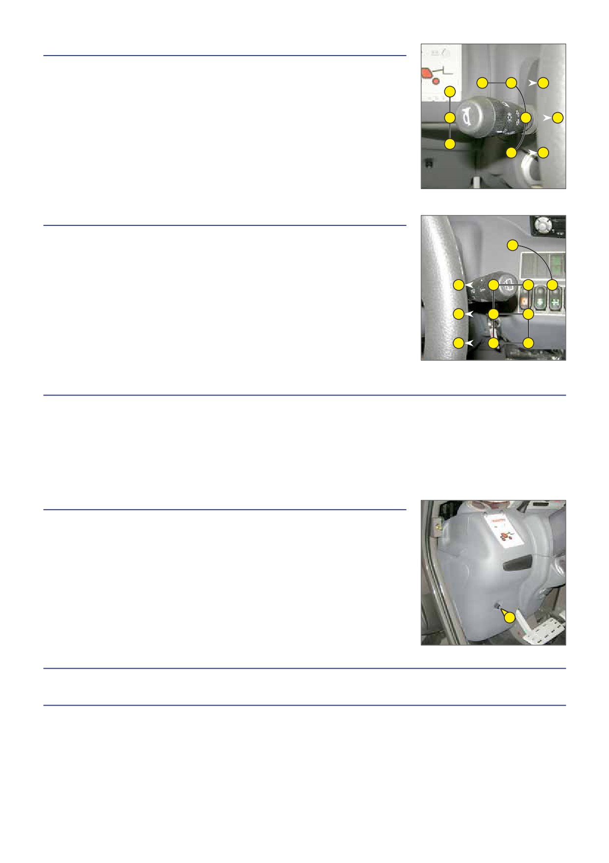
6 - LIGHT SWITCH, HORNANDINDICATORSWITCH
The switch controls the visual and sound alarms.
A - All lights are off, the direction indicators do not flash.
F
E
G
B
B - The right hand direction indicators flash.
C - The left hand direction indicators flash.
D - The sidelights and the rear lights are on.
A
D
G
E - The dipped headlights and the rear lights are on.
F - The main beam headlights and the rear lights are on.
C
G - Headlight signal.
A
G
Pressing the switch sounds the horn.
NOTE: The positions D - E - F - G can be carried out without the ignition being on.
7 - FRONT ANDREARWINDSCREENWIPERSWITCH
FRONT WINDSCREEN WIPER
E
A - Front windscreen wiper off.
B - Front windscreen wiper low speed setting.
C - Front windscreen wiper high speed setting.
D - Front windscreen wiper intermittent setting.
D
A
A
F
REAR WINDSCREEN WIPER
D
B
B
E - Rear windscreen wiper off.
F - Rear windscreen wiper on.
D
C
C
NOTE: These functions will only work when the ignition is switched on.
8 - IGNITIONSWITCH
The key switch has five positions:
P - Ignition off, parking position.
O - Ignition switched off and I.C. engine stopped.
I - Ignition on.
II - Heating.
III - The I.C. engine starts, return to position I as soon as the key is released.
9 - BRAKINGOIL ANDWINDSCREENWASHERTANK ACCESS PANEL
- Loosen screw 1 and lift up the braking oil and windscreen washer tank access panel.
(See: 3 - MAINTENANCE: B - EVERY 50 HOURS SERVICE.)
1
10 - ARMREST
11 - CAR RADIO (OPTION)
2-46

12 - FUSES AND RELAYS IN THE CAB
- Lift up the fuse and relay access panel 1.
1
NOTE: A sticker on the inside of the access panel gives a clear display of the use of the
components described below.
Always replace a faulty fuse with another of equivalent rating. Never use a fuse that has been repaired.
F1 - Security stabilizers (7,5A). (E F)
- OPTION. (A B C D)
F2 - OPTION Working tail light (10A).
F3 - Rear windscreen wiper (7,5A).
- OPTION Roof windscreen wiper (7.5A).
- OPTION Side windshield wiper (7,5A).
A: MT 728 Série D-E3
F4 - Stop I.C. engine electrovalve (7,5A).
B: MT 732 Série D-E3
- OPTION.
C: MT 928 Série D-E3
F5 - Revolving light (7,5A).
D: MT 932 Série D-E3
F6 - Wheel alignment (5A).
E: MT 1030 S Série 4-E3
F7 - Longitudinal stability alarm (10A).
F: MT 1030 S Turbo Série 4-E3
- Cutting-off “simple” hydraulic movements (10A). (A C)
F32
F31
- OPTION Cutting-off “simple” hydraulic movements. (10A). (B D E F)
DIST.
LSU
- OPTION Cutting off “aggravating” hydraulic movements (10A).
3A
20A
K0
K1
F8 - For ward/neutral/reverse selector (15A).
O
PT.
OPT.
- Transmission cut-off (15A).
- Reverse buzzer alarm (15A).
K2
K3
K4
- Reverse lights (15A).
F9 - Control panel (5A).
F10 - Sound alarm (15A).
K5
K6
- Stop switch (15A).
OPT.
F11 - OPTION Boom head light (10A). (B D E F)
- OPTION Blue front and rear working lights (10A). (B D)
K7
K8
K9
- OPTION. (A C)
OPT.
F12 - Indicators (10A).
F13 - Heating (30A).
F1
F2
F3
F4
F5
F6
F7
F8
F9
F10
F11
F12
F13
F14
F15
OPT.
OPT.
OPT.
OPT.
OPT.
F14 - OPTION.
OPT.
OPT.
10A max.
15A
10 A
10A
7.5A
5A
10A
15A
5A
15A
15A max.
10A
30A
25A max.
25A max.
F15 - OPTION.
F16
F17
F18
F19
F20
F21
F22
F23
F24
F25
F26
F27
F28
F29
F30
F16 - OPTION Air conditioning (7,5A).
OPT.
O
PT.
O
PT.
O
PT.
OPT.
F17 - OPTION Electrovalve on boom head (10A). (B D E F)
OPT.
10A max.
15A max.
15A
15A max.
10A max.
10A
15A max.
7.5A
7.5A
7.5A
7.5A
15A
15A
15A
25A
- OPTION Electrovalve on boom head + attachment hydraulic locking
device (10A). (B D E F)
- OPTION Electrical boom provision (10A). (B D E F)
- OPTION Anti-theft device provision (10A).
- OPTION Anti-theft system (10A).
- OPTION Anti-start system (10A).
- OPTION Self-cleaning fan (10A). (B D E F)
- OPTION Electrovalve on boom head + self-cleaning fan (15A). (B D E F)
F18 - OPTION Front working head light (15A).
F19 - OPTION Rear window defrosting (15A).
F20 - OPTION Pneumatic seat (10A).
F21 - Front windscreen wiper and windscreen washer (10A).
F22 - OPTION.
F23 - Right sidelight (7,5A).
- Sidelight indicator light (7,5A).
- Control panel lighting (7,5A).
- OPTION Number plate lighting (7,5A). (B D E F)
F24 - Left sidelights (7,5A).
F25 - Right indicators (7,5A).
F26 - Left indicators (7,5A).
F27 - Low beam (15A).
- Low beam indicator light (15A).
- Rear fog light (15A).
F28 - Main beam (15A).
- Main beam lamp (15A).
F29 - Warning lights (15A).
- Roof light (15A).
- OPTIONAL (+)permanent (15A).
F30 - Lights, horn and indicator switch (25A).
F31 - Starter (25A).
2-47

K0 - OPTION Air conditioning.
A: MT 728 Série D-E3
K1 - OPTION.
B: MT 732 Série D-E3
K2 - Transmission cut-off relay.
C: MT 928 Série D-E3
K3 - Reverse gear relay.
D: MT 932 Série D-E3
K4 - For ward gear relay.
E: MT 1030 S Série 4-E3
K5 - Buzzer.
F: MT 1030 S Turbo Série 4-E3
K6 - OPTION Electrovalve on boom head. (B D E F)
- OPTION Electrical boom provision. (B D E F)
F32
F31
DIST.
- OPTION Electrovalve on boom head + attachment hydraulic locking
LSU
3A
20A
K0
K1
device. (B D E F)
- OPTION. (A C)
O
PT.
OPT.
K7 - Cutting off “simple” hydraulic movements. (A C)
K2
K3
K4
- OPTION Cutting off “simple” hydraulic movements. (B D E F)
- OPTIONAL Cutting off “aggravating” hydraulic movements.
K8 - Safety system starting switch relay.
K5
K6
K9 - Flashing unit.
OPT.
K7
K8
K9
OPT.
F1
F2
F3
F4
F5
F6
F7
F8
F9
F10
F11
F12
F13
F14
F15
OPT.
OPT.
OPT.
OPT.
OPT.
OPT.
OPT.
10A max.
15A
10 A
10A
7.5A
5A
10A
15A
5A
15A
15A max.
10A
30A
25A max.
25A max.
F16
F17
F18
F19
F20
F21
F22
F23
F24
F25
F26
F27
F28
F29
F30
OPT.
O
PT.
OPT.
O
PT.
O
PT.
OPT.
10A max.
15A max.
15A
15A max.
10A max.
10A
15A max.
7.5A
7.5A
7.5A
7.5A
15A
15A
15A
25A
13 - FUSES AND RELAYS UNDER THE ENGINE HOOD
Remove casing 1 and cover 2 for access to fuses and relays.
Always replace a faulty fuse with another of equivalent rating. Never use a fuse that has been repaired.
2
F40 - Lift truck electrical equipment (40A).
F41 - Lift truck electrical equipment (40A).
F42 - Preheating I.C. engine (80A).
F43 - Alternator (80A).
F45 - OPTION Diesel decongealant (15A). (B D E F)
1
K16 - Engine preheating relay.
K20 - OPTION Diesel decongealant. (B D E F)
K16
F40
F42
F43
F41
2-48

14 - ACCELERATOR PEDAL
15 - SERVICE BRAKE PEDAL AND TRANSMISSION CUT-OFF
MT 728 Série D-E3
MT 928 Série D-E3
The pedal applies on the front and rear wheels by an hydraulic brake system, and allows the lift truck to be slowed down and
stopped. Depending on the position of the transmission cut-off switch, it enables the free travel to cut off transmission (see:
2 - DESCRIPTION: 5 - SWITCH PANEL).
MT 732 Série D-E3
MT 932 Série D-E3
MT 1030 S Série 4-E3
MT 1030 S Turbo Série 4-E3
The pedal applies on the front and rear wheels by an hydraulic brake system, and allows the lift truck to be slowed down and
stopped. Depending on the position of the transmission cut-off switch, it enables the free travel to cut off transmission (see:
2 - DESCRIPTION: 5 - SWITCH PANEL).
16 - GEAR LEVER AND TRANSMISSION CUT-OFF
In order to change speeds, it is necessary to cut the transmission by pressing the button
1 on the lever.
4
2
1st gear: To the right, backwards.
1
2nd gear: To the right, for wards.
3rd gear: To the left, backwards.
4th gear: To the left, for wards.
USING THE GEARS ON THE GEAR BOX
3
1
- On these lift trucks with a torque converter, it is not necessar y to automatically start up
in 1st speed and progress up the gears.
The choice of transmission gear ratio should be made carefully according to the nature of the work being
carried out. A poor choice may result in the extremely rapid rise of the transmission oil temperature
through excessive slipping of the converter, which could lead to serious damage to the transmission
(it is essential to stop and change the working conditions if the transmission oil temperature indicator light comes on). This poor choice may also result
in a reduction in the lift truck’s performance in forward gear. When the forward force increases, the forward speed in the r gear (for example, in 3rd gear)
may be lower than the forward speed that could be obtained with the r-1 gear (in 2nd instead of 3rd).
In general, we would advise you to use the following gears according to the nature of the work being carried out.
• On the road: Set off in 3rd gear and go up to 4th if the conditions and state of the road permit it. In hilly areas, set off in 2nd
gear and go up to 3rd if the conditions and state of the road permit it.
• With a trailer on the road: Set off in 2nd gear and switch to 3rd if the conditions and state of the road permit it.
• Handling: 3rd gear.
2nd gear in restricted spaces.
• Loading (reclaiming with bucket, manure fork, etc.): 2nd gear.
• Earth moving: 1st gear.
2-49
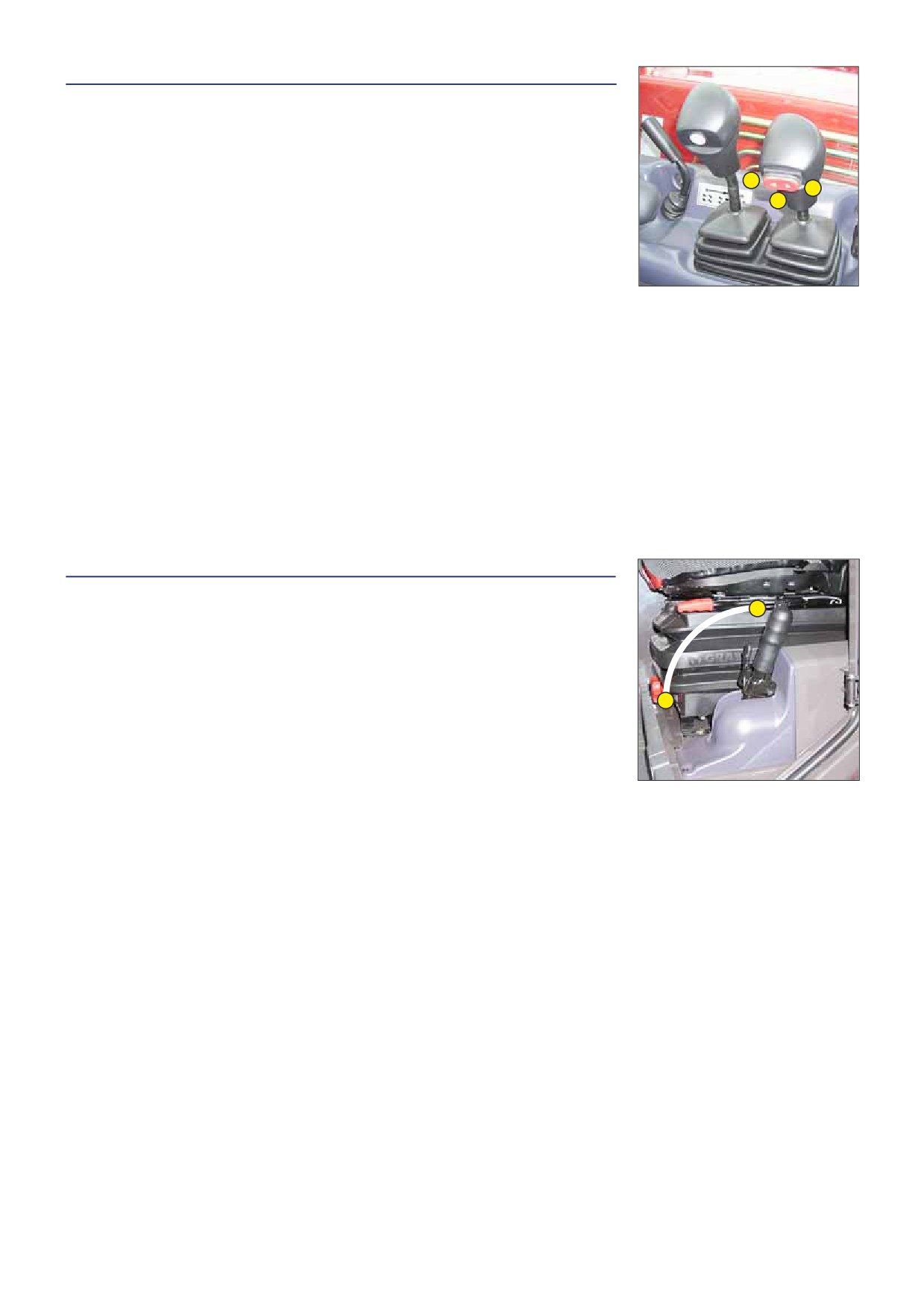
17 - FORWARD/NEUTRAL/REVERSE GEAR SELECTION
FORWARD: Push the knob for ward (position A).
REVERSE: Pull the knob backwards (position B).
NEUTRAL: The knob must be in the intermediate position to start the lift truck (position C).
When operating this control, the lift truck should be travelling at slow speed and not
A
B
accelerating.
C
NOTE: The reverse lights and an acoustic reversing alarm indicate that the lift truck is
running in reverse.
SAFETY FOR MOVING THE LIFT TRUCK
Authorisation to move the lift truck is controlled by an electronic unit. The operator must
obser ve the following sequence to move the truck for wards or backwards:
1 - sit down correctly in the driver’s seat,
2 - release the parking brake,
3 - engage for ward or reverse movement.
To stop the lift truck, he must obser ve the following sequence:
1 - Set the for ward/reverse selector to neutral,
2 - engage the parking brake,
3 - get out of the lift truck.
NOTE: If the operator leaves the driving cab with for ward or reverse engaged, a continuous alarm will sound. While this alarm
sounds, the operator can simply sit back in the seat and continue advancing or reversing.
If the alarm becomes discontinuous, the operator must sit back in the seat, put the for ward/reverse selector back in
neutral and select for ward or reverse if he wishes to continue moving.
18 - PARKING BRAKE LEVER
To prevent accidental loosening or release, the lever is fitted with safety locking.
A
- To apply the parking brake, pull the lever backwards (position A).
- To loosen the parking brake, release and push the lever for wards (position B).
B
2-50

19 - STEERING SELECTION
A
Before selecting one of the three possible steering positions, bring the 4 wheels into
alignment, i.e., in the straight ahead position.
A1
A2
A - GREEN WHEEL ALIGNMENT LAMPS
These lamps come on to indicate the alignment of the wheels in relation to the lift truck.
C
Lamp A1 for the front wheels and lamp A2 for the rear wheels.
Before selecting one of the three possible steering positions, bring all 4 wheels into alignment with
regards to the lift truck axle. Never change the steering mode whilst driving.
B - STEERING SELECTION LEVER
B1 - Front drive wheels (highway traffic).
B2 - Front and rear drive wheels in opposite direction (short steering lock).
B3
B3 - Front and rear drive wheels in the same direction (crab steering).
B
C - SWITCH FOR ALIGNMENT OF THE WHEELS
B1
This switch enables the use or not of the device for alignment of the wheels. The indicator
light indicates its use.
B2
CONTROL FOR ALIGNMENT OF THE WHEELS
- Connect the switch (signal light ON).
- Shift the steering selection lever B into position B2 (short steering lock).
- Turn the steering wheel and bring the rear wheels into alignment until lamp A2 lights up.
- Shift the steering selection lever B into position B1 (highway traffic).
- Turn the steering wheel and bring the front wheels into alignment until lamp A1 lights
up.
Before driving on roads, it is necessary to check the alignment of the rear wheels and to drive in front wheel steer. The control of the alignment of the
rear wheels must be regularly done with the help of the green lamps, while driving the lift truck. In case of anomalies, consult your dealer.
20 - HYDRAULIC CONTROLS AND TRANSMISSION CUT-OFF
Do not attempt to alter the hydraulic system pressure by interfering with the pressure regulating valve. In the event of suspected malfunction, contact
your dealer. ANY ALTERATION MAY RENDER THE WARRANTY NULL AND VOID.
Use the hydraulic controls carefully without jerking, to avoid accidents caused by shaking the lift truck.
MT 728 Série D-E3
MT 928 Série D-E3
A
A - Lifting and telescoping control lever.
B
B - Lifting and tilting control lever.
C - Transmission cut-off button.
C
D - For ward/neutral/reverse selector control button.
D
LIFTING THE LOAD
- Move lever A or B backwards to lift.
- Move lever A or B for wards to lower.
TELESCOPING
- Move lever A to the right to extend.
- Move lever A to the left to retract.
NOTE: Only for MT 928 Série D-E3
When completely retracting the telescopes, insistently operate the control so as to
allow all the telescopes to retract fully.
TILT OF CARRIAGE
- Move lever B to the left to excavate.
- Move lever B to the right to tip.
TRANSMISSION CUT-OFF
- Button C (see: 2 - DESCRIPTION: 5 - SWITCHES).
FORWARD/REVERSE SELECTOR
- Switch D (see 2 - DESCRIPTION: 17 - FORWARD/NEUTRAL/REVERSE GEAR SELECTOR).
2-51

MT 732 Série D-E3
MT 932 Série D-E3
A
A - Lifting and telescoping control lever.
B
B - Lifting and tilting control lever.
C - Attachment cut-off control lever.
D
D - Transmission cut-off control button.
E - For ward/neutral/reverse selector control button.
E
C
LIFTING THE LOAD
- Move lever A or B backwards to lift.
- Move lever A or B for wards to lower.
TELESCOPING
- Move lever A to the right to extend.
- Move lever A to the left to retract.
NOTE: Only for MT 932 Série D-E3
When completely retracting the telescopes, insistently operate the control so as to allow all
the telescopes to retract fully.
TILT OF CARRIAGE
- Move lever B to the left to excavate.
- Move lever B to the right to tip.
ATTACHMENT
- Raise lever C and turn to the left or right.
TRANSMISSION CUT-OFF
- Switch D (see: 2 - DESCRIPTION: 5 - SWITCHES).
FORWARD/REVERSE SELECTOR
- Switch E (see 2 - DESCRIPTION: 17 - FORWARD/NEUTRAL/REVERSE GEAR SELECTOR).
MT 1030 S Série 4-E3
A
MT 1030 S Turbo Série 4-E3
D
B
A - Lifting and telescoping control lever.
B - Lifting and tilting control lever.
C
E - Attachment cut-off control lever.
F
F - Transmission cut-off control button.
G - For ward/neutral/reverse selector control button.
G
E
LIFTING THE LOAD
- Move lever A or B backwards to lift.
- Move lever A or B for wards to lower.
TELESCOPING
- Move lever A to the right to extend.
- Move lever A to the left to retract.
NOTE: When completely retracting the telescopes, insistently operate the control so as to
allow all the telescopes to retract fully.
TILT OF CARRIAGE
- Move lever B to the left to excavate.
- Move lever B to the right to tip.
L.H. STABILIZER
- Move lever C for wards to lower.
- Move lever C backwards to lift.
NOTE: The stabilizers can only be raised after the boom has been retracted.
R.H. STABILIZER
- The lever D for wards when lowering.
- The lever D backwards when lifting.
NOTE: The stabilizers can only be raised after the boom has been retracted.
ATTACHMENT
- Raise lever E and turn to the left or right.
TRANSMISSION CUT-OFF
- Button F (see: 2 - DESCRIPTION: 5 - SWITCH PANEL).
FORWARD/REVERSE SELECTOR
- Switch G (see 2 - DESCRIPTION: 17 - FORWARD/NEUTRAL/REVERSE GEAR SELECTOR).
21 - FUNCTION FILES
These files contain the description of the hydraulic controls and the load charts for the attachments used on the lift truck.
2-52

22 - HEATER CONTROL
A
B
A - HEATING FAN CONTROL
This 3-speed control regulates warm or cold air through the heating ventilators.
B1
B2
B - HEATING TEMPERATURE CONTROL
Allows the temperature inside the cab to be adjusted.
B1 - With the valve closed, the fan delivers fresh air.
B2 - With the valve opened completely, the fan delivers warm air.
The intermediate positions allow the temperature to be adjusted.
22 - AIR CONDITIONING CONTROLS (OPTION AIR CONDITIONING)
A
C
B
The air conditioning only comes on when the forklift truck has been started up. When using your air
conditioning, you must work with the doors and windows closed.
In winter: So as to ensure correct operation and complete efficiency of the air conditioning unit,
start up the compressor once a week, if only for a short spell, so as to lubricate the internal seals.
In cold weather: Warm the I.C. engine before switching on the compressor, so as to allow the
coolant that has collected in the liquid state at the lowest point of the compressor circuit to turn into
gas under the effect of the heat given off by the I.C. engine, as the compressor is liable to be damaged by coolant in the liquid state.
If your air conditioning does not seem to be working properly, have it examined by your dealer (see: 3 - MAINTENANCE: F - EVERY 2000 HOURS OF
SERVICE). Never try to repair any possible problems by yourself.
DESCRIPTION OF THE AIR CONDITIONING CONTROLS
A - Air conditioning system ON/OFF control switch with indicator lamp. Only works when control switch “C” set to 1, 2 or 3.
B - Air temperature control.
C - Air flow and fan speed control. When this control is set to “0” the air conditioning system will not work.
NOTE: Possible losses of water under the lift truck are due to condensate discharges caused by the dr ying effect of the
installation, especially with high outside temperatures and high relative humidity.
For the air conditioning to per form properly, the air intakes must not be blocked by frost, snow or leaves.
When the facility is running, at least one of the cab air grilles must be open so as to avoid any risk of freezing to the
evaporator.
HEATING MODE
The controls must be adjusted in the following way:
A - Control with signal light off.
B - At the required temperature.
C - To the desired position 1, 2 or 3.
CONDITIONED AIR MODE
The controls must be adjusted in the following way:
A - Control with signal light on.
B - At the required temperature.
C - To the desired position 1, 2 or 3.
DEMISTING MODE
The controls must be adjusted in the following way:
A - Control with signal light on.
B - At the required temperature.
C - To the desired position 1, 2 or 3.
NOTE: Direct the ventilators onto the cab’s windows for increased efficiency.
2-53
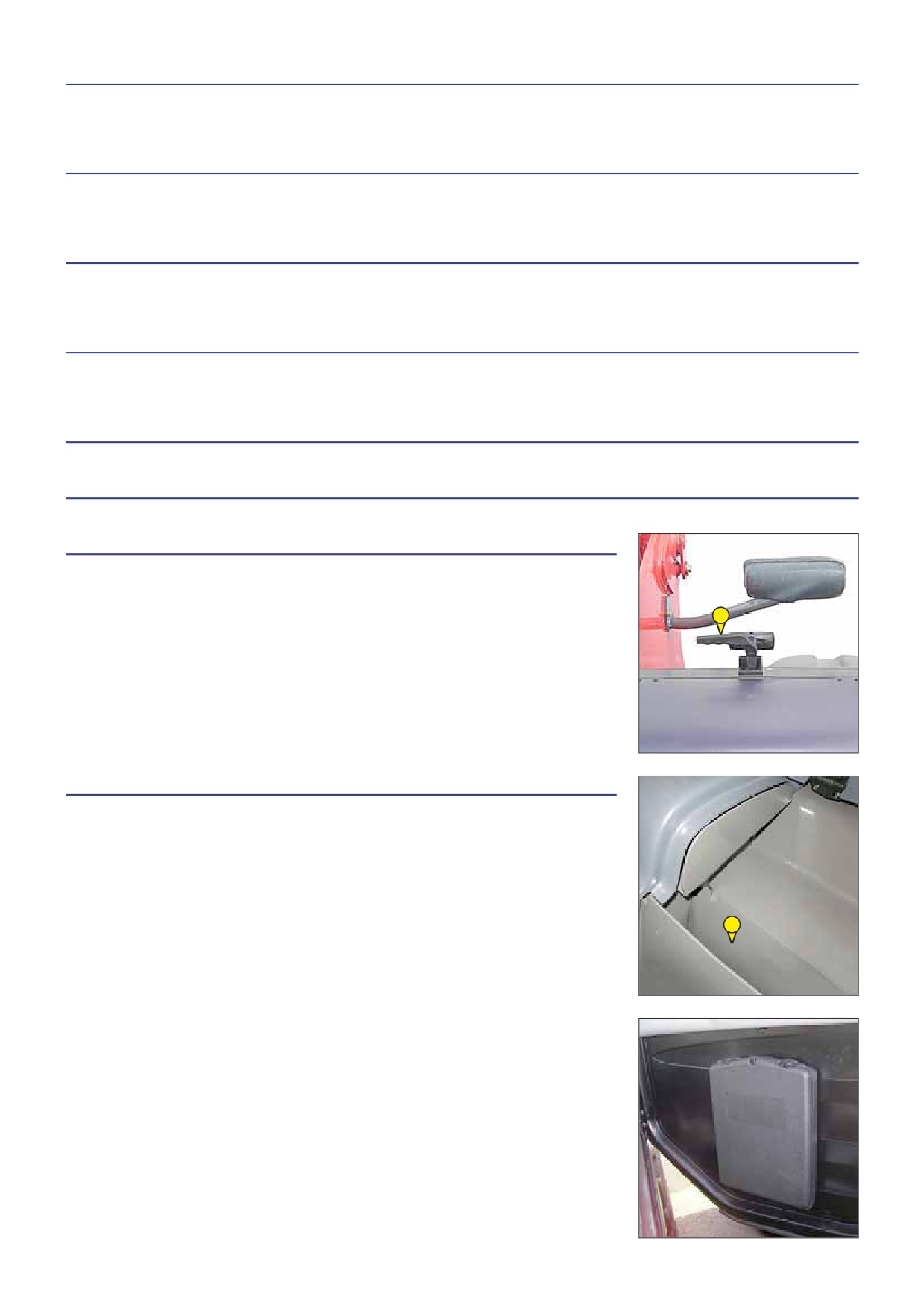
23 - CAB FILTER VENTILATORS
See: 3 - MAINTENANCE: D - EVERY 500 HOURS SERVICE.
24 - WINDSCREEN DEMISTER VENTS
For optimum effectiveness, close the heating ventilators.
25 - HEATING VENTS
These heating vents enable the air to be directed to the interior of the cabin and onto the side windows.
26 - DOOR LOCK
Two keys are provided with the lift truck to enable the cabin to be locked.
27 - LOCKING HANDLE FOR UPPER HALF-DOOR
28 - UNLOCKING BUTTON FOR UPPER HALF DOOR
29 - HANDLE FOR REAR WINDOW OPENING
EMERGENCY EXIT
Use the rear window as an emergency exit, if it is impossible to leave the cab by the door.
29
NOTE: There is an OPTIONAL rear window stay.
30 - DOCUMENT HOLDER
Ensure that the operator’s manual is in its place in the document holder.
30
NOTE: An OPTION waterproof document-holder exists.
2-54

31 - FRONT LIGHTS
A - Left front indicator.
B - Left front dipped headlight.
F
B
C - Left front main beam.
D - Left front sidelight.
A
E - Right front indicator.
E
H
D
F - Right front dipped headlight.
G - Right front main beam.
G
C
H - Right front sidelight.
32 - REAR LIGHTS
A - Left rear indicator.
B - Left rear stoplight.
C - Left tail light.
A
B
C
D
E
F
G
H
I
H
D - Left rear reverse light.
E - Left rear fog light.
F - Right rear fog light.
G - Right rear reverse light.
H - Right tail light.
I - Right rear stoplight.
J - Right rear indicator.
33 - REVOLVING LIGHT
The magnetic revolving light must be clearly visible on the roof of the cab and plugged-in
to socket 1.
1
34 - DOCUMENT HOLDER NET
35 - SPIRIT LEVEL
Enables the operator to check that the lift truck is in the horizontal position.
36
36 - SUN VISOR
35
36
37 - INSIDE REAR-VIEW MIRROR
2-55

38 - ROOF LIGHT
39 - HOOK
38
39
40 - TOOL BOX (OPTION)
MT 732 Série D-E3
MT 932 Série D-E3
MT 1030 S Série 4-E3
MT 1030 S Turbo Série 4-E3
40
2-56
2-57
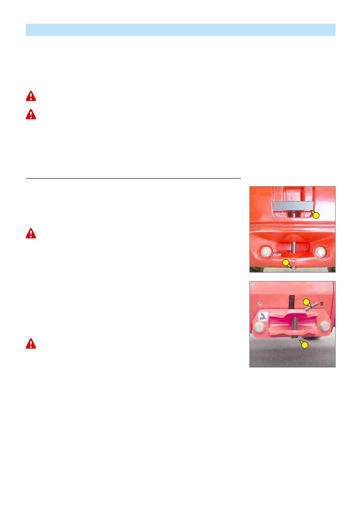
TOWING PIN AND HOOK
Located at the rear of the lift truck, this device is used to attach a trailer. Its capacity is limited for each lift truck by the
authorised gross vehicle weight, tractive effort and maximum vertical force on the coupling point. This information is given on the
manufacturer’s plate fixed to each lift truck (see: 2 - DESCRIPTION: IDENTIFICATION OF THE LIFT TRUCK).
- To use a trailer, see current regulations in your countr y (maximum running speed, braking, maximum weight of trailer, etc.).
- Verify the trailer’s condition before using it (tyre condition and pressures, electrical connection, hydraulic hose, brake system…).
Do not tow a trailer or attachment which is not in perfect working order. Using a trailer in poor condition may effect the lift truck’s steering and braking,
and hence safety.
If a third party helps in coupling or uncoupling the trailer, this person must be permanently visible to the driver and wait until the lift truck has stopped,
the handbrake is on and the I.C. engine is switched off before performing the operation.
MT 732 Série D-E3
MT 932 Série D-E3
MT 1030 S Série 4-E3
MT 1030 S Turbo Série 4-E3
NOTE: There is an OPTIONAL rear-view mirror which allows the lift truck to be approached more closely to the trailer ring.
A - PROJECTINGHOOK
MT 732 Série D-E3
MT 932 Série D-E3
COUPLING AND UNCOUPLING THE TRAILER
- To couple the trailer, position the lift truck as close as possible to the trailer ring.
- Put the handbrake on and switch off the I.C. engine.
2
- Remove the clip 1, lift the trailer pin 2 and place or remove the trailer ring.
Be careful not to get your fingers caught or crushed during this operation.
Do not forget to put clip 1 back in place.
When uncoupling, make sure that the trailer is supported independently.
1
STANDARD MT 1030 S Série 4-E3
MT 1030 S Turbo Série 4-E3
OPTION MT 732 Série D-E3
2
MT 932 Série D-E3
COUPLING AND UNCOUPLING THE TRAILER
- To couple the trailer, position the lift truck as close as possible to the trailer ring.
- Put the handbrake on and switch off the I.C. engine.
- Remove the clip 1, lift the trailer pin 2 and place or remove the trailer ring.
Be careful not to get your fingers caught or crushed during this operation.
1
Do not forget to put clip 1 back in place.
When uncoupling, make sure that the trailer is supported independently.
2-58
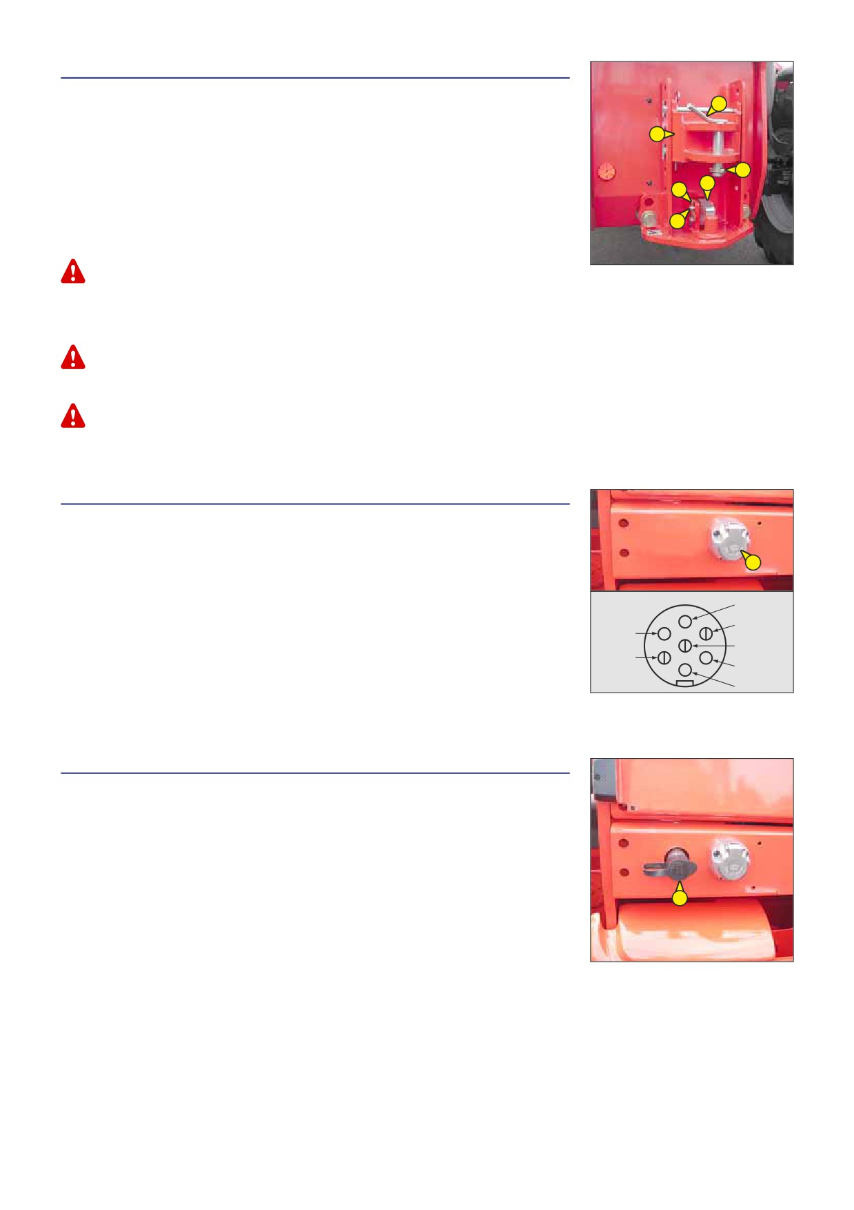
B- COUPLINGLADDER(OPTIONAL)
MT 732 Série D-E3
MT 932 Série D-E3
6
MT 1030 S Série 4-E3
MT 1030 S Turbo Série 4-E3
4
COUPLING AND UNCOUPLING THE TRAILER
5
- To couple the trailer, position the lift truck as close as possible to the trailer ring.
3
1
- Put the handbrake on and switch off the I.C. engine.
ON THE FIXED PIN
2
- Remove pin 1, remove rod 2 and raise latch 3.
- Insert or remove the trailer ring, lower latch 3 and refit rod 2.
Be careful not to get your fingers caught or crushed during this operation.
Do not forget to put clip 1 back in place.
When uncoupling, make sure that the trailer is supported independently.
ON THE COUPLING LADDER
- Set the coupling fitting 4 according to the height of the trailer ring.
Do not forget to put rods and clip back in place.
- Remove the clip 5, lift the trailer pin 6 and place or remove the trailer ring.
Be careful not to get your fingers caught or crushed during this operation.
Do not forget to put clip 5 back in place.
When uncoupling, make sure that the trailer is supported independently.
C- REARELECTRICSOCKET (OPTION)
MT 732 Série D-E3
MT 932 Série D-E3
MT 1030 S Série 4-E3
1
MT 1030 S Turbo Série 4-E3
- Connect the male plug to the female socket 1 on the lift truck and make sure the lights
A
of the trailer or the light bar are working properly.
A - Left rear indicator.
B
F
B - Rear fog lights.
G
C - Earth.
E
C
D - Right rear indicator.
E - Rear lights.
D
F - Rear stoplight.
G - Reversing light.
D- CONNECTINGTHE BRAKE SYSTEM(OPTION)
MT 1030 S Série 4-E3
MT 1030 S Turbo Série 4-E3
- Connect the brake hose to the provided brake unit 1 on the lift truck.
- Make sure the trailer brakes are working properly and test the effects of braking before
taking the trailer onto the public highway.
1
2-59

DESCRIPTION AND USE OF THE OPTIONS
1 - BATTERY CUT-OFF
MT 732 Série D-E3
MT 932 Série D-E3
MT 1030 S Série 4-E3
MT 1030 S Turbo Série 4-E3
1
2 - NUMBERPLATE
MT 732 Série D-E3
MT 932 Série D-E3
MT 1030 S Série 4-E3
MT 1030 S Turbo Série 4-E3
2
3
3
3 - NUMBERPLATE LIGHTING
MT 732 Série D-E3
MT 932 Série D-E3
MT 1030 S Série 4-E3
MT 1030 S Turbo Série 4-E3
4 - PREHEATINGELEMENT
MT 732 Série D-E3
MT 932 Série D-E3
MT 1030 S Série 4-E3
MT 1030 S Turbo Série 4-E3
Enables the engine to be kept warm during prolonged periods of stoppage and thus
improves engine starting.
4
SUPPLY CHARACTERISTICS OF PREHEATING SYSTEM:
• Rated range of power: 220-240V; 50-60Hz
• Current consumed: 4,5A
• Equipment in class 1
• Equipment connectable only on feeder circuit TT or TN
• Categor y of insulation 2
ENVIRONMENTAL CONDITIONS FOR USE:
• Maximum ambient temperature for using preheating: +25° C
• Pollution level 2
CONDITIONS FOR CONNECTION AND USE OF PREHEATING:
- The preheating system should not be used for an external ambient temperature higher than + 25° C.
- It is essential that the power supply to the preheating system is:
• Effected with a cable that conforms to the installation standards in force and contains a protective earth conductor.
• Contains an appropriate sectioning system.
• Incorporate an appropriate safety system against short circuits (fuses or circuit breaker) and a differential circuit breaker
with 30 mA sensitivity.
- Only connect to and disconnect from the power supply while the unit is off and the I.C. engine is stopped.
2-60

5 - MODCODANTI-THEFT SYSTEM
OPERATION
- Switch on the lift truck: the red indicator 1 will flash.
2
1
- Enter your user code followed by “V” to validate: the green indicator 2 will come on.
- Start the lift truck within the next
60 seconds; other wise the anti-theft system will
be reactivated and the red indicator 1 will flash.
NOTE: If you make a mistake when entering the code, press key “A” to cancel and re-
enter the code in full.
If you wait more than 5 seconds between key presses or do not complete entering
the code, the anti-theft system will be reactivated and the red indicator will flash.
6 - FINTRONICANTI-START SYSTEM
OPERATION
- Switch on the lift truck and set the black key A next to the antenna B (maximum 80 mm).
C
- Wait a few seconds for red LED C to go out before starting the lift truck.
NOTE: You can restart the lift truck within 20 seconds of stopping it: after this time, the
anti-start system reacts and LED C flashes red.
B
A
7 - ELECTRICAL PROVISIONONBOOM
Enables an electrical function to be used at the head of the boom.
MT 732 Série D-E3
MT 932 Série D-E3
OPERATION
- Hold down button 1 and move the lever to the left or right.
1
MT 1030 S Série 4-E3
MT 1030 S Turbo Série 4-E3
OPERATION
- Hold down button 1 and move the lever to the left or right.
1
2-61

8 - QUICK-RELEASE COUPLERONATTACHMENT CIRCUIT
MT 732 Série D-E3
MT 932 Série D-E3
MT 1030 S Série 4-E3
MT 1030 S Turbo Série 4-E3
9 - EXTERIORDRAIN-BACK
MT 732 Série D-E3
MT 932 Série D-E3
MT 1030 S Série 4-E3
MT 1030 S Turbo Série 4-E3
Enables connection of an attachment for which drain-back is required.
10 - HYDRAULIC ATTACHMENT LOCKING
MT 732 Série D-E3
MT 932 Série D-E3
MT 1030 S Série 4-E3
MT 1030 S Turbo Série 4-E3
Enables attachment locking to be controlled on the carriage and the use of a hydraulic
attachment on the same hydraulic circuit (see: 4 - OPTIONAL ATTACHMENTS FOR USE WITH
THE RANGE: PICKING UP THE ATTACHMENTS).
2-62

11 - ELECTROVALVE ON BOOM HEAD
Enables use of two hydraulic functions on the attachment circuit.
To make connection of the rapid connectors easier, decompress the hydraulic circuit by pressing button 1
on the electrovalve.
MT 732 Série D-E3
MT 932 Série D-E3
OPERATION
- Without pressing Button 1, the lever controls a hydraulic function.
- Hold button 1 down, the lever controls another hydraulic function.
1
MT 1030 S Série 4-E3
MT 1030 S Turbo Série 4-E3
OPERATION
- Without pressing Button 1, the lever controls a hydraulic function.
- Hold button 1 down, the lever controls another hydraulic function.
1
12 - BOOM HEAD ELECTROVALVE + HYDRAULIC ATTACHMENT LOCKING
MT 732 Série D-E3
MT 932 Série D-E3
MT 1030 S Série 4-E3
MT 1030 S Turbo Série 4-E3
The addition of these two options enables the combining of several hydraulic functions.
2-63

13 - CUTTING OFF “SIMPLE” HYDRAULIC MOVEMENTS
A
The function which cuts hydraulic movements is used to automatically stop dangerous
movement of the boom when you are close to the limit of longitudinal stability. However,
lateral stability can reduce the load chart in its upper part and this reduction is not detected
A1
by the longitudinal stability alarm.
B
B1
NOTE: Since Januar y 2010, Simple movement cut-off is fitted as standard.
The operator must respect the lift truck’s load chart.
All attachments with a suspended load (winch, crane boom, crane boom with winch, hook, etc.) MUST
be used with a lift truck equipped with a working hydraulic movement cut-out device.
OPERATION
Switch A allows you to cut off “SIMPLE” hydraulic movements or not. The cutting-off of
“SIMPLE” hydraulic movements is automatically enabled when the lift truck is started-up.
WITH CUT-PUT OF “SIMPLE” HYDRAULIC MOVEMENTS: VISUAL INDICATOR A1 OFF:
- Led B1 indicates that the lift truck has reached the authorized limit of longitudinal stability and all hydraulic movements are
neutralized.
- The sound alarm goes off at the same time.
- To restart hydraulic movement, proceed as follows:
- Press the bottom of switch A, visual indicator A1 comes on and indicates that the hydraulic movement cut-out is disabled.
- Only per form de-aggravating hydraulic movements in the following order: boom retracted and raised.
- Re-enable the hydraulic movement cut-out by pressing the top of switch A, visual indicator A1 will go out.
NOTE: When the boom is retracted, the function for switching off “SIMPLE” hydraulic movements is disconnected.
WITHOUT CUTTING-OUT “SIMPLE” HYDRAULIC MOVEMENTS: VISUAL INDICATOR A1 ON:
- To allow the use of loading or earth moving buckets, for example.
- In this case, the user is only informed by the longitudinal stability alarm system B (see: 2 - DESCRIPTION: 4 - LONGITUDINAL STABILITY
ALARM SYSTEM).
14 - CUTTING OFF “AGGRAVATING” HYDRAULIC MOVEMENTS
A
The function which cuts hydraulic movements is used to automatically stop dangerous
movement of the boom when you are close to the limit of longitudinal stability. However,
lateral stability can reduce the load chart in its upper part and this reduction is not detected
A1
by the longitudinal stability alarm.
B
B1
The operator must respect the lift truck’s load chart.
All attachments with a suspended load (winch, crane boom, crane boom with winch, hook, etc.) MUST
be used with a lift truck equipped with a working hydraulic movement cut-out device.
OPERATION
Switch A allows you to cut-off “AGGRAVATING” hydraulic movements or not. The cutting-off
of “AGGRAVATING” hydraulic movements is automatically enabled when the lift truck is
started-up.
WITH CUT-OUT OF “AGGRAVATING” HYDRAULIC MOVEMENTS: VISUAL INDICATOR A1 OFF:
- Led B1 indicates that the lift truck has reached the authorized limit of longitudinal stability and all aggravating hydraulic movements
are neutralised.
- The sound alarm goes off at the same time.
- To restart hydraulic movements, only per form de-aggravating hydraulic movements in the following order: boom retracted and
raised.
NOTE: When the boom is retracted, the function for switching off “AGGRAVATING” hydraulic movements is disconnected.
WITHOUT CUTTING-OUT “AGGRAVATING” HYDRAULIC MOVEMENTS: VISUAL INDICATOR A1 ON:
- To allow the use of loading or earth moving buckets, for example.
- In this case, the user is only informed by the longitudinal stability alarm system B (see: 2 - DESCRIPTION: 4 - LONGITUDINAL
STABILITY ALARM SYSTEM).
2-64
///////////////////////////////////////