CG958G Wheel Loader. Manual - part 16
 

  Index      loaders     SICHUAN CHENGDU CHENGGONG CG958G Wheel Loader - service manual


Search            


Content   ..  14  15  16  17   ..


CG958G Wheel Loader. Manual - part 16


- 68 - 

4. Selector valve: 7130-B 


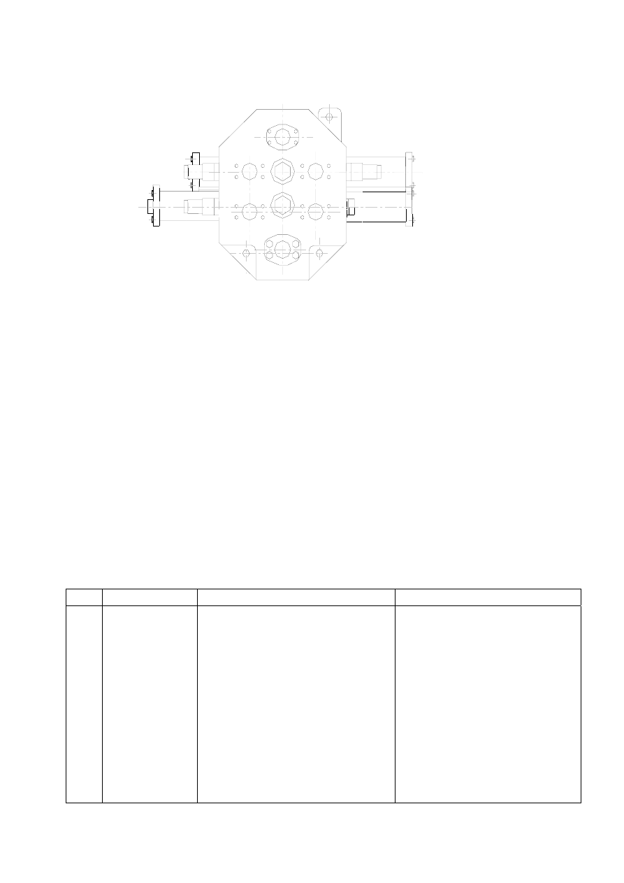
The selector valve adopted for the loader is pilot-controlled hydraulic multi-path change valve, mainly 

consisting of tipping couplet, are moving couplet, main overflow valve, overload valves, inlet check valve, oil 

filling valve for movable arm chamber, etc. System pressure is adjusted via overflow cock at the inlet. 

Tipping couplet is equipped with two overload valves to protect tipping cylinder and pipelines. 

When the selector valve plug is in neutral position, oil inlet and outlet are connected, so there is no operation 

of working unit. 

Turn the tipping handle, pressure oil in proportion to travel is output by pilot-controlled valve to apply a force 

on one end of selector valve plug to slowing reverse the plug. As pressure gradually accumulates at oil inlet 

of selector valve, oil inlet check valve is opened, and pressure oil enters working port to activate working 

unit. 

III. Troubleshooting of working hydraulic system 

No. Symptoms 

Causes 

Solutions 

A Insufficient 

lifting 

force of movable 

arms or 

insufficient bucket 

turning force   

1. Cylinder oils seal is damaged 

2. Clearance between selector valve rod 

and valve body exceeds limits due to 

overwearing 

3. Oil leakage in piping system 

4. Severe internal leakage of working 

pump 

5. Low pressure at safety valve 

1. Replace oil seal 

2. Replace selector valve or check 

and repair valve plug 

3. Check for cause of leakage and 

eliminate it 

4. Replace working pump 

5. Adjust system to nominal value 

6. Replace oil and clean oil filter 

- 69 - 

6. Oil intake line or oil filter is jammed 

7. Low pilot pressure causes insufficient 

reversing of selector valve 

8. Severe internal leakage of the pump 

delivering oil to pilot-controlled 

valve 

7. Adjust pilot pressure to nominal 

value 

B Slow  bucket 

turning or slow 

lifting of movable 

arms at high rpm 

1. See causes in A 

2. Overload valve is blocked 

1. See solutions in A 

2. 

Replace or check and repair 

overload valve 


1.3.2 Brake system 

The loader adopts original pedal brake valve (06-466-240) and refill valve (06-463-230) manufactured by 

MICO USA. Refer to Installation and Service Manual of MICO Products – Two-way Refill Valve and 

Installation and Service Manual of MICO Products – Two-way Serial Pedal Valve for details. 

Accumulator and brake valve manufactured by HYDAC are adopted. 


1.3.3 Structure and operating principle of hydraulic steering system 

1. Diagram of hydraulic steering system 


- 70 - 


(1). Pump: T6DCM-B24-B05-3R23-C1, (2). Check valve: DIF-L32H, (3). Priority steering control valve: 

VLE-150/882-5902-059, (4) Steering gear: BZZ1-1000(FK-0/20)550-7286/831-2604, (5). Steering cylinder: 

CL90X45/488 EG-00A (6). Emergency steering power unit: 12869-00, (7). Check valve: DIF-L10H 

(Note: pressure tap 1 is for measuring oil intake pressure, pressure tap 2 for measuring outlet, and pressure 

tap 3 for measuring steering pressure) 


2. Schematic diagram of hydraulic steering system 

- 71 - 


3. Steering system adopts a load-sensing hydraulic steering mechanism mainly consisting of pump, 

load-sensing steering gear, priority steering control valve, steering cylinder, emergency steering power unit, 

check valves and pipelines. System cleanliness is controlled within Grade NAS1683 9. 

LS pipeline transfers internal pressure signal from steering gear to priority valve to achieve balance of the 

valve plug, thus ensuring the flow rate required by port CF. 

Load-sensing hydraulic steering system has the following features: 


Content   ..  14  15  16  17   ..