CG938H Wheel Loader. Manual - part 14
 

  Index      loaders     SICHUAN CHENGDU CHENGGONG CG938H Wheel Loader - service manual


Search            


Content   ..  12  13  14  15   ..


CG938H Wheel Loader. Manual - part 14


58

1.2 Profile and Major Parameters 


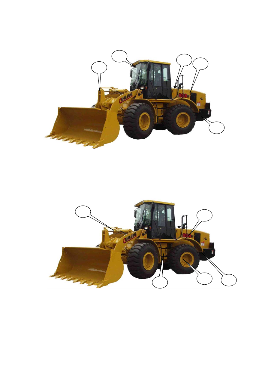
Engine (1), Fuel tank (2), Hydraulic oil tank (3), Working unit (4), Cab (5), 


Heat radiator (6), Gearbox (7), Driving axle (8), Batteries (9), Gas tank (10) 


3

5

8

10


59

Major Parameters and Dimensions 

Rated 

engine 

power: 

           116kW 

Rated 

engine 

speed: 


          2200r/min 

Rated 

bucket 

capacity: 


          2.1m

3


Rated 

loading 

capacity: 


          3.8t 

Dump height:   (bucket blade /tip)                       2949 mm/2786mm 

Unloading distance at maximum dump height from (bucket blade/tip): 923mm/1041mm 

Lift time of movable arms:                                                              <4.7 

Total of “three time” of working unit:                                                    <9.6s 

Steering angle:                                                                      ±35° 

Turning radius:                                   5200mm 

Maximum traveling speed::                                                    >34km/h  

Length:                                       7330mm 

Width:                                        2675mm 

Height:                                       3300mm 

Operating Mass:                                      12.5t 

Oil pressure in working hydraulic system:                                                        19MPa 

Oil pressure in steering hydraulic system:                                              16MPa 

All the above parameters are measured on a loader horizontally parked on hard supporting ground. 

The operator should pay attention in operation to limits of various operating conditions, such as soft 

ground, slope or unbalanced carrying, and correspondingly adopt proper operating mode. 

1.3 Scope of Work and Configuration 

As one of major construction machines, loader is widely used in bucketing, conveying, unloading and leveling 

operation of loose materials in addition to light-duty cutting. 

The working unit of the loader is independently designed and developed by Chenggong with a self-made standard 

bucket. Loading weight of the loader should not exceed 3.8 tons. 

The loader is equipp

d with QSB6.7 engine

 manufactured by Cummins Engine Company, Ltd. 

Torque-converting gearbox is ZF4WG158 manufactured by ZF Liuzhou Company. 

Front and rear driving axles are manufactured by Chenggong. 

1.3.1 Description of Implement System 

I. System principle: 


60


II System description: 

The loader adopts pilot-controlled working hydraulic system with pilot oil coming from 

delivery side of steering pump. A locking electromagnetic valve is installed on pilot-controlled 

delivery valve which is powered off when not working. In this case, operation of pilot handle will 

not activate working unit for safety purpose. Under working status, the locking electromagnetic 

valve is powered on and the operation of pilot handle will activate the reversing of selector valve 

plug to realize lifting, lowering of working unit and bucket retracting and tipping, etc. 

Pilot system accumulator keeps the pressure at a certain level. In case of sudden breakdown of 

engine, place pilot handle to lowering position so that the hydraulic oil in accumulator applies a 

force on valve plug through pilot-controlled valve to lower the movable arms. 

In the system, a driving control block, also called as vibration reduction module, is designed. 

This module leads the oil circuit of the lift cylinder to the accumulator through a switch valve and 


61

absorbs the load due to dump during driving so as to enable the loader to have a better performance, 

higher speed, rapid transportation, better shifting performance and shorter braking distance etc. 

III. Features of Components 

1. Working pump 3520VQS21A12-297DD20R 

Working pump is a vane pump; refer to introduction in steering hydraulic system for its 

structure and operating principle. 

2. Pilot-controlled delivery valve  Structure and operating principle of pilot-controlled 

delivery pump are shown in the figure above. Ports P1 and P2 are connected to pump source, port 

PR is connected to oil inlet of pilot-controlled valve while port PV serves as the pressure tap of pilot 

system. As the locking electromagnetic valve for pilot handle, when electromagnetic valve is 

powered off, there is no hydraulic oil pass through pilot system to prevent misoperation of handle 

from causing safety problems. 


3. Pilot-controlled valve 406-1044-1145 

Pilot-controlled valve is a monolevered true motion relief valve integrating oil inlet, oil outlet, tipping port, 

retracting port, lifting port and lowering/floating port, etc. The position of pilot handle controls the travel of 

pilot-controlled valve plug, which is in proportion to the pressure at corresponding port to realize proportional hydraulic 

control over selector valve. Oil inlet of pilot-controlled valve is connected to port PR of pilot-controlled delivery valve 

for oil source. When the handle is turned to a certain angle, oil from port P enters corresponding valve plug end in 

selector valve and push the valve plug to achieve retracting, tipping, lifting and lowering operations. Electromagnet 


Content   ..  12  13  14  15   ..