Diesel engine 12V 4000 G73, 16V 4000 G73. Manual - part 36
 

  Index      Engines     Diesel engine 12V 4000 G73, 16V 4000 G73. Application group 3B - service manual


Search            


Content   ..  34  35  36  37   ..


Diesel engine 12V 4000 G73, 16V 4000 G73. Manual - part 36


7.21.5 ECU 7 engine governor – Removal and installation

Preconditions

☑ Engine is stopped and starting disabled.

CAUTION

Wrong engine governor installed.

Engine damage!

• When reassembling an engine, make sure that the governor with the data record for the given

engine is installed.

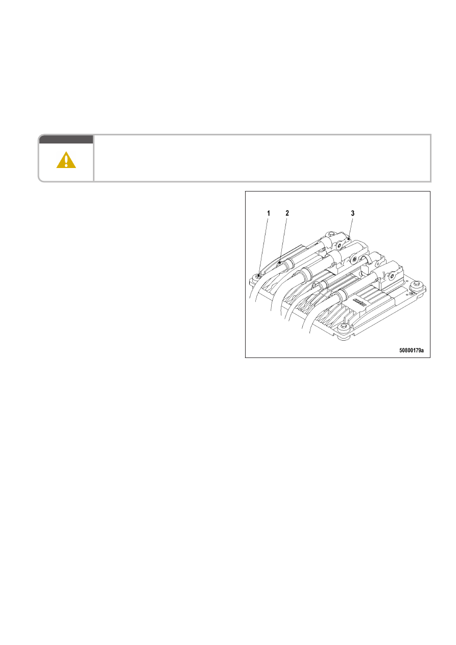
Removing engine governor from

engine

1.

Note or mark assignment of cables and

connectors.

2.

Remove all screws (2).

3.

Undo latches (3) of the connectors.

4.

Remove all connectors.

5.

Remove screws (1).

6.

Take off engine governor.

Installing engine governor on engine

1.

Install in reverse order. In doing so, ensure correct assignment of connectors and sockets.

2.

Check rubber mount before installation.

Result:

If the rubber mount is porous or defective, replace it.

7.21.6 EMU 7 – Removal and installation

Preconditions

☑ Engine is stopped and starting disabled.

CAUTION

Wrong engine governor installed.

Engine damage!

• When reassembling an engine, make sure that the governor with the data record for the given

engine is installed.

Removing ECU with EMU from

engine

1.

Note or mark assignment of cables and

connectors.

2.

Remove all screws (2).

3.

Undo clips (3) on connectors.

4.

Disconnect all connectors.

5.

Remove screws (1).

6.

Remove ECU (1) with EMU (4).

Removing EMU

1.

Undo screws on base of EMU (4).

2.

Remove EMU (4) from ECU (1).

Installing EMU

1.

Place EMU (4) on ECU (1).

2.

Screw in and tighten screws on base of EMU (4).

Installing ECU with EMU on engine

1.

Install in reverse order. Ensure correct assignment of connectors and sockets in so doing.

2.

Check resilient mount before installing.

Result:

Replace resilient mount if porous or defective.

TIM-ID: 0000016799 - 002

8 Appendix A

8.1 Abbreviations

Abbreviation

Meaning

Explanation

A/D

Analog/Digital

Transformer: transforms sensor voltages into

numeric values

ADEC

Advanced Diesel Engine Controller

Engine management system

AFRS

Air Filter Restriction Sensor

ANSI

American National Standards Institute Association of American standardization or‐

ganizations

ATL

Abgasturbolader

Exhaust turbocharger (ETC)

ATS

Air Temperature Sensor

BR

Baureihe

Series

BV

Betriebsstoffvorschrift

MTU Fluids and Lubricants Specifications,

Publication No. A01061/..

CAN

Controller Area Network

Data bus system, bus standard

CDC

Calibration Drift Compensation

Setting of drift compensation in engine gov‐

ernor with DiaSys

CEL

Stop Engine Light

1st function: Warning lamp (rectify fault as

soon as possible)
2nd function: Read out fault codes

CKT

Circuit

CLS

Coolant Level Sensor

Monitors coolant level

CPS

Coolant Pressure Sensor

Monitors coolant pressure

CTS

Coolant Temperature Sensor

Monitors coolant temperature

DDEC

Detroit Diesel Electronic Controls

Engine control system made by Detroit Die‐

sel

DDL

Diagnostic Data Link

Diagnostic lines

DDR

Diagnostic Data Reader

Diagnostic unit

DIN

Deutsches Institut für Normung e. V.

At the same time identifier of German stand‐

ards (DIN = “Deutsche Industrie-Norm”)

DL

Default Lost

Alarm: Default CAN bus failure

DOC

Diesel Oxidation Catalyst

Oxidation catalyst upstream of the diesel

particulate filter

DPF

Diesel Particulate Filter

DT

Diagnostic Tool

Diagnostic unit

ECM

Electronic Control Module

Electronic control unit of the DDEC system

ECU

Engine Control Unit

Engine governor

EDM

Engine Data Module

Memory module for engine data

EEPROM

Electrically Erasable Programmable

Read Only Memory

EFPA

Electronic Foot Pedal Assembly

Abbreviation

Meaning

Explanation

EGR

Exhaust Gas Recirculation

EMU

Engine Monitoring Unit

ETK

Ersatzteilkatalog

Spare Parts Catalog (SPC)

EUI

Electronic Unit Injector

FPS

Fuel Pressure Sensor

Monitors fuel pressure

FRS

Fuel - Differential Pressure Sensor

FTS

Fuel Temperature Sensor

Monitors fuel temperature

FWCP

Fire Water Control Panel

Control cabinet

GND

Ground

HD

Hochdruck

High Pressure (HP)

HI

High

Alarm: Measured value exceeds 1st maxi‐

mum limit

HIHI

High High

Alarm: Measured value exceeds 2nd maxi‐

mum limit value

HT

High Temperature

IDM

Interface Data Module

Memory module for interface data

INJ

Injector

ISO

International Organization for Stand‐

ardization

International umbrella organization for all na‐

tional standardization institutes

KGS

Kraftgegenseite

Engine free end in accordance with DIN ISO

1204

KS

Kraftseite

Engine driving end in accordance with DIN

ISO 1204

LED

Light Emitting Diode

LO

Low

Alarm: Measured value lower than 1st mini‐

mum limit value

LOLO

Low Low

Alarm: Measured value lower than 2nd mini‐

mum limit value

LSG

Limiting Speed Governor

N/A

Not Applicable

LP

Low Pressure

OEM

Original Equipment Manufacturer

OI

Optimized Idle

OLS

Oil Level Sensor

Monitors oil level

OPS

Oil Pressure Sensor

Monitors oil pressure

OTS

Oil Temperature Sensor

Monitors oil temperature

OT

Oberer Totpunkt

Top Dead Center (TDC)

PAN

Panel

Control panel

PIM

Peripheral Interface Module

PWM

Modulated signal

P-xyz

Pressure-xyz

Pressure measuring point, xyz specifies the

measuring point designation

RL

Redundancy Lost

Alarm: Redundant CAN bus failure

TIM-ID: 0000000858 - 009


Content   ..  34  35  36  37   ..