Diesel engine 12V 4000 G73, 16V 4000 G73. Manual - part 23
 

  Index      Engines     Diesel engine 12V 4000 G73, 16V 4000 G73. Application group 3B - service manual


Search            


Content   ..  21  22  23  24   ..


Diesel engine 12V 4000 G73, 16V 4000 G73. Manual - part 23


7.9 Charge-Air Cooling

7.9.1 Intercooler – Check drain for coolant leakage and obstruction

DANGER

Unguarded rotating and moving engine components.

Risk of serious injury – danger to life!

• Take special care when working on a running engine.

WARNING

Engine noise above 85 dB (A).

Risk of damage to hearing!

• Wear ear protectors.

WARNING

Compressed air

Risk of injury!

• Do not direct compressed-air jet at persons.

• Wear protective goggles / safety mask and ear protectors.

Intercooler – Check drain for

coolant leakage and obstruction

1.

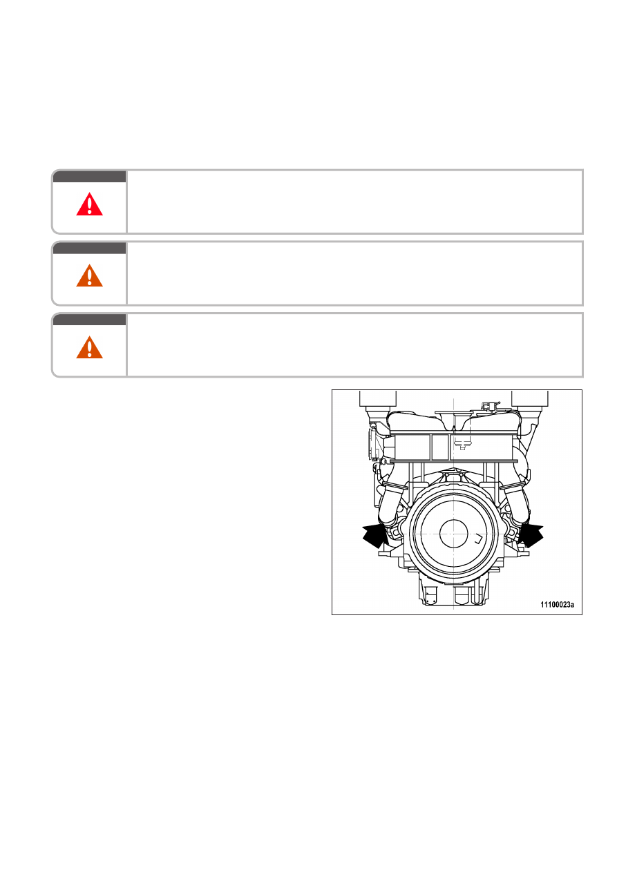
Verify that air emerges from condensate

drain bore(s) on left and right engine sides

at driving end when engine is running. If no

air emerges:

• Clean drain bore(s)

• Blow out with compressed air

2.

If a large amount of coolant is continuously

discharged, the intercooler is leaking. Con‐

tact Service.

Emergency measures prior to engine start with a leaking intercooler

1.

Remove injectors (→ Page 79).

2.

Bar engine manually (→ Page 63).

3.

Crank engine on starting system to blow out combustion chambers (→ Page 64).

4.

Install injectors (→ Page 79).

7.10 Air Filter

7.10.1 Air filter – Replacement

Special tools, Material, Spare parts

Designation / Use

Part No.

Qty.

Air filter

(→ Spare Parts Catalog)

Air filter – Replacement

1.

Remove air filter and install new one (→ Page 95).

2.

Reset signal ring of service indicator (→ Page 97).

TIM-ID: 0000000903 - 004

7.10.2 Air filter – Removal and installation

Preconditions

☑ Engine is stopped and starting disabled.

Air filter – Removal and installation

1.

Release clamp (2).

2.

Remove air filter (3) and clamp (2) from

flange of intake housing (1).

3.

Verify that there are no objects in the flange

of the intake housing (1) and clean it.

4.

Place new air filter (3) with clamp (2) onto

intake housing (1).

5.

Tighten clamp (2).

7.10.3 Rubber sleeves between air intake elbow and turbocharger – Replacement

Preconditions

☑ Engine is stopped and starting disabled.

Special tools, Material, Spare parts

Designation / Use

Part No.

Qty.

Rubber sleeve

(→ Spare Parts Catalog)

4

Also applicable to 12 V

Preparatory steps

u

Remove air filter (→ Page 94).

Replacing rubber sleeves

1.

Remove screws (3), loosen clamps (1) and take off elbow (4).

2.

Pull off rubber sleeve (2) from turbocharger intake flange.

3.

Clean connecting flange of turbocharger and check for obstructions.

4.

Fit new rubber sleeve (2) on turbocharger intake flange.

5.

Fit both clamps (1) on rubber sleeve (2), slide on elbow (4) and secure with screws (3).

6.

Align clamps (1) and tighten.

7.

Replace further rubber sleeves in the same way.

Final steps

u

Install air filter (→ Page 94).

TIM-ID: 0000013404 - 002


Content   ..  21  22  23  24   ..