Diesel engine 12V 4000 G73, 16V 4000 G73. Manual - part 20
 

  Index      Engines     Diesel engine 12V 4000 G73, 16V 4000 G73. Application group 3B - service manual


Search            


Content   ..  18  19  20  21   ..


Diesel engine 12V 4000 G73, 16V 4000 G73. Manual - part 20


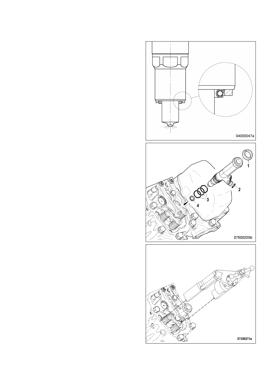
Installing injector

1.

Remove plug before installing the injec‐

tor. (Do not remove the plug from the HP

line before installing the adapter.)

2.

Coat injector with assembly paste at the

seat of the nozzle clamping nut.

3.

Fit new sealing ring (4) (included in the

scope of supply of the injector) with grease

on injector, observe installation position of

sealing ring (4).

4.

Fit new O-rings (3) (included in the scope of

supply of the injector), O-ring (2) and damp‐

ing ring (1) onto the injector and coat with

grease.

5.

Clean sealing face on cylinder head and

protective sleeve with milling cutter.

6.

Insert injector into cylinder head, ensuring

that the HP line adapter is correctly aligned.

7.

Use installation/removal tool to press in in‐

jector.

8.

Remove installation/removal tool.

9.

Coat screw head mating face (2) and

thread with engine oil.

10.

Fit hold-down clamp (1) in the correct position and use torque wrench to tighten screw (2) to the specified

initial tightening torque.

Name

Size

Type

Lubricant

Value/Standard

Screw

M12

Preload torque

(Engine oil)

5 Nm to 10 Nm

Note:

Ensure special cleanness.

11.

Coat thread and sealing cone of adapter (3) with engine oil.

12.

Install adapter (3) and use torque wrench to tighten to the specified initial tightening torque.

Name

Size

Type

Lubricant

Value/Standard

Adapter

Preload torque

(Engine oil)

5 Nm to 10 Nm

13.

Tighten screw (2) with torque wrench to the specified tightening torque.

Name

Size

Type

Lubricant

Value/Standard

Screw

M12

Tightening torque

100 Nm + 10 Nm

14.

Tighten adapter (3) with torque wrench to the specified tightening torque.

Name

Size

Type

Lubricant

Value/Standard

Adapter

Tightening torque

100 Nm + 10 Nm

15.

Install return line (7).

Note:

Ensure special cleanness.

16.

Coat thread and sealing cone of HP line (5) with engine oil.

Note:

Two HP line versions (single- and double-walled) with different torques as described below.

17.

Mount single-walled HP line (5) and use torque wrench to tighten to the specified torque. Tightening se‐

quence:

1 Rail (6)

2 Adapter (4)

Name

Size

Type

Lubricant

Value/Standard

Union nut / thrust

screw

Tightening torque

30 Nm + 5 Nm

TIM-ID: 0000000925 - 006

18.

Mount double-walled HP line (5) and use torque wrench to tighten to the specified torque. Tightening

sequence:

1 Adapter (4)

2 Rail (6)

Name

Size

Type

Lubricant

Value/Standard

Union nut / thrust

screw

Tightening torque

40 Nm + 5 Nm

19.

Fit cable connector onto injector.

Final steps

1.

Install cylinder head cover (→ Page 76).

2.

Open fuel supply to engine.

7.7 Fuel System

7.7.1 Fuel system – Venting

Preconditions

☑ Engine is stopped and starting disabled.

Special tools, Material, Spare parts

Designation / Use

Part No.

Qty.

Diesel fuel

WARNING

Fuels are combustible.

Risk of fire and explosion!

• Avoid open flames, electrical sparks and ignition sources.

• Do not smoke.

Venting LP fuel system

1.

Open threaded vent plug (1).

2.

Unlock fuel priming pump (2), screw out

handle by turning it counterclockwise.

3.

Operate the pump with the handle (2) until

bubble-free fuel emerges at the threaded

vent plug (1).

4.

Close threaded vent plug (1).

5.

Screw in handle by turning it clockwise.

6.

Verify that fuel priming pump (2) is locked:

Handle must be tightened.

TIM-ID: 0000004709 - 005


Content   ..  18  19  20  21   ..