Diesel engine 12V 4000 G73, 16V 4000 G73. Manual - part 18
 

  Index      Engines     Diesel engine 12V 4000 G73, 16V 4000 G73. Application group 3B - service manual


Search            


Content   ..  16  17  18  19   ..


Diesel engine 12V 4000 G73, 16V 4000 G73. Manual - part 18


7.4.2 Valve clearance – Check and adjustment

Preconditions

☑ Engine is stopped and starting disabled.
☑ Engine coolant temperature is max. 40 °C.
☑ Valves are closed.

Special tools, Material, Spare parts

Designation / Use

Part No.

Qty.

Feeler gauge

Y20010128

1

Torque wrench, 60-320 Nm

F30047446

1

Ring socket, 24 mm

F30039526

1

Preparatory steps

1.

Remove cylinder head cover (→ Page 76).

2.

Install barring device (→ Page 63).

3.

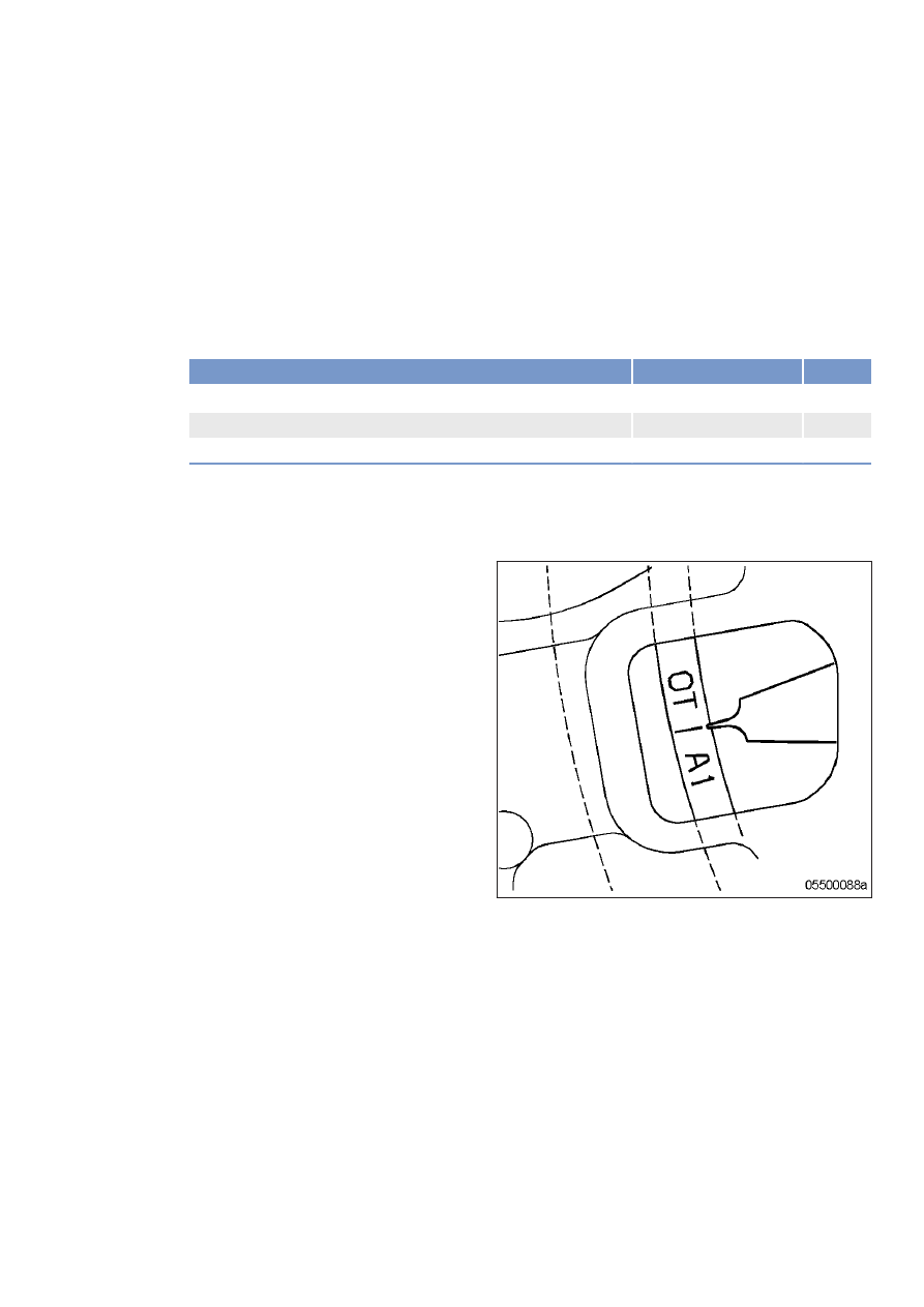
Rotate crankshaft with barring device in en‐

gine direction of rotation until "OT-A1" mark

and pointer are aligned.

Diagram for 12V engines (two

crankshaft positions)

Diagram for 16V engines (two

crankshaft positions)

Checking valve clearance at two crankshaft positions

1.

Check TDC position of piston in cylinder A1:

• If the rocker arms are unloaded on cylinder A1, the piston is in firing TDC.

• If the rocker arms are under load on cylinder A1, the piston is in overlap TDC.

2.

Check valve clearance with cold engine:

• Inlet valves (long rocker arm) = 0.2 mm

• Exhaust valves (short rocker arm) = 0.5 mm

3.

Check all valve clearances in two crankshaft positions (firing TDC and overlap TDC of cylinder A1) as

per diagram.

1 Cylinder A1 is in firing TDC

2 Cylinder A1 is in overlap TDC

I Inlet valve

X Exhaust valve

4.

Use feeler gauge to determine the distance between valve bridge and rocker arm.

5.

If the deviation from the reference value exceeds 0.1 mm, adjust valve clearance.

TIM-ID: 0000012221 - 003

Adjusting valve clearance

1.

Release locknut (1).

2.

Insert feeler gauge between valve bridge

and rocker arm.

3.

Using Allen key, set adjusting screw (2) so

that the specified valve clearance is provid‐

ed.

4.

Feeler gauge must just pass through the

gap.

5.

Tighten locknut (1) to 90 +9 Nm, holding

adjusting screw (2) firmly.

6.

Replace or rectify adjusting screws and/or

locknuts which do not move freely.

7.

Check valve clearance.

Final steps

1.

Remove barring device (→ Page 63).

2.

Install cylinder head cover (→ Page 76).

7.4.3 Cylinder head cover – Removal and installation

Preconditions

☑ Engine is stopped and starting disabled.

Special tools, Material, Spare parts

Designation / Use

Part No.

Qty.

Grease (Kluthe Hakuform 30-10/Emulgier)

X00058061

O-ring

(→ Spare Parts Catalog)

Removing cylinder head cover

1.

Clean very dirty cylinder head covers (3)

prior to removal.

2.

Remove screws (1) and washers (2).

3.

Take off cylinder head cover (3) with O-

ring (4) from cylinder head (5).

Installing cylinder head cover

1.

Clean mounting surface.

2.

Check O-ring (4) for damage, replace if necessary.

3.

Coat O-ring (4) with grease.

4.

Position O-ring (4) in groove of cylinder head cover (3).

5.

Fit cylinder head cover (3) on cylinder head (5).

6.

Install cylinder head cover (3) with screws (1) and washers (2).

TIM-ID: 0000012309 - 007


Content   ..  16  17  18  19   ..