Kawasaki Diesel MULE 4010 TRANS 4x4 (KAF950G9). Manual - part 79
 

  Index      Engines     Kawasaki Diesel MULE 4010 TRANS 4x4 (KAF950G9) - service manual


Search            


Content   ..  77  78  79  80   ..


Kawasaki Diesel MULE 4010 TRANS 4x4 (KAF950G9). Manual - part 79


12-38 FINAL DRIVE

Drive Shaft and Axles

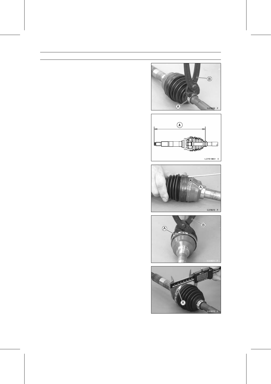
Pinch the small boot band [A] with a suitable tool [B] to
install it.

Compress the axle assembly to the specified length while
relieving the air pressure inside the boot.

Hold the axle at this setting.

Standard Length of Assembling:

Outboard:

254.5 mm (10.020 in.) [A]

Slightly open [A] the larger diameter end of the joint boot
to equalize the air pressure inside the boot.

Pinch the boot bands [A] with a suitable tool [B] to install
it.

Compress the suitable tool with a vice, if necessary.

Be sure outside diameter of the band [A] is less than the
maximum diameter.

Maximum Outside Diameter of Band: 75.9 mm (2.99 in.)

FINAL DRIVE 12-39

Drive Shaft and Axles

Inboard Joint Boot Removal

Remove:

Front Axle (see Front Axle Removal)
Circlip [A]

Special Tool - Outside Circlip Pliers [B]: 57001-144

Remove:

Collar [C]
Cap [D]

Remove:

Front Axle (see Front Axle Removal)

Tap the joint portion of the bands [A] with a suitable tool.

Scrap the removed boot bands.

Slide the joint boot [B] toward the outboard joint.

Remove the retaining ring [A].

Separate the bearing cup from the axle shaft.

Remove the steel balls [A].

Slide the cage [B] toward the outboard joint.

Remove:

Circlip [A]

Special Tool - Outside Circlip Pliers [B]: 57001-144

12-40 FINAL DRIVE

Drive Shaft and Axles

Remove:

Inner Race [A]
Cage [B]
Inboard Joint Boot [C]

Inboard Joint Boot Installation

Install:

New Small Band [A]
New Inboard Joint Boot [B]
Cage [C]

Install the inner race [A] so that the flat serration side [B]
faces outboard joint.

Install:

Circlip [A]

Special Tool - Outside Circlip Pliers: 57001-144

Slide the cage [B] on the inner race and install the steel
balls [C].

Apply the special grease [A] to the steel balls and cage.

FINAL DRIVE 12-41

Drive Shaft and Axles

Squeeze about half a tube (30 grams) of the special
grease [A] into the bearing cup [B].

Insert the balls and cage assembly in the bearing cup
strongly.

Install the axle shaft [A] into the bearing cap [B].

Install the new retaining ring [A] so that the opening [B] is
aligned with one of the projections [C].

Squeeze the remaining special grease into the bearing
cup [A] and new joint boot [B].

Pinch the small boot band [A] with a suitable tool [B] to
install it.


Content   ..  77  78  79  80   ..