Hyundai Diesel Generator. Manual - part 3
 

  Index      Engines     Hyundai Diesel Generator - service manual


Search            


Content   ..  1  2  3  4   ..


Hyundai Diesel Generator. Manual - part 3


User manual 


1~1.5  m  of  distance  from  the  generator  set  and 
1.5~2m above the generator set. 

The  generator  set  working  room  shall  be  furnished 

with  fire  extinguish  hydrant  which  conform  to  the 
specified standard. 

Emergency  lighting  facilities  shall  be  installed  in  the 

generator  set  working  room  for  the  convenience  of 
operation and maintenance. 

No  combustible  and  explosive  materials  are  allowed 

to be placed in the generator set working room. 

Below is the layout for the open system generator set 
working room. 

(Foundation drawing Refer to APPENDIX B ) 


Note:   
Our  company  can  make  drawings  and  design 
installation  dimensions  for  generator  set  working 
room according to customer’s special requirements.


Below is the layout for the canopy system generator 
set working room. 

(Foundation drawing Refer to APPENDIX C ) 


Note:   
Canopied  generator  set  can  work  outdoor  directly.  If 
users  wants  to  operate  the  generator  set  indoor, 
above  diagram  can  be  taken  as  reference.  we  can 
design the layout of generator set working room and 
installation dimension according to customer’s special 
requirements. 


2.5


Installation of Generator Set 

2.5.1


Locate the position of generator set


Vibration  reduction  units  have  been  installed  on  our 
generator  sets  (except  a  few  generator  sets  don’t 
have this kind of facility). Users can take reference on 
the  installation  diagram,  correctly  install  the 
generator set on a flat and hard foundation, use the 
expansion bolts to tightly fix the generator set to the 
concrete foundation through the installation holes on 
the  base  frame.  When  no  special  requirement  is 
needed,  we  don’t  suggest  customers  to  install 
additional vibration reduction units. 

Soft connection is needed to connect the parts of the 
generator  set  to  outside.  For  example:  corrugated 
vibration  reduction  pipe  has  been  used  to  connect 
exhaust  pipes,  air  exhaust  path,  fuel  inlet  pipe,  fuel 
return  pipe  and  busbar  cable  etc.,  all  of  these  parts 
need to use soft connections. Only in this way we can 
reduce the adverse effect caused by the vibration of 
generator set to the minimum extent. 

2.5.2


Ventilation     


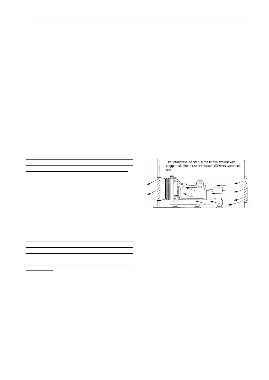
When a generator set with a complete set of radiator 
assembly has been installed in the working room, the 
basic  principle  is  to  discharge  the  hot  air  in  the 
working  room  to  outside  and  let  in  the  low 
temperature  air  from  outside,  and  try  you  best  to 
avoid the hot air come in from outside. 
The diagram in the right side demonstrates the ideal 
position of a generator set in the working room. 
The  purpose  of  this  arrangement  is  to  get  cold  air 
from the lowest point as much as possible, and force 
them to pass through the radiator core, and then lead 
them out. 


Users  can  use  metal  plate  or  canvas  to  make  a  wind 
guide  cover,  the  connection  between  wind  guide 
cover  and  the  radiator  shall  be  soft  connection,  so 
that to cut off the transmission of vibration from the 
generator set, and also ensure the hot air exhaust to 
outside thoroughly. 
The  effective  circulation  sectional  area  inside  of  the 
wind  guide  cover  shall  be  bigger  than  1.25  times  of 
the front face area of the radiator core. And the wind 
guide  cover  shall  be  smooth,  no  sharp  angle  and 
camber so that to reduce the resistance to the wind. 
At  the  same  time,  the  effective  circulation  sectional 
area in the air inlet opening shall also be bigger than 
1.25 times of the front face area of the radiator core. 
When the users have installed mesh cover or shutters 
in  the  air  inlet  /outlet  opening  or  there  is  too  many 
cambers  in  the  air  inlet/outlet  opening,  the  effective 
air  circulation  sectional  area  will  be  reduced  and 
resistance  will  increase,  and  therefore,  it’s  necessary 
to further increase air circulation area. 


User manual 


Under  normal  conditions,  the  air  volume  generated 
from  the  radiator’s  fan  is  enough  to  meet  the 
requirement of the working room ventilation.   
The air inlet temperature of the engine shall be below 
30  degree  Celsius.  If  the  air  inlet  temperature  keep 
rising  above  30  degree  Celsius,  the  engine’s  output 
power  will  be  reduced,  and  therefore  fresh  air  from 
outside  shall  be  introduced  into  the  generator  set’s 
working room in a timely manner. 
If  the  generator  set  is  furnished  with  a  remote 
radiator,  forced  air  circulation  for  the  generator  set 
working  room  is  a  must.  The  forced  air  circulation 
need  two  fans,  one  fan  is  responsible  for  air  intake, 
another  is  air  exhaust,  which  exhausts  hot  air  to 
outside. 
When the engine is furnished with propelled fan, it is 
recommended  that  a  separate  pipe  is  needed  to 
exhaust the gas which generated from the crankcase 
to  outside.  Otherwise  the  exhaust  gas  from  the 
crankcase will accumulate on the radiator, which will 
cause  the  radiator  stuck  by  dirty  material,  and  as  a 
result, the heat‐sinking capacity will be reduced. 


2.5.3


Exhaust 

Our  standard  configuration  diesel  generator  sets 
provide  accessories  such  as  industry  heavy  silencer, 
soft corrugated pipe and elbow etc. Users can design 
the  exhaust  system  of  generator  set  working  room 
by  themselves.  When  design  and  install  the  exhaust 
system, please consider the following aspects: 
Ensure the total exhaust backpressure no higher than 

the  maximum  allowed  value  specified  by  the 
engine(usually  generator  set’s  maximum  exhaust 
backpressure  is  no  more  than  5Kpa)  Fix  the  exhaust 
system  to  make  sure  the  exhaust  manifold  and 
turbo‐charger are not subject to the vertical pressure 

and side stress. 

◆ Reserve  some  space  for  hot  shrinkage  and  cold 

expansion. 

Reserve space for generator set vibration. 
Reduce exhaust noise level. 

Overload  of  exhaust  backpressure  will  cause 
following adverse effect: 

Output power loss 
Fuel efficiency reduce 
Exhaust gas temperature rise 
 
 
Note: 
When  more  than  one  generator  set  are  installed,  try 
not  to  discharge  all  of  the  generator  sets’  gas  from 
one  exhaust  path.  If  no  separated  exhaust  pipe  is 
allowed,  under  the  condition  that  the  total 
backpressure will not exceed the generator sets’ total 
backpressure  a  moveable  separate  panel  shall  be 
installed  inside  of  the  branch  exhaust  pipe  so  that  to 
prevent the gas from return. 
 
 
In  the  exhaust  system,  soft  corrugated  pipe  shall  be 
used  to  connect  the  exhaust  pipe  with  the 
turbocharger,  this  pipe  has  three  functions  as 
follows: 
◆Separate  the  diesel  engine  with  vibration  and  the 

weight of exhaust pipe. 

◆Compensate the heat expansion of exhaust pipe. 
If  the  diesel  generator  set  is  installed  on  the 
anti‐vibration  base  frame,  the  corrugated  pipe  can 
compensate sideway movement when engine start or 
stop. 
 
Note:   
1.  Serious  damage  will  occur  when  rain or  condensed 

water  enter  into  engine’s  exhaust  system. 
Therefore,  one  water  discharge  opening  shall  be 
installed  in  the  long  exhaust  pipe,  the  position  of 
which shall be close to the generator set.   

2.  When  the  top  of  the  exhaust  pipe  is  above  the 

architecture,  lightening  protection  is  needed 
(connect to the ground) 


2.5.4

 Noise reduction


When diesel generator set is running, normally it will 
generate noise level of 90~110dB, and the more the 
load, the higher the noise level.   
In order to meet the noise level standards established 
by the local environmental protection bureau and to 
prevent  the  noise  pollution  caused  to  ambient 
environment,  which  will  affect  people’s  normal  life, 
to  reduce  noise  level  of  diesel  generator  set  is  also 


User manual 


very important. 
Noise  reduction  engineering  is  a  comprehensive  and 
professional  engineering.  During  the  process  when 
users  try  to  design  the  scheme  for  noise  reduction 
project,  at  the  same  time  please  fully  consider  the 
bottom  limit  of  air  inlet/outlet  volume  needed  by 
engine’s  normal  running  and  the  maximum  allowed 
value  for  exhaust  backpressure  etc.  Otherwise,  the 
noise reduction project will seriously affect generator 
set’s  output  power,  and  make  generator  set’  s 
temperature  rise,  cause  frequent  malfunction  of  the 
generator  set,  and  even  it  will  shorten  the  life 
expectancy of generator set. 
 
Note: 
HYUNDAI  Power  can  provide  customers  with  overall 
sound proof generator set. 


2.6


Cooling system


Our standard configuration diesel generator sets are 
closed  cycling  water  chilling  units  with  fan  and 
radiator  installed.  Closed  water  chilling  engine  drive 
the  cooling  pump  to  generate  circulation  power, 
which  keep  the  anti‐freeze  in  the  paths  of  cylinder 
body  and  cover  continuous  circulation  and  heat 
elimination. Engine’s cooling pump, radiator (or heat 
exchanger)  forms  a  closed,  pressure  cycling  and 
cooling system. 
The  most  common  cooling  system  is  cooling  fan 
directly  driven  by  radiator  and  engine,  which  can  be 
replaced  by  heat  exchanger,  remote  radiator  or 
remote  cooling  tower  etc.  If  the  installation  position 
of  the  remote  cooling  fan  is  relatively  higher, 
transmission  radiator  is  needed  to  prevent  the 
damage of heat exchanger caused by too big internal 
pressure. 
 
Note: 
The  dirty  material  stay  in  the  radiator’s  core  will 
greatly  affect  radiator’s  cooling  capacity.  And 
therefore it is necessary to clean the radiator often. 


2.6.1


Coolant


Cooling  system  shall  use  the  coolant  which  can 
protect the engine from contamination and freezing. 
Coolant  shall  be  a  mixture  of  pure  water  and 
anti‐freeze  or  pure  water  and  anti‐rust  fluid.  In  this 
mixture,  water  PH  value  shall  be  between  6~8, 
usually  suggest  to  use  distilled  water.    The  specific 
mixing ratio shall be according to local weather, and 
that  of  the  coolant  recommended  by  the  engine 
supplier, and reference to the operation (preparation) 
manual  of  the  coolant.  Mix  the  liquids  in  a  separate 
container  evenly  and  then  add  the  mixture  into  the 

radiator, ensure the anti‐freeze will not freeze under 
low  temperature.  In  the  area  when  there  is  low 
possibility of freezing, the coolant can be a mixture of 
water  and  anti‐rust,  according  to  the  anti‐rust  which 
recommended by the engine supplier and refer to its 
operation  manual,  mix  the  liquids  in  a  separate 
container  evenly  and  then  add  the  mixture  into  the 
radiator. At the first time when anti‐rust is added, the 
generator set shall be kept running until it get to hot 
so that to achieve the best effect of anti‐corrosion. 
 
Engine’s  coolant  shall  have  three  functions  listed  as 
below: 
Provide enough heat transmission capacity 
◆ Prevent  all  metal  material  and  sealing  material 

within  the  cooling  system  from  corrosion(Cave 
corrosion) 

Provide sufficient anti‐freeze capacity 
 
Warning: 
! To choose the anti‐freeze which is recommended and 

approved  by  the  qualified  engine  supplier  is  the 
critical point to ensure engine’s normal running. 

! Do not mix the anti‐freeze and anti‐rust of any types, 

this  will  generate  a  large  amount  of  bubble  and 
reduce the coolant’s performance.   

     
! If the anti‐freeze used in the generator set is of bad 

quality  and  not  approved  by  the  engine  supplier, 
which  cause  the  malfunction  of  the  generator  set 
(water  leakage,  contamination  and  etc.),  this 
malfunction(s)  does  not  belong  to  the  scope  of 
warranty. 


2.6.2


Change of coolant 

The effect of anti‐freeze and anti‐rust will decrease by 
the time period of service. And therefore periodically 
change  of  anti‐freeze  is  a  must.  The  mixture  of 
anti‐freeze  shall  be  changed  in  every  two  years.  The 
mixture of anti‐rust shall be changed at least one time 
every  year.  And  if  filter  of  the  coolant  is  installed,  at 
least this filter shall be changed in every half of year 
(please refer to the engine operation manual for the 
specific intervals of the changes required). 
When  it  is  time  to  discharge  the  coolant,  make  sure 
the generator set has been shut down and the engine 
has been fully cooled down, then open the radiator’s 
liquid  adding  hole.  After  that  open  the  discharge 
valve  installed  in  the  radiator  and  in  the  engine 
respectively to discharge the water. If the generator 
set  is  furnished  with  coolant  filter,  it  shall  be 
detached from the engine and be changed. 


2.6.3


Cleaning of cooling system


User manual 


When change the coolant, cleaning is needed for the 
cooling  system,  the  cleaning  procedures  are 
suggested as follows: 
Empty the cooling system 
Use water to rinse cooling system 
Feed  15%~20%  condensed  coolant  to  the  cooling 

system,  timely  run  the  generator  set  for  one  or  two 
times then discharge the coolant 

Empty  the  cooling  system  then  use  normal  mixed 

liquid to rinse 

If  contaminant  still  exists,  then  repeat  the  cleaning 

procedure until no contaminant exists in the system 

After  the  system  has  been  fully  rinsed,  feed  new 

coolant which has been mixed according to specified 
proportion 

 
Note: 
If the cooling system is cleaned periodically, only rinse 
it  with  small  amount  of  additives  or  clean  water  is 
enough. 


2.6.4


Feeding of coolant 

Before  adding  coolant  to  the  coolant  system,  please 

make  sure  the  radiator  ‘s  discharge  valve  and  the 
engine’s discharge valve are tightly closed. 

Add  the  coolant  to  the  system  in  a  proper  speed  so 

that to avoid air cock being formed in the system. 

Air  shall  be  discharged  through  the  adding  hole  or 

the discharge valve in the engine body. If the cooling 
system is furnished with heater, the control valve for 
the heater shall be opened. Ensure ventilation of the 
unit when adding the coolant. 

 
Note:   
The  air  discharge  valve  in  the  engine  body  shall  be 
located in the top point of the water path or near the 
thermostat  or  water  temperature  sensor,  or  you  can 
slightly  loose  the  water  temperature  sensor  and 
re‐tighten  it when  you  see  coolant  run  out  from  it  so 
that to discharge the air. 
 
When  adding  the  coolant,  the  surface  of  liquid  shall 

reach  to  the  level  that  is  5  centimeters  below  the 
radiator’s  welded  surface  (or  shall  reach  the  level 
indicating  Line).  Be  sure  that  the  generator  set  has 
stopped  and  become  fully  cooled  before  adding 
Coolant.  Before  the  system  is  capable  of  ventilation 
and  the  liquid  is  added  to  the  required  level,  please 
don’t start the generator set. After the coolant being 
fed, please start and pre‐heat the generator set, and 
at  the  same  time  check  the  liquid  level  and  add 
coolant  if  needed.  The  coolant  which  needs  to  be 
added  to  the  radiator  shall  be  of  the  same 
specification as that existing in the radiator.  
 

For some generator sets installed with coolant filter, 

please open the filter’s valve before put into use. 

2.7


Lubricant system


Lubricant  system  is  composed  of  oil  pan,  oil  pump, 
strainer,  oil  pipe,  oil  cooling  unit,  oil  filter  unit,  and 
the  oil  path  inside  of  the  engine  and  all  kinds  of 
lubricant parts which are in relative motion etc.    The 
main  purpose  of  the  lubricant  system  is  to  provide 
sustained tempered oil film between the parts which 
are in motion so that to reduce friction and wear, and 
draws  off  part  of  the  heat  absorbed  by  the  parts, 
bath  mechanical  part,  improve  sealing  effect  and 
prevent rust from each part’s surface. 
Users can determine the model of lubricant according 
to  the  specific  working  environment  and  conditions. 
For  the  first  time  lubricant,  normally  users  shall 
change  it  within  100  hours  upon  and  from  the  time 
when the generator set first started. (details refer to 
engine maintenance manual

 
Note: 
The critical point is to use qualified lubricant oil which 
is  with  proper  viscosity  and  conform  to  the  engine’s 
requirement, and periodically change the lubricant oil 
and  oil  filter  so  that  to  ensure  the  generator  set’s 
normal  working.  The  malfunctions  caused  by  wrong 
model of lubricant oil with low quality or long time no 
change  of  lubricant  oil,  or  oil  filter  do  not  belong  to 
the scope of warranty.   
 
We  recommend  that  high  quality  multi  grade  SAE 
15W/40  high  service  engine  oil  in  diesel  engines  are 
used.  At  ambient  temperatures  above  ‐15  degree 
Celsius  is  15W40.  The  minimum  API  oil  quality  levels 
recommended  for  use  is  CH  /  CI‐4,  CH  or  CI‐4  can  be 
used  in  areas  where  CF4  oil  is  not  yet  available,  but 
the  oil  interval  must  be  reduced  API  CA,  CB,  CC,  CD, 
CE, CG4 categories not recommended, do not use. 


2.8

 Fuel system 

Our  generator  sets  requires  the  fuel  ‐  diesel  shall  be 
clean,  without  air  and  water  and  with  proper 
pressure,  of  which  all  kinds  of  parameters  such  as 
sulphur  content  etc.  shall  meet  national  standards, 
and  end  use  temperature  grade  meet  the 
requirement  of  customer’s  working  environment. 
Generally  generator  set’s  fuel  system  includes  two 
parts,  that  is,  engine’s  fuel  system  and  external  fuel 
system.  HYUNDAI  is  only  responsible  for  installation 
of  the  external  fuel  system  which  includes  fuel  tank 
and connecting fuel pipes etc. 

2.8.1


Fuel Recommendations 


Content   ..  1  2  3  4   ..