Hyundai Diesel Generator. Manual - part 2
 

  Index      Engines     Hyundai Diesel Generator - service manual


Search            


Content   ..   1  2  3   ..


Hyundai Diesel Generator. Manual - part 2


User manual 


1

 General Introduction 

1.1

 Brief Introduction 

HYUNDAI  series  diesel  engine  generator  sets  is  the 
core  products  of  HYUNDAI  Power  Equipment 
Manufacturing  Co.,Ltd.  Thanks  to  their  good 
performance,  the  generator  sets  are  widely  used  in 
the  fields  of  construction,  communication,  banking 
business,  mining,  leasing  industry  and  other  special 
sites. As what you are expecting, HYUNDAI generator 
sets endeavor to meet your needs for the concept of 
individual  design  through  the  excellent  features  of 
more  safe,  more  reliable  and  more  clean.  The 
generator  sets  provided  by  HYUNDAI  Power  is 
reliable and professional. The advantage of low noise 
level,  energy  conservation,  and  stable  performance 
has made a credible assurance for many enterprises.   
Our  generator  sets  supply  the  following  power 
service: 
Continuous service     
Used as main power supply to generate electricity for 
several purposes: motion force, lighting, heating etc. 
The generator sets can continue running and allow 10% 
over load for 1 hour per 12 hours under variable load, 
which is used for remote area. 
Standby service     
Used  as  standby  power  supply  to  provide  continue 
electric power for non‐invariable loads. The generator 
set  is  suitable  for  the  area  where  must  ensure 
continue  power  supply,  such  as  hospitals,  industrial 
facilities, airports etc. Keep the generator set standby 
state  at  any  time  and  start  to  run  when  the  mains 
supply is abnormal. 
Emergency service     
Used  as  auxiliary  power  supply  to  solve  energy 
interruptions  that  may  cause  serious  problems  to 
people,  physical  and  /or  financial  damage  or  to  face 
consumption  peaks.  The  generator  set  can  start  in 
short  order  to  provide  steady  electric  power  for  the 
loads when the mains supply happen abnormity, and 
switch  to  stop  after  the  mains  supply  becomes 
normal.  Generally  the  generator  set  continues 
working for several hours. 

1.2 

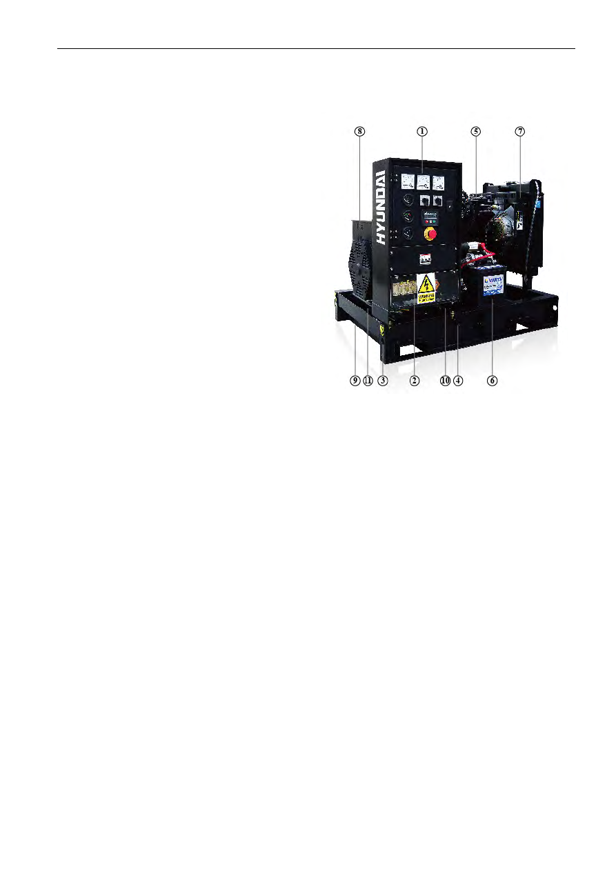
Generator Set Main Parts Specifications


NO            NAME 

1                CONTROL PANEL 

2                BUSBAR PANEL 

3                LIFTING LUG 

4                BASEFRAME FUEL TANK 

5                ENGINE 

6                BATTERY 

7                RADIATOR 

8                ALTERNATOR 

9                FUEL DRAIN OUTLET 

10       FUEL LEVEL SENSOR\ 

11              ABSORBER 


1.3


Diesel Engine 

According to different output power of the generator 
sets, and combine with the advantage of each model 
of diesel engine in a specific range of power output, 
HYUNDAI Power chooses the engines with first class 
performance  and  high  reliability.  And  furthermore, 
HYUNDAI  Power  pay  special  attention  to  the 


User manual 


technical  advantage  of  engines  in  the  aspects  of 
reducing  exhaust  gas,  decrease  fuel  consumption 
rate and good noise level control. 

1.4


Alternator 

All of the alternators chosen by HYUNDAI Power are 
single  bearing  self‐excitation  brushless  alternators 
with  the  attributes  of  international  top  brand.  By 
citing  Stamford  alternator  as  an  example,  we  can 
illustrate the features of our alternators as follows: 
Four  polar  brushless  self‐excitation,  single  bearing, 

insulation class is H and protection level is IP22. 

Stators are wound to 2/3 pitch, which can effectively 

eliminates triple and curbs waveform deformation of 
output  voltage.  When  in  parallel  with  the  mains  or 
other  generator  sets,  this  type  of  winding  can 
effectively  avoid  excessive  neutral  currents  and 
reduces inductive heat.
 

Before being assembled, rotors need to pass dynamic 

balance  testing.  The  improved  damper  reduces 
voltage deviation and heat under unstable load. 

The  exciter  rotor  output  is  fed  to  the  main  rotor 

through  a  three  phase  full  wave  bridge  rectifier,  the 
rectifier  is  protected  by  a  surge  suppressor  against 
surges  caused  by  short  circuit  or  out‐of‐phase 
paralleling.
 

◆ Automatic  voltage  regulator  has  the  feature  of 

automatic  load  curtailment  which  is  used  to  protect 
the  engine,  and  make  it  possible  to  add  full  load  to 
the  alternator  at  one  time.  Steady  state  voltage 
adjusting  rate  can  reach  ±1%  (under  certain 
requirements, steady state voltage adjusting rate can 
meet  ±0.5%).    If  PMG  system  is  chosen,  the  motor 
will  have  high  starting  capacity  and  the  ability  of 
interference  rejection  for  the  deformed  voltage 
waveform  fed  by  the  main  stator  generated  by 
non‐linear  load(such  as  silicon  control  DC  electric 
motor, UPS etc).
                                                                                                                                                                               

◆ Telephone  influence  factor  TIF<50,  telephone 

harmonic  wave  factor  THF<2%

the  brushless  style 

and  high  quality  AVR  ensures  low  interference  with 
Radio.        
 

1.5 

Cooling System 

The engine cooling system is water cooled. The water 
cooled system is comprised of a radiator a pusher fan 
and  thermostat.  The  alternator  has  its  own  internal 
fan to cool the alternator components.       

1.6


Electrical System 

The engine electrical system is 12 volt or 24 volts DC, 
negative  ground/earth.  This  system  includes  an 
electric  engine  starter,  a  battery  and  a  battery 
charging  alternator.  For  DC  12  volts  electrical  system 
one battery is given. For 24 volt system two lead‐acid 
batteries  are  given.  Other  types  of  batteries  may  be 

fitted if they were specified.                                                           

1.7


Coupling 

Engine and alternator are firmly joined by a coupling 
cone  that  guarantees  the proper  assembly  coaxiality 
Single‐support  machines  are  also  used  a  special 
flexible disk is used in place of a flexible coupling. 

1.8

 Fuel Tank and Base Frame 

The  engine  and  alternator  are  coupled  together  and 
mounted on a heavy duty steel base frame. This base 
frame  includes  a  fuel  tank  with  capacity  of 
approximately 8 hours operation under variable loads. 
The  tank  is  complete  with  filling  cap  and  fuel  level 
gauge and is connected by flexible joints to the intake 
piping  and  to  the  overflow  piping  containing  fuel 
from  the  injector  drain.  Big  capacity  generator's  fuel 
tank is separate from generator set. 

1.9


Control Panel 

All  models  of  HYUNDAI  Power  generator  sets  use 
high grade control panel. The core of control panel is 
an  imported  digital  diesel  engine  control  module, 
which  has  been  facilitated  with  more  complex 
functions  such  as  further  monitors,  demonstration, 
people‐module  dialogue,  distance  communication 
and protection etc.   
HYUNDAI  Power  generator  set  control  panel  use 
steel  plate  structure,  which  ensures  security  and 
reliability, and the surface of it has been treated with 
static  powder  painting.  The  outside  appearance  is 
beautiful.  Special  lock  has  been  used  to  fix  it.  It  has 
been designed for easy maintenance. 


1.10


Optional for Canopy Generator Set 

1.10.1 

External antifreeze adding hole


Our generator sets has been facilitated with external 
antifreeze  filling  hole.  When  user  intends  to  add 
antifreeze,  He  only  needs  to  open  the  antifreeze 
filling  hole  on  the  roof  of  canopy  and  the  radiator’s 
pressure  valve  cap  to  directly  add  antifreeze  to  the 
hole, and easily watch the anti‐freeze level. 


1.10.2

 Lubr

connect to 

Our  gener
lubricant  di
outside.  Th
humanized 
offers  mor
When  you 
change  it, 
lubricant dis

1.10.3


Impr

Our  canopy
easy  hoistin
generator  s
base  frame
have  design
forklift  ope
serves  the 
power  supp
frequently. 


1.11


Pre‐hea

Part) 

Our generat
water jacke
to ensure th
low  tempe

icant discha
 outside 

rator  sets 

ischarge  valv

his  lubricant

  design  fea

re  convenien

  want  to  di

  you  can  ea

scharge ball 

roved design

y  generator 

ng  and  tran

  set  is  facilita

.  For  the  sm

ned  hoisting

ening  in  the

  needs  of  cu

plier  but  nee


ater  for  gen

tor set has b

et. The purpo

hat the gene

rature  and 

arge hole wh

have  been 

ve  which  co

t  discharge 

ture  of  HYU

nt  operatio

ischarge  sur

sily  make  it

 valve.   

n for easy tr

  sets  have  b

nsportation. 

ated  with  lif

mall  power  g

g  lug  on  the 

e  base  fram

stomers  wh

ed  to  move 

nerator  set 

been facilitate

ose to instal

erator set can
  some  emerg

hich directly

  facilitated 

onnect  direc

  valve  is  an

UNDAI  Pow

n  for  the 

rplus  lubrica
t  by  openin

ransportatio

been  designe

  Standard  ca

fting  hole  o

enerator  set

  canopy  roo

me,  which  b

o  have  stati

  the  generato

  (Optional  S

ed with heat

l the pre‐hea

n be started 

gency  cases

  with 

ctly  to 
nother 

wer.  It 

users. 

ant  or 

g  the 


on


ed  for 

anopy 

on  the 

ts,  we 

of  and 

better 

ionary 

or  set 


  Spare 

ter for 

ater is 

 under 

s,  and 

al
da

1.

Ex
ge
ba
co
vi
su
ca
an
cu
p
co

lso  it  can  p

amaged by c

.11


Others 

xcept for ab
enerator  set

attery  for 

orrugated  p

ibration  redu

uch  as  base 

anopy, the lu

nti‐freeze an

ustomer  etc

lease  refer 

ontract. 

revent  the 

 cold winter w


bove mention

t  has  other 

start  moto

pipe,  exhau

uction  unit,  a

  frame  type

ubricant used

nd other part

c.    For  the

  to  genera

  generator  s
weather! 

ned compon

  main  compo

r,  battery 

ust  elbow, 

  and  other  al

e  fuel  tank, 

d by the eng

ts specially re

e  specific  a
ator  set  pa

User man

ets  from  be


nents, the die

onents  such

cable,  silen

  high‐efficie

lternative  pa

  daily  fuel  ta

ine at first ti

equested by 

ccessory  pa

acking  list 

nual 

eing 

esel 

  as: 
cer, 

ency 

arts, 

ank, 

me, 

 the 

arts, 

and 


User manual 


2


Installation


2.1


General Outline 

Correct  installation  of  generator  set  is  the 
precondition which ensure the normal working status 
of the generator set. The working room for generator 
set  shall  be  designed  specifically  to  meet  the 
expected functions and maintenance operations, and 
at the same time the design of generator set working 
room  shall  conform  to  local  government’s  laws  and 
regulations  on  architecture,  fire  protection  laws  and 
other applicable regulations. 

2.2 

Transportation


During  the  period  of  shipment,  protection  shall  be 
made  for  the  generator  set.  In  addition,  the 
generator  set  shall  be  tightly  secured  in  the  loading 
truck  so  that  to  avoid  any  vibration  during  shipment 
which  will  cause  the  generator  set’s  components 
loosen  and  even  damaged.  During  the  process  of 
shipment  of  generator  set,  no  people  or  other 
material  is  allowed  to  place  above  the generator  set 
so  that  to  avoid  damage  to  generator  set  caused  by 
weight. 
When  loading  or  unloading  the  generator  set  to  the 
truck, forklift or hoisting device shall be used to avoid 
the generator set become tilted or fell to the ground, 
which causes damage. 
Lifting  holes  have  been  designed  on  the  common 
base  frame  of  our  generator  sets.  Some  of  the 
specifically  designed  generator  sets  has  been 
facilitated  with  lifting  holes  on  the  roof  and  forklift 
openings on the base frame etc. Users can transport 
the generator set according to the guidance specified 
on  the  specific  labels  sticked  on  the  generator  set. 
Please do not use the lifting lugs on the engine or on 
the alternator to hoist the whole generator set. 

2.3 

Design for Foundation 

The foundation which used to install and fix the diesel 
generator  set  is  very  important,  it  must  conform  to 
the following requirement: 
Have enough hardness and stability, so that to avoid 

deformation,  which  will  affect  the  concentricity  of 
diesel  engine  and  alternator  and  other  accessory 
parts.
 

To support the weight of the whole generator set and 

to absorb the dynamic impact caused by unbalanced 
force and vibration during engine’s running period. 

Generator set’s foundation is not allowed to connect 

to other architecture’s foundation. 

◆ The  width  and  depth  of  foundation  shall  meet 

requirement. 

Ensure foundation’s levelness and smoothness. 
If possible, waste discharge sink can be sued so that 

the  waste  oil  can  be  discharged  in  a  timely  manner. 
Cable channel for generator power output cable need 
to be reserved. 

Normally, concrete foundation is reliable, simple and 

preferable.  When  pouring  the  concrete  foundation, 
please make sure the surface of concrete is flat, and 
no  scratch  is  allowed.  Gradienter  or  similar 
instruments  need  to  be  used  during  installation  of 
generator set and its exhaust system. 

The  design  of  foundation  can  refer  to  following 
calculation  formula:  (below  is  the  diagram  for  diesel 
generator set foundation) 
1. Generator dimension length × width: L1×W1 
2. Foundation dimension length × width: L2×W2 
    L2 =L1+400 (mm) 
    W2 =W1+400 (mm) 
3. B=2×M/ (L2×W2×D) 
    B: Thickness of foundation         

M: Generator set weight 

    L2: Length of foundation           

W2: Width of foundation 

    D: Density of Concrete (refer to 2322kg/m3) 
(Foundation drawing Refer to APPENDIX A ) 


2.4


Design for Generator Set Working Room 

The installation of generator set shall be designed, so 
that  to  meet  the  demand  of  planned  operation  and 
maintenance. The complete installation shall conform 
to  local  architecture  laws,  fire  protection  laws  and 
other  applicable  regulations.  Except  the  above 
matters,  there  are  other  matters  needs  your 
attention as follows: 
Ensure diesel engine generator set working room is 

furnished with rainproof, sunscreen, and windproof. 

Ensure diesel engine generator set working room has 

good  ventilation  and  good  exhaust  system,  and  the 
area for ventilation is sufficient, and at the same time 
use  pipes  to  let  out  the  hot  air  generated  from  the 
radiator and prevent the hot air from returning. 

Ensure the waste gas generated during generator set 

running  period  can  be  discharged  to  outside  timely, 
and try your best to reduce the adverse effect caused 
to  environment.  The  silencer  and  exhaust  pipe  shall 
be  supported  by  the  roof,  the  supporter  shall  allow 
the  exhaust  pipe  to  expand.  It  is  not  permitted  to 
install  the  exhaust  system  directly  on  the  generator 
set. 

◆ Enough  space  shall  be  reserved  for  the  diesel 

generator  set  for  convenience  of  cooling,  operation 
and maintenance etc. Generally speaking, no foreign 
material  is  allowed  to  be  placed  within  the  area  of 


Content   ..   1  2  3   ..