YANMAR Diesel Engine 1GM, 2GM, 3GMD, 3HM. Manual - part 6
 

  Index      Engines     YANMAR Diesel Engine 1GM, 2GM, 3GMD, 3HM - service manual


Search            


Content   ..  4  5  6  7   ..


YANMAR Diesel Engine 1GM, 2GM, 3GMD, 3HM. Manual - part 6


FOR 2GM, 3GMD, 3HM
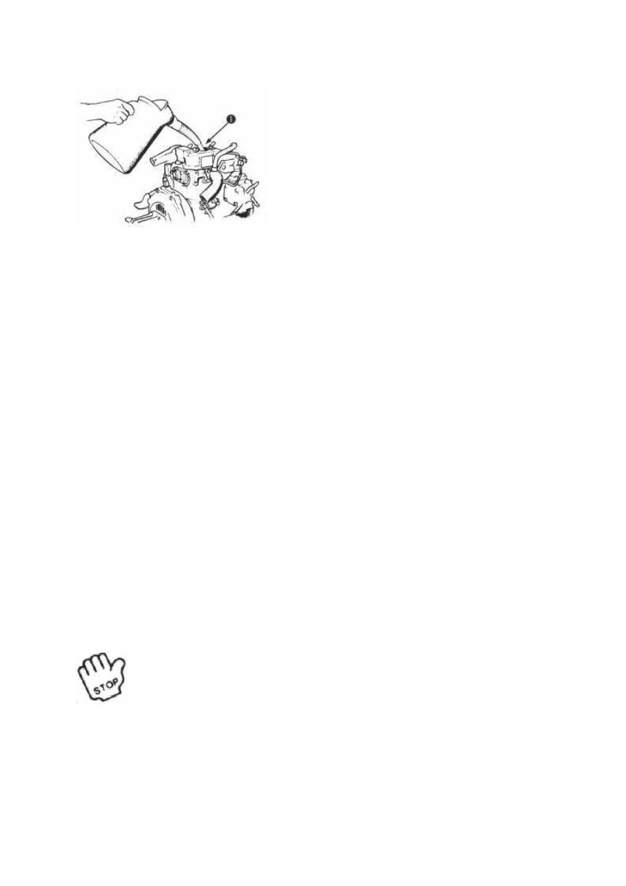
1. Oil Supply Port

1-b)
Check the amount of lobe oil by inserting the dipstick as far as possible. The oil level should
correspond to the upper mark on the dipstick.

Volume of the tube oil corresponding to the upper mark on the dipstick (with an installation
angle of 8°)

Engine crankcase
1GM

2GM

3GMD

3HM

1.3 L

2.0 L

2.7 L

5.5 L

Note.

When running the engine for the first time, the tube oil flows to the piping thus reducing the
amount of oil in the crankcase. After running the engine for several minutes, stop it for 2-3
minutes.
Recheck the oil level.

2) Lube oil to the reduction and reversing gear case
For the checking of the amount of tube oil to the reduction and reversing gear case, check
with screwing the dipstick.

Volume of tube oil corresponding to the upper mark on the dipstick (with an installation
angle of 8°)

Important!

The tube oil for reduction and reversing gear is different from engine tube
oil for 3GMD and 3HM. Supply correct tube oil.

1. Dipstick
2. Empty
3. Full

1. Oil Supply Port

1. Oil Gauge Rod
2. Lower Limit
3. Upper Limit

[6-3.] Air bleeding in the fuel system

See section [9.1] Fuel oil system - 2) Air bleeding in the fuel system.

[6-4.] External Inspection

1) Thoroughly check for loose nuts and bolts.

2) Check the area around the revolving parts and the upper part of the engine where jigs and
other tools may have been placed and forgotten. In general, be sure the engine room is always
kept shipshape.

[6-5.] Remote control device check

1) Pull out the engine warm up knob, change the control
lever from the "speed decrease" position to the "speed
increase" position. Check the slippage of the position on the
bridge and in the engine room, and adjust as necessary.

Note
The knob for engine warm up can only be operated when the
control lever is placed in the "Neutral" position.

2) Push the engine warm up knob back in, move the control
lever through "Ahead", "Neutral", and "Astern", check the
position of slip page in the engine room, and make
adjustments as necessary.

See [9.7] Remote control cable adjustment section for

the adjustment procedure.

1. Control lever
2. Engine warm-up knob

[6-6.] Check of instrument panel alarm system

Turn on the battery switch. Then place the key in the "ON" position and check the condition
of the lamps on the panel (with the engine stopped).

1) Lube oil warning lamp. Should be lit.

A-TYPE

B-TYPE

1. C.W. Temp
2. Charge
3. L.O. Press
4. Push Button
5. Warning buzzer
6. Key switch

2) Cooling water temperature warning lamp. Should be out. (for small type panel; A-type
only) For the large type panel (B-type), raise the CHECK switch "ON" to see if the cooling
water temperature warning lamp lights.

3) Charging warning lamp. Should be lit.

4) The warning buzzer. Should sound.

Note
All the above alarm signs will continue until pushing the starting button or turning the key
off.


Content   ..  4  5  6  7   ..