YANMAR Diesel Engine 1GM, 2GM, 3GMD, 3HM. Manual - part 4
 

  Index      Engines     YANMAR Diesel Engine 1GM, 2GM, 3GMD, 3HM - service manual


Search            


Content   ..  2  3  4  5   ..


YANMAR Diesel Engine 1GM, 2GM, 3GMD, 3HM. Manual - part 4


Note

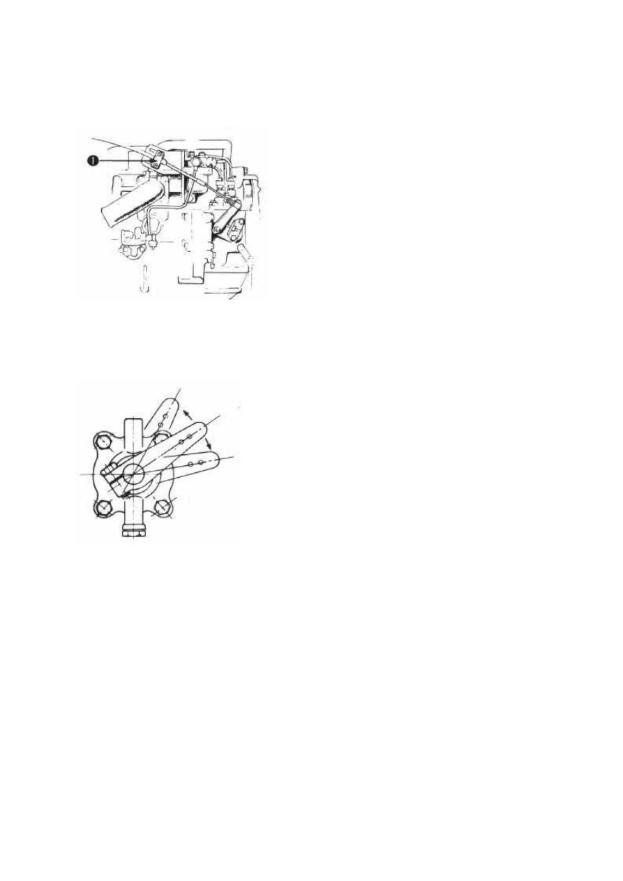
1) Fix the wire to the cable clamp of the F.O. filter side.

2) Cable connector has M5 thread.

2-b)
After completing of wiring, check the following
points:

2-b)-1.
That the remote control lever and speed control lever
can be moved smoothly through the whole stroke.

2-b)-2
That the idle speed adjuster regulates the speed to
850-900 rpm, after all preparations for starting the
engine have been completed.

1. Cable clamp

3) Clutch Control

3-a)
Cone Clutch (for 1GM, 2GM, 3GMD)

3-a)-1.
Remove the spring joint from the operation lever.

3-a)-2.
With the spring joint disconnected from the operation lever,
move the operation lever forward and reverse, to make sure
that the strokes from the neutral position are the same.

3-a)-3.
Attach the spring joint to the operation lever 60mm from the shaft lever center.
The stroke from the neutral position moves through a distance of 24.4 to 35.Ohm. When the
spring joint is attached to the hole 52mm from the center of the shift lever, these strokes must
be 21.1-30.Ohm.

Note

The operation lever may not move smoothly when there is no lubrication oil in the clutch
case.

1. Remote Control Cable
2. M5 Thread
3. Operation Lever
4. Shaft
5. Clutch Case side cover
6. Spring joint

3-a)-4
Move the remote control lever to the forward
position, and make sure that the M5 thread of the
spring joint reaches to the inside of the joint. 
In this position, the output shaft (propeller shaft) of
the clutch should rotate clockwise as viewed from
the stern.

3-a)-5.
Move the remote control lever to the reverse position,
and make sure that the M5 thread of the spring joint
reaches the outside of the joint. In this position, the
output shaft (propeller shaft) of the clutch should rotate
counter-clockwise as viewed from the stern.

3-a)-6.
Adjust the M5 thread depth so that the value of A, and 16 are nearly the same.

3-a)-7.
Make sure that the angle made between the spring joint
and the clutch control lever forms 90 degrees.

3-b)
Kanzaki-Hurth clutch (for 3GMD and 3HM)
To connect the cable, the operating cable must
be positioned at right angles to the shift lever
when the shift lever is in the neutral position.
The shift play, measured at the pivot point of
the shift lever, must be at least 35mm to each
side (reverse and forward) from the neutral
position. A greater shift play has no adverse
effect on the marine gearbox. After connecting
the linkage, confirm that the remote control
and the shift lever on the marine gearbox work
properly. A typical linkage arrangement is
illustrated in the figure below.

1. Astern

4. Propeller side

2. Neutral

5. Engine Side

3. Ahead

Note

Since the cable stroke may be insufficient, two holes are
drilled in the shift lever.
When the cable is attached to the hole 60mm from the
center of the rotation of the shift lever, the strokes from
the center to the forward and reverse sides must be
35mm. When the cable is attached to the hole 52mm
from the rotation of the shift lever, these strokes must be
30mm.

4) Engine stop remote control Connect the engine stop
remote control cable  as in the illustration, after
completing 
the wiring check that the engine stop lever
can be moved smoothly through the whole stroke.

1. Clamp
2. Engine Stop lever
3. Engine stop remote control cable

[3-7.] Recommended battery capacity

Use sufficient capacity of battery.

1GM, 2GM, 3GMD

-

12V - 70AH (Mini)

3HM

-

12V - 100AH (Mini)


Content   ..  2  3  4  5   ..