Technology of watch production - part 99
 

  Index      Books     Technology of watch production (Tarasov) 1964 year


Search            


Content   ..  97  98  99  100   ..


Technology of watch production - part 99


CD 

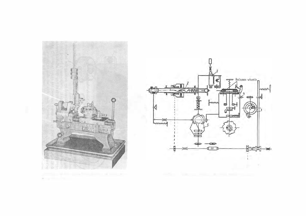
FIGURE 34.  PR-151  automatic  machine for mounting screws 
on the  balance wheel 

�� 

FIGURE 35.  Kinematic diagram of the PR-151  automatic machine 

The  magazine  must accurately  pos ition  the  s c rew  relative  to  the  machine 

spindle  coll e t .   The  turret  head,  in turn,  must  accurately  cente r  the  balance 

hole  with respect to  the  s c rew  in  the  coll e t .  

The  magazine  ( 3 ) ,   is  displaced  vertically between  guideposts b y  means 

of a  lever  ,;_nd  cam  (see  Figure 

3 5 ) .   It is  lowered  when  the  turret  head  is 

withdrawn,  and  the  casette  with  the  s c rew 

is  fed  to  the  coll et.  It  is  lifte d  when  the 
turret  head  approaches,  making  it  pos sible 
for the collet to rotate the s c rew.  Spindle 

(2 ) 

has  a  friction  coupling  which prevents 

breakage  of  the  s c rew in  cases  of tight 
threads .  The  cam shaft 

( 5 )  mounts  cams 

which  c ontrol  the m otions  of the tu rret head, 
the  magazine  m echanism ,   and  the  closing 

of  the c ollet.  The  machine  handles  10  bal -
ances  in 

2  minute s .   Screws  are  placed in 

FIGURE  36.  Double roller w ith impulse pin 

the  cas ette  manually,  and  each  s c rew  thread 
is  inspected  during loading.  The  machine 

is  d riven by  an  electric  moto r .   A fter the 

sc rews  have  been  assembled,  the  balance  is  directed  to  the  electroplating 

shops  for  gold-plating .  

The  balance  wheel  i s  mounted  on its  staff i n  the  same  way a s  wheels  are 

m ounted  on pinions 

(D-246 pedal - operated press ) .   The  balance  staff i s  in­

s erted  into  the  housing  of the lower die  with its  shoulder  s erving as  s upport­
ing surfa c e .  

FIGURE 37.  Device  for static posing o f  the balance-wheel subassembly 

A fter the  balance  wheel  has  been placed p roperly  on  the  chamfer  of  the 

corresponding  shoulder,  the  press  is  actuate d .  

Mounting  of  the  wheel  on  the  staff  is  followed b y  setting  the  balance  in 

the  fac e  plane  which  is perfo rm ed in two stage s :   preliminary (using pincers ), 

and final  (P - 3 2  ins trument )  (F igure 

1 9 ) .  The face run-out whos e permissible 

value  is  0 . 02 mm  is  checked  by the  same  instrum ent  simultaneously with the 
setting  ope rations . 

3

94 

The  double  roll er,  with  the  impulse  pin  previouslj  pres s e d   into  it  (Fig­

ure  36 ) ,   is  set on the staff  on a  D - 2 4 6   pedal - op e rated  press .  Shellack is 
melted into  the j oint  afte r the pi.n  is  pres s e d  into the double  roll e r  in  order 
to  increase the tightness  of the ass embly.  The  pos ition of the  impulse  pin 

relative  to  the  recess  and  the  central  hole  of the  roll e r  is  inspected  in  a 

profile  projector,  and  the  tightness  of  its  m ounting  is  checked in a  special 
devic e .  

The  balance  wheel  i s  pos itioned,  using pincers,  i n  a die i n  the lower  shoe 

of the  pres s .   The  roller is  positioned ,   again  using pincers ,  on the  balance 
staff  and  is  pushed  against the  shoulder of  the  balance  staff  by  means  of a 
punch  m ounted  in  the  press  spindle  (see  Figure  3 2 ,   d ) .  

The  run - out  o f  the  safety  (guard )  surface  ( 0 . 0 1 5  mm  allowable )   i s  in· 

spected using a  dial gage  (see  Figure  2 0 ) . 

The  unbalance  in  the  balance  wheel,  due  to  inaccuracies  in  the  manu­

facture  of parts  and  in their ass embly,  is,  to  a  ce rtain  extent,  corrected by 

statically  "poising" the  subas s embly  (Figure  37 ).  The balanc e - staff  journals 
are  placed on  knife  e dges  made  of  ruby  (see  Figure  3 2 ,   e )  and  an  oscillating 
motion  is  manually  imparted  to  the  wheel .  If  the  unbalance  of the  wheel  is 
conside rable ,   it will stop  rapidly with  the  heavy  part  coming to  rest  at  the 

bottom .  The  balance  is  then  removed  from  the  knife  edge s ,   and  the  weight 
of the  s c rews  in the heavie r  part is  reduced  (or the  weight  of the  s c rews 

on the  oppos ite  s ide  increas e d )   by  removing  or adding adjusting washers . 
The  operation  is  then  repeated ,   until  the  balance  wheel  is  clearly  in  the 
indifferent  state  of  equilibrium .  Static  poising is  followed by  fitting  the 
hairspring,  and  by  dynamic  balancing  in  the  P- 1 2   instrum ent. 

A s s embly  of the  Hairspring and Collet 

A  properly  stabilized hairspring has the shape  of an A rrhim edean  spiral . 

The  inside  end  of  the  hairspring  (2 )  is  fastened  to  a  brass  bushing  ( 1 )  (Fig­

ure  38,  a ),  called the  c ollet.  Pince rs  are used to  introduce  the end of  the 

FIGURE 38.  Setting the hairspring in the collet 
and stud: 

a-setting the inside end in the collet;  b-setting 

the  outer coil in the stud. 

3 9 5  

FIGURE 3 9 .   Shape of the inner 
terminal curve 

hairspring into  the  late ral  hole  in  the  collet and  it  is  locked in place  by  the 
tapered pin  (3 ).  The  hairspring  is  aligned  (in the  plane )  and  its  terminal 

curve is s imultaneously bent .   The  inner  term inal  curve is so  made  that  its 

initial  part  does  not  come  in contact with  the  collet when the  hairspring is 
twisted  3 3 0°,  while,  at  the  same  tim e ,   its  dis tance  from  the  collet does  not 

exceed  a  value e qual  to  the  spiral pitch  (F igure  3 9 ) .  

The  outer  end  o f  the  hairspring is fixed t o  the  stud . 

A s s embly  of  the  Balance  and  Hairspring 

The  ass embly  of  the  b a l a n c e - h a i r s p r i n g   system  involves  mount­

ing the  hairspring with  collet  on  the  balance  staff,  establishing the  system 
period,  fastening the  outer  end  of the hairspring to  the  stud,  shaping the 
outer  terminal  curve,  and  dynamical ly balancing the  entire  syste m .  

The  D - 2 4 6  press ,  which was  used f o r  the  double  roller,  i s  als o  u s e d  for 

mounting the  hairspring and  collet  on  the balance  staff  (Figure  40,  a  and b ) .  
Hairspring and  balance  are  simultaneously aligned i n  the  face  plane . 

FIGURE 40.  Balance-hairspring assembly : 

a-balance with staff and double roller;  b-hairspring with collet. 

The  oscillation  pe riod  of the  system  is  established by  the  P- 1 2  instru­

ment  (see  th�  section  on  "Watch adjustm ent " ) .   The  period  of  os cillations 
is  marked  on  diagram  paper and  compared with the  standard  period for  the 
instrument.  The  pe riod  of  the  system  being  tested  is  adjusted by  varying 
the  hairspring  length  (the  hairspring  has  a  rese rve  of  1 . 5  to  2  oute r  turn s ), 

until  it  coincides  with  that  of  the  standar d .   The  system  is  vibrated  in  a 

horizontal  pos ition . 

After  the  hairspring  has  been brought  to  size,  the  outer  end  of  the  hai r ­

spring i s  fa stened  to  the  stud i n  the  s a m e  P- 1 2  instrument  ( s e e  Figure  3 8 , b ) .  
The  end  (2 )  o f  the  hairspring is  introduc ed into  the  hole  i n  s tud  ( 1 )  and  is 
fastened  to  it  by  the  tapered pin  (3 )

Devices  which  do  not  require  removal  of  the  hairspring from  the  balance 

staff  are  used to  shape  the  oute r  terminal  curve .  The  shaping  is perform ed 

3 9 6  


Content   ..  97  98  99  100   ..