Technology of watch production - part 95
 

  Index      Books     Technology of watch production (Tarasov) 1964 year


Search            


Content   ..  93  94  95  96   ..


Technology of watch production - part 95


the  coaxiality  of  corresponding holes  in the  plate  and  b ridge .  The  pins 

must  therefore  be fitted without slant,  and  the  bridges  are  assembled, again 

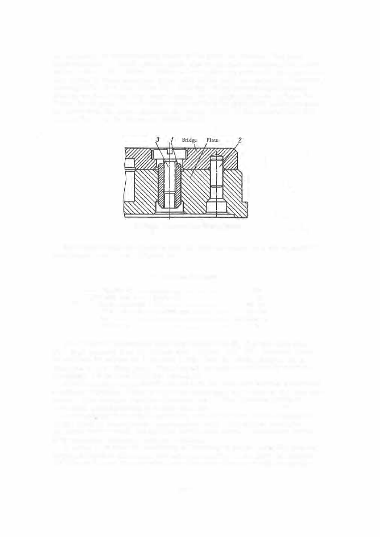
without  slant.  The  bridge  is  fastened to  the  plate  by  screw ( 3 )  and  sleeve ( 1  ) .  

The  sleeve  i s  fitted  into  plate  holes  with  0 . 0 1 0- 0 . 0 1 5  mm negative  allowance ,  

corresponding t o  a  light  drive fit.  This  type  of bridge-fastening arrange ­

m ent  is  us ed in  order to  prevent  damage  to  the  expensive plate  in case  the 

thread  is  s tripped.  The  sleeve  is  press e d  into  the  plate  with  sufficient force 

to  ensure  that the s crew can hold the bridge tightly  to the plate  without dis ­

turbing  the  fit  of  the  sleeve  or  displacing it. 

FIGURE 

8.  Bridge-to-plate fastening system 

Pins  and  sleeves  are  p ressed into  the  plate by m eans  of  a  die  on  an 8 - 1 0  

bench-type  power p ress  (Figure  9 ). 

Technical data,  S-10 press 

Capacity,  kg 

• 

• 

• 

• 

• 

.  .  .  .  .  .  .  .  .  . 

500 

Stroke,  mm 

• 

• 

• 

• 

• 

•  • 

• 

• 

• 

• 

• 

• 

15 

Strokes per minute 

• 

• 

• 

• 

• 

• 

• 

• 

• 

• 

• 

.  . 

30o-500 

Distance  from  ram to press bed,  mm 

• 

.  .  .  .  . 

4o-175 

Dimensions,  mm 

• 

• 

• 

• 

• 

• 

• 

.  .  .  .  250 x 280x 450 

Weight,  kg  . 

• 

• 

• 

•  • 

• 

• 

• 

• 

• 

• 

.  .  .  .  .  . 

30 

The  "Pobeda "  wristwatch plate  has  s ix  sleeves  (81 -8R )  and  eight pins 

(87 - 81 5)  pre ssed  into  its  bridge  side  (Figure  1 0) .  The  pres sing  force 
is  checked  by  means  of  a  special  device  and  the  fitting  height,  by  a 

dial  gage  on  a  vertical post.  Both inspections  are  carried  out  by random 

sampling:  5 %  of each batch are  examined. 

Jewel bearings are pressed into  holes  in the plate  s nd  bridges  which have 

a  negative  allowance  between  0 . 0 1 0  and  0 . 0 3 0 mm,  depending on the hole  dia­

m eter .  The  average negative  allowance  for 

1.2 

mm  diameter jewels  is 

0 . 0 1 5  mm,  corresponding to  a light drive fit. 

Jewel setting  is  a  crucial  operation,  and the fits have been established 

on the  basis  of considerable  experimental  work.  The  stones  used  are 

synthetic  rubies  which,  being more  brittle  than m etals ,   s ometimes  break 

if the  negative  allowance  exceeds  0 . 03 0 mm .  

In  order to  reduce  the possibility o f  b reaking in press  ass embly with the 

required negative  allowance,  the  entering chamfer of the  jewel is  rounded 

off  (Figure  1 1 )  and the pressing force  therefore  increases  only  gradually. 

3 7 7  

The  jewel  must tightly  adhere  to  the  hole  wall  on  its  entire  cylindrical 

surface  (Figure  12 ). 

FIGURE 9 .   S-10 

press 

FIGURE  10. 

Plate with sleeves  and  pins pressed  in 

FIGURE 11 . 

Through-hole  jewel 

FIGURE 12 . 

Jewel setting  in plate  and bridges: 

a -correct;  b-incorrect. 

Jewels  are press ed  into  their  respective  s eats  on S- 1 9 5  pre ss es  (Fig­

ure  1 3 ).  The press  is  driven by a  0 . 0 7  kw,  3000 rpm  electric  motor.  The 

m otor drives shaft (4 )  through the worm and wheel  (2,  3) and key  ( 5 )   (Fig­

ure  1 4 ).  The flat  cam  (6 )  on shaft  (4) acts  on lever ( 7 )  which communicates 

a  downward m otion  to  the  ram  ( 1  )

Ram  and lever  are  returned to  their 

initial position by a  spring. 

The upper part of the  ram  has  a  m icrometric  s cale  with  divisions  of 

0 . 0 05 mm.  Pins  and sleeves  that  require  very light  assembly forces can 

be  fitted  on this  pre s s .  

Pressing-in  is followed b y  a n  inspection o f  jewel  intactnes s   (no fractureE 

or cracks  are  allowed ),  depth and  tightness of the  fit,  and alignment. 

All plate and bridge  jewels  are  inspected,  after their s etting,  using a 

magnifying  glass  ( 5X).  A  microscope  of  1 6X to  32X  magnification is used 

in dubious  cases . 

1174 

3 7 8  

The  depth  of  the  fit  is  inspected using a  dial  gage  or  a  watch  micrometer, 

m ounted  on a  vertical post. 

Fit tightness is  checked by m eans  of special  devic e s .  

FIGURE 

1 3 .   S-195 

press 

FIGURE 

14. 

Kinematic  diagram 

of 

the 

S-195 

press 

3 7 9  

Wheel -pinion  A s s embly 

A  characteristic  feature  of the  assembled wheel  and pinion is the relative ­

ly  s mall  wheel  thickness  compared  with  the  fitting- hole  diameter  (Figure 1 5 ) .  

This  results  from  the  fact that  the  moments  transmitted in  watch movements 

are  very small  and  the  wheels  are  therefore made as light as poss ible  in 

o rder to  m inimize  friction losses . 

FIGURE  15. 

Center wheel 

and pinion 

The  tightness  of  the  wheel fit  on  the  pinion in  the  gear-pair subassemblies 

must be such that the  wheel  will  not slip  on its  shoulder,  and that the  radial 

and face  run- outs  will  not exceed  the  tole rances  specified. 

The third and  fourth  wheel s ,   which transmit  very small  moments ,  are 

s et  on the  pinion with a  negative allowance of 0 . 0 - 0 . 01 m m .   Large r  nega­

tive allowance s  increases the  radial  and  face  run- out s .  

The  c enter  wheel ,  which transmits  a  larger  moment than that trans ­

mitted by  the  third  and  fourth wheels,  is  s taked to  the  pinion shoulder  (in 

addition to the  negative  allowance ),  although the  s taking increases  the  radial 

and face run -out for the  wheel  (see  Table  1 ) .   A s  the  escape wheel  works  in 

impact it  is  also  staked  even though it transmits  small  moments . 

TABLE  1 

Permissible  radial and  face  run- out for  "Pobeda" wristw atches 

Subassembly 

Center wheel. 

. . . . . . . . . . • . . . .  

Third  and  fourth  wheels . . . . . . . .  

Escape  wheel.  . . . . . . . . . . . . . .  

3 80 

R un- out.  mm 

R adial 

Up to 

0.02 
0 . 015 

0 . 01 0  

Face 

Up  to 

0.03 
0.02 
0.02 


Content   ..  93  94  95  96   ..