Technology of watch production - part 78
 

  Index      Books     Technology of watch production (Tarasov) 1964 year


Search            


Content   ..  76  77  78  79   ..


Technology of watch production - part 78


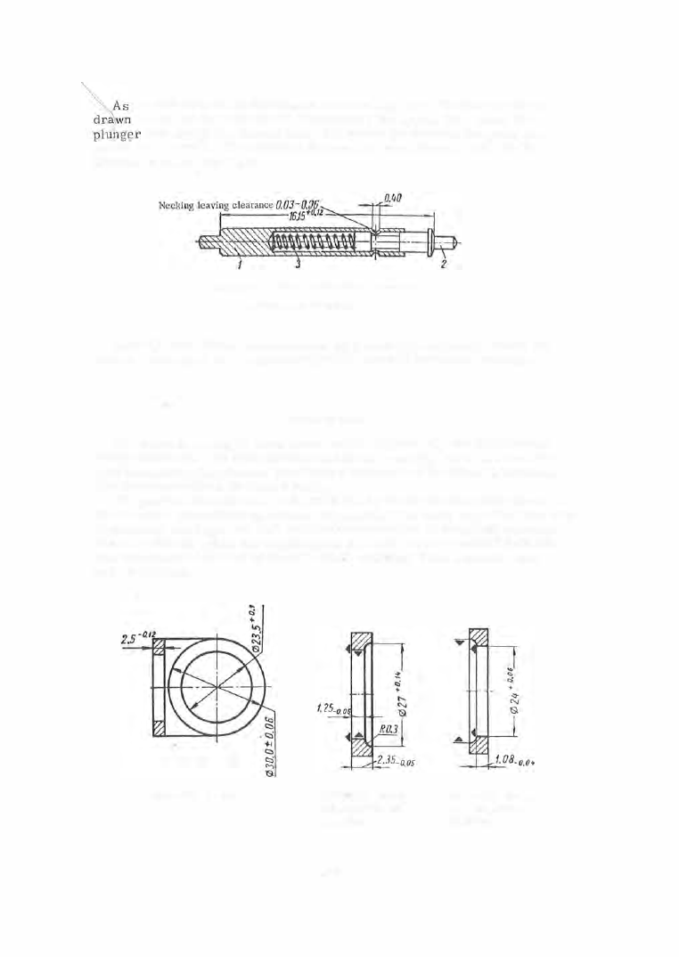
the b a r  body  ( 1 ) i s  introduced into  one  lug hole,  the  plunger  (2 )  is 

to  the  left by pince rs  and  compresses  the  spring  ( 3  ).  When  the 

end  enters  the  s econd  hole,  the  spring  ( 3 )  presses  the plunger a ­

gainst  the  lug wall .  The  distance between the  shoulders  i s  equal t o  the 

distance between the  lugs . 

FIGURE  22.  Strap  bar  of the " Pobeda"  watch case : 

1 -body ;  2-plunger;  3-spring. 

Parts  ( 1 )  and  (2 )  a re  manufactured  on Swis s - type  automatic  s c rew ma­

chine s ,   while  part  ( 3 )  is manufactured on a  special  automatic  machine . 

THE  CASE  BEZEL 

The bezel  is  a  ring  of  weak  cross  section  (Figure  2 ),  and  is  the refore 

easily deformed.  Its configuration and  its  low rigidity led to the  use of a 
split manufacturing p rocess  (involving a  sequence  of  roughing operations ). 

The main ope rations  are listed below. 

The part is  blanked  from  strip  material by an Sh- 04  compound die  on a 

2 0 - ton c rank press (first ope ration,  Figure 2 3 ).  The  strip layout is a  two - row 

chessboard  arrangement  and  the blank deformation in the  plane  must  not 
exceed  0 . 05 m m ,   while the ellipticity of the  hole  must  not  exceed 0 . 05 m m .  

The blanking i s  followed b y  stress  relief,  was hing,  burr removal,  and 

repeat  washing. 

FIGURE 23.  Bezel blank 

FIGURE 24.  Facing 

and boring (second 

operation) 

309 

FIGURE 25.  Facing 

and boring (third 
operation) 

The  blank  is  gripped in a  chuck on  a  special  lathe  (Figure  24 ),  one  of  its 

faces  is  faced,  and a  2 7  mm  diameter  recess  is  machined  (second operation ) .  

The  opposite side is  then faced,  and  a  24 mm hole  is  bored  (Figure  2 5 )   on 

a  special  machine  (third  operation).  The blank is then positioned accord­
ing to the bored hole and its adjacent face in a  special  lath e .   The outer 

diameter of  the  blank,  its  opposite face  and  the  fitting s houlder are  then 

turned  (Figure  2 6 )  (fourth ope ration ) .   The  ovality  of the  28 mm  diameter 

fitting shoulder must not exceed  0 . 02 mm,  according to the technical  spe­

cifications  for case assembly. 

FIGURE 26.  Turning the 
outside diameter (fourth 

operation) 

Section AA 

.. 

FIGURE 27.  Milling a flat (fifth operation) 

A n  inclined  flat  is  then m illed in a  horizontal  milling machine  (Figure  2 7 )  

(fifth  operation).  This  is  followed by the  machining of the  recesses for the 

c rystal  and  dial  and by  chamfering (Figure  2 8 )  on a  special  lathe  (s ixth oper­
ation ) .  

The  crystal  and dial  recesses  must b e  concentric  relative t o  the  fitting 

shoulder  for  the  case  middle,  and  the  run- out  of one bore  relative  to the 

other  one  must  not exceed  0 . 03 m m .   The bezel is then positioned by the 

recess,  (Figure  2 9 )  on a  special  lathe  and  the  tapered edge  is  turned  (sev­

enth  operation ) .   The  outer surface  of  the  be zel  is  then polished  and  buffed 

(prior to  electroplating)  (Figure  3 0 )  on the  S-42 polishing machine  (eighth 

operation ) .  

FIGURE 2 8 .   Boring for the 
crystal and the dial (sixth 
operation) 

FIGURE 29.  Taper 
turning (seventh 
operation) 

3 1 0 

FIGURE  30.  Out­

side-surface polish­

ing (eighth operation) 

The  fitting  dimensions  of  the  bezel shoulder and  the  bore  of  the  middle 

are machined  to  a  toleranc e  of  0 . 04 5  m m .   The  negative  allowance  in  the 

bezel-middle  assembly  can  therefore  vary  within a  range  of  0 . 09 mm,  while 
the  value  allowed by the  specifications is  only  0 . 0 5  m m .   The  middles  and 

b ezels  are  accordingly  s orted into  two  groupa . 

The  number  of  bezels blanked from  strip material  in  the  form  of  rings 

represents  only  3  to  5 %  of the  bezel-production program .  Most of the  be zel 

blanks have  the  shape  of o val  rings  (Figure  2 0 )  or disks  obtained as  scrap 

in the  blanking of the  case middle  (Figure  3 1  ).  A  hole is  pierced in the 

4 mm  thick,  2 3 . 5  mm  diameter  disk,  and it is  then  stress - relieved  and  twice 

e xpanded  in a  die,  after  which its  shape  and  dimensions  are  identical  with 

those of the  bezel blanked  from  strip.  Expanding  reduces both  the  width 

and  the  thickness  of the  ring walls .  The  primary blank  dimensions  are  de­

termined experimentally. 

o o o 

FIGURE 31.  Bezel blank obtained from middle-blanking scrap 

The bezel is  subjected to  electroplating,  afte r  which  it  is  assembled 

with the  crystal .  The  crystal  is  blanked from  a  plexiglass  strip  0. 8 - 1 mm 

thick,  turned and chamfered.  The crystal  is  then  given a  convex shape in 

an electrically  heated die  ( 1 1 0- 1 2 0°C ) and  pressed into the bezel by means 

of a  pres s .  

THE  CASE  BACK 

The  case back has  a  thickened  flange,  necessary  to  ensure  its  tight 

coupling with the  case  middle  (see Figure  2 ).  The  back  snaps  onto the  mid­

dle due to  elastic  deformation. 

Backs are blanked  from  strip  material and s imultaneously  drawn.  The 

flange  profile  is  then formed according to  the  fitting dimens ions,  and the 

inner  and  outer  s urfaces  are polished and buffed. 

The part (Figure  3 2 )  is  blanked by a  compound  die  in a  crank press 

(first operation).  The  strip  layout is  a  double - row chessboard  arrange ­

ment  and  the  final  dimensions  of  the  drawing punch  and  die are  established 

during the testing of the die . 

The back flange  is  formed in  two  upsetting operations  (Figures  3 3  and 

34 )  in toggle-lever presses of 1 0 0  to 1 2 5  ton capacity  (second  and third  oper­

ations ) .   The S- 8 1A  two- spindle  s emiautomatic  machine (fourth  operation) is 

used to face the  flange and to machine  the  2 7 .46 mm diameter lip (Figure 3 5  ). 

3 1 1  

A  flat  is  milled on the  back  (Figure  3 6 )  using a  horizontal  milling ma­

chine  (fifth operation) and  an angle  milling cutter  with the back  held  in  a 
fixture .  Seve ral  plants  have  recently begun  to  grind  this  flat  in  a  special 

automatic  machine ,  whose production 

FIGURE 32 .  Back blank 

rate  is  five  times that  of the  milling 

machine . 

A  design  is  chased on the  inside  of 

the  back  (sixth  operation )  (Figure  3 7 )  
on a  special  two - spindle  s emiautomatic 

machine  (Figure  38 ).  The  back is held 

in a  collet  in  the lower spindle  of the 

machine .  The  mandrel  with the  abra ­

sives- carrier is  mounted  in  a  c ollet 

in the upper spindle  and the abrasive 

grains  trace  groo ves  on the  back  as 

a  result of the  lower- spindle  rotation . 

The  radial  m otion o f  the  upper spindle 

corresponds  to  the  transfer of the  man­

drel  to the next sector of the back.  The abrasive  used  is  emery of grain ­

size  1 8 0  to  2 2 0 .   The  spindles  work s imultaneously and  the  loading and 

removal  of the  back  takes  several  seconds .  The  production rate  of the  ma­
chine  is  2 5 00  backs  per shift.  The  circumference  of  the  case back is buffed 

(Figure 3 9 )  on the S-42  machine by felt disks charged with a chrom ium  oxide 
paste .  The  fitting dimension  of  the  back is machined to an  accuracy of 

0 . 04 5  m m .   Prior  to  assembly,  the  backs  are  sorted into  two  size  groups 

acco rding  to  the fitting  dimension. 

�:J 

• 

FIGURE  33.  Preliminary 

forming of the case-back 
flange (second operation) 

FIGURE 35.  Facing and 
turning the flange (fourth 
operation) 

FIGURE 34 .  Final forming of the flange (third 
operation) 

FIGURE 36.  Milling a flat 
(fifth operation) 

3 1 2 

Chasing (diameter of deco­

rative circles 4 to 5 mm) 

FIGURE 37.  Chasing the inside 
of the back (sixth operation) 


Content   ..  76  77  78  79   ..