Technology of watch production - part 63
 

  Index      Books     Technology of watch production (Tarasov) 1964 year


Search            


Content   ..  61  62  63  64   ..


Technology of watch production - part 63


rotated by guide  pin  (4 )  and a helical flute  and assumes pos ition ll .  Pushe r ( 3 ), 

p ressing  on  the  pins  ( 5 ),  forces plate  ( 6 )  to  the  right  and  removes  the 

part  from  the  s etting pins .  A fter the  next  part  has  been placed on the  pins 

by  the  operator,  the  clamping pad  ( 7 )  is  retu rned  from position II  to posi­

tion I  by  rotating the handle  in the direction of  arrow B.  The part  is  thus 

pressed onto  the  setting plate .  The  rack shaft  and  the  clamping pad  are 

moved somewhat to  the right by  a  spring,  and s o  allow the carriage  to  be 

lowered into working position. 

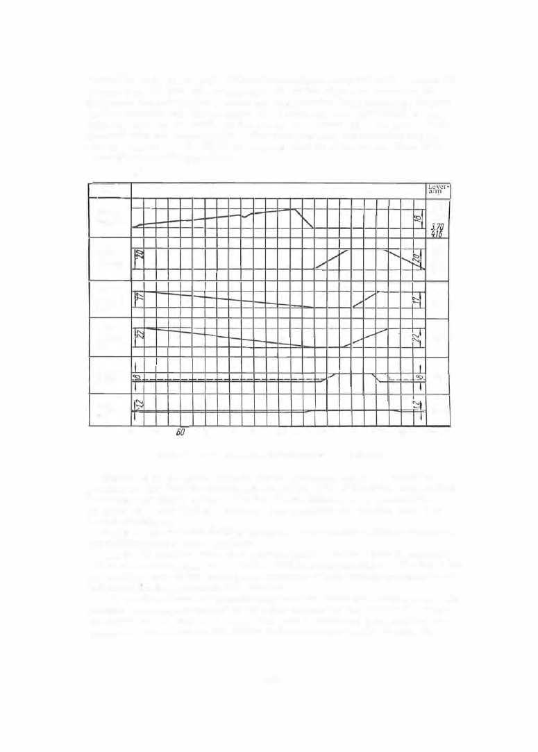
Cam 

Spindle-

feed cam 

Carriage-

lift cam 

Stud-disk 

indexing 

cam 

Barrel-

indexing 

cam 

Barrel -

lock pin 

cam 

Safety 

cam 

30 

90 

IZO 

ISO 

780  210  2'10 

270  300  330 

FIGURE 49.  Cycle  diagram  for the S-44A machine-camshaft cams 

ratlo 

'2,34 

2.80 

3,26 

0.25 

0.32 

0.38 

0.5 

QU 

084 

OZ7 

3150' 

Figure  49  is  the  cycle  diagram  for  the  camshaft  cam s .   It s hould  be 

pointed  out that the  idle  movements  cons titute  4 7  o/o  of  the  cycle tim e  in  this 

machine ,   and that in spite  of  this  fact  the  machine  is  very  p roductive: 

56  holes  can be  d rilled in  1  minute .  One  operator  can s e rvice from  4  to 

5  such  machines . 

S- 2 1 2  s emiautomatic  drilling  machine. 

This  machine  (Figure  5 0 )  se rves 

for  drilling lateral  holes in plates . 

The  S - 2 1 2  m achine  has  a  two -position plate  in  which  a p art  is  manually 

set on  the  locating pins  while  anothe r  part  is being m achined.  The holes for 

the winding stem in the watch plate are successively cente r - marked, d rilled 

and bored by three  tools  on this  m achine . 

The  machined part is  automatically  removed from  the  locating pins .  The 

machine  motions  are  c ontrolled by  cams  mounted  on the  camshaft,  which 

can  rotate  at  5 . 1 ,   6 . 4 ,   or 

rpm .  One  part  is  machined per camshaft  re­

volution.  The maximum  dim ension of the machined p art is  45 mm,  the 

249 

maximum  thickness  5 mm,  and  the  maximum  hole  diameter is  2 m m .   The 

time  taken  to  m achine  one  part  varies  between  8  and  12  sec .  The  drilling 
spindles  revolve  at  1 0, 3 00 revolutions  per minute and  a  0 . 6  kw,  3000 rpm , 
electric  motor is  use d .  

Technical data,  S-44A  machine 

Maximum drilling  diameter,  mm 

Minimum drilling diameter,  mm  . . . . . . . . . . .  

Maximum drilling depth,  mm : 

brass 

. . . . . . . . . . . . . . . . . . . . . . . • • . .  

steel 

. . . . . . . . . . . . . . . . . . . . . . . • • . .  

Accuracy of hole  diameter,  mm 

. . . . . . . . . . • . .  

Accuracy of distance between centers,  mm 

. . • • . . 

Drilling-spindle speed,  rpm 

. . . . . . . . . . . . • • . .  

Number of camshaft speeds 

. . . . . . . . . . . . • • . .  

Time for one camshaft revolution,  sec  . . .  ,  . . . . .  
Drilling-spindle feed rates,  mm/rev 

,  ,  .  ,  ,  . • . .  

Electric  motor 

. . . . . . . . . . . . . . . . . . . . . . • . .  

0.3 


0.01 
0 .02- 0.03 

1 0 ,500 

2 .85- 0.92 

0.015- 0.090 

0.65 kw , 

2800 rpm 

The  A - 224 semiautomatic  machine,  s imilar  in  design to  the  S - 2 1 2  ma­

chine,  is  used fo r  center-m arking,  drilling and threading two lateral  holes 
on the  plate  to take the  dial  leg screws .  The  two  holes  are  machined  con­

secutively and the loading plate is  rotated  1 8 0°  about its  axis  to  machine  the 

second  hole .   Holes  of  0. 3  to  1 . 2  mm  diameter are  threaded .  The  threading 

spindle  revolves  at  3 2 6 0  rpm  for threading,  and  at  5450 rpm  for  tap  with­
drawing. 

Hole Shaving in  Dies 

The  high  accuracy required of the  holes  in plates  and bridges  is  now 

achieved by  shaving them  in  die s .   The drilled  (or pierc e d )  holes  have  an 

allowance  for  shaving  (Table  7 ),  which  must  compensate for  the  deviations 

in  the  diam ete rs  and  inte raxial  distances  which  resulted from  earlier oper­
ations . 

TABLE  7 

Shaving allowance for holes  in  plates  and bridges 

A II ow ance  on the diameter for : 

Diameter of hole 

brass 

to be shaved , 

steel 

ITilll 

ab  > 80 

l<g/mm2 

"b  .;so 

kg/mm2 

0.25- 0.50 

0.08 

0.05 

0.50-1 

0.12 

0.08 

1-1.5 

0.18 

0.12 

1 .5-2 .5 

0.25 

0 .20 

2 .5- 3 .5 

0.40 

0.30 

1171 

2 5 0  

Work spindle 

Electric-motor  shaft,

� 

FIGURE 

5 0 .  

General view  and kinematic diagram of the S-212 semiautomatic 

drilling machine 

2 5 1  

For blind  holes ,  the  allowance  is  reduced by  2 5 - 30 % . 

Shaving is  the  final  hole-machining operation,  and  all  other operations 

must  therefore be  concluded before  shaving. 

The dimensions  of the  holes  obtained  by shaving are very accurate and 

the  process  its elf  is  very productive .  All  the  holes  in  a  part,  both  through 

holes  and  blind  hol es,  can be  shaved in  one  s troke  of the  press .  Up  to  24 

holes  are  shaved  in  the  plates  of pocket 

and wristwatches by one  die. 

The process  of hole shaving consists 

in  the  removal  of  chips by  means  of a 

punch  (Figure  5 1 ).  The  punch  mus t 

have  a  well -finished face  surface.  Any 

burrs  on  its  edges  would  lead  to  metal 

build-up  at the  burr and  to  the  appear­

ance of deep  longitudinal  scratches  on 

the hole surface .  Metal  build-up  on 

Die 

the  punch  is  likely  to  occur  even  with 

a  good  surface finish and,  in  order to 

p revent  it,  forced lubrication of the 

punches  (see below )  is  used in  s ome 

FIGURE 51 .  Scher>�atic representation of hole 

s having dies . 

shaving 

The  punch diameter  mus 

·. 

be  large r 

than  the  diameter of  the  s hav2d hole 

by  the  value  of  the  hole  contraction .  Hole  contraction occurs  as  a  result of 

the blunting of the punch  end which  then not only  cuts,  but also  deforms  the 

metal  fibers .  If the  hole  is  pierced by the punch,  the  metal  fibers  a re  bent 

to  a  considerable  depth,  and an elastic deformation occurs .  The  hole  con­

t raction also  depends  on the extent to  which the shaving punch  removes  a 

uniform  chip  around  the  circumferenc e .  

Hole  contraction is  dete rmined b y  the  fo rmula 

t  A. 

punc 

hole  -

For brass 

is  0 . 005  to  0 . 0 1 5  mm . 

Design 

of  shaving  dies . 

In  the  shaving  die  sl�own  in  Figure  52  the  punch 

and  the  locating pins  are  placed  in the uppe r  die  shoe together with the  strip ­

per,  and  the plate  o r  b ridge  to  be  shaved is  set in the lower shoe,  and  is 

positioned by the  guide pin  (2 ).  When the  ram  ( 1 )  is  l owered the pins  ( 3 )  

take  over the  positioning function from  the  guide  pin  ( 2  ) .  

The  advantage o f  this  design  lies  i n  the fact that both the  punches  (4 )  and 

the locating pins  ( 3 )  are  located in  the  stripper ( 5 )  and the punch holder  (6 ), 

thus  ensuring a  fixed  relationship  between the  locating and  the  s having  ele­

m ents .  This  design  gives both  highly  accurate  distances between cente rs 

and  a  uniform  removal  of  the  allowance a round  the  circumferenc e .  

I n  some dies the locating pins  ( 3 )  are i n  the  lower  shoe.  The  holding 

and locating system  is  s eparated,  in this  case,  from  the  punches,  and this 
can lead to  the  s hi.fting of the  whole  punch s ys tern  relative  to the  drilled 

holes .  In many  cases  this  leads  to imperfect shaving due  to  the  s mall  al ­
lowanc es .  

The  die  (8 )  with the punch  guide bushings  ( 9 )  which  guide  the punches  and 

permit the passage of  chips  is  fastened in the  lower  s hoe of the  die s et .   The 

2 5 2  


Content   ..  61  62  63  64   ..