Cessna 208B Grand Caravan EX. Airplane Flight Manual (2012) - page 2
SECTION 2
CESSNA
OPERATING LIMITATIONS
MODEL 208B (867 SHP)
GARMIN G1000
PLACARDS (Continued)
INTERIOR PLACARDS (Continued)
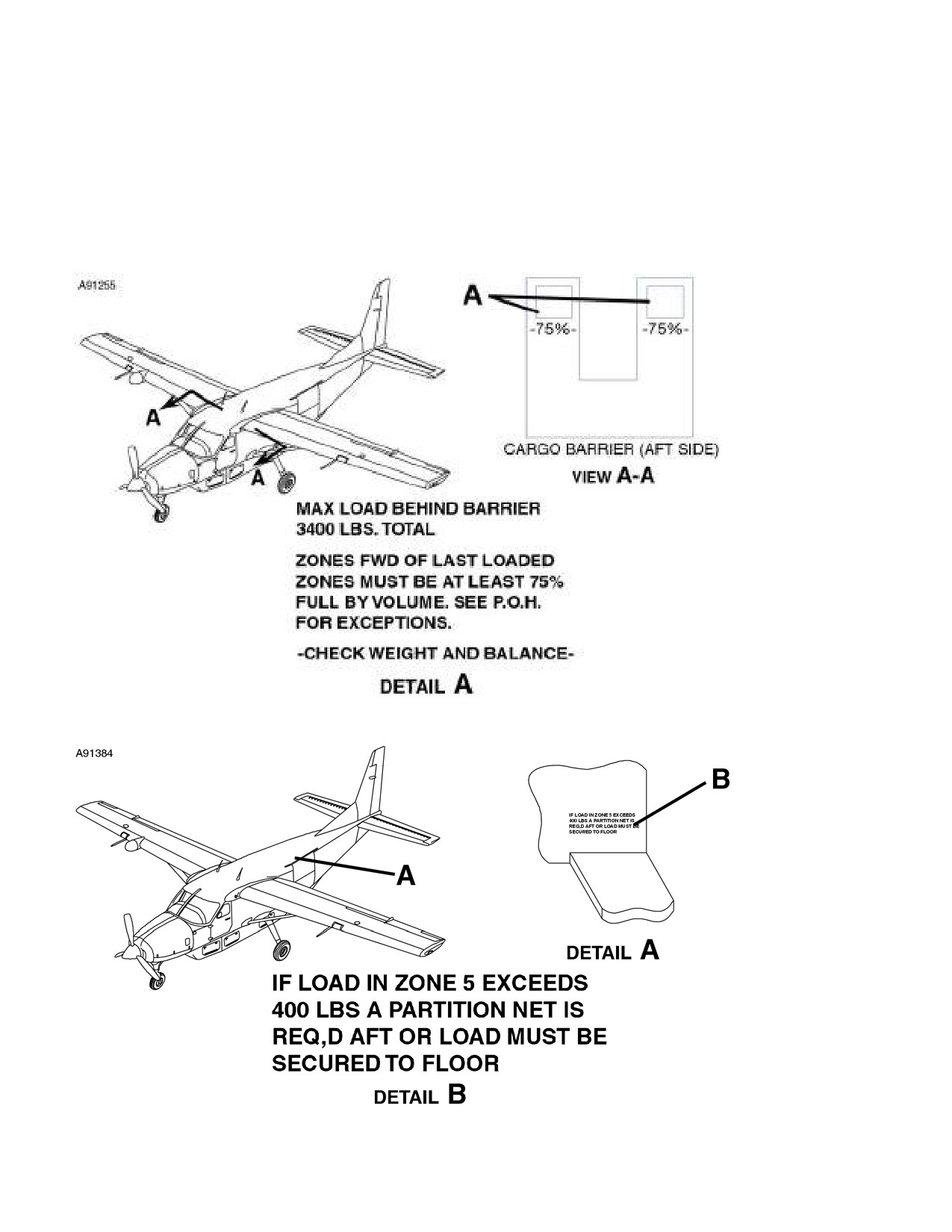
CARGO AREA
On left and right sides of the cargo barrier
(Cargo version or
Passenger version when cargo barrier is installed):
On right sidewall adjacent to Zone 5 (Cargo version only):
(Continued Next Page)
FAA APPROVED
2-48
208BPHCUS-00
U.S.

CESSNA
SECTION 2
MODEL 208B (867 SHP)
OPERATING LIMITATIONS
GARMIN G1000
PLACARDS (Continued)
INTERIOR PLACARDS (Continued)
CARGO AREA (Continued)
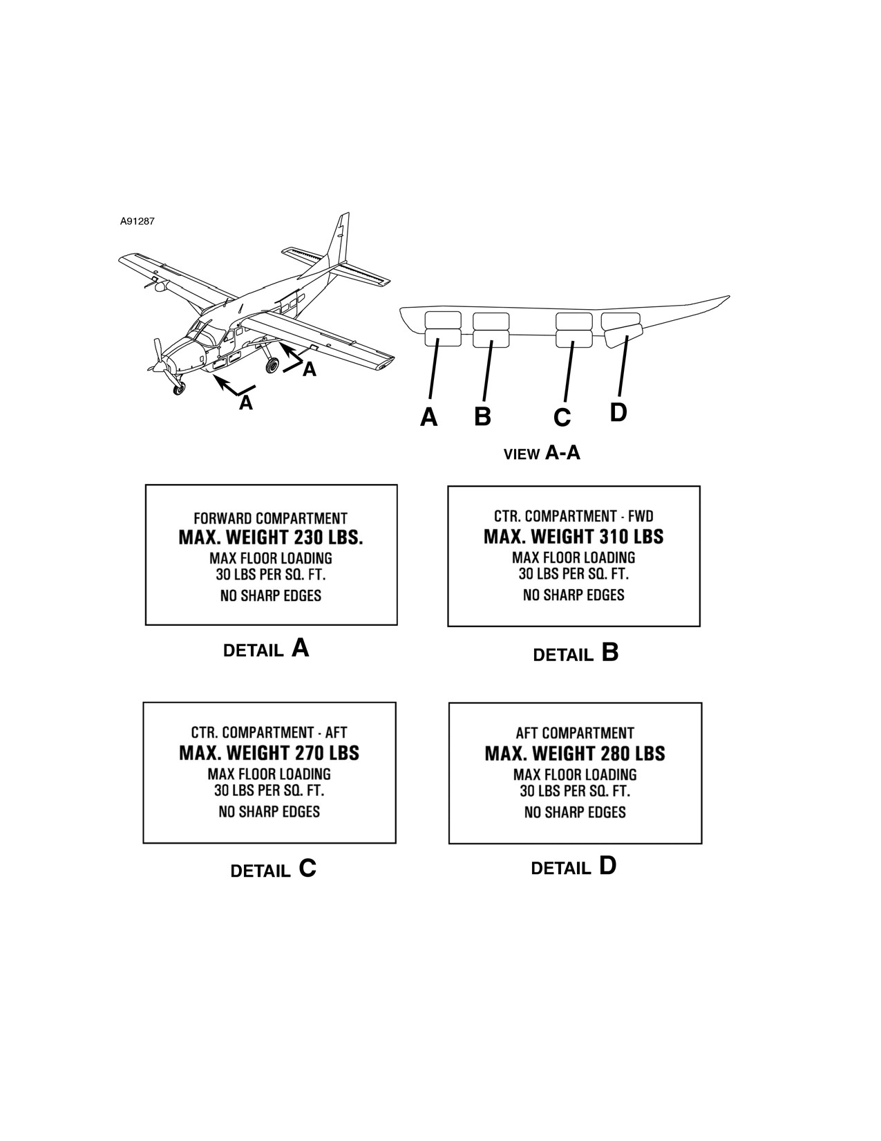
On left and right sides of cabin in appropriate zones (Cargo version
only):
(Continued Next Page)
FAA APPROVED
208BPHCUS-00
U.S.
2-49

SECTION 2
CESSNA
OPERATING LIMITATIONS
MODEL 208B (867 SHP)
GARMIN G1000
PLACARDS (Continued)
INTERIOR PLACARDS (Continued)
CARGO AREA (Continued)
On inside of lower cargo door (Cargo version only)
At each sidewall and ceiling anchor plate (except heavy duty anchor
plates with additional structural support) and at anchor plate at
center of lower cargo door (Cargo version only):
(Continued Next Page)
FAA APPROVED
2-50
208BPHCUS-00
U.S.
CESSNA
SECTION 2
MODEL 208B (867 SHP)
OPERATING LIMITATIONS
GARMIN G1000
PLACARDS (Continued)
EXTERIOR PLACARDS
On inside of cargo pod doors (if installed):
(Continued Next Page)
FAA APPROVED
208BPHCUS-00
U.S.
2-51

SECTION 2
CESSNA
OPERATING LIMITATIONS
MODEL 208B (867 SHP)
GARMIN G1000
PLACARDS (Continued)
EXTERIOR PLACARDS (Continued)
Adjacent to upper cargo door outside pushbutton and door handle
(Passenger version only):
(Continued Next Page)
FAA APPROVED
2-52
208BPHCUS-00
U.S.

CESSNA
SECTION 2
MODEL 208B (867 SHP)
OPERATING LIMITATIONS
GARMIN G1000
PLACARDS (Continued)
EXTERIOR PLACARDS (Continued)
(Continued Next Page)
FAA APPROVED
208BPHCUS-00
U.S.
2-53

SECTION 2
CESSNA
OPERATING LIMITATIONS
MODEL 208B (867 SHP)
GARMIN G1000
PLACARDS (Continued)
EXTERIOR PLACARDS (Continued)
WINGS
(Continued Next Page)
FAA APPROVED
2-54
208BPHCUS-00
U.S.

CESSNA
SECTION 2
MODEL 208B (867 SHP)
OPERATING LIMITATIONS
GARMIN G1000
PLACARDS (Continued)
EXTERIOR PLACARDS (Continued)
WINGS (Continued)
On bottom of each wing just forward of aileron:
(Continued Next Page)
FAA APPROVED
208BPHCUS-00
U.S.
2-55

SECTION 2
CESSNA
OPERATING LIMITATIONS
MODEL 208B (867 SHP)
GARMIN G1000
PLACARDS (Continued)
EXTERIOR PLACARDS (Continued)
ENGINE COMPARTMENT
On the brake fluid reservoir:
(Continued Next Page)
FAA APPROVED
2-56
208BPHCUS-00
U.S.

CESSNA
SECTION 2
MODEL 208B (867 SHP)
OPERATING LIMITATIONS
GARMIN G1000
PLACARDS (Continued)
EXTERIOR PLACARDS (Continued)
ENGINE COMPARTMENT (Continued)
Adjacent to oil dipstick/filler cap (on inertial separator duct):
(Continued Next Page)
FAA APPROVED
208BPHCUS-00
U.S.
2-57

SECTION 2
CESSNA
OPERATING LIMITATIONS
MODEL 208B (867 SHP)
GARMIN G1000
PLACARDS (Continued)
EXTERIOR PLACARDS (Continued)
ENGINE COMPARTMENT (Continued)
On firewall above battery tray:
(Continued Next Page)
FAA APPROVED
2-58
208BPHCUS-00
U.S.

CESSNA
SECTION 2
MODEL 208B (867 SHP)
OPERATING LIMITATIONS
GARMIN G1000
PLACARDS (Continued)
EXTERIOR PLACARDS (Continued)
FORWARD FUSELAGE
Above ground service plug receptacle:
(Continued Next Page)
FAA APPROVED
208BPHCUS-00
U.S.
2-59

SECTION 2
CESSNA
OPERATING LIMITATIONS
MODEL 208B (867 SHP)
GARMIN G1000
PLACARDS (Continued)
EXTERIOR PLACARDS (Continued)
FORWARD FUSELAGE (Continued)
On each side of nose strut fairing near tow limit marking:
(Continued Next Page)
FAA APPROVED
2-60
208BPHCUS-00
U.S.

CESSNA
SECTION 2
MODEL 208B (867 SHP)
OPERATING LIMITATIONS
GARMIN G1000
PLACARDS (Continued)
EXTERIOR PLACARDS (Continued)
AFT FUSELAGE
On the left side of the tailcone stinger, affixed to the rudder lock shaft
cover plate:
FAA APPROVED
208BPHCUS-00
U.S.
2-61
SECTION 2
CESSNA
OPERATING LIMITATIONS
MODEL 208B (867 SHP)
GARMIN G1000
This Page Intentionally Left Blank
FAA APPROVED
2-62
208BPHCUS-00
U.S.
CESSNA
SECTION 3
MODEL 208B 867 SHP
EMERGENCY PROCEDURES
GARMIN G1000
EMERGENCY PROCEDURES
TABLE OF CONTENTS
Page
Introduction
3-5
Airspeeds For Emergency Operation
3-6
GENERAL
3-7
Operating Procedures - General
3-7
EMERGENCY PROCEDURES
3-9
ENGINE FAILURES
3-9
Engine Failure During Takeoff Roll
3-9
Engine Failure Immediately After Takeoff
3-9
Engine Failure During Flight
3-10
Engine Flameout During Flight
3-11
AIRSTART
3-12
Starter Assist
3-12
FORCED LANDINGS
3-14
Emergency Landing Without Engine Power
3-14
Precautionary Landing With Engine Power
3-15
Ditching
3-16
SMOKE AND FIRE
3-17
Red ENGINE FIRE Annunciator Comes On
During Start On Ground
3-17
Cabin Fire During Ground Operations
3-17
Red ENGINE FIRE Annunciator Comes On In Flight
3-18
Electrical Fire In Flight
3-19
Cabin Fire
3-21
Wing Fire
3-22
(Continued Next Page)
FAA APPROVED
208BPHCUS-00
U.S.
3-1
SECTION 3
CESSNA
EMERGENCY PROCEDURES
MODEL 208B 867 SHP
GARMIN G1000
TABLE OF CONTENTS (Continued)
Page
EMERGENCY DESCENT
3-23
Smooth Air
3-23
Rough Air
3-23
ICE AND RAIN PROTECTION
3-24
The following weather conditions can be conducive
to severe in-flight icing - As required by AD 96-09-15,
Paragraph (a) (2)
3-24
Procedures for exiting the severe icing environment -
As required by AD 96-09-15, Paragraph (a) (2)
3-24
Inadvertent Icing Encounter
3-25
ENGINE MALFUNCTIONS
3-27
Red OIL PRESS LOW Annunciator Comes On
3-27
Uncommanded Engine Power Reduction To Idle
3-27
Red EMERG PWR LVR Annunciator Comes On Prior To
or During Engine Start
3-27
FUEL SYSTEM
3-28
Red RSVR FUEL LOW Annunciator Comes On
3-28
Red FUEL SELECT OFF Annunciator Comes On
During Engine Start and Aural Warning Horns Sound
3-29
Red FUEL SELECT OFF and Amber L, R, or
L-R FUEL LOW Annunciators Come On
3-29
Red FUEL SELECT OFF Annunciator Comes On
During Flight and Aural Warning Horn Sounds
3-29
Red FUEL SELECT OFF Annunciator Comes On Prior To
Engine Start and Aural Warning Horns Not Sounding
3-30
ELECTRICAL POWER SUPPLY SYSTEM MALFUNCTIONS . . . 3-31
Red VOLTAGE HIGH Annunciator Comes On
3-31
Red VOLTAGE LOW Annunciator Comes On
3-34
AUTOPILOT OR ELECTRIC TRIM FAILURE
3-36
Red PTRM Message Comes On
3-36
Red AFCS or YAW Message Comes On
3-37
(Continued Next Page)
FAA APPROVED
3-2
U.S.
208BPHCUS-00
CESSNA
SECTION 3
MODEL 208B 867 SHP
EMERGENCY PROCEDURES
GARMIN G1000
TABLE OF CONTENTS (Continued)
Page
AMPLIFIED EMERGENCY PROCEDURES
3-38
Engine Failure
3-38
Maximum Glide
3-41
Forced Landings
3-42
Ditching
3-42
Landing Without Elevator Control
3-43
Smoke And Fire
3-43
Emergency Operation In Clouds
3-45
Executing A 180° Turn In Clouds (Dual AHRS Failure)
3-46
Emergency Descent Through Clouds (Dual AHRS Failure) . . .
3-47
Recovery From Spiral Dive In The Clouds (Dual AHRS Failure) 3-48
Spins
3-49
Engine Malfunctions
3-50
Loss of Oil Pressure
3-50
Uncommanded Engine Power Reduction To Idle
3-51
Emergency Power Lever Not Stowed
3-51
Fuel System Malfunction
3-52
Inadvertent Fuel Flow Interruption
3-52
Electrical Power Supply System Malfunctions
3-54
Generator or Main Bus Malfunctions
3-54
Loss of Electrical Power
3-56
Partial Avionics Power Failure
3-57
Standby Electrical System Malfunctions
3-58
Emergency Exits
3-59
FAA APPROVED
208BPHCUS-00
U.S.
3-3
SECTION 3
CESSNA
EMERGENCY PROCEDURES
MODEL 208B 867 SHP
GARMIN G1000
This Page Intentionally Left Blank
FAA APPROVED
3-4
U.S.
208BPHCUS-00
CESSNA
SECTION 3
MODEL 208B 867 SHP
EMERGENCY PROCEDURES
GARMIN G1000
INTRODUCTION
Section 3 provides checklist and amplified procedures for coping with
emergencies that may occur. Emergencies caused by airplane or
engine malfunctions are extremely rare if proper preflight inspections
and maintenance are practiced. Enroute weather emergencies can be
minimized or eliminated by careful flight planning and good judgment
when unexpected weather is encountered. However, should an
emergency arise, the basic guidelines described in this section should
be considered and applied as necessary to correct the problem. In any
emergency situation, the most important task is continued control of the
airplane and maneuver to execute a successful landing.
Emergency procedures associated with optional or supplemental
equipment are found in Section 9, Supplements.
WARNING
There is no substitute for correct and complete
preflight planning habits and continual review to
minimize
emergencies.
Be
thoroughly
knowledgeable of hazards and conditions which
represent potential dangers. Also be aware of the
capabilities and limitations of the airplane.
FAA APPROVED
208BPHCUS-00
U.S.
3-5
SECTION 3
CESSNA
EMERGENCY PROCEDURES
MODEL 208B 867 SHP
GARMIN G1000
AIRSPEEDS FOR EMERGENCY OPERATION
ENGINE FAILURE AFTER TAKEOFF
WING FLAPS Handle UP
100 KIAS
WING FLAPS Handle LAND
80 KIAS
MANEUVERING SPEED
8807 POUNDS (3994 kg)
148 KIAS
7500 POUNDS (3401 kg)
137 KIAS
6250 POUNDS (2834 kg)
125 KIAS
5000 POUNDS (2267 kg)
112 KIAS
MAXIMUM GLIDE WITH CARGO POD
8807 POUNDS (3994 kg)
95 KIAS
7500 POUNDS (3401 kg)
87 KIAS
6250 POUNDS (2834 kg)
79 KIAS
5000 POUNDS (2267 kg)
71 KIAS
MAXIMUM GLIDE WITHOUT CARGO POD
8807 POUNDS (3994 kg)
97 KIAS
7500 POUNDS (3401 kg)
90 KIAS
6250 POUNDS (2834 kg)
82 KIAS
5000 POUNDS (2267 kg)
74 KIAS
PRECAUTIONARY LANDING WITH ENGINE POWER
WING FLAPS Handle LAND
80 KIAS
LANDING WITHOUT ENGINE POWER
WING FLAPS Handle UP
100 KIAS
WING FLAPS Handle LAND
80 KIAS
FAA APPROVED
3-6
U.S.
208BPHCUS-00
CESSNA
SECTION 3
MODEL 208B 867 SHP
EMERGENCY PROCEDURES
GARMIN G1000
GENERAL
OPERATING PROCEDURES - GENERAL
The operating procedures contained in this manual have been
developed and recommended by Cessna Aircraft Company and are
approved for use in the operation of this airplane.
This section contains the emergency and abnormal procedures for your
airplane. For your convenience, definitions of these terms are listed in
Section I. Operating procedures in this POH/AFM are organized into
Emergency, Abnormal and Normal Procedures.
Emergency procedures are generally associated with red annunciators
or messages. Some procedures, such as Maximum Glide/Emergency
Landing, are not associated with any particular message, but can
involve one or more messages. All emergency procedures are
organized by appropriate systems and include each red annunciation
or message, if applicable, exactly as it appears on the PFD, or MFD.
Emergency procedures require immediate pilot recognition and
corrective action by the crew. Red annunciators will flash and pressing
the WARNING softkey will silence the repeating chime and change the
annunciator to steady state.
Some emergency situations require immediate memorized corrective
action. These numbered steps are printed in boxes within the
emergency procedures and should be accomplished without the aid of
the checklist.
Abnormal procedures are general procedures that can be associated
with one or more amber annunciations or messages. Some procedures
are not associated with any particular annunciation or message, but
can involve one or more messages. These procedures are organized
by related systems.
An abnormal procedure is one requiring the use of special systems
and/or the alternate use of regular systems that will maintain an
acceptable level of airworthiness. These procedures require immediate
pilot awareness and subsequent crew action may be required. Amber
annunciators will initially flash and pressing the CAUTION softkey will
change the annunciation to a steady state.
(Continued Next Page)
FAA APPROVED
208BPHCUS-00
U.S.
3-7
SECTION 3
CESSNA
EMERGENCY PROCEDURES
MODEL 208B 867 SHP
GARMIN G1000
GENERAL (Continued)
OPERATING PROCEDURES - GENERAL (Continued)
NOTE
•
White annunciators provide general information, indicate
the need for additional crew awareness and the possible
necessity of future pilot action.
•
In order to avoid confusion due to multiple messages, at
critical times, some annunciator(s) are inhibited when a
Line Replaceable Unit
(LRU), such as the GEA-71
(Garmin Engine Airframe Computer), has failed.
•
Generally, the following Emergency and Abnormal
Procedures do not direct the pilot to check/reset circuit
breakers. This is considered basic airmanship and can
be accomplished at the pilot's discretion.
•
Except where specific action is required, these
procedures do not specify action when on the ground.
Conditions resulting in a red or amber message should
be corrected prior to flight. Reasons for white
annunciators should be determined prior to flight.
•
If a red or amber annunciation occurs in flight,
consideration should be given to landing at an airport
where corrective maintenance can be performed.
Normal
procedures are those recommended for routine day-to-day
preflight, flight, and postflight operation and include expanded systems
information and procedures. Some checks, as noted in the Limitations
Section of this POH/AFM, are required to assure proper system
integrity.
The Garmin G1000 Integrated Avionics System monitors most of the
airplane systems for faults or failures and displays this information to
the crew as annunciation and messages in the Crew Alerting System
(CAS) portion of the Primary Flight Display (PFD) in front of each pilot.
Some Garmin G1000 faults are also displayed as messages in the
Primary Flight Display (PFD) or Multi Function Display (MFD). These
messages are listed within the appropriate portion of the Emergency
and Abnormal procedures sections of the POH/AFM or appropriate
Garmin Cockpit Reference Guide (CRG) for 208 series airplanes.
FAA APPROVED
3-8
U.S.
208BPHCUS-00
CESSNA
SECTION 3
MODEL 208B 867 SHP
EMERGENCY PROCEDURES
GARMIN G1000
EMERGENCY PROCEDURES
Procedures in the Emergency Procedures Checklist portion of this
section shown in boxes are immediate action items which should be
committed to memory.
ENGINE FAILURES
ENGINE FAILURE DURING TAKEOFF ROLL
1. POWER Lever
BETA RANGE
2. Brakes
APPLY
3. WING FLAPS Handle
UP
IF AIRPLANE CANNOT BE STOPPED ON REMAINING RUNWAY
4. FUEL CONDITION Lever
CUTOFF
5. FUEL/OIL SHUTOFF Knob
PULL OFF
6. FUEL TANK SELECTORS
OFF
(aural warning horn will sound)
7. BATTERY Switch
OFF
ENGINE FAILURE IMMEDIATELY AFTER TAKEOFF
1. Airspeed
90 KIAS
2. PROP RPM Lever
FEATHER
3. WING FLAPS Handle
AS REQUIRED
(TO/APR recommended)
4. FUEL CONDITION Lever
CUTOFF
5. FUEL/OIL SHUTOFF Knob
PULL OFF
6. FUEL TANK SELECTORS
OFF
(aural warning horn will sound)
7. BATTERY Switch
OFF
8. Cabin Door
UNLATCH
9. Land
STRAIGHT AHEAD
FAA APPROVED
208BPHCUS-00
U.S.
3-9
SECTION 3
CESSNA
EMERGENCY PROCEDURES
MODEL 208B 867 SHP
GARMIN G1000
ENGINE FAILURES
ENGINE FAILURE DURING FLIGHT
1. Airspeed
95 KIAS
2. POWER Lever
IDLE
3. PROP RPM Lever
FEATHER
4. FUEL CONDITION Lever
CUTOFF
5. WING FLAPS Handle
UP
6. FUEL BOOST Switch
OFF
7. FUEL/OIL SHUTOFF Knob
PULL OFF
8. IGNITION Switch
NORM
9. STBY ALT PWR Switch
OFF
10. Electrical Load
REDUCE
a. AVIONICS STBY PWR Switch
OFF
b. AVIONICS BUS TIE Switch
OFF
c. CABIN Lights Switch
OFF
d. STROBE Lights Switch
OFF
e. LDG and TAXI/RECOG Lights Switches
OFF
NOTE
Keep LDG and TAXI/RECOG lights OFF until required for
approach and landing. Prior to landing, turn both LEFT and
RIGHT LDG light switches to ON.
f.
VENT AIR FANS
OFF
g.
AIR CONDITIONING (if installed)
OFF
h.
GEN CONT and
GEN FIELD Circuit Breakers
OPEN (pull out)
(top row, last two breakers on forward end)
i.
RIGHT PITOT HEAT Circuit Breaker
OPEN (pull out)
(second row, third breaker from aft end)
j.
RDNG LIGHT Circuit Breaker
OPEN (pull out)
(third row, second breaker from aft end)
k. RADAR R/T Circuit Breaker
OPEN (pull out)
(AVN BUS 1, second row, sixth breaker from left side)
l.
AVIONICS No. 2 Switch
OFF
11. BAT AMPS
CHECK
(verify below 45 amps)
12. Land as soon as possible. (refer to EMERGENCY LANDING
WITHOUT ENGINE POWER)
FAA APPROVED
3-10
U.S.
208BPHCUS-00
CESSNA
SECTION 3
MODEL 208B 867 SHP
EMERGENCY PROCEDURES
GARMIN G1000
ENGINE FAILURES (Continued)
ENGINE FLAMEOUT DURING FLIGHT
IF GAS GENERATOR SPEED (Ng) IS ABOVE 50%
1. POWER Lever
IDLE
2. IGNITION Switch
ON
AFTER SATISFACTORY RELIGHT AS EVIDENCED BY NORMAL
ITT AND Ng INDICATIONS
3. POWER Lever
AS DESIRED
4. IGNITION Switch
NORM
(if cause of flameout has been corrected)
IF GAS GENERATOR SPEED (Ng) IS BELOW 50%
1. FUEL CONDITION Lever
CUTOFF
2.
2. Refer to AIRSTART procedure on following page for engine
restart information.
FAA APPROVED
208BPHCUS-00
U.S.
3-11
SECTION 3
CESSNA
EMERGENCY PROCEDURES
MODEL 208B 867 SHP
GARMIN G1000
AIRSTART
STARTER ASSIST
1. BATTERY Switch
ON
2. AVIONICS No. 1 Switch
ON
3. Electrical Load
REDUCE
a. STBY ALT PWR Switch
OFF
b. AVIONICS No. 2 Switch
OFF
NOTE
With AVIONICS No. 2 switch in the OFF position, the
dynamic redline will become fixed at 2397 FT-LB regardless
of temperature or altitude changes. The cruise torque bug
will become inoperative and will not be shown on the EIS
torque indicator.
c. IGNITION Switch
NORM
d. Circuit Breakers
CLOSE
(push in)
e. Left LIGHTS Panel Switches (9 total)
OFF
f.
POWER OUTLET Switch(es)
OFF
g.
VENT AIR FANS
OFF
h.
AIR CONDITIONING (if installed)
OFF
i.
TEMP Control Knob
CLOSED
(rotate FULL counterclockwise)
j.
BLEED AIR HEAT Switch
OFF
4.
INERTIAL SEPARATOR
NORMAL
(push in)
5.
EMERGENCY POWER Lever
NORMAL
6.
POWER Lever
IDLE
7.
PROP RPM Lever
MIN
8.
FUEL CONDITION Lever
CUTOFF
9.
FUEL/OIL SHUTOFF Knob
ON
(push in)
10. FUEL TANK SELECTORS
BOTH ON
(Continued Next Page)
FAA APPROVED
3-12
U.S.
208BPHCUS-00
CESSNA
SECTION 3
MODEL 208B 867 SHP
EMERGENCY PROCEDURES
GARMIN G1000
AIRSTART (Continued)
STARTER ASSIST (Continued)
11.
FUEL BOOST Switch
ON
12. Altitude
20,000 FEET MAXIMUM
13. STARTER Switch
START and OBSERVE
a. IGNITION ON Annunciator
CHECK
(verify annunciator is shown)
b. OIL PSI Indicator
CHECK
(OIL PSI indicated and rising)
c. Ng Indicator
12% RPM
(minimum)
14. FUEL CONDITION Lever
LOW IDLE and OBSERVE
a. FFLOW PPH Indicator
90-140 PPH
b. ITT Indicator
MONITOR
(1090°C maximum)
c. Ng Indicator
55% RPM
(minimum)
15. STARTER Switch
OFF
16. IGNITION Switch
ON
(if in heavy precipitation or fuel tanks near empty)
17. FUEL BOOST Switch
NORM
(unless it cycles on and off; then leave ON)
18. FUEL CONDITION Lever
HIGH IDLE
19. PROP RPM Lever
SET
20. POWER Lever
SET
21. STBY ALT PWR Switch
ON
22. AVIONICS No. 2 Switch
ON
23. Electrical Equipment
AS REQUIRED
FAA APPROVED
208BPHCUS-00
U.S.
3-13
SECTION 3
CESSNA
EMERGENCY PROCEDURES
MODEL 208B 867 SHP
GARMIN G1000
FORCED LANDINGS
EMERGENCY LANDING WITHOUT ENGINE POWER
1.
Seats, Seat Belts, Shoulder Harnesses
SECURE
2.
Loose Objects
SECURE
3.
Airspeed:
100 KIAS - WING FLAPS UP
80 KIAS - WING FLAPS LAND
4.
POWER Lever
IDLE
5.
PROP RPM Lever
FEATHER
6.
FUEL CONDITION Lever
CUTOFF
7.
FUEL BOOST Switch
OFF
8.
IGNITION Switch
NORM
9.
STBY ALT PWR Switch
OFF
10. Nonessential Equipment
OFF
11.
FUEL/OIL SHUTOFF Knob
PULL OFF
12. FUEL TANK SELECTORS
OFF
(aural warning horn will sound)
13. WING FLAPS Handle
AS REQUIRED
(LAND recommended)
14. Crew Doors
UNLATCH PRIOR TO TOUCHDOWN
15. GENERATOR Switch
TRIP
16. BATTERY Switch
OFF
(when landing is assured)
17. Touchdown
SLIGHTLY TAIL LOW
18. Brakes
APPLY HEAVILY
FAA APPROVED
3-14
U.S.
208BPHCUS-00
CESSNA
SECTION 3
MODEL 208B 867 SHP
EMERGENCY PROCEDURES
GARMIN G1000
FORCED LANDINGS (Continued)
PRECAUTIONARY LANDING WITH ENGINE POWER
1.
Seats, Seat Belts, Shoulder Harnesses
SECURE
2.
Loose Objects
SECURE
3.
WING FLAPS Handle
TO/APR
4.
Airspeed
90 KIAS
5.
Selected Field
FLY OVER
(noting terrain and obstructions)
6.
Nonessential Equipment
OFF
(except BATTERY, GENERATOR and STBY ALT PWR)
7.
WING FLAPS Handle
LAND
(on final approach)
8.
Airspeed
80 KIAS
9.
Crew Doors
UNLATCH PRIOR TO TOUCHDOWN
10. STBY ALT PWR Switch
OFF
11.
GENERATOR Switch
TRIP
12. BATTERY Switch
OFF
13. Touchdown
SLIGHTLY TAIL LOW
14. POWER Lever
BETA RANGE
15. FUEL CONDITION Lever
CUTOFF
16. Brakes
APPLY HEAVILY
FAA APPROVED
208BPHCUS-00
U.S.
3-15
SECTION 3
CESSNA
EMERGENCY PROCEDURES
MODEL 208B 867 SHP
GARMIN G1000
FORCED LANDINGS (Continued)
DITCHING
1. Radio
TRANSMIT MAYDAY (on 121.5 MHz)
(give location, intentions and SQUAWK 7700)
2. Heavy Objects in Cabin
SECURE OR JETTISON
(if passenger is available to assist)
3. Seats, Seat Belts, Shoulder Harnesses
SECURE
4. WING FLAPS Handle
LAND
5. POWER
ESTABLISH 300 FT/MIN DESCENT AT 80 KIAS
6. Approach
a. High Winds, Heavy Seas
INTO THE WIND
b. Light Winds, Heavy Swells
PARALLEL TO SWELLS
7. Cabin Doors
UNLATCH
8. Face
CUSHION AT TOUCHDOWN
(with folded coat or similar object)
9. Touchdown
LEVEL ATTITUDE AT
ESTABLISHED RATE OF DESCENT
10. ELT
ACTIVATE
11. Airplane
EVACUATE THROUGH CABIN DOORS
NOTE
If necessary, open vent window and flood cabin to equalize
pressure so doors can be opened.
12. Life Vests and Raft . . INFLATE WHEN CLEAR OF AIRPLANE
WARNING
The airplane has not been flight tested in actual
ditchings, thus the above recommended procedure
is based entirely on the best judgment of Cessna
Aircraft Company.
FAA APPROVED
3-16
U.S.
208BPHCUS-00
CESSNA
SECTION 3
MODEL 208B 867 SHP
EMERGENCY PROCEDURES
GARMIN G1000
SMOKE AND FIRE
RED ENGINE FIRE ANNUNCIATOR COMES ON DURING
START ON GROUND
1. FUEL CONDITION Lever
CUTOFF
2. FUEL BOOST Switch
OFF
3. STARTER Switch
MOTOR
WARNING
It is possible to have an engine fire without an
accompanying ENGINE FIRE annunciation.
CAUTION
Do not exceed the starting cycle limitations. Refer to
Section 2, Limitations, Engine Starting Cycle Limits.
4. STARTER Switch
OFF
5. FUEL/OIL SHUTOFF Knob
PULL OFF
6. BATTERY Switch
OFF
7. Airplane
EVACUATE
8. Fire
EXTINGUISH
CABIN FIRE DURING GROUND OPERATIONS
1. POWER Lever
IDLE
2. Brakes
AS REQUIRED
3. PROP RPM Lever
FEATHER
4. FUEL CONDITION Lever
CUTOFF
5. BATTERY Switch
OFF
6. Airplane
EVACUATE
7. Fire
EXTINGUISH
FAA APPROVED
208BPHCUS-00
U.S.
3-17
SECTION 3
CESSNA
EMERGENCY PROCEDURES
MODEL 208B 867 SHP
GARMIN G1000
SMOKE AND FIRE (Continued)
RED ENGINE FIRE ANNUNCIATOR COMES ON IN FLIGHT
1. POWER Lever
IDLE
2. PROP RPM Lever
FEATHER
3. FUEL CONDITION Lever
CUTOFF
4. FUEL/OIL SHUTOFF Knob
PULL OFF
5. CABIN HEAT FIREWALL SHUTOFF Knob
PULL OFF
6. Vents
CHECK
a. Forward Side Air VENT Knobs
CLOSE (push in)
b. Overhead Air Vents
OPEN
c. VENT AIR Control Knobs
OPEN/FAN POSITION
d. AIR CONDITIONING Switch (if installed)
OFF
7. WING FLAPS Handle
TO/APR - LAND
8. Airspeed
80 - 85 KIAS
9. Forced Landing
EXECUTE
(refer to EMERGENCY LANDING WITHOUT ENGINE POWER)
FAA APPROVED
3-18
U.S.
208BPHCUS-00
CESSNA
SECTION 3
MODEL 208B 867 SHP
EMERGENCY PROCEDURES
GARMIN G1000
SMOKE AND FIRE (Continued)
ELECTRICAL FIRE IN FLIGHT
1. STBY ALT PWR Switch
OFF
2. GENERATOR Switch
TRIP
3. BATTERY Switch
OFF
WARNING
• Without electrical power all electrically operated
flight and engine indications, fuel boost pump,
EIS annunciators, WING FLAPS Handle and all
navigation and communications systems will be
inoperative.
• All standby instruments, including torque
indicator and vacuum-driven standby attitude
indicator, will be operative.
4. Vents
CLOSED (to avoid drafts)
a. Forward Side Air VENT Knobs
CLOSE (push in)
b. Overhead Air Vents
CLOSE
c. VENT AIR Control Knobs
CLOSE
d. AIR CONDITIONING Switch (if installed)
OFF
5. TEMP Control Knob
CLOSED
(rotate FULL counterclockwise)
6. BLEED AIR HEAT Switch
OFF
7. Fire Extinguisher
ACTIVATE
WARNING
Occupants should use oxygen masks (if installed)
until smoke clears. After discharging an
extinguisher within a closed cabin, ventilate the
cabin.
8. AVIONICS No. 1 and No. 2 Power Switches
OFF
WARNING
With AVIONICS No. 1 and No. 2 OFF, use standby
flight instruments.
9. All Other Electrical Switches
OFF
(Continued Next Page)
FAA APPROVED
208BPHCUS-00
U.S.
3-19
SECTION 3
CESSNA
EMERGENCY PROCEDURES
MODEL 208B 867 SHP
GARMIN G1000
SMOKE AND FIRE (Continued)
ELECTRICAL FIRE IN FLIGHT (Continued)
IF FIRE HAS NOT BEEN EXTINGUISHED
10. Forced Landing
EXECUTE
(refer to FORCED LANDINGS CHECKLIST)
IF FIRE HAS BEEN EXTINGUISHED AND ELECTRICAL POWER IS
NECESSARY FOR CONTINUED FLIGHT TO NEAREST SUITABLE
AIRPORT OR LANDING AREA
10. BATTERY Switch
ON
11.
GENERATOR Switch
RESET
12. STBY ALT PWR Switch
ON
13. Circuit Breakers
CHECK IN
(for faulty circuit; do not reset)
14. AVIONICS No. 1 and No. 2 Switches
ON
15. Electrical Switches
ON
Slowly turn switches on one at a time, while monitoring current
draw until faulty circuit is identified.
16. Vents
OPEN
(when sure that fire is completely extinguished)
a. Forward Side Air VENT Knobs
PULL ON
b. Overhead Air Vents
OPEN
c. VENT AIR Control Knobs
OPEN/FAN POSITION
d. AIR CONDITIONING Switch (if installed)
OFF
17. BLEED AIR HEAT Switch
ON (as desired)
18. TEMP Control Knob
ADJUST
(rotate clockwise)
19. Land airplane as soon as possible to inspect for damage.
WARNING
The fire extinguishing substance is toxic, and
fumes must not be inhaled for extended periods.
After discharging the extinguisher, the cabin must
be ventilated. If oxygen is available, put masks on
and start oxygen flow.
FAA APPROVED
3-20
U.S.
208BPHCUS-00
CESSNA
SECTION 3
MODEL 208B 867 SHP
EMERGENCY PROCEDURES
GARMIN G1000
SMOKE AND FIRE (Continued)
CABIN FIRE
1. STBY ALT PWR Switch
OFF
2. GENERATOR Switch
TRIP
3. BATTERY Switch
OFF
WARNING
• Without electrical power all electrically operated
flight and engine indications, fuel boost pump,
EIS annunciators, WING FLAPS Handle and all
navigation and communications systems will be
inoperative.
• All standby instruments, including torque
indicator and vacuum-driven standby attitude
indicator, will be operative.
4. Vents
CLOSED (to avoid drafts)
a. Forward Side Air VENT Knobs
CLOSE (push in)
b. Overhead Air Vents
CLOSE
c. VENT AIR Control Knobs
CLOSE
d. AIR CONDITIONING Switch (if installed)
OFF
5. TEMP Control Knob
CLOSED
(rotate FULL counterclockwise)
6. BLEED AIR HEAT Switch
OFF
7. Fire Extinguisher
ACTIVATE
WARNING
Occupants should use oxygen masks (if installed)
until smoke clears. After discharging an
extinguisher within a closed cabin, ventilate the
cabin.
8. Land airplane as soon as possible to inspect for damage.
FAA APPROVED
208BPHCUS-00
U.S.
3-21
SECTION 3
CESSNA
EMERGENCY PROCEDURES
MODEL 208B 867 SHP
GARMIN G1000
SMOKE AND FIRE (Continued)
WING FIRE
1. PITOT/STATIC HEAT Switch
OFF
2. STALL HEAT Switch
OFF
3. STROBE Lights Switch
OFF
4. NAV Lights Switch
OFF
5. LDG and TAXI/ RECOG Lights Switches
OFF
6. LEFT FUEL QTY Circuit Breakers
OPEN (pull out)
(second row, third breaker from forward end)
7. RIGHT FUEL QTY Circuit Breakers
OPEN (pull out)
(third row, third breaker from forward end)
8. RADAR R/T Circuit Breaker (if installed)
OPEN (pull out)
(AVN BUS 1, second row, sixth breaker from left side)
9. VENT AIR Control Knobs
CLOSE
10. AIR CONDITIONING Switch (if installed)
OFF
WARNING
Perform a sideslip as required to keep flames away
from the fuel tank and cabin.
11. Land as soon as possible.
FAA APPROVED
3-22
U.S.
208BPHCUS-00
CESSNA
SECTION 3
MODEL 208B 867 SHP
EMERGENCY PROCEDURES
GARMIN G1000
EMERGENCY DESCENT
SMOOTH AIR
1. Seats, Seat Belts, Shoulder Harnesses
SECURE
2. POWER Lever
IDLE
3. PROP RPM Lever
MAX
(full forward)
4. WING FLAPS
UP
5. Airspeed
175 KIAS
ROUGH AIR
1. Seats, Seat Belts, Shoulder Harnesses
SECURE
2. POWER Lever
IDLE
3. PROP RPM Lever
MAX
(full forward)
4. WING FLAPS
UP
5. Weights and Airspeed:
8807 Pounds
148 KIAS
7500 Pounds
137 KIAS
6250 Pounds
125 KIAS
5000 Pounds
112 KIAS
FAA APPROVED
208BPHCUS-00
U.S.
3-23
SECTION 3
CESSNA
EMERGENCY PROCEDURES
MODEL 208B 867 SHP
GARMIN G1000
ICE AND RAIN PROTECTION
THE FOLLOWING WEATHER CONDITIONS CAN BE
CONDUCIVE TO SEVERE IN-FLIGHT ICING - As Required
by AD 96-09-15, Paragraph (a) (2):
1. Visible rain at temperatures below
0°C (32°F) ambient air
temperature.
2. Droplets that splash or splatter on impact at temperatures below
0°C (32°F) ambient air temperature.
PROCEDURES FOR EXITING THE SEVERE ICING
ENVIRONMENT - As Required by AD 96-09-15, Paragraph
(a) (2):
These procedures are applicable to all flight phases from takeoff to
landing. Monitor the ambient air temperature. While severe icing can
form at temperatures as cold as -18°C (0°F), increased vigilance is
warranted at temperatures around freezing with visible moisture
present. If the visual cues specified in Section
2, Limitations for
identifying severe icing conditions are observed, accomplish the
following:
1. Immediately request priority handling from Air Traffic Control to
facilitate a route or an altitude change to exit the severe icing
conditions in order to avoid extended exposure to flight
conditions more severe than those for which the airplane has
been certificated.
2. Avoid abrupt and excessive maneuvering that can exacerbate
control difficulties.
3. Do not engage the autopilot.
4. If the autopilot is engaged, hold the control wheel firmly and
disengage the autopilot.
5. If an unusual roll response or uncommanded roll control
movement is observed, reduce the angle-of-attack.
6. If the flaps are extended, do not retract them until the airframe is
clear of ice.
7. Report these weather conditions to Air Traffic Control.
FAA APPROVED
3-24
U.S.
208BPHCUS-00
CESSNA
SECTION 3
MODEL 208B 867 SHP
EMERGENCY PROCEDURES
GARMIN G1000
ICE AND RAIN PROTECTION (Continued)
INADVERTENT ICING ENCOUNTER
1. IGNITION Switch
ON
2. INERTIAL SEPARATOR
BYPASS
(rotate counterclockwise and PULL out)
3. PITOT/STATIC HEAT Switch
ON
4. STALL HEAT Switch
ON
IF ABOVE 20,000 FEET
5. Airspeed
160 KIAS MAX
6. Altitude
DESCEND TO 20,000 FEET OR BELOW
(as soon as practical)
7. Turn back or change altitude to obtain an outside air
temperature that is less conducive to icing.
8. IGNITION Switch
OFF
(after 5 minutes operation)
9. BLEED AIR HEAT Switch
ON
10. TEMP Control Knob
MAX HEAT
(rotate clockwise)
11. FWD CABIN HEAT Control Knob
PUSH (full in)
12. DEFROST Control Knob
PULL (full out)
(to obtain maximum windshield defroster effectiveness)
13. PROP RPM Lever
1900 RPM
(to minimize ice build-up)
CAUTION
• If excessive vibration is noted, momentarily reduce
propeller RPM to 1600 with the PROP RPM Lever,
then rapidly move the control full forward. Cycling
the PROP RPM flexes the propeller blades and high
RPM increases centrifugal force, causing ice to shed
more readily.
• If the INERTIAL SEPARATOR is set to BYPASS at
any point due to suspected or actual icing conditions,
do not return it to NORMAL until the inertial
separator door has been visually inspected and
verified free of ice and ice protection fluid.
(Continued Next Page)
FAA APPROVED
208BPHCUS-00
U.S.
3-25
SECTION 3
CESSNA
EMERGENCY PROCEDURES
MODEL 208B 867 SHP
GARMIN G1000
ICE AND RAIN PROTECTION (Continued)
INADVERTENT ICING ENCOUNTER (Continued)
14. Plan a landing at the nearest airport. With an extremely rapid ice
build-up, select a suitable off airport landing site.
15. With an ice accumulation of 0.25 inch (6.35 mm) or more on the
wing leading edges, be prepared for significantly higher power
requirements, higher approach and stall speeds, and a longer
landing roll.
16. If necessary, set up a forward slip for visibility through the left
portion of the windshield during the landing approach.
17. Use approach speed of 120 KIAS with WING FLAPS set at TO/
APR. With ice suspected on the airframe, or operating at 5°C
(41°F) or less in visible moisture, do not extend WING FLAPS
beyond TO/APR for landing.
18. Landing Distance
MULTIPLY POH/AFM DISTANCE BY
2.2 - FLAPS UP
2.1 - FLAPS TO/APR
19. Minimum Approach Airspeed
AT OR ABOVE
120 KIAS - Flaps UP
110 KIAS - Flaps TO/APR
WARNING
With heavy ice accumulations on the horizontal
stabilizer leading edge, do not extend flaps while
enroute or holding. When landing is assured, select
the minimum flap setting required, not to exceed
TO/APR, and maintain extra airspeed consistent
with available field length. Do not retract the flaps
once they have been extended, unless required for
go-around. Then retract flaps in increments while
maintaining 5 to 10 knots extra airspeed.
20. Land on the main wheels first, avoiding a slow and high flare.
21. Missed approaches should be avoided whenever possible
because of severely reduced climb capability. However, if a go-
around is mandatory, make the decision much earlier in the
approach than normal. Apply takeoff power and maintain 95 to
110 KIAS while retracting the flaps slowly in increments.
FAA APPROVED
3-26
U.S.
208BPHCUS-00
CESSNA
SECTION 3
MODEL 208B 867 SHP
EMERGENCY PROCEDURES
GARMIN G1000
ENGINE MALFUNCTIONS
RED OIL PRESS LOW ANNUNCIATOR COMES ON
1. OIL PSI Indication
MONITOR
CAUTION
If oil pressure indications confirm warning annunciator,
proceed in accordance with ENGINE FAILURE
checklists, or at the discretion of the pilot and consistent
with safety, continue engine operation in preparation for
an emergency landing as soon as possible.
UNCOMMANDED ENGINE POWER REDUCTION TO IDLE
1. POWER Lever
IDLE
2. EMERGENCY POWER Lever . . SET POWER AS REQUIRED
(maintain 65% Ng minimum during flight)
Amber EMERG PWR LVR annunciator will come on once
EMERGENCY POWER lever is moved out of NORMAL.
CAUTION
• The EMERGENCY POWER lever overrides normal
fuel control functions and results in the direct
operation of the fuel metering valve. Utilize slow and
smooth movement of the EMERGENCY POWER
lever to avoid engine surges, and/or exceeding ITT,
Ng and torque limits.
• MAXIMUM RATED power may not be achievable at
all temperatures and altitudes when using the
EMERGENCY POWER lever.
RED EMERG PWR LVR ANNUNCIATOR COMES ON
PRIOR TO OR DURING ENGINE START
1. EMERGENCY POWER Lever
CHECK
(verify lever in NORMAL position)
FAA APPROVED
208BPHCUS-00
U.S.
3-27
SECTION 3
CESSNA
EMERGENCY PROCEDURES
MODEL 208B 867 SHP
GARMIN G1000
FUEL SYSTEM
RED RSVR FUEL LOW ANNUNCIATOR COMES ON
1. FUEL TANK SELECTORS
BOTH ON
2. IGNITION Switch
ON
3. FUEL BOOST Switch
ON
IF RED RSVR FUEL LOW ANNUNCIATOR REMAINS ON WITH
USABLE FUEL IN WING TANKS
4. Engine Indicating System
MONITOR
WARNING
Watch for signs of fuel starvation and/or amber
FUEL PRESS LOW annunciation.
5. Land as soon as possible and determine cause of the red RSVR
FUEL LOW annunciation.
IF RED RSVR FUEL LOW ANNUNCIATOR REMAINS ON AND
AMBER FUEL PRESS LOW ANNUNCIATOR COMES ON
6. Land as soon as possible. (refer to EMERGENCY LANDING
WITHOUT ENGINE POWER)
IF RED RSVR FUEL LOW ANNUNCIATOR GOES OFF WITH
USABLE FUEL IN WING TANKS
4. FUEL QTY Indicators
CHECK
(maximum fuel imbalance 200 pounds)
5. Engine Indicating System
MONITOR
6. Ignition Switch
NORM
7. Fuel BOOST Switch
NORM
8. Continue flight as planned.
FAA APPROVED
3-28
U.S.
208BPHCUS-00
CESSNA
SECTION 3
MODEL 208B 867 SHP
EMERGENCY PROCEDURES
GARMIN G1000
FUEL SYSTEM (Continued)
RED FUEL SELECT OFF ANNUNCIATOR COMES ON
DURING ENGINE START AND AURAL WARNING HORNS
SOUND
1. FUEL TANK SELECTORS
BOTH ON
IF RED FUEL SELECT OFF ANNUNCIATOR REMAINS ON
2. Determine cause and repair before next flight.
IF RED FUEL SELECT OFF ANNUNCIATOR GOES OFF AND
AURAL WARNING HORNS SILENCED
2. Continue with engine start procedure.
RED FUEL SELECT OFF AND AMBER L, R, OR L-R FUEL
LOW ANNUNCIATORS COME ON
1. FUEL TANK SELECTORS
BOTH ON
2. Fuel Balance
MONITOR
(maximum 200 pounds imbalance)
RED FUEL SELECT OFF ANNUNCIATOR COMES ON
DURING FLIGHT AND AURAL WARNING HORN SOUNDS
1. FUEL TANK SELECTORS
BOTH ON
2. Fuel Balance
MONITOR
(maximum 200 pounds imbalance)
FAA APPROVED
208BPHCUS-00
U.S.
3-29
SECTION 3
CESSNA
EMERGENCY PROCEDURES
MODEL 208B 867 SHP
GARMIN G1000
FUEL SYSTEM (Continued)
RED FUEL SELECT OFF ANNUNCIATOR COMES ON
PRIOR TO ENGINE START AND AURAL WARNING
HORNS NOT SOUNDING
1. START CONT Circuit Breaker
CLOSE (push in)
(top row, third breaker from forward end)
2. FUEL SEL WARN Circuit Breaker
CLOSE (push in)
(second row, first breaker from forward end)
NOTE
When the START CONT or FUEL SEL WARN Circuit
Breakers are in the open position, the FUEL SELECT OFF
annunciator will come on and aural warning horns will not
sound.
CAUTION
Do not close (reset) circuit breakers more than once
and only after a 2 minute cool off period.
IF RED FUEL SELECT OFF ANNUNCIATOR REMAINS ON
3. Determine cause and repair before next flight.
IF RED FUEL SELECT OFF ANNUNCIATOR GOES OFF
3. Continue with engine start procedure.
FAA APPROVED
3-30
U.S.
208BPHCUS-00
CESSNA
SECTION 3
MODEL 208B 867 SHP
EMERGENCY PROCEDURES
GARMIN G1000
ELECTRICAL POWER SUPPLY SYSTEM
MALFUNCTIONS
RED VOLTAGE HIGH ANNUNCIATOR COMES ON
1. BUS VOLTS
CHECK
If BUS VOLTS increases above 32.5, expect generator to trip
offline automatically. BUS VOLTS indication will turn red/white at
32.1 volts to give advanced warning of an automatic trip.
IF GENERATOR AUTOMATICALLY TRIPS OFFLINE WITH BUS
VOLTS ABOVE 32.5
2. GEN CONT and
GEN FIELD Circuit Breakers
CLOSE (push in)
(top row, first and second breakers from forward end)
3. GENERATOR Switch
RESET
IF GENERATOR OUTPUT RESUMES
4. BUS VOLTS and GEN AMPS
MONITOR
IF GENERATOR TRIPS OFFLINE AGAIN WITH BUS VOLTS
ABOVE 32.5
5. GENERATOR Switch
TRIP
6. AVIONICS BUS TIE Switch
ON
7. AVIONICS STBY PWR Switch
ON
8. AVIONICS NO. 1 and NO. 2 Switches
OFF
9. Electrical Load
REDUCE
a. CABIN Lights Switch
OFF
b. POWER OUTLET Switch(es)
OFF
c. BCN Lights Switch
OFF
d. LDG and TAXI/ RECOG Light Switches
OFF
NOTE
Keep LDG and TAXI/RECOG lights OFF until required for
approach and landing. Prior to landing, turn both LEFT and
RIGHT LDG light switches to ON.
(Continued Next Page)
FAA APPROVED
208BPHCUS-00
U.S.
3-31
SECTION 3
CESSNA
EMERGENCY PROCEDURES
MODEL 208B 867 SHP
GARMIN G1000
ELECTRICAL POWER SUPPLY SYSTEM
MALFUNCTIONS (Continued)
RED VOLTAGE HIGH ANNUNCIATOR COMES ON
(Continued)
9. Electrical Load
REDUCE (Continued)
e. VENT AIR FANS
OFF
f.
AIR CONDITIONING (if installed)
OFF
g.
GEN CONT and
GEN FIELD Circuit Breakers
OPEN (pull out)
(top row, last two breakers on forward end)
h. RDNG LIGHT Circuit Breaker
OPEN (pull out)
(third row, second breaker from aft end)
i.
RADAR R/T Circuit Breaker
OPEN (pull out)
(AVN BUS 1, second row, sixth breaker from left side)
j.
HF RCVR and
HF AMP Circuit Breakers
OPEN (pull out)
(AVN BUS 2, second row, fifth and sixth breakers from left
side)
k. ALT AMPS
VERIFY BELOW 75 AMPS
(continue shedding if not below 75 amps)
10. Flight
CONTINUE
NOTE
With standby alternator powering the electrical system, the
flight can continue to destination airport with the
GENERATOR OFF annunciator shown. Monitor ALT AMPS
load using ENGINE SYSTEM page.
(Continued Next Page)
FAA APPROVED
3-32
U.S.
208BPHCUS-00
CESSNA
SECTION 3
MODEL 208B 867 SHP
EMERGENCY PROCEDURES
GARMIN G1000
ELECTRICAL POWER SUPPLY SYSTEM
MALFUNCTIONS (Continued)
RED VOLTAGE HIGH ANNUNCIATOR COMES ON
(Continued)
IF GENERATOR DOES NOT AUTOMATICALLY TRIP OFFLINE
WITH BUS VOLTS ABOVE 32.5
2. GENERATOR Switch
TRIP
3. AVIONICS BUS TIE Switch
ON
4. AVIONICS STBY PWR Switch
ON
5. AVIONICS NO. 1 and NO. 2 Switches
OFF
6. Electrical Load
REDUCE
a. CABIN Lights Switch
OFF
b. POWER OUTLET Switch(es)
OFF
c. BCN Lights Switch
OFF
d. LDG and TAXI/ RECOG Light Switches
OFF
NOTE
Keep LDG and TAXI/RECOG lights OFF until required for
approach and landing. Prior to landing, turn both LEFT and
RIGHT LDG light switches to ON.
e. VENT AIR FANS
OFF
f.
AIR CONDITIONING (if installed)
OFF
g.
GEN CONT and
GEN FIELD Circuit Breakers
OPEN (pull out)
(top row, last two breakers on forward end)
h. RDNG LIGHT Circuit Breaker
OPEN (pull out)
(third row, second breaker from aft end)
i.
RADAR R/T Circuit Breaker
OPEN (pull out)
(AVN BUS 1, second row, sixth breaker from left side)
j.
HF RCVR and
HF AMP Circuit Breakers
OPEN (pull out)
(AVN BUS 2, second row, fifth and sixth breakers from left
side)
k. ALT AMPS
VERIFY BELOW 75 AMPS
(continue shedding if not below 75 amps)
7. Flight
CONTINUE
NOTE
With Standby Alternator powering the electrical system, the
flight can continue to destination airport with the
GENERATOR OFF annunciator shown. Monitor ALT AMPS
load using ENGINE SYSTEM page.
FAA APPROVED
208BPHCUS-01
U.S.
3-33
SECTION 3
CESSNA
EMERGENCY PROCEDURES
MODEL 208B 867 SHP
GARMIN G1000
ELECTRICAL POWER SUPPLY SYSTEM
MALFUNCTIONS (Continued)
RED VOLTAGE LOW ANNUNCIATOR COMES ON
1. BUS VOLTS
CHECK
CAUTION
A red VOLTAGE LOW annunciation followed by a open
(tripped) BUS 1, BUS 2 or STBY PWR circuit breaker
can indicate a feeder fault that has isolated itself. Do
not close (reset) the open breaker. The red VOLTAGE
LOW annunciation should go off after circuit breaker
opens.
2. STBY ALT PWR
VERIFY ON
IF BUS VOLTS IS LESS THAN 24.5 WITH GENERATOR OFF AND
STBY PWR INOP ANNUNCIATORS ON
3. GEN CONT and
GEN FIELD Circuit Breakers
CLOSE (push in)
(top row, last two breakers on forward end)
4. GENERATOR Switch
RESET
5. STBY ALT PWR Switch
OFF; THEN ON
IF BUS VOLTS IS STILL LESS THAN 24.5
6. GENERATOR Switch
TRIP
7. STBY ALT PWR Switch
OFF
8. Electrical Load
REDUCE
a. AVIONICS STBY PWR Switch
OFF
b. AVIONICS BUS TIE Switch
OFF
c. CABIN Lights
OFF
d. BCN Lights
OFF
e. LDG and TAXI/RECOG Lights
OFF
NOTE
Keep LDG and TAXI/RECOG lights OFF until required for
approach and landing. Prior to landing, turn both LEFT and
RIGHT LDG light switches to ON.
(Continued Next Page)
FAA APPROVED
3-34
U.S.
208BPHCUS-00
CESSNA
SECTION 3
MODEL 208B 867 SHP
EMERGENCY PROCEDURES
GARMIN G1000
ELECTRICAL POWER SUPPLY SYSTEM
MALFUNCTIONS (Continued)
RED VOLTAGE LOW ANNUNCIATOR COMES ON
(Continued)
8. Electrical Load
REDUCE (Continued)
f.
VENT AIR FANS
OFF
g.
AIR CONDITIONING (if installed)
OFF
h.
TEMP Control Knob
ADJUST
CAUTION
When BUS VOLTS drops below 23.0 the bleed air valve
will fail to the open position. Rotate the TEMP control
knob counterclockwise as necessary to control cabin
temperature.
i.
GEN CONT and
GEN FIELD Circuit Breakers
OPEN (pull out)
(top row, last two breakers on forward end)
j.
RIGHT PITOT HEAT Circuit Breaker
OPEN (pull out)
(second row, third breaker from aft end)
k. RDNG LIGHT Circuit Breaker
OPEN (pull out)
(third row, second breaker from aft end)
l.
RADAR R/T Circuit Breaker
OPEN (pull out)
(AVN BUS 1, second row, sixth breaker from left side)
m. AVIONICS No. 2 Switch
OFF
NOTE
With AVIONICS No. 2 switch in the OFF position, the
dynamic redline will become fixed at 2397 FT-LB regardless
of temperature or altitude changes. The cruise torque bug
will become inoperative and will not be shown on the EIS
torque indicator.
9. BAT AMPS
CHECK
(verify below 45 amps)
10. Land as soon as possible.
(refer to FORCED LANDINGS
procedures)
FAA APPROVED
208BPHCUS-00
U.S.
3-35
SECTION 3
CESSNA
EMERGENCY PROCEDURES
MODEL 208B 867 SHP
GARMIN G1000
AUTOPILOT OR ELECTRIC TRIM FAILURE
RED PTRM MESSAGE COMES ON
1. Control Wheel
GRASP FIRMLY
(regain control of airplane)
2. AP/TRIM DISC Button
PRESS
(high elevator control forces possible)
3. ELEVATOR TRIM
ADJUST MANUALLY
(as necessary)
NOTE
Actuate each half of the pilot and copilot manual electric
pitch trim switches separately to make sure trim does not
actuate with only one half switch.
IF RED PTRM MESSAGE REMAINS ON
4. Autopilot
DO NOT RE-ENGAGE
5. A/P CONT Circuit Breaker
OPEN (pull out)
(AVN BUS 1, second row, third breaker from left side)
WARNING
Following an autopilot, autotrim or manual electric
trim system malfunction, do not engage the
autopilot until the cause of the malfunction has
been corrected.
IF RED PTRM MESSAGE GOES OFF
4. Continue flight as planned without the use of the autopilot.
WARNING
Following an autopilot, autotrim or manual electric
trim system malfunction, do not engage the
autopilot until the cause of the malfunction has
been corrected.
FAA APPROVED
3-36
U.S.
208BPHCUS-00
CESSNA
SECTION 3
MODEL 208B 867 SHP
EMERGENCY PROCEDURES
GARMIN G1000
AUTOPILOT OR ELECTRIC TRIM FAILURE (Continued)
RED AFCS OR YAW MESSAGE COMES ON
1. A/P CONT Circuit Breaker
CLOSE (push in)
(AVN BUS 1, second row, third breaker from left side)
IF RED AFCS OR YAW MESSAGE REMAINS ON
2. Continue flight as planned without the use of the autopilot.
WARNING
Following an autopilot, autotrim or manual electric
trim system malfunction, do not engage the
autopilot until the cause of the malfunction has
been corrected.
FAA APPROVED
208BPHCUS-00
U.S.
3-37
SECTION 3
CESSNA
EMERGENCY PROCEDURES
MODEL 208B 867 SHP
GARMIN G1000
AMPLIFIED EMERGENCY PROCEDURES
ENGINE FAILURE
If an engine failure occurs during the takeoff roll, the most important
thing to do is stop the airplane on the remaining runway. Those extra
items on the checklist will provide added safety after a failure of this
type.
Prompt lowering of the nose to maintain airspeed and establish a glide
attitude is the first response to an engine failure after takeoff.
Feathering the propeller substantially reduces drag, thereby providing
increased glide distance. In most cases, the landing should be planned
straight ahead with only small changes in direction to avoid
obstructions. Altitude and airspeed are seldom sufficient to execute a
180° gliding turn necessary to return to the runway. The checklist
procedures assume that adequate time exists to secure the fuel and
electrical systems prior to touchdown.
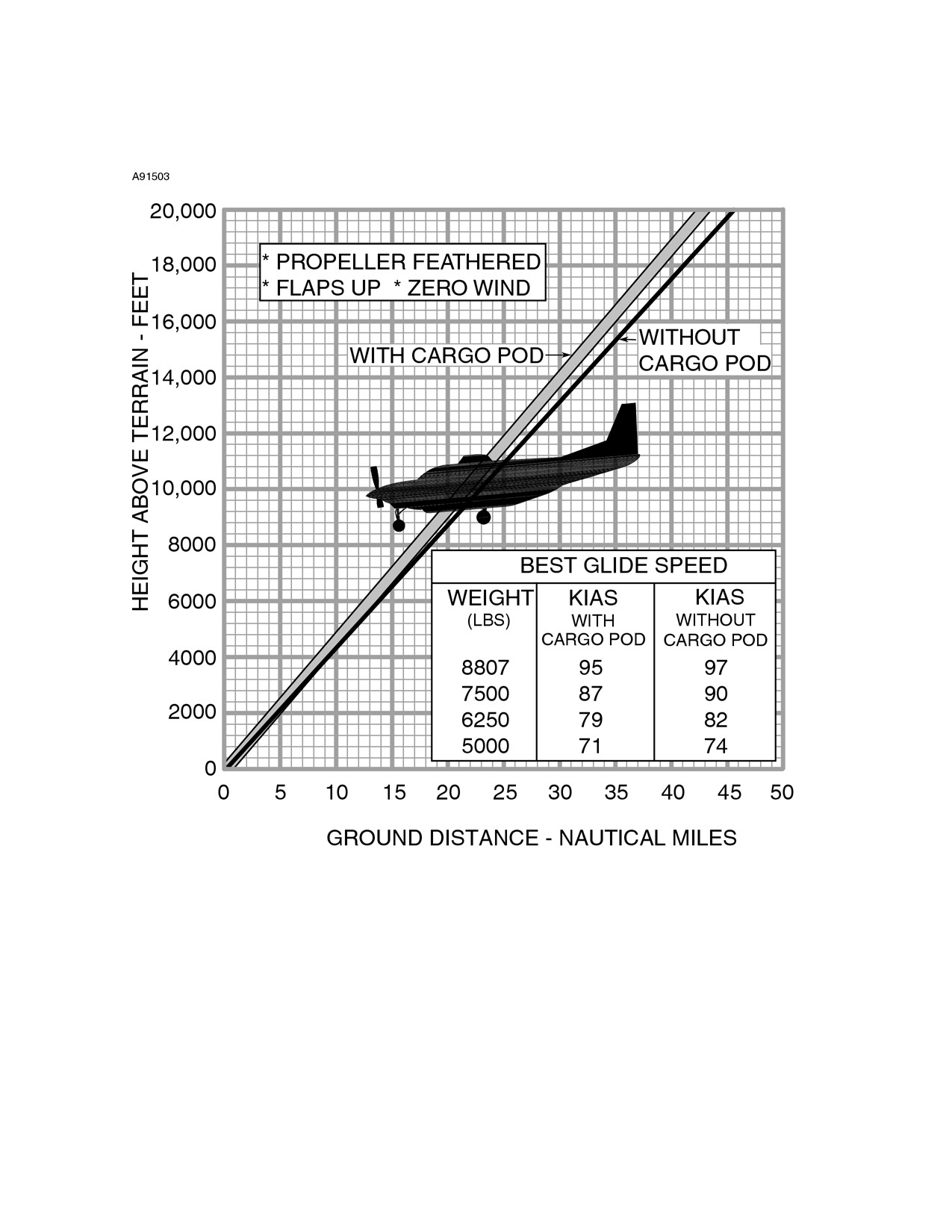
After an engine failure in flight, the best glide speed, as shown in Figure
3-1, should be established as quickly as possible. Propeller feathering
is dependent on existing circumstances and is at the discretion of the
pilot. On the other hand, to obtain the maximum glide, the propeller
must be feathered.
While gliding toward a suitable landing area, an effort should be made
to identify the cause of the power loss. An engine failure might be
identified by abnormal temperatures, mechanical noises or high
vibration levels in conjunction with the power loss. An engine failure will
be noticed by a drop in ITT, Ng and torque limits.
CAUTION
Do not attempt to restart an engine that is definitely
known to have failed.
(Continued Next Page)
FAA APPROVED
3-38
U.S.
208BPHCUS-00
CESSNA
SECTION 3
MODEL 208B 867 SHP
EMERGENCY PROCEDURES
GARMIN G1000
ENGINE FAILURE (Continued)
A flameout can result from the engine running out of fuel, or by unstable
engine operation. Unstable engine operation such as a compressor
surge, possible due to a bleed valve malfunction, can be identifiable by
an audible popping noise just before flameout. Once the fuel supply
has been restored to the engine or cause of unstable engine operation
eliminated, the engine can be restarted.
The best airstart technique is to initiate the restart procedure
immediately after a engine failure occurs, provided the pilot is certain
that the engine failure was not the result of some malfunction that might
make it hazardous to attempt a restart.
Regardless of airspeed or altitude, there is always the possibility that
the engine can restart successfully just as soon as the IGNITION is
switched ON. In an emergency, turn the IGNITION switch ON just as
soon as possible after engine failure, provided the Ng speed has not
dropped below 50%. Under these circumstances, it is not necessary to
shut off the fuel or feather the propeller. The POWER lever, however,
should be set to the IDLE position.
CAUTION
The pilot should determine the reason for power loss
before attempting an airstart.
If a engine failure has occurred and the Ng speed has dropped below
50%, the FUEL CONDITION lever should be moved to the CUTOFF
position before an airstart is attempted.
Propeller feathering is dependent on circumstances and is at the
discretion of the pilot. However, if engine OIL PSI drops below 15 PSI,
the propeller should be feathered.
(Continued Next Page)
FAA APPROVED
208BPHCUS-00
U.S.
3-39
SECTION 3
CESSNA
EMERGENCY PROCEDURES
MODEL 208B 867 SHP
GARMIN G1000
ENGINE FAILURE (Continued)
If an airstart is to be attempted, follow the AIRSTART checklist
procedures. Successful airstarts with starter assist can be achieved at
all airspeeds normally flown and up to an altitude of 14,000 feet.
However, above 14,000 feet, or with the Ng speed below 10%, starting
temperatures tend to be higher and caution is required.
CAUTION
• The FUEL CONDITION lever can be moved
momentarily to CUTOFF and then back to LOW
IDLE if
overtemperature
tendencies
are
encountered. This reduces the flow of fuel to the
combustion chamber.
• If a rise in Ng and ITT are not indicated within 10
seconds, place FUEL CONDITION lever to CUTOFF
and abort start. Refer to ENGINE FAILURE DURING
FLIGHT and EMERGENCY LANDING WITHOUT
ENGINE POWER.
If the engine starter is inoperative, refer to EMERGENCY LANDING
WITHOUT ENGINE POWER.
FAA APPROVED
3-40
U.S.
208BPHCUS-00
CESSNA
SECTION 3
MODEL 208B 867 SHP
EMERGENCY PROCEDURES
GARMIN G1000
MAXIMUM GLIDE
Figure 3-1
FAA APPROVED
208BPHCUS-00
U.S.
3-41
SECTION 3
CESSNA
EMERGENCY PROCEDURES
MODEL 208B 867 SHP
GARMIN G1000
FORCED LANDINGS
If all attempts to restart the engine fail and a forced landing is imminent,
select a suitable field and prepare for off-airport landing. Refer to
EMERGENCY LANDING WITHOUT ENGINE POWER checklist
procedures.
Before attempting an off-airport landing with engine power available,
one should fly over the landing area at a safe but low altitude to inspect
the terrain for obstructions and surface conditions. Refer to
PRECAUTIONARY LANDING WITH ENGINE POWER checklist
procedures.
The overhead FUEL TANK SELECTORS control shutoff valves at the
wing fuel tank outlets. To minimize the possibility of a fire, these FUEL
TANK SELECTORS can be set to the OFF position during the final
phase of an approach to an off-airport landing. With the FUEL TANK
SELECTORS turned OFF, there is adequate fuel in the fuel reservoir
for
3 minutes of maximum continuous power operation or
approximately 9 minutes idle power operation. A aural warning horn will
sound with both FUEL TANK SELECTORS turned OFF. If the noise of
the warning horn is too distracting, it can be silenced by opening the
START CONT circuit breaker by pulling out on the collar.
WARNING
If the precautionary landing is aborted, turn the
FUEL TANK SELECTORS to the ON position after
initiating the balked landing.
DITCHING
Prepare for ditching by securing or jettisoning heavy objects located in
the baggage area and collect folded coats for protection of occupants’
faces at touchdown. Transmit Mayday message on 121.5 MHz giving
location, intentions and squawk 7700. Avoid a landing flare because of
difficulty in judging height over a water surface.
FAA APPROVED
3-42
U.S.
208BPHCUS-00
CESSNA
SECTION 3
MODEL 208B 867 SHP
EMERGENCY PROCEDURES
GARMIN G1000
LANDING WITHOUT ELEVATOR CONTROL
Using POWER lever and ELEVATOR TRIM control, trim for
approximately 500 FPM descent with WING FLAPS set to TO/APR and
airspeed at 85 KIAS. Then control the glide angle by adjusting the
POWER lever. If required, make small trim changes to maintain
approximately 85 KIAS as power is adjusted during the approach.
The landing flare can be accomplished by a gentle power reduction
accompanied by nose up trim. At forward C.G. loadings, it may be
necessary to make a small power increase in the final flare stage to
bring the nose up and prevent touchdown on the nosewheel first. After
touchdown, set the POWER lever to IDLE.
SMOKE AND FIRE
In the event a fire is encountered, the following information will be
helpful in dealing with the emergency as quickly and safely as possible.
The Preflight Checklist, located in Section 4 of this POH, is provided to
aid the pilot in detecting conditions which could contribute to an
airplane fire. As a fire requires a combustible material, oxygen and a
source of ignition, close preflight inspection should be given to the
engine compartment and the underside of the wing and fuselage.
Leaks in the fuel or oil systems can lead to a ground or in-flight fire.
WARNING
Flight should not be attempted with known fuel or
oil leaks. The presence of fuel or unusual oil stains
can be an indication of system leaks and should be
corrected prior to flight.
(Continued Next Page)
FAA APPROVED
208BPHCUS-00
U.S.
3-43
SECTION 3
CESSNA
EMERGENCY PROCEDURES
MODEL 208B 867 SHP
GARMIN G1000
SMOKE AND FIRE (Continued)
Probable causes of an engine fire are a malfunction of the fuel control
unit and improper starting procedures. Improper procedures such as
starting with the EMERGENCY POWER lever out of NORMAL position
or introducing fuel into the engine when Ng is below 10% RPM will
cause a hot start, which can result in an engine fire. In the event that
this occurs, refer to ENGINE FIRE DURING START ON GROUND
checklist.
If an airplane fire is discovered on the ground or during takeoff, but prior
to committed flight, the airplane should be stopped and evacuated as
soon as practical.
Engine fires originating in flight must be controlled as quickly as
possible in an attempt to prevent major structural damage. Immediately
pull out on the FUEL/OIL SHUTOFF control knob and shut down the
engine. Close the CABIN HEAT FIREWALL SHUTOFF control and
forward side air vents to avoid drawing fire into the cabin, open the
overhead air vents, set WING FLAPS to LAND and reduce airspeed to
80-85 KIAS. This provides a positive cabin pressure in relation to the
engine compartment. An engine restart should not be attempted.
An open cockpit side window produces a low pressure in the cabin. To
avoid drawing the fire into the cabin, the cockpit side window should be
kept closed.
A fire or smoke in the cabin should be controlled by identifying and
shutting down the faulty system. Smoke can be removed by opening
the cabin ventilation controls. When the smoke is intense, the pilot can
choose to expel the smoke through the cockpit side window. The
cockpit side window should be closed immediately if the fire becomes
more intense when the vent window is opened.
The initial indication of an electrical fire is usually the odor of burning
insulation. In the event that this occurs, refer to ELECTRICAL FIRE IN
FLIGHT checklist.
FAA APPROVED
3-44
U.S.
208BPHCUS-00
CESSNA
SECTION 3
MODEL 208B 867 SHP
EMERGENCY PROCEDURES
GARMIN G1000
EMERGENCY OPERATION IN CLOUDS
If the vacuum pump fails in flight, the standby attitude indicator will not
be accurate. The pilot must then rely on the attitude and heading
information (from the AHRS) shown on the PFD indicators. With valid
HDG or GPS/NAV inputs, autopilot operation will not be affected.
If a single AHRS unit fails in flight (red X’s shown through the PFD
attitude and heading indicators), the pilot must rely on the cross-side
AHRS for attitude and heading information.
The autopilot will not operate if a single AHRS unit fails. The pilot must
manually fly the airplane with cross-side AHRS input. Refer to Section
7, Airplane and Systems Description, for additional details on autopilot
operations.
The following instructions assume a dual AHRS failure and that the
pilot is not very proficient at instrument flying and is flying the airplane
without the autopilot engaged.
FAA APPROVED
208BPHCUS-00
U.S.
3-45
SECTION 3
CESSNA
EMERGENCY PROCEDURES
MODEL 208B 867 SHP
GARMIN G1000
EMERGENCY OPERATION IN CLOUDS (Continued)
EXECUTING A 180° TURN IN CLOUDS (DUAL AHRS
FAILURE)
Upon inadvertently entering the clouds, an immediate turn to reverse
course and return to VFR conditions should be made as follows:
DUAL AHRS FAILURE
1. Note the non-stabilized magnetic compass heading.
2. Set rudder trim to the neutral position.
3. Using the standby attitude indicator, initiate a 15° bank left turn.
Keep feet off rudder pedals. Maintain altitude and 15° bank
angle. Continue the turn for 60 seconds, then roll back to level
flight.
4. When the compass card becomes sufficiently stable, check the
accuracy of the turn by verifying that the compass heading
approximates the reciprocal of the original heading.
5. If necessary, adjust the heading by keeping the wings level and
using the rudder to make skidding turns (the compass will read
more accurately) to complete the course reversal.
6. Maintain altitude and airspeed by cautious application of
elevator control. Keep the roll pointer and index aligned and
steer only with rudder.
FAA APPROVED
3-46
U.S.
208BPHCUS-00
CESSNA
SECTION 3
MODEL 208B 867 SHP
EMERGENCY PROCEDURES
GARMIN G1000
EMERGENCY OPERATION IN CLOUDS (Continued)
EMERGENCY DESCENT THROUGH CLOUDS
(DUAL
AHRS FAILURE)
When returning to VFR flight after a 180° turn is not practical, a descent
through the clouds to VFR conditions below can be appropriate. If
possible, obtain an ATC clearance for an emergency descent through
the clouds.
DUAL AHRS FAILURE
Choose an easterly or westerly heading to minimize non-stabilized
magnetic compass card sensitivity. Occasionally check the compass
heading and make minor corrections to hold an approximate course.
The autopilot will not operate if the AHRS unit fails. The pilot must
manually fly the airplane without AHRS input.
Before descending into the clouds, prepare for a stabilized descent as
follows:
1. Set rudder trim to neutral position.
2. Turn PITOT HEAT switch to the ON position.
3. Set power for a 500 to 800 feet per minute rate of descent.
4. Set the elevator trim for a stabilized descent at 115 KIAS.
5. Use the standby attitude indicator roll pointer and index to keep
wings level.
6. Check trend of compass card movement and make cautious
corrections with rudder to stop the turn.
7. Upon breaking out of clouds, resume normal cruising flight.
FAA APPROVED
208BPHCUS-00
U.S.
3-47
SECTION 3
CESSNA
EMERGENCY PROCEDURES
MODEL 208B 867 SHP
GARMIN G1000
EMERGENCY OPERATION IN CLOUDS (Continued)
RECOVERY FROM SPIRAL DIVE IN THE CLOUDS (DUAL
AHRS FAILURE)
DUAL AHRS FAILURE
If a spiral is entered while in the clouds, continue as follows:
1. Retard POWER lever to idle position.
2. Remove feet from rudder pedals.
3. Stop turn by carefully leveling the wings using aileron control to
align the roll index and roll pointer of the standby attitude
indicator.
4. Cautiously apply elevator back pressure to slowly reduce the
airspeed to 115 KIAS.
5. Adjust the elevator trim control to maintain an 115 KIAS glide.
6. Set rudder trim to neutral position.
7. Use aileron control to maintain wings level (keep roll pointer and
index aligned) and constant heading.
8. Resume EMERGENCY DESCENT THROUGH THE CLOUDS
procedure.
9. Upon breaking out of clouds, resume normal cruising flight.
FAA APPROVED
3-48
U.S.
208BPHCUS-00
CESSNA
SECTION 3
MODEL 208B 867 SHP
EMERGENCY PROCEDURES
GARMIN G1000
SPINS
Intentional spins are prohibited in this airplane. Should an inadvertent
spin occur, the following recovery technique can be used.
1. RETARD POWER LEVER TO IDLE POSITION.
2. PLACE AILERONS IN NEUTRAL POSITION.
3. APPLY AND HOLD FULL RUDDER OPPOSITE TO THE
DIRECTION OF ROTATION.
4. IMMEDIATELY AFTER THE RUDDER REACHES THE STOP,
MOVE THE CONTROL WHEEL BRISKLY FORWARD FAR
ENOUGH TO BREAK THE STALL. Full down elevator will be
required at aft center of gravity loadings to assure optimum
recoveries.
5. HOLD THESE CONTROL INPUTS UNTIL ROTATION STOPS.
Premature relaxation of the control inputs may extend the
recovery.
6. AS ROTATION STOPS, NEUTRALIZE RUDDER AND MAKE A
SMOOTH RECOVERY FROM THE RESULTING DIVE.
NOTE
If the rate of the spin makes determining the direction of
rotation difficult, the magenta turn rate indicator at the top of
the HSI compass card will show the rate and direction of
the turn. The HSI compass card will rotate in the opposite
direction. Hold opposite rudder to the turn vector direction.
FAA APPROVED
208BPHCUS-00
U.S.
3-49
SECTION 3
CESSNA
EMERGENCY PROCEDURES
MODEL 208B 867 SHP
GARMIN G1000
ENGINE MALFUNCTIONS
LOSS OF OIL PRESSURE
The complete loss of oil pressure, as evidenced by the red OIL PRESS
LOW annunciator and confirmed by the OIL PSI indicator reading,
implies that the pilot will eventually lose control of the propeller as the
propeller springs and counterweights drive the propeller blades into
feather and eventual engine stoppage. Therefore, if the pilot decides to
continue to operate the engine after loss of oil pressure, engine and
propeller operation should be closely monitored for indication of the
onset of propeller feathering or engine seizure. The ENGINE FAILURE
DURING FLIGHT checklist should be completed at that time.
Operation of the engine at a reduced power setting, preferably at the
minimum power required for the desired flight regime, will generally
prolong the time to loss of engine/propeller thrust.
Operation of the engine with the OIL PSI indicator in the yellow band
range is not considered critical, but is a cause for concern and should
be allowed only for the completion of the flight. Continued monitoring of
the OIL PSI indicator will provide an early indication of dropping oil
pressure due to insufficient oil supply or a malfunctioning oil pump, and
will give the pilot additional time to divert to a suitable emergency
landing area with the engine operating.
FAA APPROVED
3-50
U.S.
208BPHCUS-00
CESSNA
SECTION 3
MODEL 208B 867 SHP
EMERGENCY PROCEDURES
GARMIN G1000
ENGINE MALFUNCTIONS (Continued)
UNCOMMANDED ENGINE POWER REDUCTION TO IDLE
A malfunction in the pneumatic or governor sections of the fuel control
unit can cause engine power to decrease to minimum flow idle.
Symptoms of this type failure would be an ITT indication in the typical
idle range of 500°C to 600°C, N
g of 48% or above (increases with
altitude), and no engine response to POWER lever movement. If this
type of malfunction has occurred, the EMERGENCY POWER lever
(fuel control manual override) can be used to restore engine power. To
use the manual override system, set the POWER lever to IDLE position
and move the EMERGENCY POWER lever forward of IDLE
and
advance as required.
CAUTION
When using the fuel control manual override system,
engine response can be more rapid than when using
the POWER lever. Utilize slow and smooth movement
of the EMERGENCY POWER lever to avoid engine
surges, and/or exceeding ITT, Ng, and torque limits.
NOTE
• When using EMERGENCY POWER lever, monitor Ng%
RPM when reducing power near idle, to keep it from
decreasing below 65% in flight.
• The EMERGENCY POWER lever can have a dead
band, such that no engine response is observed during
the initial forward travel from the IDLE position.
EMERGENCY POWER LEVER NOT STOWED
The red EMERG PWR LVR annunciator was designed to alert the pilot
of the EMERGENCY POWER Lever position prior to and during the
engine start sequence. If the EMERGENCY POWER Lever is moved
from the NORMAL position at any time with the engine running, an
amber annunciator will be shown.
FAA APPROVED
208BPHCUS-00
U.S.
3-51
SECTION 3
CESSNA
EMERGENCY PROCEDURES
MODEL 208B 867 SHP
GARMIN G1000
FUEL SYSTEM MALFUNCTION
INADVERTENT FUEL FLOW INTERRUPTION
Fuel flows by gravity from the wing fuel tanks, through two fuel tank
shutoff valves at the inboard end of each wing tank, and on to the fuel
reservoir which is located under the center cabin floorboard. After
engine start, the main ejector pump, located in the reservoir, provides
fuel to the engine-driven fuel pump at approximately 10 PSI.
If the main ejector pump should malfunction, a pressure switch will
activate the amber FUEL PRESS LOW annunciator as well as turn on
the auxiliary boost pump, anytime the FUEL BOOST Switch is in the
NORM position and fuel pressure drops below approximately 2.5 PSI.
Anytime the level of fuel in the fuel reservoir drops to approximately one
half full, the red RSVR FUEL LOW annunciator will come on. If this
occurs, the pilot should immediately verify that both FUEL TANK
SELECTORS, located in the overhead panel, are in the ON position
and set the IGNITION and FUEL BOOST Switches to the ON position.
WARNING
There is only enough fuel in the reservoir for
approximately 1.5 minutes of engine operation at
maximum continuous power after the red RSVR
FUEL LOW annunciator comes on.
If the FUEL TANK SELECTORS have been left in the OFF position,
turning both valves ON will quickly fill the fuel reservoir and the red
RSVR FUEL LOW annunciator will go off. Once the cause of the RSVR
FUEL LOW condition has been determined and corrected (annunciator
will go off), the IGNITION and FUEL BOOST Switches can be returned
to their NORM positions.
(Continued Next Page)
FAA APPROVED
3-52
U.S.
208BPHCUS-00
CESSNA
SECTION 3
MODEL 208B 867 SHP
EMERGENCY PROCEDURES
GARMIN G1000
FUEL SYSTEM MALFUNCTION
INADVERTENT FUEL FLOW INTERRUPTION (Continued)
The fuel selector off warning system notifies the pilot if both FUEL
TANK SELECTORS are in the OFF position before engine start, if
either FUEL TANK SELECTOR is OFF during engine start, or if one
FUEL TANK SELECTOR is OFF and the fuel level in the tank being
used drops below approximately 25 gallons. The warning system
includes a red FUEL SELECT OFF annunciator and two aural warning
horns. If the FUEL SEL WARN circuit breaker has opened or the
START CONT circuit breaker has been opened or pulled (possibly for
ground maintenance), the red FUEL SELECT OFF annunciator will
come on even with both FUEL TANK SELECTORS in the ON position.
This annunciation serves as a warning to the pilot that the fuel selector
off warning system has been deactivated. Refer to Section 7, Airplane
and System Descriptions, Fuel Systems, for more information on the
fuel selector off warning system.
FAA APPROVED
208BPHCUS-00
U.S.
3-53
SECTION 3
CESSNA
EMERGENCY PROCEDURES
MODEL 208B 867 SHP
GARMIN G1000
ELECTRICAL POWER SUPPLY SYSTEM
MALFUNCTIONS
GENERATOR OR MAIN BUS MALFUNCTIONS
Illumination of the red VOLTAGE LOW annunciator is a warning that
the power distribution bus voltage is low enough to start discharging the
battery. Monitor the BUS VOLTS reading to verify the low bus voltage
condition. A low or
0 (zero) reading of the GEN AMPS indicator
confirms that the charge is insufficient or generator output current is 0
(zero). If the amber GENERATOR OFF annunciator comes on, it
indicates that the generator contactor has disconnected the generator
from the power distribution bus. The most likely causes of a generator
trip (disconnection) are line surges, open circuit breakers or accidental
switch operation. In these cases, follow the AMBER GENERATOR
OFF ANNUNCIATOR COMES ON checklist procedures to restore
generator operation.
The airplane is equipped with two starter contactors. One is used for
starts using external power and the other for battery starts. If either
contactor does not open after reaching approximately 46% Ng, the
amber STARTER ON annunciator will remain on. In most cases when
this occurs, the generator will not transfer over to the generator mode,
and the amber GENERATOR OFF annunciator will remain on. Under
these conditions, it will be necessary to shutdown the engine using the
Normal Checklist procedures and correct the malfunction prior to next
flight.
(Continued Next Page)
FAA APPROVED
3-54
U.S.
208BPHCUS-00
CESSNA
SECTION 3
MODEL 208B 867 SHP
EMERGENCY PROCEDURES
GARMIN G1000
ELECTRICAL POWER SUPPLY SYSTEM
MALFUNCTIONS (Continued)
GENERATOR OR MAIN BUS MALFUNCTIONS (Continued)
Illumination of the amber GENERATOR AMPS annunciator indicates 1
of 2 conditions:
1. The current load on the generator is above its rated value for
that flight condition. The pilot should reduce the electrical load,
or change flight conditions.
2. The reverse current protection of the ACU has failed. If the GEN
AMPS indicator is below -10 amps, the pilot should disconnect
the generator from the electrical system by setting the
GENERATOR switch to the TRIP position.
The electrical power distribution system consists of a primary power
distribution bus in the engine compartment which receives power from
the battery and the generator, and two (No. 1 and No. 2) main power
buses located in the circuit breaker panel. The main buses are each
connected to the power distribution bus by three feeder cables. Each
feeder cable is protected by a fuse link and a circuit breaker. This
multiple feeder system provides automatic isolation of a feeder cable
ground fault. If one of the three 30-amp feeder circuit breakers on either
bus opens, it should be assumed that a feeder cable ground fault has
been isolated, and attempted resetting of these breakers prior to
troubleshooting is not recommended. The electrical load on the
affected bus should be maintained below the remaining 60-ampere
capacity.
FAA APPROVED
208BPHCUS-00
U.S.
3-55
SECTION 3
CESSNA
EMERGENCY PROCEDURES
MODEL 208B 867 SHP
GARMIN G1000
ELECTRICAL POWER SUPPLY SYSTEM
MALFUNCTIONS (Continued)
LOSS OF ELECTRICAL POWER
The design of the electrical power system, due to the self-exciting
feature of the generator and the multiple protected busing system,
minimizes the possibility of a complete electrical power loss. However,
a fault to ground on the generator or one of the battery cables can be
identified by one or more of the following: the amber GENERATOR
OFF annunciator coming on, sudden dimming of lights, contactor
chattering, open circuit breaker(s), or arching noises. Monitoring the
GEN AMPS, ALT AMPS, BAT AMPS, and BUS VOLTS indicators on
the ELECTRICAL section of the EIS Systems page will provide further
information concerning the location of the fault, or the system affected
by the fault. In the event of the above indications, the portion of the
system containing the fault should be isolated. Following the checklist
procedures for AMBER GENERATOR OFF ANNUNCIATOR COMES
ON should result in restoration of electrical power to the distribution
buses. The electrical section of the EIS Systems page should be
monitored to make sure that ground fault currents have been shutoff
and the capacity of the remaining power source(s) is not exceeded.
CAUTION
With the loss of electrical power the bleed air valve will
fail to the open position. Rotate the TEMP control knob
counterclockwise to as necessary to control cabin
temperature.
FAA APPROVED
3-56
U.S.
208BPHCUS-00
CESSNA
SECTION 3
MODEL 208B 867 SHP
EMERGENCY PROCEDURES
GARMIN G1000
ELECTRICAL POWER SUPPLY SYSTEM
MALFUNCTIONS (Continued)
PARTIAL AVIONICS POWER FAILURE
Avionics power is supplied to No. 1 and No. 2 avionics buses from the
power distribution bus in the engine compartment through separate
protected feeder cables. In the event of a single feeder cable failure,
both avionics buses can be connected to the remaining feeder by
setting the AVIONICS BUS TIE switch to the ON position. If a ground
fault has occurred on one feeder, it will be necessary to verify the
AVIONICS No.1 or No. 2 switch, associated with the faulted feeder, is in
the OFF position before the AVIONICS BUS TIE switch will restore
power to both avionics buses. The maximum avionics load with one
feeder should be limited to 30 amperes, the maximum crosstie load is
limited to
20 amps. All nonessential avionics equipment should be
turned off.
FAA APPROVED
208BPHCUS-00
U.S.
3-57
SECTION 3
CESSNA
EMERGENCY PROCEDURES
MODEL 208B 867 SHP
GARMIN G1000
ELECTRICAL POWER SUPPLY SYSTEM
MALFUNCTIONS (Continued)
STANDBY ELECTRICAL SYSTEM MALFUNCTIONS
An operational check of the standby electrical system is performed by
following the Normal Procedures, Before Takeoff Checklist. With the
generator supplying the electrical load and the STBY ALT PWR switch
ON, neither the white STBY PWR ON or amber STBY PWR INOP
annunciators should be shown and the ALT AMPS indicator should
show 0 amps.
If the amber STBY PWR INOP annunciator is shown, it indicates that
the standby alternator has no output. If a line voltage surge or
temporary condition has tripped the Alternator Control Unit
(ACU)
offline, then cycling the STBY ALT PWR switch to OFF, then back ON,
will reset the ACU and restore standby alternator power.
If the standby electrical system is carrying more than 10 amps of the
electrical load, the white STBY PWR ON annunciator will be shown and
the ALT AMPS indicator will indicate the amount of current being
supplied by the standby electrical system.
To attempt to restore main power, refer to AMBER GENERATOR OFF
ANNUNCIATOR COMES ON procedure. If this attempt is successful,
the standby electrical system will revert to its normal no-load condition
and the amber STBY PWR ON annunciator will not be shown. If main
electrical power cannot be restored, reduce nonessential loads as
necessary to remain within the
75-amp capability of the standby
electrical system. Loads in excess of this capability will be indicated by
an amber ALTNR AMPS annunciation.
If the reverse current protection of the ACU fails, an amber ALTNR
AMPS annunciator will come on when reverse current is less than -8
amps. The pilot should disconnect the standby alternator by positioning
the STBY ALT PWR switch to OFF.
FAA APPROVED
3-58
U.S.
208BPHCUS-00
CESSNA
SECTION 3
MODEL 208B 867 SHP
EMERGENCY PROCEDURES
GARMIN G1000
EMERGENCY EXITS
Use of the crew entry doors, the passenger entry doors, and the cargo
doors for emergency ground egress from the Standard
208B is
illustrated in Figure 3-2, Emergency Exits Diagram. Emergency ground
egress from the 208B Cargomaster is accomplished by exiting the
airplane through the left and right crew entry doors as shown in Figure
3-2.
WARNING
• Do not attempt to exit the 208B Cargomaster
through the cargo doors. Since the inside of the
upper door has no handle, exit from the airplane
through these doors is not possible.
• When exiting the airplane, avoid the propeller
area.
FAA APPROVED
208BPHCUS-00
U.S.
3-59
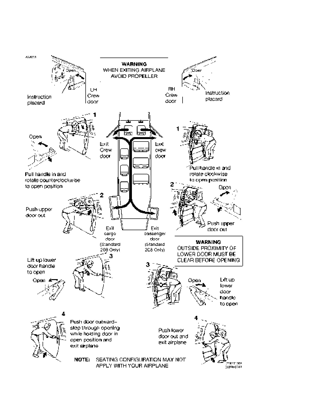
SECTION 3
CESSNA
EMERGENCY PROCEDURES
MODEL 208B 867 SHP
GARMIN G1000
EMERGENCY EXITS (TYPICAL)
Figure 3-2
FAA APPROVED
3-60
U.S.
208BPHCUS-00
CESSNA
SECTION 3
MODEL 208B 867 SHP
ABNORMAL PROCEDURES
GARMIN G1000
ABNORMAL PROCEDURES
TABLE OF CONTENTS
Page
Abnormal Landing
3-65
Landing with a Flat Main Tire
3-65
Landing with a Flat Nose Tire
3-65
Avionics/Autopilot
3-66
Amber AIL OR AIL Indication Comes On
3-66
Amber ELE OR ELE Indication Comes On
3-66
Amber RUD OR RUD Indication Comes On
3-66
Amber ALT MISCOMP Message Comes On
3-67
Amber IAS MISCOMP Message Comes On
3-70
Amber PIT, ROL or HDG MISCOMP Message Comes On
3-71
White TORQUE GAGE Annunciator Come On
3-71
Display Unit Failure
3-72
DR or LOI Indication Comes On HSI Indicator
3-73
Audio Panel Failure
3-74
Loss of Radio Tuning Functions
3-75
Transponder Failure
3-75
Red “X” on PFD Airspeed, Altitude,
and/or Vertical Speed Indicators)
3-76
Attitude Fail and/or Red “X” over Heading Display on PFD
3-77
Loss of Navigation Data (Lateral Deviation Bar
not Present and/or Glideslope Index Clears)
3-78
Inaccurate Overspeed Warning
3-78
Inaccurate Flight Director Display
3-79
Attitude and Heading Reference System (AHRS) Failure
3-80
Amber BOTH ON AHRS1 or AHRS2 Message Comes On
3-80
Amber BOTH ON GPS1 or GPS2 Message Comes On
3-80
Amber USING AHRS1 or AHRS2 Message Comes On
3-80
Air Data System Failure
3-81
Amber BOTH ON ADC1 or ADC2 Message Comes On
3-81
Amber USING ADC1 or ADC2 Message Comes On
3-81
(Continued Next Page)
FAA APPROVED
208BPHCUS-00
U.S.
3-61
SECTION 3
CESSNA
ABNORMAL PROCEDURES
MODEL 208B 867 SHP
GARMIN G1000
TABLE OF CONTENTS (Continued)
Page
Avionics Fan Failure
3-82
White MFD FAN FAIL Message Comes On
3-82
White PFD1 FAN FAIL Message Comes On
3-82
White PFD2 FAN FAIL Message Comes On
3-82
Doors
3-82
Amber DOOR UNLATCHED Annunciator Comes On In Flight .
3-82
Lower Half of Passenger Airstair Door Open
3-83
Right or Left Crew Door Opens
3-83
Cargo Pod Door(s) Open
3-83
Electrical Power Supply System Malfunctions
3-84
Amber GENERATOR OFF Annunciator Comes On
3-84
Amber STARTER ON Annunciator Comes On
After Engine Start
3-86
Amber GENERATOR AMPS Annunciator Comes On
3-86
Amber ALTNR AMPS Annunciator Comes On
3-86
Amber STBY PWR INOP Annunciator Comes On
3-87
White STBY PWR ON Annunciator Comes On
With Fuel Condition Lever Set at Low Idle
3-88
Engine
3-89
Amber CHIP DETECT Annunciator Comes On
3-89
White IGNITION ON Annunciator Comes On
3-89
Amber EMERG PWR LVR Annunciator Comes On
During Flight
3-89
Flight Controls
3-90
Asymmetric Flap Extension or
Sudden Flap Retraction on One Side
3-90
Flaps Fail to Extend or Retract
3-91
(Continued Next Page)
FAA APPROVED
3-62
U.S.
208BPHCUS-00
CESSNA
SECTION 3
MODEL 208B 867 SHP
ABNORMAL PROCEDURES
GARMIN G1000
TABLE OF CONTENTS (Continued)
Page
Fuel
3-92
Amber FUEL BOOST ON Annunciator Comes On
3-92
Amber FUEL PRESS LOW Annunciator Comes On
3-92
Amber L, R, or L-R FUEL LOW Annunciator Comes On
3-92
Ice and Rain Protection
3-93
Amber L, R or L-R P/S HEAT Annunciator Comes On
3-93
Amber STALL HEAT Annunciator Comes On
3-98
Amplified Abnormal Procedures
3-99
Elevator Mistrim
3-99
Altitude Miscompare
3-99
Airspeed Miscompare
3-99
Dual GPS Failure
3-99
Transponder Failure
3-99
ATTITUDE FAIL and/or HDG
3-100
BOTH ON ADC1 or ADC2
3-100
BOTH ON AHRS1 or AHRS2
3-100
USING ADC1 or ADC2
3-100
USING AHRS1 or AHRS2
3-100
Multi-Function Display Fan Failed
3-101
Primary Flight Display 1 Fan Failed
3-101
Primary Flight Display 2 Fan Failed
3-101
Inadvertent Opening of Airplane Doors in Flight
3-102
FAA APPROVED
208BPHCUS-00
U.S.
3-63
SECTION 3
CESSNA
ABNORMAL PROCEDURES
MODEL 208B 867 SHP
GARMIN G1000
This Page Intentionally Left Blank
FAA APPROVED
3-64
U.S.
208BPHCUS-00
CESSNA
SECTION 3
MODEL 208B 867 SHP
ABNORMAL PROCEDURES
GARMIN G1000
ABNORMAL LANDING
LANDING WITH A FLAT MAIN TIRE
1. Airplane
FLY
(as desired to lighten fuel load)
2. FUEL TANK SELECTORS
RIGHT or LEFT
NOTE
Set fuel tank selector on side with flat tire to lighten fuel
load. Maximum fuel imbalance is 200 pounds.
3. Approach
NORMAL
4. WING FLAPS
LAND
5. Touchdown
INFLATED TIRE FIRST
(hold airplane off flat tire as long as possible with aileron control)
6. Directional Control
MAINTAIN
(using brake on wheel with inflated tire as required)
LANDING WITH A FLAT NOSE TIRE
1. Passengers and Baggage
MOVE AFT (if practical)
(remain within approved C.G. envelope)
2. Approach
NORMAL
3. WING FLAPS
LAND
4. Touchdown
NOSE HIGH
(hold nosewheel off ground as long as possible during roll)
5. Brakes
MINIMUM NECESSARY
FAA APPROVED
208BPHCUS-00
U.S.
3-65
SECTION 3
CESSNA
ABNORMAL PROCEDURES
MODEL 208B 867 SHP
GARMIN G1000
AVIONICS/AUTOPILOT
AMBER AIL OR AIL INDICATION COMES ON
1. Control Wheel
GRIP FIRMLY
2. AP/TRIM DISC Button
PRESS
(high aileron control forces possible)
NOTE
The yaw damper does not need to be disconnected for this
procedure. Therefore it is permissible to use the left half of
either manual electric pitch trim switch or one press of the
AP button on the autopilot mode control panel to disconnect
the autopilot.
3. AILERON TRIM
RETRIM
4. Autopilot
ENGAGE (as desired)
AMBER ELE OR ELE INDICATION COMES ON
1. Control Wheel
GRIP FIRMLY
2. AP/TRIM DISC Button
PRESS
(high elevator control forces possible)
NOTE
The yaw damper does not need to be disconnected for this
procedure. Therefore it is permissible to use the left half of
either manual electric pitch trim switch or one press of the
AP button on the autopilot mode control panel to disconnect
the autopilot.
3. Elevator Trim Switch
AS REQUIRED
4. Autopilot
ENGAGE (as desired)
AMBER RUD OR RUD INDICATION COMES ON
1. Rudder Pedals
HOLD FIRMLY
2. AP/TRIM DISC Button
PRESS
(high rudder control forces possible)
3. RUD TRIM
AS REQUIRED
4. Autopilot and Yaw Damper
ENGAGE (as desired)
FAA APPROVED
3-66
U.S.
208BPHCUS-00
CESSNA
SECTION 3
MODEL 208B 867 SHP
ABNORMAL PROCEDURES
GARMIN G1000
AVIONICS/AUTOPILOT (Continued)
AMBER ALT MISCOMP MESSAGE COMES ON
NOTE
White TORQUE GAGE annunciator will be shown.
1. Altimeter Settings
CHECK and SET
(verify both pilot and copilot have the correct (baro) altimeter
setting)
2. PITOT/STATIC HEAT Switch
CHECK ON
(if clouds or visible moisture present)
IF AMBER ALT MISCOMP MESSAGE REMAINS ON
3. Pilot and Copilot Altitude
COMPARE
(with standby altimeter)
WARNING
The standby altimeter uses the same static sources
as the pilot’s side air data computer (ADC1). Do not
use standby altimeter as sole source in determining
correct altitude.
IF COPILOT PFD AND STANDBY ALTIMETER AGREE (PILOT
PFD DIFFERS)
4. SENSOR Softkey (pilot PFD)
PRESS
5. ADC2 Softkey
PRESS
6. PFD ADI Displays
CONFIRM
(amber BOTH ON ADC2 shown on both PFDs)
IF PILOT PFD AND STANDBY ALTIMETER AGREE (COPILOT
PFD DIFFERS)
4. Autopilot
DISENGAGE (altitude hold mode)
5. ALT STATIC AIR Control Knob
PULL ON
NOTE
The alternate static source is connected to the pilot’s PFD
and standby instruments only. Refer to Section
5,
Performance, Figure 5-1 (Sheet 2), Airspeed Calibration,
Alternate Static Source correction chart and Figure 5-2,
Altimeter Correction, Alternate Static Source correction
chart for airspeed and altimeter corrections.
(Continued Next Page)
FAA APPROVED
208BPHCUS-01
U.S.
3-67
SECTION 3
CESSNA
ABNORMAL PROCEDURES
MODEL 208B 867 SHP
GARMIN G1000
AVIONICS/AUTOPILOT (Continued)
AMBER ALT MISCOMP MESSAGE COMES ON (Continued)
IF PILOT PFD AND STANDBY ALTIMETER AGREE (COPILOT
PFD STILL DIFFERS)
6. Compare indicated altitude to GPS altitude on MFD AUX-
GPS STATUS page to aid in determining which primary
system is most accurate.
NOTE
•
When comparing indicated altitude to GPS altitude,
deviations from standard temperature or pressure can
cause indicated altitude to deviate from GPS altitude.
These errors are largest at high altitude and can amount
to over
2,500 feet under some conditions. However,
below 10,000 feet with the correct local altimeter setting
set, GPS altitude will usually be within 600 feet or better
of the correct indicated altitude. Use the following
guidelines to help estimate correct altitude for non-
standard conditions:
•
Temperatures WARMER than standard can cause GPS
altitude to read HIGHER than indicated altitude.
•
Pressures LOWER than standard can cause GPS
altitude to read HIGHER than indicated altitude.
IF ABLE TO IDENTIFY ACCURATE ALTITUDE SOURCE
7.
Use SENSOR reversion to select most accurate ADC on
both PFDs.
8.
Land as soon as practical.
FAA APPROVED
3-68
U.S.
208BPHCUS-01
CESSNA
SECTION 3
MODEL 208B 867 SHP
ABNORMAL PROCEDURES
GARMIN G1000
AVIONICS/AUTOPILOT (Continued)
AMBER ALT MISCOMP MESSAGE COMES ON (Continued)
IF UNABLE TO IDENTIFY ACCURATE ALTITUDE SOURCE
7.
Land as soon as practical. Consider diversion to visual
conditions.
8.
Maintain altitudes based on LOWEST indicated altitude.
9.
ATC
ADVISE (of inability to verify correct altitude)
10. If unable to descend into visual conditions, plan ILS
approach with course intercept well outside the Final
Approach Fix (FAF).
11. Once glideslope is captured, determine most accurate
altitude source when crossing FAF.
12. Reference ILS Decision Height to most accurate altimeter
based on FAF crossing.
WARNING
TAWS alerts are based on GPS altitude and position
information and are independent of ADC data. If a
TAWS alert is received, it should be considered
valid and appropriate terrain avoidance action
should be taken.
IF AMBER ALT MISCOMP MESSAGE GOES OFF
3. Continue flight as planned.
FAA APPROVED
208BPHCUS-01
U.S.
3-69
SECTION 3
CESSNA
ABNORMAL PROCEDURES
MODEL 208B 867 SHP
GARMIN G1000
AVIONICS/AUTOPILOT (Continued)
AMBER IAS MISCOMP MESSAGE COMES ON
1. Pilot and Copilot Airspeed
COMPARE
(with standby airspeed indicator)
2. PITOT/STATIC HEAT Switch
CHECK ON
(if clouds or visible moisture present)
WARNING
The standby airspeed indicator uses the same
pitot-static sources as the pilot’s side air data
computer (ADC1). Do not use standby airspeed
indicator as sole source in determining correct
airspeed.
IF COPILOT PFD AND STANDBY AIRSPEED AGREE (PILOT PFD
DIFFERS)
3. SENSOR Softkey (Pilot PFD)
PRESS
4. ADC2 Softkey
PRESS
5. PFD ADI Displays
CONFIRM
(amber BOTH ON ADC2 shown on both PFDs)
IF PILOT PFD AND STANDBY AIRSPEED AGREE (COPILOT PFD
DIFFERS)
3. Pilot and Copilot Altitude
COMPARE
IF ALTITUDES AGREE
4. Airspeed
120 KIAS MINIMUM (on slowest indicator)
5. Monitor all three airspeed indicators during changes in power
setting or altitude to determine which indicators are inaccurate.
Indications of inaccurate airspeed include:
a. No change in indicated airspeed when power changed and
altitude maintained.
b. Indicated airspeed increases when climbing or decreases
when descending.
6. Use SENSOR reversion to select most accurate ADC on the
affected PFD.
7. Airspeed
RESUME NORMAL SPEEDS
IF ALTITUDES DO NOT AGREE
4. Refer to AMBER ALT MISCOMP MESSAGE COMES ON
procedure to determine most accurate ADC.
FAA APPROVED
3-70
U.S.
208BPHCUS-00
CESSNA
SECTION 3
MODEL 208B 867 SHP
ABNORMAL PROCEDURES
GARMIN G1000
AVIONICS/AUTOPILOT (Continued)
AMBER PIT, ROL OR HDG MISCOMP MESSAGE COMES
ON
This message is displayed when the G1000 detects a difference
between the pilot’s and copilot’s attitude or heading information
(displayed in the upper right of the PFD). Refer to Garmin G1000
Cockpit Reference Guide for additional information.
AMBER PIT OR ROL MISCOMP INDICATION
1. Refer to standby attitude indicator to determine which AHRS is
providing the most accurate data.
2. Use SENSOR reversion to select the most accurate AHRS on
the affected PFD.
AMBER HDG MISCOMP INDICATION
1. Refer to magnetic compass to determine which AHRS is
providing the most accurate heading information.
2. Use SENSOR reversion to select the most accurate AHRS on
the affected PFD.
NOTE
Operation of the air conditioner may cause compass
deviation of more than 10 degrees. The air conditioning
system switch must be turned OFF prior to referencing the
magnetic compass heading.
WHITE TORQUE GAGE ANNUNCIATOR COMES ON
Indicates when there is an ALT MISCOMP message, red “X” through
the OAT, Altitude, Airspeed and Vertical Speed indicators on PFD1
or a 5°C temperature difference between OAT’s on PFD1 and PFD2.
1. Power Settings
CHECK
NOTE
With a white TORQUE GAGE annunciation, the dynamic
redline will become fixed at
2397 FT-LB regardless of
temperature or altitude changes. The cruise torque bug will
become inoperative and will not be shown on the EIS
torque indicator. Refer to Section 5, Performance, for the
appropriate power settings.
FAA APPROVED
208BPHCUS-00
U.S.
3-71
SECTION 3
CESSNA
ABNORMAL PROCEDURES
MODEL 208B 867 SHP
GARMIN G1000
AVIONICS/AUTOPILOT (Continued)
DISPLAY UNIT FAILURE
This is indicated by a complete loss of image on a display. If only
individual elements of the display are failed, refer to appropriate
procedures for the individual failures.
IF PILOT’S PFD FAILED
1. DISPLAY BACKUP Button
PRESS (if required)
Flight and EICAS information will be displayed on the MFD. EIS
information will not be displayed on copilot’s PFD.
NOTE
The PFD CDI SYNC and BARO SYNC settings must be ON
to allow the copilot’s PFD controls to affect settings on the
MFD. These settings are accessible using the PFD MENU
button.
2. Flight Director
TRANSFER
(Press XFR button to operating PFD)
3. FD/AUTOPILOT Modes
RESELECT and REENGAGE
(as required)
4. Transponder
SWITCH
(to operating transponder)
5. COM and NAV Radios
SWITCH
(to operating COM and NAV radios)
6. PFD Controls
USE OPERATING PFD
(for required data entry (Com, Nav, Baro setting, etc.))
IF MFD FAILED
1. DISPLAY BACKUP Button
PRESS
(EIS information will be displayed only on pilot’s PFD)
IF COPILOT’S PFD FAILED
No action is necessary. Normal operation on pilot’s PFD and MFD
will not be affected by loss of copilot’s PFD.
FAA APPROVED
3-72
U.S.
208BPHCUS-00
CESSNA
SECTION 3
MODEL 208B 867 SHP
ABNORMAL PROCEDURES
GARMIN G1000
AVIONICS/AUTOPILOT (Continued)
DR OR LOI INDICATION COMES ON HSI INDICATOR
IF ALTERNATE NAVIGATION SOURCES (ILS, LOC, VOR, DME,
ADF) ARE AVAILABLE
1. Navigation
USE ALTERNATE SOURCES
IF NO ALTERNATE NAVIGATION SOURCES ARE AVAILABLE
Dead Reckoning (DR) Mode active when airplane more than 30 NM
from destination airport.
1. Navigation
USE DR MODE
(use airplane symbol and magenta course line on map display)
WARNING
• All information normally derived from GPS turns
amber. All of this information will become more
inaccurate over time.
• TAWS will be inoperative.
NOTE
• DR mode uses heading, airspeed, and the last known
GPS position to estimate the airplane’s current position.
• All maps with an airplane symbol show a ghosted
airplane and a DR label.
(Continued Next Page)
FAA APPROVED
208BPHCUS-00
U.S.
3-73
SECTION 3
CESSNA
ABNORMAL PROCEDURES
MODEL 208B 867 SHP
GARMIN G1000
AVIONICS/AUTOPILOT (Continued)
DR OR LOI INDICATION COMES ON HSI INDICATOR
(Continued)
Loss Of Integrity (LOI) Mode active when airplane is within 30 NM of
destination airport. Distance calculated from the previous GPS or DR
position.
1. Navigation
FLY
Towards known visual conditions or available terminal
navigation sources. Use ATC or other information sources as
possible.
NOTE
• All information derived from GPS or DR is removed from
displays.
• The airplane symbol is removed from all maps. The map
will remain centered at the last known position. NO GPS
POSITION shown in center of map.
• TAWS will be inoperative.
AUDIO PANEL FAILURE
Audio panel failure may be indicated by a GMA FAIL message or the
inability to communicate using the audio panel. This failure may also be
accompanied by the loss of some aural warnings such as Altitude Alert,
Autopilot Disconnect, TAWS, and Traffic alerts.
1. AUDIO 1 Circuit Breaker
OPEN (pull out)
(AVN BUS 1, second row, first breaker from left side)
2. COM Radio
USE COM1 FOR COMMUNICATION
NOTE
In the event of an audio panel failure, a fail-safe circuit
connects the pilot’s headset directly to the COM 1 radio.
The speakers will be inoperative.
FAA APPROVED
3-74
U.S.
208BPHCUS-00
CESSNA
SECTION 3
MODEL 208B 867 SHP
ABNORMAL PROCEDURES
GARMIN G1000
AVIONICS/AUTOPILOT (Continued)
LOSS OF RADIO TUNING FUNCTIONS
1. COM Frequency Toggle Button
(affected PFD)
PRESS AND HOLD
(for 2 seconds)
NOTE
This procedure will tune the active COM field to the
emergency frequency 121.5. Certain failures of the tuning
system will automatically tune 121.5 without pilot action.
TRANSPONDER FAILURE
1. TRANSPONDER
SELECT OPPOSITE
a. PFD XPDR Softkey
PRESS
b. XPDR1 or XPDR2 Softkey
PRESS
(to select opposite transponder)
2. XPDR1 or XPDR2 Circuit Breaker (affected side)
OPEN
(pull out)
NOTE
The second transponder is an option on the 208B.
FAA APPROVED
208BPHCUS-00
U.S.
3-75
SECTION 3
CESSNA
ABNORMAL PROCEDURES
MODEL 208B 867 SHP
GARMIN G1000
AVIONICS/AUTOPILOT (Continued)
RED X ON PFD AIRSPEED, ALTITUDE, AND/OR
VERTICAL SPEED INDICATORS
This indicates a loss of valid air data system information to the
respective system.
IF BOTH SIDES
1. Airspeed and Attitude
MONITOR
(using standby instruments)
2. Land as soon as practical.
IF ONE SIDE ONLY
1. Affected PFD SENSOR Softkey
PRESS
2. Affected PFD ADC1 or ADC2 Softkey
SELECT
(opposite side ADC)
3. PFD ADI Displays
CONFIRM
(amber BOTH ON ADC1 or ADC2 shown on both PFDs)
FAA APPROVED
3-76
U.S.
208BPHCUS-00
CESSNA
SECTION 3
MODEL 208B 867 SHP
ABNORMAL PROCEDURES
GARMIN G1000
AVIONICS/AUTOPILOT (Continued)
ATTITUDE FAIL AND/OR RED X OVER HEADING DISPLAY
ON PFD
IF BOTH SIDES
1. Attitude
MONITOR
(using standby attitude gyro)
NOTE
Turn off air conditioner to reference magnetic compass.
2. Heading
MONITOR
(using magnetic compass)
3. Land as soon as practical.
NOTE
• The autopilot will disconnect and may not be reengaged.
• Reference the GPS track on MFD/PFD map to improve
situational awareness. GPS will continue to display
correct GPS based map, position, and track.
• Air conditioner will affect the magnetic compass.
IF ONE SIDE ONLY
1. Standby Attitude Gyro
MONITOR
2. Affected PFD SENSOR Softkey
PRESS
3. Affected PFD AHRS1 or AHRS2 Softkey
SELECT
(opposite side AHRS)
4. PFD ADI Displays
CONFIRM
(amber BOTH ON AHRS1 or AHRS2 shown on both PFDs)
NOTE
The autopilot will disconnect and may not be reengaged.
FAA APPROVED
208BPHCUS-00
U.S.
3-77
SECTION 3
CESSNA
ABNORMAL PROCEDURES
MODEL 208B 867 SHP
GARMIN G1000
AVIONICS/AUTOPILOT (Continued)
LOSS OF NAVIGATION DATA (LATERAL DEVIATION BAR
NOT PRESENT AND/OR GLIDESLOPE INDEX CLEARS)
This indicates a loss of data from the selected NAV source. Refer to
Garmin G1000 Cockpit Reference Guide for additional information.
1. Opposite NAV Source
SELECT
2. PFD HSI Displays
CONFIRM OPPOSITE
(LOC1/LOC2 or VOR1/VOR2 shown on both PFDs)
INACCURATE OVERSPEED WARNING
Indicated by overspeed warning tone sounding when airspeed is below
the limit speed.
1. AIRSPEED
CROSS CHECK
(with opposite PFD)
2. AIRSPEED
REDUCE
(as required)
IF BOTH AIRSPEEDS INDICATE BELOW VMO AND TONE STILL
SOUNDS
3. AIRSPEED WARN Circuit Breaker
OPEN (pull out)
(fifth row, third breaker from forward end)
4. Land as soon as practical.
IF AIRSPEEDS DO NOT AGREE
3. Refer to IAS MISCOMP procedure.
FAA APPROVED
3-78
U.S.
208BPHCUS-00
CESSNA
SECTION 3
MODEL 208B 867 SHP
ABNORMAL PROCEDURES
GARMIN G1000
AVIONICS/AUTOPILOT (Continued)
INACCURATE FLIGHT DIRECTOR DISPLAY
Indicated by one or both flight directors commanding attitude contrary
to intended flight path.
1. AP/TRIM DISC Button
PRESS
2. Attitude
CROSS CHECK BOTH PFDs
(with the standby attitude indicator)
3. Flight Director Modes
RESELECT
(as desired)
NOTE
If continued use of the flight director is desired, it is
recommended that only basic modes (i.e., ROL and PIT) be
selected initially. If this proves satisfactory, HDG and ALT
may then be selected. Make sure navigation systems are
set up correctly prior to attempting to engage NAV mode.
4. Autopilot
ENGAGE AS DESIRED
(if flight director commands are appropriate)
FAA APPROVED
208BPHCUS-00
U.S.
3-79
SECTION 3
CESSNA
ABNORMAL PROCEDURES
MODEL 208B 867 SHP
GARMIN G1000
ATTITUDE AND HEADING REFERENCE SYSTEM
(AHRS) FAILURE
AMBER BOTH ON AHRS1 OR AHRS2 MESSAGE COMES
ON
1. PFD SENSOR Softkey
PRESS
(displaying data from opposite side AHRS)
2. PFD AHRS1 or AHRS2 Softkey
SELECT ON-SIDE AHRS
(AHRS1 for Pilot PFD, AHRS2 for Copilot PFD)
3. PFD Displays
CONFIRM
(amber BOTH ON AHRS1 or AHRS2 message goes off both
PFDs and no red X on PFD 1 or PFD 2 attitude indicator)
AMBER BOTH ON GPS1 OR GPS2 MESSAGE COMES ON
1. GPS Status
CHECK
a. Select MFD
AUX-GPS STATUS PAGE
b. Select GPS1 then GPS2 softkeys and verify sufficient
satellite reception.
AMBER USING AHRS1 OR AHRS2 MESSAGE COMES ON
1. Pilot’s PFD SENSOR Softkey
PRESS
2. PFD AHRS1 Softkey
PRESS
3. PFD Displays
CONFIRM
(amber BOTH ON AHRS1 message shown on both PFDs)
4. Copilot’s PFD SENSOR Softkey
PRESS
5. PFD AHRS2 Softkey
PRESS
6. PFD Displays
CONFIRM
(amber BOTH ON AHRS2 message shown on both PFDs)
7. PFD Displays
CONFIRM
(amber BOTH ON AHRS1 or AHRS2 message goes off on both
PFDs)
FAA APPROVED
3-80
U.S.
208BPHCUS-00
CESSNA
SECTION 3
MODEL 208B 867 SHP
ABNORMAL PROCEDURES
GARMIN G1000
AIR DATA SYSTEM FAILURE
AMBER BOTH ON ADC1 OR ADC2 MESSAGE COMES ON
1. PFD SENSOR Softkey
PRESS
(displaying data from opposite side ADC)
2. PFD ADC1 or ADC2 Softkey
SELECT ON-SIDE ADC
(ADC1 for Pilot PFD, ADC2 for copilot PFD)
3. PFD Displays
CONFIRM
(amber BOTH ON ADC1 or ADC2 message goes off of both
PFDs and no red X on PFD 1 or PFD 2 airspeed indicator)
AMBER USING ADC1 OR ADC2 MESSAGE COMES ON
1. Pilot’s PFD SENSOR Softkey
PRESS
2. PFD ADC1 Softkey
PRESS
3. PFD Displays
CONFIRM
(amber BOTH ON ADC1 message shown on both PFDs)
4. Copilot’s PFD SENSOR Softkey
PRESS
5. PFD ADC2 Softkey
PRESS
6. PFD Displays
CONFIRM
(amber BOTH ON ADC2 message shown on both PFDs)
7. PFD Displays
CONFIRM
(amber BOTH ON ADC1 or ADC2 message goes off on both PFDs)
FAA APPROVED
208BPHCUS-00
U.S.
3-81
SECTION 3
CESSNA
ABNORMAL PROCEDURES
MODEL 208B 867 SHP
GARMIN G1000
AVIONICS FAN FAILURE
WHITE MFD FAN FAIL MESSAGE COMES ON
1. DECK SKIN FAN Circuit Breaker
CLOSE (push in)
(fourth row, last breaker on forward end)
WHITE PFD1 FAN FAIL MESSAGE COMES ON
1. DECK SKIN FAN Circuit Breaker
CLOSE (push in)
(fourth row, last breaker on forward end)
WHITE PFD2 FAN FAIL MESSAGE COMES ON
1. DECK SKIN FAN Circuit Breaker
CLOSE (push in)
(fourth row, last breaker on forward end)
DOORS
AMBER DOOR UNLATCHED ANNUNCIATOR COMES ON
IN FLIGHT
1. Airspeed
MAINTAIN LESS THAN 100 KIAS
2. WING FLAPS
LAND
NOTE
Wing downwash with flaps extended will move the doors
near their normally closed position.
3. If available or practical, have a second crew member go aft to
close and latch door.
IF DOOR STILL OPEN AND ANNUNCIATOR REMAINS ON
4. SEAT BELT Light Switch
ON
5. NO SMOKE Light Switch
ON
6. Approach and Landing
NORMAL
IF DOOR CLOSED AND ANNUNCIATOR GOES OFF
4. Continue flight as planned.
FAA APPROVED
3-82
U.S.
208BPHCUS-00
CESSNA
SECTION 3
MODEL 208B 867 SHP
ABNORMAL PROCEDURES
GARMIN G1000
DOORS (Continued)
LOWER HALF OF PASSENGER AIRSTAIR DOOR OPEN
1. Airspeed
MAINTAIN LESS THAN 100 KIAS
2. Flight Controls
MANEUVER
(for return for landing)
3. WING FLAPS
LAND
4. Approach
NORMAL
5. Landing
SLIGHTLY TAIL LOW
(avoid nose high flare)
RIGHT OR LEFT CREW DOOR OPENS
1. Airspeed
MAINTAIN LESS THAN 125 KIAS
2. Door
PULL CLOSED and LATCH
CARGO POD DOOR(S) OPEN
1. Airspeed
MAINTAIN LESS THAN 125 KIAS
2. Land
AS SOON AS PRACTICAL
a. Approach
NORMAL
b. Landing
AVOID A NOSE HIGH FLARE
FAA APPROVED
208BPHCUS-00
U.S.
3-83
SECTION 3
CESSNA
ABNORMAL PROCEDURES
MODEL 208B 867 SHP
GARMIN G1000
ELECTRICAL POWER SUPPLY SYSTEM
MALFUNCTIONS
AMBER GENERATOR OFF ANNUNCIATOR COMES ON
1. BUS VOLTS and GEN AMPS
CHECK and MONITOR
2. STBY ALT PWR Switch
VERIFY ON
IF BUS VOLTS LESS THAN 28.5
3. GEN AMPS
CHECK
IF GEN AMPS IS 0
a. GEN CONT and
GEN FIELD Circuit Breakers
CLOSE (push in)
(top row, first and second breakers from forward end)
b. GENERATOR Switch
RESET
IF GENERATOR OUTPUT RESUMES
c. BUS VOLTS and GEN AMPS
MONITOR
IF GENERATOR TRIPS OFFLINE AGAIN WITH BUS VOLTS
ABOVE 32.5
d. GENERATOR Switch
TRIP
e. AVIONICS BUS TIE Switch
ON
f.
AVIONICS STBY PWR Switch
ON
g.
AVIONICS NO. 1 and NO. 2 Switches
OFF
h.
Electrical Load
REDUCE
(1) CABIN Lights Switch
OFF
(2) POWER OUTLET Switch(es)
OFF
(3) BCN Lights Switch
OFF
(4) LDG and TAXI/ RECOG Light Switches
OFF
NOTE
Keep LDG and TAXI/RECOG lights OFF until required for
approach and landing. Prior to landing, turn both LEFT and
RIGHT LDG light switches to ON.
(Continued Next Page)
FAA APPROVED
3-84
U.S.
208BPHCUS-00
CESSNA
SECTION 3
MODEL 208B 867 SHP
ABNORMAL PROCEDURES
GARMIN G1000
ELECTRICAL POWER SUPPLY SYSTEM
MALFUNCTIONS (Continued)
AMBER GENERATOR OFF ANNUNCIATOR COMES ON
(Continued)
h. Electrical Load
REDUCE (Continued)
(5) VENT AIR FANS
OFF
(6) AIR CONDITIONING (if installed)
OFF
(7) GEN CONT and
GEN FIELD Circuit Breakers
OPEN (pull out)
(top row, last two breakers on forward end)
(8) RDNG LIGHT Circuit Breaker
OPEN (pull out)
(third row, second breaker from aft end)
(9) RADAR R/T Circuit Breaker
OPEN (pull out)
(AVN BUS 1, second row, sixth breaker from left side)
(10) HF RCVR and
HF AMP Circuit Breakers
OPEN (pull out)
(AVN BUS 2, second row, fifth and sixth breakers from
left side)
(11) ALT AMPS
VERIFY BELOW 75 AMPS
(continue shedding if not below 75 amps)
i.
Flight
CONTINUE
NOTE
With standby alternator powering the electrical system, the
flight can continue to destination airport with the amber
GENERATOR OFF annunciator shown. Monitor ALT AMPS
load using ENGINE SYSTEM page.
FAA APPROVED
208BPHCUS-00
U.S.
3-85