Cessna 208B Grand Caravan EX. Airplane Flight Manual (2012) - page 1
SERIAL NUMBER
Model 208B
867 SHP - Garmin G1000
REGISTRATION NUMBER
Serials 208B2197 and
208B5000 and On
This publication includes the material required to be furnished to the pilot by 14 CFR 23.
COPYRIGHT © 2012
ORIGINAL ISSUE - 19 DECEMBER 2012
CESSNA AIRCRAFT COMPANY
WICHITA, KANSAS, USA
REVISION 1 - 22 MAY 2013
208BPHCUS-01
U.S.
CESSNA
INTRODUCTION
MODEL 208B (867 SHP)
GARMIN G1000
PILOT’S OPERATING HANDBOOK
AND
FAA APPROVED AIRPLANE FLIGHT MANUAL
CESSNA MODEL 208B (867 SHP)
GARMIN G1000
SERIALS
208B2197 AND 208B5000 AND ON
ORIGINAL ISSUE - 19 DECEMBER 2012
REVISION 1 - 22 MAY 2013
PART NUMBER: 208BPHCUS-01
208BPHCUS-01
U.S.
i
CESSNA
INTRODUCTION
MODEL 208B (867 SHP)
GARMIN G1000
CONGRATULATIONS
Congratulations on your purchase and welcome to Cessna ownership!
Your Cessna has been designed and constructed to give you the most
in performance, value and comfort.
This Pilot’s Operating Handbook has been prepared as a guide to help
you get the most utility from your airplane. It contains information about
your airplane’s equipment, operating procedures, performance and
suggested service and care. Please study it carefully and use it as a
reference.
The worldwide Cessna Organization and Cessna Customer Service
are prepared to serve you. The following services are offered by each
Cessna Authorized Service Facility:
•
THE CESSNA AIRPLANE WARRANTIES, which provide coverage
for parts and labor, are upheld through Cessna Service Stations
worldwide. Warranty provisions and other important information are
contained in the Customer Care Program Handbook supplied with
your airplane. The Customer Care Card assigned to you at delivery
will establish your eligibility under warranty and should be
presented to your local Cessna Authorized Service Facility at the
time of warranty service.
•
FACTORY TRAINED PERSONNEL to provide you with courteous,
expert service.
•
FACTORY APPROVED SERVICE EQUIPMENT to provide you
efficient and accurate workmanship.
•
A STOCK OF GENUINE CESSNA SERVICE PARTS are available
when you need them.
•
THE LATEST AUTHORITATIVE INFORMATION FOR SERVICING
CESSNA AIRPLANES. Cessna Service Stations have all of the
current Maintenance Manuals, Illustrated Parts Catalogs and
various other support publications produced by Cessna Aircraft
Company.
A current Cessna Authorized Service Facilities Directory accompanies
your new airplane. The Directory is revised annually, and a current
copy can be obtained from your nearest Cessna Authorized Service
Facility.
We urge all Cessna owners/operators to utilize the benefits available
within the Cessna Organization.
208BPHCUS-00
U.S.
iii
INTRODUCTION
CESSNA
MODEL 208B (867 SHP)
GARMIN G1000
PERFORMANCE - SPECIFICATIONS
CARGO VERSION
SPEED (KTAS):
Maximum Cruise at 10,000 Feet
185 KNOTS
Maximum Cruise at 20,000 Feet
175 KNOTS
RANGE: With 2246 pounds usable fuel and fuel allowance for engine
start, taxi, takeoff, climb, descent and 45 minutes reserve.
Max Cruise at 10,000 Feet
Range - 792 NM
. . . . . . . . . . . . . . . . . . . . . . . . . . . . . . . . . . . . . . . Time - 4.4 HOURS
Max Cruise at 18,000 Feet
Range - 985 NM
. . . . . . . . . . . . . . . . . . . . . . . . . . . . . . . . . . . . . . . Time - 5.6 HOURS
Max Range at 10,000 Feet
Range - 918 NM
. . . . . . . . . . . . . . . . . . . . . . . . . . . . . . . . . . . . . . . Time - 6.0 HOURS
Max Range at 18,000 Feet
Range - 1052 NM
. . . . . . . . . . . . . . . . . . . . . . . . . . . . . . . . . . . . . . . Time - 6.6 HOURS
RATE OF CLIMB AT SEA LEVEL
1275 FPM
SERVICE CEILING
25,000 FEET
MAXIMUM OPERATING ALTITUDE
25,000 FEET
TAKEOFF PERFORMANCE:
Ground Roll
1399 FEET
Total Distance Over 50 Foot Obstacle
2160 FEET
LANDING PERFORMANCE:
Ground Roll
1004 FEET
Total Distance Over 50 Foot Obstacle
1836 FEET
STALL SPEED (KCAS):
Flaps UP, Power Idle
78 KNOTS
Flaps LAND, Power Idle
61 KNOTS
(Continued Next Page)
iv
U.S.
208BPHCUS-00
CESSNA
INTRODUCTION
MODEL 208B (867 SHP)
GARMIN G1000
PERFORMANCE - SPECIFICATIONS
CARGO VERSION (Continued)
MAXIMUM WEIGHT:
Ramp
8842 POUNDS (4010.7 kg)
Takeoff
8807 POUNDS (3994.8 kg)
Landing
8500 POUNDS (3855.5 kg)
STANDARD EMPTY WEIGHT
4558 POUNDS (2067.5 kg)
MAXIMUM USEFUL LOAD
4284 POUNDS (1943.2 kg)
WING LOADING
31.5 lbs/sq. ft.
POWER LOADING
10.2 lbs/SHP
FUEL CAPACITY
335.6 GALLONS (1270.0 l)
OIL CAPACITY
14 QUARTS (13.2 l)
ENGINE: Pratt & Whitney Canada
PT6A-140
Free Turbine Flat Rated at 867 SHP
PROPELLER: Hartzell Propeller Systems
3-bladed, Constant Speed, Full Feathering, Reversible Propeller
Diameter
106 Inches (2.7 m)
The above performance figures are based on indicated weights,
standard atmospheric conditions, level, hard-surfaced dry runways and
no wind. They are calculated values derived from flight tests conducted
by Cessna Aircraft Company under carefully documented conditions
and will vary with individual airplanes and numerous factors affecting
flight performance.
Performance for other operational conditions can be derived by
reference to operational data in other sections of this POH/AFM.
208BPHCUS-00
U.S.
v
INTRODUCTION
CESSNA
MODEL 208B (867 SHP)
GARMIN G1000
PERFORMANCE - SPECIFICATIONS
PASSENGER VERSION
SPEED (KTAS):
Maximum Cruise at 10,000 Feet
195 KNOTS
Maximum Cruise at 20,000 Feet
186 KNOTS
RANGE: With 2246 pounds usable fuel and fuel allowance for engine
start, taxi, takeoff, climb, descent and 45 minutes reserve.
Max Cruise at 10,000 Feet
Range - 832 NM
. . . . . . . . . . . . . . . . . . . . . . . . . . . . . . . . . . . . . . . Time - 4.4 HOURS
Max Cruise at 18,000 Feet
Range - 1040 NM
. . . . . . . . . . . . . . . . . . . . . . . . . . . . . . . . . . . . . . . Time - 5.7 HOURS
Max Range at 10,000 Feet
Range - 973 NM
. . . . . . . . . . . . . . . . . . . . . . . . . . . . . . . . . . . . . . . Time - 6.0 HOURS
Max Range at 18,000 Feet
Range - 1125 NM
. . . . . . . . . . . . . . . . . . . . . . . . . . . . . . . . . . . . . . . Time - 6.8 HOURS
RATE OF CLIMB AT SEA LEVEL
1330 FPM
SERVICE CEILING
25,000 FEET
MAXIMUM OPERATING ALTITUDE
25,000 FEET
TAKEOFF PERFORMANCE:
Ground Roll
1399 FEET
Total Distance Over 50 Foot Obstacle
2160 FEET
LANDING PERFORMANCE:
Ground Roll
1039 FEET
Total Distance Over 50 Foot Obstacle
1871 FEET
STALL SPEED (KCAS):
Flaps UP, Power Idle
78 KNOTS
Flaps LAND, Power Idle
61 KNOTS
(Continued Next Page)
vi
U.S.
208BPHCUS-00
CESSNA
INTRODUCTION
MODEL 208B (867 SHP)
GARMIN G1000
PERFORMANCE - SPECIFICATIONS
PASSENGER VERSION (Continued)
MAXIMUM WEIGHT:
Ramp
8842 POUNDS (4010.7 kg)
Takeoff
8807 POUNDS (3994.8 kg)
Landing
8500 POUNDS (3855.5 kg)
STANDARD EMPTY WEIGHT
4805 POUNDS (2179.4 kg)
MAXIMUM USEFUL LOAD
4037 POUNDS (1831.4 kg)
WING LOADING
31.5 lbs/sq. ft.
POWER LOADING
10.2 lbs/SHP
FUEL CAPACITY
335.6 GALLONS (1270.0 l)
OIL CAPACITY
14 QUARTS (13.2 l)
ENGINE: Pratt & Whitney Canada
PT6A-140
Free Turbine Flat Rated at 867 SHP
PROPELLER: Hartzell Propeller Systems
3-bladed, Constant Speed, Full Feathering, Reversible Propeller
Diameter
106 INCHES (2.7 m)
The above performance figures are based on indicated weights,
standard atmospheric conditions, level, hard-surfaced dry runways and
no wind. They are calculated values derived from flight tests conducted
by Cessna Aircraft Company under carefully documented conditions
and will vary with individual airplanes and numerous factors affecting
flight performance.
Performance for other operational conditions can be derived by
reference to operational data in other sections of this POH/AFM.
208BPHCUS-00
U.S.
vii
INTRODUCTION
CESSNA
MODEL 208B (867 SHP)
GARMIN G1000
COVERAGE
The Pilot’s Operating Handbook (POH) in the airplane at the time of
delivery from Cessna Aircraft Company contains information applicable
to the Model
208B (867 SHP) airplanes by serial number and
registration number shown on the Title Page. This POH is applicable to
Model 208B (867 SHP) airplanes, Serials 208B2197 and 208B5000
and On, equipped with the Garmin G1000. All information is based on
data available at the time of publication.
This POH consists of nine sections that cover all operational aspects of
a standard equipped airplane. Section 9 contains the supplements
which provide amended operating limitations, operating procedures,
performance data and other necessary information for airplanes
conducting special operations for both standard and optional
equipment installed in the airplane.
Supplements are individual documents, and may be issued or revised
without regard to revision dates which apply to the POH itself. These
supplements contain a Log of Effective Pages, which should be used to
determine the status of each supplement.
viii
U.S.
208BPHCUS-00
CESSNA
INTRODUCTION
MODEL 208B (867 SHP)
GARMIN G1000
ORIGINAL ISSUE AND REVISIONS
This Pilot’s Operating Handbook and FAA Approved Airplane Flight
Manual is comprised of the original issue and any subsequent
revisions. To make sure that information in this manual is current, the
revisions must be incorporated as they are issued. As revisions are
issued, they will be noted in the Log of Effective Pages.
The part number of this manual has also been designed to further aid
the owner/operator in determining the revision level of any POH. Refer
to the example below for a breakdown:
208B PHCUS
-00
Revision Level (Original Issue)
Manual (Pilot’s Operating Handbook
867 SHP - Garmin G1000, U.S.)
(Serials 208B2197 and 208B5000 and
On)
Airplane Model - (208B)
It is the responsibility of the owner to maintain this POH in a current
status when it is being used for operational purposes. Owners should
contact a Cessna Authorized Service Facility whenever the revision
status of their POH is in question.
Revisions are distributed to owners of U.S. Registered aircraft
according to FAA records at the time of revision issuance, and to
Internationally Registered aircraft according to Cessna Owner Advisory
records at the time of issuance. Revisions should be read carefully
upon receipt and incorporated in this POH.
208BPHCUS-00
U.S.
ix
INTRODUCTION
CESSNA
MODEL 208B (867 SHP)
GARMIN G1000
REVISION FILING INSTRUCTIONS
REGULAR REVISIONS
Pages to be removed or inserted in the Pilots’ Operating Handbook and
FAA Approved Airplane Flight Manual (POH/AFM) are determined by
the Log of Effective Pages located in this section. This log contains the
page number and revision level for each page within the POH/AFM. As
revisions to the POH/AFM occur, the revision level on effected pages is
updated. When two pages display the same page number, the page
with the latest revision level shall be inserted into the POH/AFM. The
revision level on the Log of Effective Pages shall also agree with the
revision level of the page in question.
TEMPORARY REVISIONS
Under limited circumstances, temporary revisions to the POH/AFM may
be issued. These temporary revisions are to be filed in the applicable
section in accordance with filing instructions appearing on the first page
of the temporary revision.
Temporary revisions will remain current until they have either been
incorporated into the next POH/AFM revision or another temporary
revision has been issued that supersedes that temporary revision.
Each temporary revision is issued with a current List of Temporary
Revisions that is to be inserted opposite the first page of the Log of
Effective Pages in the front of the POH/AFM and will supersede any
previously issued List of Temporary Revisions. This list is used to track
the status of temporary revisions issued against this POH/AFM and is
to be removed and discarded at the next revision to the POH. Removal
of temporary revision from the POH/AFM is accomplished per the
removal instructions on each temporary revision.
x
U.S.
208BPHCUS-00
CESSNA
INTRODUCTION
MODEL 208B (867 SHP)
GARMIN G1000
IDENTIFYING REVISED MATERIAL
A bar will extend the full length of deleted, new, or revised text added
on new or previously existing pages. This bar will be located adjacent to
the applicable text in the margin on the left side of the page.
A bar in the footer will indicate a revision to the header/footer, a new
page, format or spelling/grammar changes and/or that information has
moved to or from that page.
A bar located adjacent to the figure number in the margin on the left
side of the page will be used to indicate that the figure number only has
changed.
An asterisk located at the end of a figure number will be used to
indicate that an illustration has been revised or is all new material (Ex:
Figure 3-4*).
All revised pages will carry the revision number opposite the page
number on the applicable page. A list of revisions is located at the
beginning of the Log of Effective Pages.
208BPHCUS-00
U.S.
xi
INTRODUCTION
CESSNA
MODEL 208B (867 SHP)
GARMIN G1000
WARNINGS, CAUTIONS AND NOTES
Throughout the text, warnings, cautions and notes pertaining to
airplane handling and operations are utilized. These adjuncts to the text
are used to highlight or emphasize important points.
WARNING
An operating procedure, technique, or maintenance
practice which may result in personal injury or loss
of life if not carefully obeyed.
CAUTION
An operating procedure, technique, or maintenance
practice which may result in damage to equipment if not
carefully obeyed.
NOTE
An operating procedure, technique, or maintenance
condition which is considered essential to emphasize.
LAND AS SOON AS POSSIBLE
Land at the nearest suitable airport. Unless otherwise specified, use
Normal Procedures for Approach, Before Landing, and Landing.
Extreme situations can require an off-airport landing. Primary
consideration is safety of occupants.
LAND AS SOON AS PRACTICAL
Land at a suitable airport. Unless otherwise specified, use Normal
Procedures for Approach, Before Landing, and Landing. The primary
consideration is the urgency of the emergency or abnormal situation.
Continuing to the destination or an alternate with appropriate service
facilities can be an option.
xii
U.S.
208BPHCUS-00
CESSNA
INTRODUCTION
MODEL 208B (867 SHP)
GARMIN G1000
LOG OF EFFECTIVE PAGES
Use this page to determine the currency and applicability of your POH/
AFM.
Pages affected by the current revision are indicated by an asterisk (*)
preceding the pages listed under the Page Number column.
Revision Level Date of Issue
Revision Level
Date of Issue
Original Issue
19 December 2012
Revision 1
22 May 2013
Page
Page
Revision
Number
Status
Number
Title
Revised
1
Assignment Record
Original
0
i
Revised
1
ii thru xii
Original
0
xiii thru xviii
Revised
1
xix thru xx
Added
1
1-1 thru 1-5
Original
0
1-6
Revised
1
1-7
Original
0
1-8
Revised
1
1-9 thru 1-32
Original
0
2-1 thru 2-5
Original
0
2-6
Revised
1
2-7 thru 2-8
Original
0
2-9 thru 2-10
Revised
1
2-11 thru 2-13
Original
0
2-14
Revised
1
2-15
Original
0
*
2-16 thru 2-24
Revised
1
2-25 thru 2-26
Original
0
(Continued Next Page)
208BPHCUS-01
U.S.
xiii
INTRODUCTION
CESSNA
MODEL 208B (867 SHP)
GARMIN G1000
LOG OF EFFECTIVE PAGES (Continued)
Page
Page
Revision
Number
Status
Number
2-27
Revised
1
2-28 thru 2-31
Original
0
2-32
Revised
1
2-33 thru 2-62
Original
0
3-1 thru 3-32
Original
0
3-33
Revised
1
3-34 thru 3-66
Original
0
3-67 thru 3-69
Revised
1
3-70 thru 3-102
Original
0
4-1 thru 4-56
Original
0
4-57 thru 4-58
Revised
1
4-59 thru 4-63
Original
0
4-64
Revised
1
4-65 thru 4-67
Original
0
4-68
Revised
1
4-69 thru 4-70
Original
0
5-1 thru 5-120
Original
0
6-1
Revised
1
6-2 thru 6-5
Original
0
6-6
Revised
1
6-7 thru 6-56
Original
0
7-1 thru 7-21
Original
0
7-22
Revised
1
7-23 thru 7-53
Original
0
7-54
Revised
1
7-55 thru 7-58
Original
0
*
7-59
Revised
1
(Continued Next Page)
xiv
U.S.
208BPHCUS-01
CESSNA
INTRODUCTION
MODEL 208B (867 SHP)
GARMIN G1000
LOG OF EFFECTIVE PAGES (Continued)
Page
Page
Revision
Number
Status
Number
7-60
Original
0
7-61
Revised
1
7-62 thru 7-75
Original
0
7-76 thru 7-78
Revised
1
7-79 thru 7-126
Original
0
8-1 thru 8-16
Original
0
8-17 thru 8-18
Revised
1
8-19 thru 8-20
Original
0
*
8-21 thru 8-22
Revised
1
8-23 thru 8-58
Original
0
9-1 thru 9-2
Original
0
208BPHCUS-01
U.S.
xv
INTRODUCTION
CESSNA
MODEL 208B (867 SHP)
GARMIN G1000
This Page Intentionally Left Blank
xvi
U.S.
208BPHCUS-01
CESSNA
INTRODUCTION
MODEL 208B (867 SHP)
GARMIN G1000
SERVICE BULLETIN CONFIGURATION LIST
The following is a list of Service Bulletins that are applicable to the
operation of the airplane, and have been incorporated into this manual.
This list contains only those Service Bulletins that are currently active.
Number
Title
Airplane Serial
Revision Incorporated
Effectivity
Incorporated in Airplane
208BPHCUS-01
U.S.
xvii
INTRODUCTION
CESSNA
MODEL 208B (867 SHP)
GARMIN G1000
This Page Intentionally Left Blank
xviii
U.S.
208BPHCUS-01
CESSNA
INTRODUCTION
MODEL 208B (867 SHP)
GARMIN G1000
TABLE OF CONTENTS
SECTION
GENERAL
1
LIMITATIONS
2
EMERGENCY PROCEDURES
3
NORMAL PROCEDURES
4
PERFORMANCE
5
WEIGHT AND BALANCE/EQUIPMENT LIST
6
AIRPLANE AND SYSTEM DESCRIPTION
7
AIRPLANE HANDLING, SERVICE AND
MAINTENANCE
8
SUPPLEMENTS
9
208BPHCUS-01
U.S.
xix
INTRODUCTION
CESSNA
MODEL 208B (867 SHP)
GARMIN G1000
This Page Intentionally Left Blank
xx
U.S.
208BPHCUS-01
CESSNA
SECTION 1
MODEL 208B (867 SHP)
GENERAL
GARMIN G1000
GENERAL
TABLE OF CONTENTS
Page
Three View - Normal Ground Attitude
1-3
Introduction
1-5
Descriptive Data
1-6
Engine
1-6
Propeller
1-6
Fuel
1-7
Oil
1-10
Maximum Certificated Weights
1-11
Cabin And Entry Dimensions
1-11
Baggage/Cargo Compartment and
Cargo Door and Entry Dimensions
1-11
Specific Loadings
1-11
Symbols, Abbreviations and Terminology
1-12
General Airspeed Terminology And Symbols
1-12
Meteorological Terminology
1-13
Engine Power Terminology
1-13
Airplane Performance And Flight Planning Terminology
1-15
Autopilot/Flight Director and AFCS Terminology
1-16
Weight And Balance Terminology
1-17
Metric/Imperial/U.S. Conversion Charts
1-19
Weight Conversions
1-20
Length Conversions
1-22
Distance Conversions
1-26
Volume Conversions
1-27
Temperature Conversions
1-30
Pressure Conversion
1-31
208BPHCUS-00
U.S.
1-1
SECTION 1
CESSNA
GENERAL
MODEL 208B (867 SHP)
GARMIN G1000
This Page Intentionally Left Blank
1-2
U.S.
208BPHCUS-00

CESSNA
SECTION 1
MODEL 208B (867 SHP)
GENERAL
GARMIN G1000
THREE VIEW - NORMAL GROUND ATTITUDE
Figure 1-1 (Sheet 1 of 2)
208BPHCUS-00
U.S.
1-3

SECTION 1
CESSNA
GENERAL
MODEL 208B (867 SHP)
GARMIN G1000
THREE VIEW - NORMAL GROUND ATTITUDE
NOTE
•
Normal ground attitude shown is based on standard
empty weight, proper inflation of nosewheel and main
gear tires and wings level.
•
Wing span shown with position/strobe lights installed.
•
Maximum height shown with nose gear strut depressed
as far as possible.
•
Wheel base length is 13 feet - 3.5 inches (4.05 m).
•
Wing area is 279.4 square feet (25.9 sq. m).
•
Minimum turning radius (*pivot point to outboard wing tip
strobe light) is 33 feet - 8 inches (10.3 m).
•
Propeller ground clearance varies between 2.5 inches
(63 mm) and 14.75 inches (375 mm) depending upon
configuration and installed options. Refer to Descriptive
Data, Propeller, in this section for complete listing of
propeller ground clearances.
Figure 1-1 (Sheet 2)
1-4
U.S.
208BPHCUS-00
CESSNA
SECTION 1
MODEL 208B (867 SHP)
GENERAL
GARMIN G1000
INTRODUCTION
This POH/AFM contains 9 sections, and includes the material required
to be furnished to the pilot by 14 CFR 23. It also contains supplemental
data supplied by Cessna Aircraft Company. This POH/AFM constitutes
the FAA Approved Airplane Flight Manual.
WARNING
• This POH/AFM is not intended to be a guide for
basic flight instruction or a training manual and
should not be used as one. It is not a substitute
for adequate and competent flight instruction,
pilot skill, and pilot knowledge of current
Airworthiness Directives, applicable Federal
Aviation Regulations and/or Advisory Circulars.
• Assuring the airworthiness of the airplane is the
responsibility of the airplane owner or operator.
Determining if the airplane is safe for flight is the
responsibility of the pilot in command. The pilot
is also responsible for adhering to the operating
limitations set forth by instrument markings,
placards, and this POH/AFM.
Generally, information in this POH/AFM is applicable to both the cargo
version and the passenger version of the Model
208B. Some
equipment differences exist between these versions. Specific versions
are identified through use of the terms “Cargo Version” and “Passenger
Version”. When one of these terms appears in text or on an illustration,
the information applies only to that group of airplanes. If no term
appears, the information applies to all airplanes.
Section 1 provides basic data and information of general interest. It
also contains definitions or explanations of symbols, abbreviations, and
terminology commonly used.
208BPHCUS-00
U.S.
1-5
SECTION 1
CESSNA
GENERAL
MODEL 208B (867 SHP)
GARMIN G1000
DESCRIPTIVE DATA
ENGINE
Number of Engines
1
Engine Manufacturer
Pratt & Whitney Canada, Inc.
Engine Model Number
PT6A-140
Engine Type:
Free turbine, two-shaft engine utilizing a compressor section having
three axial stages and one centrifugal stage, an annular reverse-flow
combustion chamber, a one-stage compressor turbine, a one-stage
power turbine, and a single exhaust. The power turbine drives the
propeller through a two-stage planetary gearbox at the front of the
engine.
Horsepower
Flat rated at 867 SHP
PROPELLER
HARTZELL
Propeller Manufacturer
Hartzell Propeller Inc.
Propeller Model Number
HC-B3TN-3AF/T10890CN-2
Number of Blades
3
Propeller Diameter
Maximum 106 Inches (2.7 m)
Minimum 104 Inches (2.6 m)
Propeller Type:
Constant-speed, full-feathering, reversible, hydraulically-
actuated aluminum propeller, with a feathered blade angle of
78.0°
+1.0°, a low pitch blade angle of
8.5°
+0.2°, and a
maximum reverse blade angle of -21° +0.5° at FS 42.00.
Propeller ground clearance with standard tires and standard length
nose gear fork:
With nose tire inflated and strut barrel extended 3.625
inches (92 mm), propeller ground clearance is 11.25
inches (285 mm).
With nose tire deflated and nose strut fully compressed,
propeller ground clearance is 2.5 inches (63 mm).
Propeller ground clearance with standard tires and extended length
nose gear fork:
With nose tire inflated and strut barrel extended 3.625
inches (92 mm), propeller ground clearance is 14.75
inches (375 mm).
With nose tire deflated and nose strut fully compressed,
propeller ground clearance is 5.875 inches (149 mm).
1-6
U.S.
208BPHCUS-01
CESSNA
SECTION 1
MODEL 208B (867 SHP)
GENERAL
GARMIN G1000
DESCRIPTIVE DATA (Continued)
FUEL
WARNING
USE OF UNAPPROVED FUELS MAY RESULT IN
DAMAGE TO THE ENGINE AND FUEL SYSTEM
COMPONENTS, RESULTING IN POSSIBLE ENGINE
FAILURE.
APPROVED FUEL GRADES:
JET A (ASTM-D1655)
JP-8+100 (MIL-DTL-83133)
JET A-1 (ASTM-D1655)
AN8 (MIL-DTL-83133)
JET No. 3 (GB 6537)
RT (GOST 10227)
JP-5 (MIL-DTL-5624)
RT (GSTU 320.00149943.007)
JP-8 (MIL-DTL-83133)
TS-1 (GOST 10227)
NOTE
Refer to Section 2, Limitations, Fuel Limitations, for more
information on Approved Fuels.
(Continued Next Page)
208BPHCUS-00
U.S.
1-7
SECTION 1
CESSNA
GENERAL
MODEL 208B (867 SHP)
GARMIN G1000
DESCRIPTIVE DATA (Continued)
FUEL (Continued)
APPROVED FUEL ADDITIVES
One of the following fuel system anti-ice additives must be added to the
fuel as noted at the following concentrations. Use of fuel anti-ice
additives is required if freezing temperatures are expect during any part
of the flight. Use of static dissipater or biocide additives is optional.
NOTE
•
MIL-DTL-27686 (EGME) or MIL-DTL-85470 (DiEGME),
Type: Anti-Ice Additive, in a concentration of 0.10 to 0.15
percent by volume.
•
MIL-DTL-27686 (EGME) or MIL-DTL-85470 (DiEGME),
Type: Anti-Ice Additive, in a concentration of 0.10 to 0.20
percent by volume.
•
GOST 8313 (Fluid I), Type: Anti-Ice Additive, in a
concentration of 0.10 to 0.30 percent by volume.
•
CIS TU6-10-1458 (Fluid I-M), Type: Anti-Ice Additive, in
a concentration of 0.10 to 0.30 percent by volume.
•
T1301
(SH0396-92), Type: Anti-Ice Additive, in a
concentration of 0.10 to 0.15 percent by volume.
•
DuPont Stadis
450, Type: Static Dissipator, in a
concentration as required to bring fuel up to 300
conductive units, not to exceed 1 Parts Per Million
(PPM).
•
SOHIO Biobor JF, Type: Biocide, at a concentration not
to exceed 20 PPM of elemental boron (270 PPM of total
additive).
•
Kathon FP, Type: Biocide, at a concentration not to
exceed 100 PPM of total additive.
•
Refer to Section
8, Airplane Handling, Service and
Maintenance, Servicing, Fuel, for additional information
and recommended blending instructions for approved
fuel additives.
1-8
U.S.
208BPHCUS-01
CESSNA
SECTION 1
MODEL 208B (867 SHP)
GENERAL
GARMIN G1000
DESCRIPTIVE DATA (Continued)
FUEL (Continued)
FUEL CAPACITY
TOTAL FUEL
Both Tanks and Reservoir:
339.1 U.S. Gallons (1283 l)
Both Tanks:
335.6 U.S. Gallons (1270 l)
Each Tank:
167.8 U.S. Gallons (635 l)
TOTAL USABLE FUEL
Both Tanks ON and Reservoir:
335.3 U.S. Gallons (1268 l)
Both Tanks ON:
332.0 U.S. Gallons (1256 l)
Single Tank ON:
165.0 U.S. Gallons (624 l)
TOTAL UNUSABLE FUEL
Both Tanks ON:
3.6 U.S. Gallons (13 l)
Single Tank ON:
2.8 U.S. Gallons (10 l)
208BPHCUS-00
U.S.
1-9
SECTION 1
CESSNA
GENERAL
MODEL 208B (867 SHP)
GARMIN G1000
DESCRIPTIVE DATA (Continued)
OIL
OIL SPECIFICATION
Oil conforming to Pratt & Whitney Engine Service Bulletin No. 1001,
and all revisions or supplements thereto, must be used. Refer to
Section 8, Airplane Handling, Service and Maintenance, Servicing,
Oil, for a listing of approved oils.
OIL CAPACITY
Total:
14 U.S. QUARTS (13.2 I)
(including filter, cooler, and hoses)
Drain and Refill Quantity:
9.5 U.S. QUARTS (9.0 l)
(approximately)
OIL QUANTITY OPERATING RANGE
Fill to within 1.5 quarts of MAX HOT or MAX COLD (as appropriate)
on dipstick. Quart marking indicate U.S. quarts low if oil is hot. For
example, a dipstick reading of 3 indicates the system is within 2
quarts of MAX if the oil is cold and within 3 quarts of MAX if the oil is
hot.
WARNING
Make sure oil dipstick cap is securely latched
down. Operating the engine with less than the
recommended oil level and with the dipstick cap
unlatched will result in excessive oil loss and
eventual engine stoppage.
NOTE
To obtain an accurate oil level reading, it is recommended
the oil level be checked within 10 minutes after engine
shutdown while the oil is hot (MAX HOT marking) or prior to
the first flight of the day while the oil is cold (MAX COLD
marking). If more than
10 minutes has elapsed since
engine shutdown and engine oil is still warm, perform an
engine dry motoring run before checking oil level.
1-10
U.S.
208BPHCUS-00
CESSNA
SECTION 1
MODEL 208B (867 SHP)
GENERAL
GARMIN G1000
DESCRIPTIVE DATA (Continued)
MAXIMUM CERTIFICATED WEIGHTS
Ramp Weight
8842 POUNDS (4010 kg)
Takeoff Weight
8807 POUNDS (3994 kg)
Landing Weight
8500 POUNDS (3855 kg)
CABIN AND ENTRY DIMENSIONS
Refer to Section 6, Weight and Balance, Cabin Internal Dimensions, for
detailed dimensions of the cabin interior and entry door openings.
BAGGAGE/CARGO COMPARTMENT AND CARGO DOOR
AND ENTRY DIMENSIONS
Refer to Section 6, Weight and Balance, Cabin Internal Dimensions, for
detailed dimensions of the baggage/cargo area and cargo door
openings.
SPECIFIC LOADINGS
Wing Loading
31.5 lbs./sq. ft.
Power Loading
10.2 lbs./SHP
208BPHCUS-00
U.S.
1-11
SECTION 1
CESSNA
GENERAL
MODEL 208B (867 SHP)
GARMIN G1000
SYMBOLS, ABBREVIATIONS AND TERMINOLOGY
GENERAL AIRSPEED TERMINOLOGY AND SYMBOLS
KCAS
Knots Calibrated Airspeed is indicated airspeed
corrected for position and instrument error and expressed
in knots. Knots calibrated airspeed is equal to KTAS in
standard atmosphere at sea level.
KIAS
Knots Indicated Airspeed is the speed shown on the
airspeed indicator and expressed in knots.
KTAS
Knots True Airspeed is the airspeed expressed in knots
relative to undisturbed air which is KCAS corrected for
altitude and temperature.
Maneuvering Speed is the maximum speed at which full
VA
or abrupt control movements may be used without
overstressing the airframe.
VFE
Maximum Flap Extended Speed is the highest speed
permissible with wing flaps in a prescribed extended
position.
VMO
Maximum Operating Speed is the speed that may not
be deliberately exceeded at any time.
VS
Stalling Speed or the minimum steady flight speed is
the minimum speed at which the airplane is controllable.
VSO
Stalling Speed or the minimum steady flight speed is
the minimum speed at which the airplane is controllable in
the landing configuration at the most forward center of
gravity.
Vx
Best Angle of Climb Speed is the speed which results in
the greatest gain of altitude in a given horizontal distance.
VY
Best Rate of Climb Speed is the speed which results in
the greatest gain in altitude in a given time.
1-12
U.S.
208BPHCUS-00
CESSNA
SECTION 1
MODEL 208B (867 SHP)
GENERAL
GARMIN G1000
SYMBOLS, ABBREVIATIONS AND TERMINOLOGY
(Continued)
METEOROLOGICAL TERMINOLOGY
OAT
Outside Air Temperature is the free air static
temperature. It may be expressed in either degrees
Celsius (°C) or degrees Fahrenheit (°F).
ISA
International Standard Atmosphere is an atmosphere
in which:
1. The air is a perfect dry gas.
2. The temperature at sea level is 15°C.
3. The pressure at sea level is
29.92 inches of
mercury (in.hg.) (1013.2 mb).
The temperature gradient from sea level to the altitude
at which the temperature is -56.5°C is -1.98°C per 1000
feet.
Standard
Standard Temperature is 15°C at sea level pressure
Temperature
altitude and decreases by 2°C for each 1000 feet of
altitude.
Pressure
Pressure Altitude is the altitude read from an altimeter
Altitude
when the altimeter's barometric scale has been set to
29.92 inches of mercury (1013 mb).
ENGINE POWER TERMINOLOGY
Beta Mode Beta Mode is the engine operational mode in which
propeller blade pitch is controlled by the power lever.
The beta mode may be used during ground operations
only.
Flameout
Flameout is the unintentional loss of combustion
chamber flame during operation.
Flat Rated Flat Rated denotes constant horsepower over a specific
altitude and/or temperature.
Gas
Gas Generator RPM indicates the percent of gas
Generator
generator RPM based on a figure of 100% being 37,468
RPM (Ng)
RPM.
GCU
Generator Control Unit
(Continued Next Page)
208BPHCUS-00
U.S.
1-13
SECTION 1
CESSNA
GENERAL
MODEL 208B (867 SHP)
GARMIN G1000
SYMBOLS, ABBREVIATIONS AND TERMINOLOGY
(Continued)
ENGINE POWER TERMINOLOGY (Continued)
Hot Start
Hot Start is an engine start, or attempted start, which
results in an ITT exceeding 1090°C.
ITT
Interstage Turbine Temperature
Maximum
Maximum Climb Power is the maximum power
Climb Power approved for normal climb. Use of this power setting is
limited to climb operations. This power corresponds to
that developed at the maximum torque limit, ITT of
825°C or Ng limit, whichever is less. This power
corresponds to that shown in Section 5, Performance,
Maximum Engine Torque for Climb.
Maximum
Maximum Rated Power is the maximum power rating
Rated Power
not limited by time. Use of this power should be limited to
those abnormal circumstances which require maximum
airplane performance (i.e., severe icing conditions or
windshear downdrafts). This power corresponds to that
developed at the maximum torque limit, ITT of 825°C or
Ng limit, whichever is less.
Ng
Ng signifies gas generator RPM.
Propeller
Propeller RPM indicates propeller speed in RPM.
RPM
Reverse
Reverse Thrust is the thrust produced when the
Thrust
propeller blades are rotated past flat pitch into the
reverse range.
SHP
SHP is shaft horsepower and is the power delivered at
the propeller shaft.
SHP = Propeller RPM x Torque (foot-pounds)
5252
Takeoff
Takeoff Power is the maximum power rating and is
Power
limited to a maximum of 5 minutes whenever ITT is
greater than 825°C, under normal operation. Use of this
power should be limited to normal takeoff operations.
This power corresponds to that shown in Section 5,
Performance, Maximum Engine Torque For Takeoff.
Torque
Torque is a measurement of rotational force exerted by
the engine on the propeller.
Windmill
Windmill is propeller rotation from airstream inputs.
1-14
U.S.
208BPHCUS-00
CESSNA
SECTION 1
MODEL 208B (867 SHP)
GENERAL
GARMIN G1000
SYMBOLS, ABBREVIATIONS AND TERMINOLOGY
(Continued)
AIRPLANE PERFORMANCE AND FLIGHT PLANNING
TERMINOLOGY
Demonstrated
Demonstrated Crosswind Velocity is the velocity of
Crosswind
the crosswind component for which adequate control
Velocity
of the airplane during takeoff and landing was actually
demonstrated during certification tests. The value
shown is not considered to be limiting.
Usable Fuel
Usable Fuel is the fuel available for flight planning.
Unusable Fuel Unusable Fuel is the quantity of fuel that cannot be
safely used in flight.
PPH
Pounds Per Hour is the amount of fuel consumed per
hour.
NM/1000 lbs
Nautical Miles Per Thousand Pounds of Fuel is the
distance which can be expected per 1000 pounds of
fuel consumed at a specific engine power setting and/
or flight configuration.
g
g is acceleration due to gravity.
Course Datum Course Datum is the compass reference used by the
autopilot, along with course deviation, to provide lateral
control when tracking a navigation signal.
Land As Soon Land at the nearest suitable airport. Unless
As Possible
otherwise specified, use Normal Procedures for
Approach, Before Landing, and Landing. Extreme
situations can require an off airport landing. Primary
consideration is safety of occupants.
Land As Soon Land at a suitable airport. Unless otherwise
As Practical
specified, use Normal Procedures for Approach,
Before Landing, and Landing. The primary
consideration is the urgency of the emergency or
abnormal situation. Continuing to the destination or an
alternate with appropriate service facilities can be an
option.
208BPHCUS-00
U.S.
1-15
SECTION 1
CESSNA
GENERAL
MODEL 208B (867 SHP)
GARMIN G1000
SYMBOLS, ABBREVIATIONS AND TERMINOLOGY
(Continued)
AUTOPILOT/FLIGHT
DIRECTOR
AND
AFCS
TERMINOLOGY
CAUTION
A thorough understanding of the difference between an
autopilot, a flight director, and an AFCS is required
before operating any of the components of the Garmin
G1000/GFC
700 Flight Control System. Refer to
Garmin Cockpit Resource Guide (CRG) for complete
operating details.
Autopilot
Autopilot is a system which automatically controls
attitude and/or flight path of the airplane as directed by
the pilot through the system's computer.
Flight
Flight Director is a system which provides visual
Director
recommendations to the pilot to allow him to manually
control the airplane attitude and/or flight path in response
to his desires as selected through the system's computer.
Automated
AFCS applies to the union of autopilot and flight director
Flight
systems which allows the pilot to manage his flight by
Control
observing computed visual recommendations while the
System
autopilot automatically follows these recommendations as
(AFCS)
selected by the pilot using the system's controls.
1-16
U.S.
208BPHCUS-00
CESSNA
SECTION 1
MODEL 208B (867 SHP)
GENERAL
GARMIN G1000
SYMBOLS, ABBREVIATIONS AND TERMINOLOGY
(Continued)
WEIGHT AND BALANCE TERMINOLOGY
Reference
Reference Datum is an imaginary vertical plane from
Datum
which all horizontal distances are measured for
balance purposes.
Station
Station is a location along the airplane fuselage given
in terms of the distance from the reference datum.
Arm
Arm is the horizontal distance from the reference
datum to the center of gravity (C.G.) of an item.
Moment
Moment is the product of the weight of an item
multiplied by its arm. (Moment divided by the constant
1000 is used in this POH/AFM to simplify balance
calculations by reducing the number of digits.)
Center of
Center of Gravity is the point at which an airplane, or
Gravity (C.G.)
equipment, would balance if suspended. Its distance
from the reference datum is found by dividing the total
moment by the total weight of the airplane.
C.G. Arm
Center of Gravity Arm is the arm obtained by adding
the airplane's individual moments and dividing the sum
by the total weight.
C.G. Limits
Center of Gravity Limits are the extreme center of
gravity locations within which the airplane must be
operated at a given weight.
Standard
Standard Empty Weight is the weight of a standard
Empty Weight
airplane, including unusable fuel, full operating fluids
and full engine oil.
Basic Empty
Basic Empty Weight is the standard empty weight
Weight
plus the weight of optional equipment.
Useful Load
Useful Load is the difference between ramp weight
and the basic empty weight.
(Continued Next Page)
208BPHCUS-00
U.S.
1-17
SECTION 1
CESSNA
GENERAL
MODEL 208B (867 SHP)
GARMIN G1000
SYMBOLS, ABBREVIATIONS AND TERMINOLOGY
(Continued)
WEIGHT AND BALANCE TERMINOLOGY (Continued)
MAC
Mean Aerodynamic Chord is a chord of an imaginary
rectangular airfoil having the same pitching moments
throughout the flight range as that of the actual wing.
Maximum
Maximum Ramp Weight is the maximum weight
Ramp Weight
approved for ground maneuver, and includes the
weight of fuel used for start, taxi and runup.
Maximum
Maximum Takeoff Weight is the maximum weight
Takeoff Weight approved for the start of the takeoff roll.
Maximum
Maximum Landing Weight is the maximum weight
Landing
approved for the landing touchdown.
Weight
Tare
Tare is the weight of chocks, blocks, stands, etc. used
when weighing an airplane, and is included in the
scale readings. Tare is deducted from the scale
reading to obtain the actual (net) airplane weight.
1-18
U.S.
208BPHCUS-00
CESSNA
SECTION 1
MODEL 208B (867 SHP)
GENERAL
GARMIN G1000
METRIC/IMPERIAL/U.S. CONVERSION CHARTS
The following charts have been provided to help international operators
convert U.S. measurement supplied with the POH/AFM into metric and
imperial measurements.
The standard followed for measurement units shown is the National
Institute of Standards Technology (NIST), Publication 811, "Guide for
the Use of the International System of Units (SI)."
Please refer to the following pages for these charts.
208BPHCUS-00
U.S.
1-19

SECTION 1
CESSNA
GENERAL
MODEL 208B (867 SHP)
GARMIN G1000
WEIGHT CONVERSIONS
Figure 1-2 (Sheet 1 of 2)
1-20
U.S.
208BPHCUS-00

CESSNA
SECTION 1
MODEL 208B (867 SHP)
GENERAL
GARMIN G1000
WEIGHT CONVERSIONS
Figure 1-2 (Sheet 2)
208BPHCUS-00
U.S.
1-21
SECTION 1
CESSNA
GENERAL
MODEL 208B (867 SHP)
GARMIN G1000
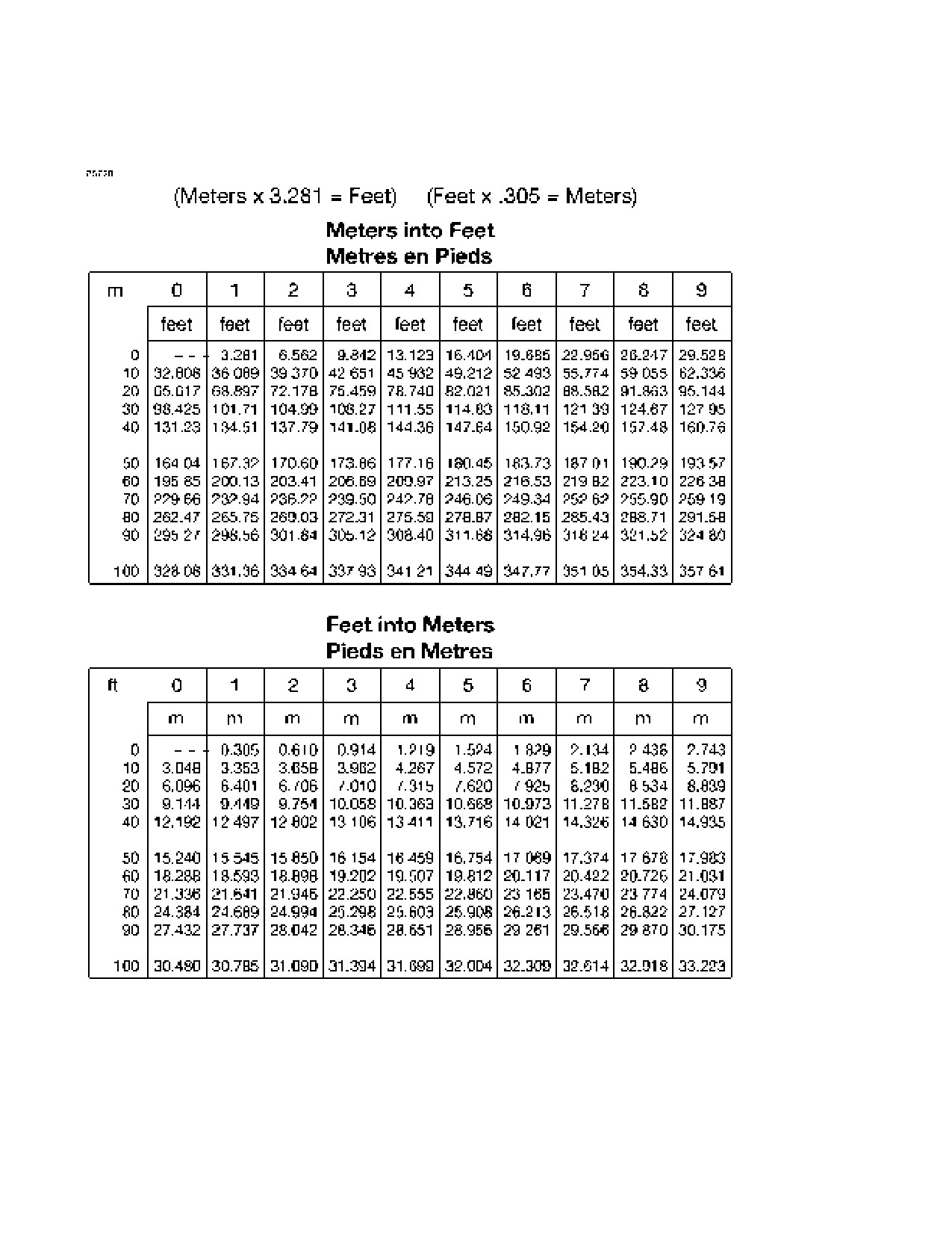
LENGTH CONVERSIONS
Figure 1-3 (Sheet 1 of 4)
1-22
U.S.
208BPHCUS-00
CESSNA
SECTION 1
MODEL 208B (867 SHP)
GENERAL
GARMIN G1000
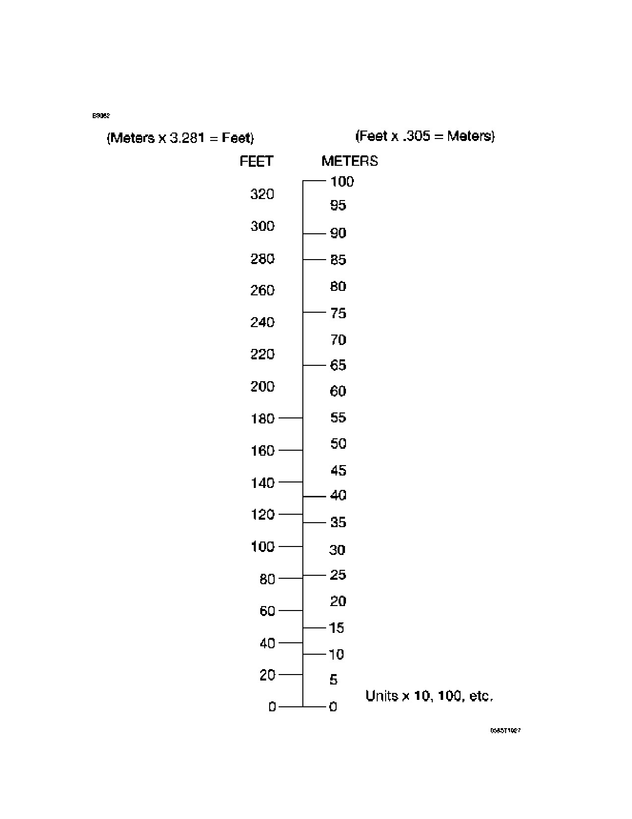
LENGTH CONVERSIONS
Figure 1-3 (Sheet 2)
208BPHCUS-00
U.S.
1-23

SECTION 1
CESSNA
GENERAL
MODEL 208B (867 SHP)
GARMIN G1000
LENGTH CONVERSIONS
Figure 1-3 (Sheet 3)
1-24
U.S.
208BPHCUS-00
CESSNA
SECTION 1
MODEL 208B (867 SHP)
GENERAL
GARMIN G1000
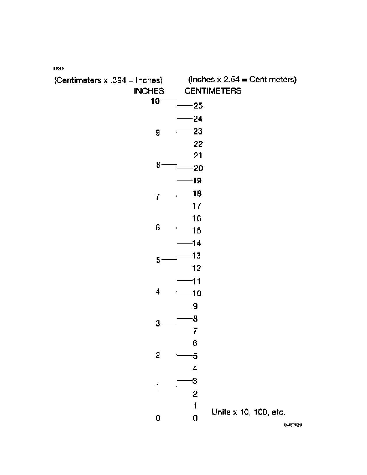
LENGTH CONVERSIONS
Figure 1-3 (Sheet 4)
208BPHCUS-00
U.S.
1-25

SECTION 1
CESSNA
GENERAL
MODEL 208B (867 SHP)
GARMIN G1000
DISTANCE CONVERSIONS
Figure 1-4
1-26
U.S.
208BPHCUS-00

CESSNA
SECTION 1
MODEL 208B (867 SHP)
GENERAL
GARMIN G1000
VOLUME CONVERSIONS
Figure 1-5 (Sheet 1 of 3)
208BPHCUS-00
U.S.
1-27

SECTION 1
CESSNA
GENERAL
MODEL 208B (867 SHP)
GARMIN G1000
VOLUME CONVERSIONS
Figure 1-5 (Sheet 2)
1-28
U.S.
208BPHCUS-00

CESSNA
SECTION 1
MODEL 208B (867 SHP)
GENERAL
GARMIN G1000
VOLUME CONVERSIONS
Figure 1-5 (Sheet 3)
208BPHCUS-00
U.S.
1-29

SECTION 1
CESSNA
GENERAL
MODEL 208B (867 SHP)
GARMIN G1000
TEMPERATURE CONVERSIONS
Figure 1-6
1-30
U.S.
208BPHCUS-00

CESSNA
SECTION 1
MODEL 208B (867 SHP)
GENERAL
GARMIN G1000
PRESSURE CONVERSION
HECTOPASCALS TO INCHES OF MERCURY
Figure 1-7
208BPHCUS-00
U.S.
1-31
SECTION 1
CESSNA
GENERAL
MODEL 208B (867 SHP)
GARMIN G1000
This Page Intentionally Left Blank
1-32
U.S.
208BPHCUS-00
CESSNA
SECTION 2
MODEL 208B (867 SHP)
OPERATING LIMITATIONS
GARMIN G1000
OPERATING LIMITATIONS
TABLE OF CONTENTS
Page
Introduction
2-3
Airspeed Limitations
2-4
Airspeed Indicator Markings
2-5
Powerplant Limitations
2-6
Powerplant Instrument Markings
2-10
Miscellaneous Instrument Markings
. 2-11
Preflight
2-12
Visual and Tactile Check
2-12
Weight Limits
2-13
Center of Gravity Limits
2-13
Maneuver Limits
2-14
Flight Load Factor Limits
2-14
Flight Crew Limits
2-14
Kinds Of Operations Limits
2-15
Kinds of Operations Equipment List
.2-16
Fuel Limitations
2-25
Maximum Operating Altitude Limit
2-28
Outside Air Temperature Limits
2-28
Maximum Passenger Seating Limits
2-28
System and Equipment Limitations
2-29
Flap Limitations
2-29
Standby Electric System
2-29
Aux Audio System
2-29
12V Power System
2-29
Generator Limitations
2-30
G1000 Limitations
2-31
Operational Approvals
2-33
Garmin GFC-700 Automated Flight Control System (AFCS) . . . 2-34
L3 Communications WX 500 Stormscope
2-35
Sirius XM Weather
2-35
Traffic Advisory System (TAS)
2-35
Terrain Awareness and Warning System (TAWS-B)
2-36
(Continued Next Page)
FAA APPROVED
208BPHCUS-00
U.S.
2-1
SECTION 2
CESSNA
OPERATING LIMITATIONS
MODEL 208B (867 SHP)
GARMIN G1000
TABLE OF CONTENTS (Continued)
Page
Other Limitations
2-37
Optional Equipment User’s Guide
2-37
Type II, Type III or Type IV Anti-ice Fluid Takeoff Limitations . . 2-37
Flight in Known Icing Visual Cues
2-38
Placards
2-39
Interior Placards
2-39
Flight Crew Area
2-39
Passenger Area
2-46
Cargo Area
2-48
Exterior Placards
2-51
Wings
2-54
Engine Compartment
2-56
Forward Fuselage
2-59
Aft Fuselage
2-61
FAA APPROVED
2-2
208BPHCUS-00
U.S.
CESSNA
SECTION 2
MODEL 208B (867 SHP)
OPERATING LIMITATIONS
GARMIN G1000
INTRODUCTION
Section
2 includes operating limitations, instrument markings, and
basic placards necessary for the safe operation of the airplane, its
engine, standard/non-standard systems and standard/non-standard
equipment.
WARNING
The limitations included in this section and in
Section
9 have been approved by the Federal
Aviation Administration. Observance of these
operating limitations is required by Federal
Aviation Regulations.
NOTE
• Operation in countries other than the United States may
require observance of other limitations, procedures or
performance data.
• Refer to Section 9, Supplements, of this POH/AFM for
amended operating limitations, operating procedures,
performance data and other necessary information for
airplanes equipped with specific options.
• The airspeeds listed in Figure 2-1, Airspeed Limitations,
and Figure 2-2, Airspeed Indicator Markings, are based
on Airspeed Calibration data shown in Section 5 with the
normal static source. If the alternate static source is
being used, ample margins should be observed to allow
for the airspeed calibration variations between the
normal and alternate static sources as shown in Section
5.
The Cessna Model No. 208B is certificated under FAA Type Certificate
No. A37CE.
FAA APPROVED
208BPHCUS-00
U.S.
2-3

SECTION 2
CESSNA
OPERATING LIMITATIONS
MODEL 208B (867 SHP)
GARMIN G1000
AIRSPEED LIMITATIONS
The airspeed limitations below are based on the maximum gross
takeoff weight of 8807 pounds (3994 kg). The maximum operating
maneuvering speeds (VA) and applicable gross weight limitations are
shown in Figure 2-1.
AIRSPEED LIMITATIONS
Figure 2-1
FAA APPROVED
2-4
208BPHCUS-00
U.S.

CESSNA
SECTION 2
MODEL 208B (867 SHP)
OPERATING LIMITATIONS
GARMIN G1000
AIRSPEED INDICATOR MARKINGS
The airspeed on both the PFD and standby airspeed indicator is
indicated with an airspeed tape with colored bands, refer to Section 7,
Flight Instruments, for more information on airspeed indication. The
indicator markings and their color code significance are shown in
Figure 2-2.
AIRSPEED INDICATOR MARKINGS
* G1000 airspeed indicator only.
Figure 2-2
FAA APPROVED
208BPHCUS-00
U.S.
2-5
SECTION 2
CESSNA
OPERATING LIMITATIONS
MODEL 208B (867 SHP)
GARMIN G1000
POWERPLANT LIMITATIONS
ENGINE
Engine Manufacturer
Pratt & Whitney Canada Inc.
Engine Model Number
PT6A-140
Engine Operating Limits
Refer to Figure 2-3
Fuel Grade and Approved Fuel Additives . .Refer to Fuel Limitations
OIL SPECIFICATION
Oil conforming to Pratt & Whitney Engine Service Bulletin No. 1001,
and all revisions or supplements thereto, must be used. Refer to
Section 8, Airplane Handling, Service and Maintenance, Servicing,
Oil, for a listing of approved oils.
When adding oil, service the engine with the type and viscosity
which is currently being used in the engine.
PROPELLER
Propeller Manufacturer
Hartzell Propeller Inc.
Propeller Model Number
HC-B3TN-3AF/T10890CN-2
Propeller Diameter
Maximum
106 Inches (2.7 m)
Minimum
104 Inches (2.6 m)
Hartzell Propeller Blade Angle at 42-inch Station:
Feathered
78.0 + 1.0°
Low Pitch
8.5 + 0.2°
Maximum Reverse
-21 + 0.5°
(Continued Next Page)
FAA APPROVED
2-6
208BPHCUS-01
U.S.
CESSNA
SECTION 2
MODEL 208B (867 SHP)
OPERATING LIMITATIONS
GARMIN G1000
POWERPLANT LIMITATIONS (Continued)
PROPELLER SYSTEM OPERATING LIMITS
An overspeed governor check shall be performed before the first
flight of the day, after engine control system maintenance, or if
adjustment has been made.
Propeller RPM must be set at
1900 during all instrument
approaches.
ENGINE CONTROL OPERATING LIMITS
Flight operation with the POWER Lever set below the IDLE position
is prohibited. Such positioning may lead to loss of airplane control or
may result in an engine overspeed condition and consequent loss of
engine power.
Operation of the EMERGENCY POWER Lever is prohibited with the
POWER Lever out of the IDLE position.
ENGINE STARTING CYCLE LIMITS
Using the airplane battery, the starting cycle shall be limited to the
following intervals and sequence:
30 seconds ON - 60 seconds OFF,
30 seconds ON - 60 seconds OFF,
30 seconds ON - 30 minutes OFF.
Repeat the above cycle as required.
Using external power, the starting cycle shall be limited to the
following intervals and sequence:
20 seconds ON - 120 seconds OFF,
20 seconds ON - 120 seconds OFF,
20 seconds ON - 60 minutes OFF.
Repeat the above cycle as required.
(Continued Next Page)
FAA APPROVED
208BPHCUS-00
U.S.
2-7

SECTION 2
CESSNA
OPERATING LIMITATIONS
MODEL 208B (867 SHP)
GARMIN G1000
POWERPLANT LIMITATIONS (Continued)
ENGINE OPERATING LIMITS
Figure 2-3 (Sheet 1 of 2)
FAA APPROVED
2-8
208BPHCUS-00
U.S.
CESSNA
SECTION 2
MODEL 208B (867 SHP)
OPERATING LIMITATIONS
GARMIN G1000
POWER PLANT LIMITATIONS (Continued)
ENGINE OPERATING LIMITS (Continued)
NOTE
1.
Per Section 5, Performance, Figure 5-8, Maximum Engine
Torque for Takeoff. Anytime ITT exceeds 825°C, this power
setting is limited to 5 minutes.
2.
For every
10°C
(18°F) below
-30°C
(-22°F) ambient
temperature, reduce maximum allowable Ng by 2.2%.
3.
Normal oil pressure is 85 to 105 PSI at Ng speeds above 72%
with oil temperature between 60° and 70°C (140° and 158°F).
Oil pressures below 80 PSI are undesirable and should be
tolerated only for the completion of the flight, preferably at a
reduced power setting. Oil pressures below normal should be
reported as an engine discrepancy and should be corrected
prior to next flight. Oil pressures below 40 PSI are unsafe and
require that either the engine be shut down or a landing be
made as soon as possible using the minimum power required
to maintain flight.
4.
2090 PROP RPM may be used in an emergency condition,
to complete a flight, and may be utilized at all engine ratings.
5.
Use of Maximum Rated Power Setting is intended for
abnormal situations (e.g., maintain altitude or climb out of
severe icing or windshear conditions).
6.
Maximum transient oil temperature is 104°C for a maximum of
10 minutes.
7.
Per Section 5, Performance, Figures 5-9, Maximum Engine
Torque for Climb.
8.
Per Section 5, Performance, Figure 5-20, Cruise Maximum
Torque with Cargo Pod Installed or Figure
5-37, Cruise
Maximum Torque without Cargo Pod.
9.
Increase Ng to keep idle ITT within limit.
10. Torque must not exceed 2397 foot-pounds. Full 867 SHP
rating is available only at propeller RPM settings of 1900.
11. A transient fluctuation of up to +40 PROP RPM is permitted to
account for power setting accuracy and steady state
fluctuations. Note: Steady state Max N
p setting is 1900 RPM.
Figure 2-3 (Sheet 2)
FAA APPROVED
208BPHCUS-01
U.S.
2-9

SECTION 2
CESSNA
OPERATING LIMITATIONS
MODEL 208B (867 SHP)
GARMIN G1000
POWERPLANT INSTRUMENT MARKINGS
Powerplant instrument markings and their color code significance are
shown in Figure 2-3. Operation with indications in the red range is
prohibited. Avoid operating with indicators in the yellow range.
NOTE
1. Incorporates dynamic redline that moves to display
maximum allowable torque as a function of OAT and
pressure altitude. Takeoff torque is displayed up to 16,000 feet
MSL, while maximum rated torque is displayed at 16,000 feet
MSL and above.
2. Incorporates blue torque bug that moves to compensate for
OAT, pressure altitude and propeller RPM variation.
3. Incorporates red line that moves to compensate for OAT.
100% Ng is 37,468 RPM.
4. Start mode values also valid for OFF mode (red triangle at
1090°C not shown in OFF mode).
5. Start mode is defined as the period between starter
engagement and the point where idle Ng RPM reaches 55%.
6. Run mode is defined as anytime idle Ng RPM is above 55%.
Figure 2-4
FAA APPROVED
2-10
208BPHCUS-01
U.S.

CESSNA
SECTION 2
MODEL 208B (867 SHP)
OPERATING LIMITATIONS
GARMIN G1000
MISCELLANEOUS INSTRUMENT MARKINGS
Power plant instrument markings and their color significance are shown
in Figure 2-5.
NOTE
1. OFF mode is defined as anytime the engine is not running and
the starter has not transitioned to generator mode.
Figure 2-5
FAA APPROVED
208BPHCUS-00
U.S.
2-11
SECTION 2
CESSNA
OPERATING LIMITATIONS
MODEL 208B (867 SHP)
GARMIN G1000
PREFLIGHT
Takeoff is prohibited with any frost, ice, snow, or slush adhering to the
wings, horizontal stabilizer, vertical stabilizer, control surfaces, propeller
blades, and/or engine air inlets.
WARNING
Even small amounts of frost, ice, snow or slush on
the wing may adversely change lift and drag.
Failure to remove these contaminants will degrade
airplane performance and will prevent a safe takeoff
and climb.
VISUAL AND TACTILE CHECK
To assure the absence of frost, a tactile check of the wing leading edge
and upper surface, as specified in Section 4, Normal Procedures, is
required in addition to a visual inspection if the OAT is below 10°C
(50°F). During ground icing conditions, takeoff must be accomplished
within 5 minutes of completing the tactile check unless the airplane is
operated per 14 CFR 135.227(b)(3).
Ground icing conditions are defined as:
1. The OAT is 2°C (36°F) or below and visible moisture is present
(i.e. rain, drizzle, sleet, snow, fog, water is present on the wing,
etc.), or,
2. The OAT is 5°C (41°F) or below and conditions are conducive to
active frost formation
(e.g. clear night with a dew point
temperature/OAT difference of 3°C (5°F) or less).
Takeoff is prohibited if frost, ice or snow may reasonably be expected to
adhere to the airplane between the tactile check and takeoff (e.g. snow
near freezing temperature with no deicing/anti-ice fluid application).
FAA APPROVED
2-12
208BPHCUS-00
U.S.
CESSNA
SECTION 2
MODEL 208B (867 SHP)
OPERATING LIMITATIONS
GARMIN G1000
WEIGHT LIMITS
Maximum Ramp Weight
8842 Pounds (4010 kg)
Maximum Takeoff Weight
8807 Pounds (3994 kg)
Maximum Landing Weight
8500 Pounds (3855 kg)
NOTE
Refer to Section 6, Weight and Balance, Figure 6-11, Cabin
Internal Loading Arrangements, for recommended loading
arrangements.
CENTER OF GRAVITY LIMITS
CENTER OF GRAVITY RANGE
FORWARD WITH OR WITHOUT CARGO POD
185.00 inches (4699 mm) (11.19% MAC) aft of datum at 6500
pounds (2948 kg) or less, with straight line variation to 193.37 inches
(4912 mm) (23.80% MAC) aft of datum at 8000 pounds (3628 kg)
and straight line variation to 199.15 inches (5059 mm) (32.50%
MAC) aft of datum at 8807 pounds (3994 kg).
AFT WITH OR WITHOUT CARGO POD
204.35 inches (5190 mm) (40.33% MAC) aft of datum at all weights
up to 8807 pounds (3994 kg).
REFERENCE DATUM
100 inches (2540 mm) forward of front face of firewall.
MEAN AERODYNAMIC CHORD (MAC)
The leading edge of the MAC is 177.57 inches (4510 mm) aft of the
datum. The MAC length is 66.40 inches (1686 mm).
FAA APPROVED
208BPHCUS-00
U.S.
2-13
SECTION 2
CESSNA
OPERATING LIMITATIONS
MODEL 208B (867 SHP)
GARMIN G1000
MANEUVER LIMITS
This airplane is certificated in the normal category. The normal category
is applicable to aircraft intended for non-aerobatic operations. These
include any maneuvers incidental to normal flying, stalls (except whip
stalls), lazy eights, chandelles, and turns in which the angle of bank is
not more than 60°.
Aerobatic maneuvers, including spins, are not approved.
FLIGHT LOAD FACTOR LIMITS
Maximum Takeoff Weight
8807 Pounds (3994 kg)
*Flaps UP
+3.8g, -1.52g
*Flaps LAND (All Settings)
+2.4g
*The design load factors are 150% of the above, and in all cases,
the structure meets or exceeds design loads.
FLIGHT CREW LIMITS
One pilot required in left seat.
FAA APPROVED
2-14
208BPHCUS-01
U.S.
CESSNA
SECTION 2
MODEL 208B (867 SHP)
OPERATING LIMITATIONS
GARMIN G1000
KINDS OF OPERATIONS LIMITS
The Cessna 208B (867 SHP) equipped with the Garmin G1000 is
approved for day and night, VFR and IFR operations. The airplane may
be approved for flight into known icing conditions when appropriate
equipment is installed. The operating limitation placard reflects the
limits applicable at the time of Airworthiness Certificate issuance.
The minimum equipment for approved operations required under the
Operating Rules are defined by 14 CFR 91 and 14 CFR 135, as
applicable.
The following Kinds of Operations Equipment List (KOEL) identifies the
systems and equipment upon which type certification for each kind of
operation was predicated.
These systems and equipment items must be installed and operable
unless:
1. The airplane is approved to be operated in accordance with a
current Minimum Equipment List (MEL) issued by the FAA.
Or;
2. An alternate procedure is provided in the basic FAA Approved
Airplane Flight Manual for the inoperative state of the listed
equipment and all limitations are complied with.
NOTE
The following systems and equipment list does not included
all equipment required by the 14 CFR Parts 91 and 135
Operating Requirements. It also does not include
components obviously required for the airplane to be
airworthy such as wings, primary flight controls,
empennage, engine, etc.
(Continued Next Page)
FAA APPROVED
208BPHCUS-00
U.S.
2-15
SECTION 2
CESSNA
OPERATING LIMITATIONS
MODEL 208B (867 SHP)
GARMIN G1000
KINDS OF OPERATIONS EQUIPMENT LIST
(Continued Next Page)
FAA APPROVED
2-16
208BPHCUS-01
U.S.
CESSNA
SECTION 2
MODEL 208B (867 SHP)
OPERATING LIMITATIONS
GARMIN G1000
KINDS OF OPERATIONS EQUIPMENT LIST (Continued)
(Continued Next Page)
FAA APPROVED
208BPHCUS-01
U.S.
2-17
SECTION 2
CESSNA
OPERATING LIMITATIONS
MODEL 208B (867 SHP)
GARMIN G1000
KINDS OF OPERATIONS EQUIPMENT LIST (Continued)
(Continued Next Page)
FAA APPROVED
2-18
208BPHCUS-01
U.S.
CESSNA
SECTION 2
MODEL 208B (867 SHP)
OPERATING LIMITATIONS
GARMIN G1000
KINDS OF OPERATIONS EQUIPMENT LIST (Continued)
(Continued Next Page)
FAA APPROVED
208BPHCUS-01
U.S.
2-19
SECTION 2
CESSNA
OPERATING LIMITATIONS
MODEL 208B (867 SHP)
GARMIN G1000
KINDS OF OPERATIONS EQUIPMENT LIST (Continued)
(Continued Next Page)
FAA APPROVED
2-20
208BPHCUS-01
U.S.
CESSNA
SECTION 2
MODEL 208B (867 SHP)
OPERATING LIMITATIONS
GARMIN G1000
KINDS OF OPERATIONS EQUIPMENT LIST (Continued)
(Continued Next Page)
FAA APPROVED
208BPHCUS-01
U.S.
2-21
SECTION 2
CESSNA
OPERATING LIMITATIONS
MODEL 208B (867 SHP)
GARMIN G1000
KINDS OF OPERATIONS EQUIPMENT LIST (Continued)
(Continued Next Page)
FAA APPROVED
2-22
208BPHCUS-01
U.S.
CESSNA
SECTION 2
MODEL 208B (867 SHP)
OPERATING LIMITATIONS
GARMIN G1000
KINDS OF OPERATIONS EQUIPMENT LIST (Continued)
(Continued Next Page)
FAA APPROVED
208BPHCUS-01
U.S.
2-23
SECTION 2
CESSNA
OPERATING LIMITATIONS
MODEL 208B (867 SHP)
GARMIN G1000
KINDS OF OPERATIONS EQUIPMENT LIST (Continued)
FAA APPROVED
2-24
208BPHCUS-01
U.S.
CESSNA
SECTION 2
MODEL 208B (867 SHP)
OPERATING LIMITATIONS
GARMIN G1000
FUEL LIMITATIONS
FUEL CAPACITY
TOTAL FUEL
Both Tanks and Reservoir:
339.1 U.S. Gallons (1283 l)
Both Tanks:
335.6 U.S. Gallons (1270 l)
Each Tank:
167.8 U.S. Gallons (635 l)
TOTAL USABLE FUEL
Both Tanks ON and Reservoir:
335.3 U.S. Gallons (1268 l)
Both Tanks ON:
332.0 U.S. Gallons (1256 l)
Single Tank ON:
165.0 U.S. Gallons (624 l)
TOTAL UNUSABLE FUEL
Both Tanks ON:
3.6 U.S. Gallons (13 l)
Single Tank ON:
2.8 U.S. Gallons (10 l)
Maximum Fuel Imbalance:
200 Pounds (90 kg)
NOTE
To achieve full fuel capacity, fill fuel tank to the top of the
filler neck. Filling fuel tanks to the bottom of the fuel filler
collar
(level with flapper valve) allows space for thermal
expansion and results in a decrease in fuel capacity of 4.0
U.S. gallons (15 l) per side (8.0 U.S. gallons (30 l) total).
The fuel quantity, fuel used and fuel remaining functions of the G1000
are supplemental information only and must be verified by the pilot.
Continuous uncoordinated flight is prohibited if L FUEL LOW, R FUEL
LOW or L-R FUEL LOW annunciator is shown on PFD.
Unusable fuel quantity will continue to increase the longer a significant
sideslip is maintained.
Due to possible fuel starvation, maximum full rudder sideslip duration is
limited to a maximum of three minutes.
FAA APPROVED
208BPHCUS-00
U.S.
2-25

SECTION 2
CESSNA
OPERATING LIMITATIONS
MODEL 208B (867 SHP)
GARMIN G1000
FUEL LIMITATIONS
FUEL GRADE (SPECIFICATION) AND FUEL ADDITIVES
* It is assumed that fuel temperature is the same as Outside Air
Temperature (OAT).
** AN8 is JP-8 fuel with a reduced freeze point specified for
Antarctic operations.
Figure 2-6 (Sheet 1 of 2)
FAA APPROVED
2-26
208BPHCUS-00
U.S.
CESSNA
SECTION 2
MODEL 208B (867 SHP)
OPERATING LIMITATIONS
GARMIN G1000
FUEL LIMITATIONS (Continued)
FUEL GRADE (SPECIFICATION) AND FUEL ADDITIVES
(Continued)
APPROVED FUEL ADDITIVES
One of the following fuel system anti-ice additives must be added to the
fuel as noted at the following concentrations. Use of fuel anti-ice
additives is required if freezing temperatures are expected during any
part of the flight. Refer to Section 8, Airplane Handling, Service and
Maintenance, Servicing, Fuel, for additional information and
recommended blending instructions for approved fuel additives.
NOTE
1.
MIL-DTL-27686 (EGME) or MIL-DTL-85470 (DiEGME), Type:
Anti-Ice Additive, in a concentration of 0.10 to 0.15 percent by
volume.
2.
MIL-DTL-27686 (EGME) or MIL-DTL-85470 (DiEGME), Type:
Anti-Ice Additive, in a concentration of 0.10 to 0.20 percent by
volume.
3.
GOST
8313
(Fluid I), Type: Anti-Ice Additive, in a
concentration of 0.10 to 0.30 percent by volume.
4.
CIS TU6-10-1458 (Fluid I-M), Type: Anti-Ice Additive, in a
concentration of 0.10 to 0.30 percent by volume.
5.
T1301
(SH0396-92), Type: Anti-Ice Additive, in a
concentration of 0.10 to 0.15 percent by volume.
6.
DuPont Stadis 450, Type: Static Dissipator, in a concentration
as required to bring fuel up to 300 conductive units, not to
exceed 1 Parts Per Million (PPM).
7.
SOHIO Biobor JF, Type: Biocide, at a concentration not to
exceed
20 PPM of elemental boron
(270 PPM of total
additive).
8.
Kathon FP, Type: Biocide, at a concentration not to exceed
100 PPM of total additive.
Figure 2-6 (Sheet 2)
FAA APPROVED
208BPHCUS-01
U.S.
2-27
SECTION 2
CESSNA
OPERATING LIMITATIONS
MODEL 208B (867 SHP)
GARMIN G1000
MAXIMUM OPERATING ALTITUDE LIMIT
Non-Icing Conditions
25,000 Feet
Icing Conditions (if equipped)
20,000 Feet
Any conditions with any ice on the airplane
20,000 Feet
OUTSIDE AIR TEMPERATURE LIMITS
Cold Day
-54°C from Sea Level to 25,000 Feet
Hot Day:
Ground Operations
+42°C from Sea Level to 5000 Feet
ISA +37°C above 5000 Feet
Flight Operations
ISA +37°C from Sea Level to 25,000 Feet
Refer to Section 5, Performance, Figure 5-5, ISA Conversion and
Operating Temperature Limits Chart, for a graphical presentation of the
operating air temperature limits.
NOTE
• With both deck skin fans inoperative, ground operations
are limited to +42°C for 30 minutes.
• Ground operations up to +38°C are not time limited with
both deck skin fans inoperative.
MAXIMUM PASSENGER SEATING LIMITS
In the passenger version, up to 11 seats may be installed. The right
front seat may be occupied by either a second crew member or a
passenger. When the right front seat is occupied by a passenger, only
eight seats in the aft cabin can be occupied.
In the cargo version, a maximum of one seat may be installed to the
right of the pilot’s seat for a second crew member or a passenger.
Refer to Section 6, Weight and Balance, Figure 6-11, Cabin Internal
Loading Arrangements, for approved seat locations.
FAA APPROVED
2-28
208BPHCUS-00
U.S.
CESSNA
SECTION 2
MODEL 208B (867 SHP)
OPERATING LIMITATIONS
GARMIN G1000
SYSTEM AND EQUIPMENT LIMITATIONS
FLAP LIMITATIONS
Approved Takeoff Range
UP to TO/APR
Approved Landing Range
UP to LAND
Approved Landing Range in Icing Conditions
UP to TO/APR
STANDBY ELECTRIC SYSTEM
When operating the standby electrical system, the maximum electrical
load is 75 amps from Sea Level to 21,000 feet. To ensure adequate
alternator cooling at higher altitudes, reduce maximum standby
electrical system load 5 amps per 1000 feet above 21,000 feet.
AUX AUDIO SYSTEM
Use of the AUX AUDIO entertainment input is prohibited during takeoff
and landing.
Use of the AUX AUDIO entertainment audio input and Portable
Electronic Devices
(PED), such as cellular telephones, games,
cassette, CD or MP3 players, is prohibited under IFR unless the
operator of the airplane has determined that the use of the Aux Audio
System and the connected PED(s) will not cause interference with the
navigation or communication system of the airplane.
12V POWER SYSTEM
The 12 Volt Power System is limited to a maximum combined current
draw of 10 Amps (120 watts) all locations.
The 12 Volt Power System (12V POWER OUTLET) is not certified for
supplying power to flight-critical communications or navigation devices.
Use of the 12 Volt Power System is prohibited during takeoff and
landing.
Use of the 12 Volt Power System is prohibited under IFR unless the
operator of the airplane has determined that the use of the 12 VDC
power supply and connected PED(s) will not cause interference with
the navigation or communication systems of the airplane.
FAA APPROVED
208BPHCUS-00
U.S.
2-29

SECTION 2
CESSNA
OPERATING LIMITATIONS
MODEL 208B (867 SHP)
GARMIN G1000
SYSTEM AND EQUIPMENT LIMITATIONS (Continued)
GENERATOR LIMITATIONS
Maximum generator load limit is a function of Ng, air conditioning and
bleed air heat position.
ON GROUND
MAXIMUM GENERATOR LOAD - GROUND OPERATIONS
AIR CONDITIONING - OFF,
AIR CONDITIONING - ON,
BLEED AIR HEAT - ON or OFF
BLEED AIR HEAT - OFF
Ng
AMPS
Ng
AMPS
55%
65
55%
35
60%
100
60%
90
65%
135
65%
155
IN FLIGHT
MAXIMUM GENERATOR LOAD - FLIGHT OPERATIONS
AIR CONDITIONING - OFF,
AIR CONDITIONING - ON,
BLEED AIR HEAT - ON or OFF
BLEED AIR HEAT - OFF
Ng
AMPS
Ng
AMPS
65%
125
65%
125
72%
140
72%
170
>80%
200
>80%
200
FAA APPROVED
2-30
208BPHCUS-00
U.S.
CESSNA
SECTION 2
MODEL 208B (867 SHP)
OPERATING LIMITATIONS
GARMIN G1000
SYSTEM AND EQUIPMENT LIMITATIONS (Continued)
G1000 LIMITATIONS
The current Garmin G1000 Cockpit Reference Guide (CRG) Part
Number and System Software Version that must be available to the
pilot during flight are displayed on the MFD AUX group, SYSTEM
STATUS page.
GPS based IFR enroute, oceanic and terminal navigation is prohibited
unless the pilot verifies the currency of the database or verifies each
selected waypoint for accuracy by reference to current approved data.
RNAV/GPS instrument approaches must be accomplished in
accordance with approved instrument approach procedures that are
retrieved from the G1000 navigation database. The G1000 database
must incorporate the current update cycle.
Use of the NAVIGATION MAP page for pilotage navigation is
prohibited. The Navigation Map is intended only to enhance situational
awareness. Navigation is to be conducted using only current charts,
data and authorized navigation facilities.
Navigation using the G1000 is not authorized North of 72° North
latitude or South of
70° South latitude due to unsuitability of the
magnetic fields near the Earth's poles. In addition, operations are not
authorized in the following regions:
1. North of 65° North latitude between longitude 75° W and 120° W
(Northern Canada).
2. North of 70° North latitude between longitude 70° W and 128° W
(Northern Canada).
3. North of 70° North latitude between longitude 85° E and 114° E
(Northern Russia).
4. South of 55° South latitude between longitude 120° E and 165°
E (region south of Australia and New Zealand).
(Continued Next Page)
FAA APPROVED
208BPHCUS-00
U.S.
2-31
SECTION 2
CESSNA
OPERATING LIMITATIONS
MODEL 208B (867 SHP)
GARMIN G1000
SYSTEM AND EQUIPMENT LIMITATIONS (Continued)
G1000 LIMITATIONS (Continued)
Use of the TERRAIN PROXIMITY information for primary terrain
avoidance is prohibited. The Terrain Proximity map is intended only to
enhance situational awareness. It is the pilot’s responsibility to provide
terrain clearance at all times. In addition, Terrain Proximity information
is not available in locations north of 75° North latitude or South of 60°
South latitude due to the absence of terrain data in these geographical
areas.
The COM 1/2 (split COM) function of the Audio Panel is not approved
for use. During COM 1/2 operation, transmission by one crew member
inhibits reception by the other crew member.
Dispatch with GIA1, GIA2, PFD, or MFD cooling advisory message is
prohibited.
Verify the torque gage dynamic redline agrees with the values listed in
Figure 5-8, Maximum Engine Torque For Takeoff, for current altitude
and temperature.
The dynamic redline is a graphical representation of takeoff power
below 16,000 feet MSL and Maximum Rated Power above 16,000 feet
MSL as depicted in Section 5, Performance, Figure 5-8, Maximum
Engine Torque For Takeoff chart and Figure 5-9 Maximum Engine
Torque For Climb. The dynamic redline automatically compensates for
altitude and temperature changes and adjusts displayed takeoff torque
for inertial separator deployment and bleed air heat switch position.
Failure to comply with the dynamic redline indication can result in
accelerated engine wear, unscheduled engine maintenance and
increased operating costs even though no other published engine
limitation has been exceeded.
The maximum cruise torque bug functions of the G1000 engine torque
indicator is advisory information only.
All power settings must be verified by the pilot, refer to Section 5,
Performance, Figure 5-8, Maximum Engine Torque For Takeoff, Figure
5-9, Maximum Engine Torque For Climb and Figure 5-19, Cruise
Performance (with Cargo Pod) or Figure 5-36, Cruise Performance
(without Cargo Pod) for the approved engine power settings.
FAA APPROVED
2-32
208BPHCUS-01
U.S.
CESSNA
SECTION 2
MODEL 208B (867 SHP)
OPERATING LIMITATIONS
GARMIN G1000
SYSTEM AND EQUIPMENT LIMITATIONS (Continued)
G1000 LIMITATIONS (Continued)
OPERATIONAL APPROVALS
The Garmin G1000 GPS receivers are approved under TSO C145c
Class 3. The Garmin G1000 system has been demonstrated capable
of, and has been shown to meet the accuracy requirements for, the
following operations provided it is receiving usable navigation data.
These do not constitute operational approvals.
1. Enroute, terminal, non-precision instrument approach
operations using GPS and WAAS (including GPS, or GPS, and
RNAV approaches), and approach procedures with vertical
guidance (including LNAV/VNAV, LNAV + V, and LPV) within the
U.S. National Airspace System in accordance with AC 20-138C.
2. As a required Long Range Navigation (LRN) system for use in
the following types of airspace when used in conjunction with
Garmin WAAS Fault Detection/Exclusion Prediction Program,
part number 006-A0154-01 or later approved version:
a. Oceanic/Remote - RNP-10 (per FAA AC 20-138C, FAA
Order
8400-12C, and FAA Order
8900.1). Both GPS
receivers are required to be operating and receiving usable
signals except for routes requiring only one Long Range
Navigation (LRN) sensor.
NOTE
Each display computes an independent navigation solution
based on the on-side GPS sensor. However, either display
will automatically revert to the cross-side sensor if the on-
side sensor fails or if the cross-side sensor is determined to
be more accurate. A BOTH ON GPS1 or BOTH ON GPS2
message does not necessarily mean that one GPS has
failed. Refer to the MFD AUX-GPS STATUS page to
determine the status of the unused GPS.
b. North Atlantic
(NAT) Minimum Navigational Performance
Specifications (MNPS) Airspace per AC 91-49 Chg 1 and
AC 120-33. Both GPS receivers are required to be operating
and receiving usable signals except for routes requiring only
one Long Range Navigation sensor.
c. Enroute and Terminal including RNP5/BRNAV and PRNAV
(RNP-1) - In accordance with JAA TGL-10, ACJ 20X4, AC
90-96A, and AC 90-100A, provided the FMS is receiving
usable navigation information from one or more GPS
receivers.
FAA APPROVED
208BPHCUS-00
U.S.
2-33
SECTION 2
CESSNA
OPERATING LIMITATIONS
MODEL 208B (867 SHP)
GARMIN G1000
SYSTEM AND EQUIPMENT LIMITATIONS (Continued)
G1000 LIMITATIONS (Continued)
GARMIN GFC 700 AUTOMATED FLIGHT CONTROL SYSTEM
(AFCS)
1.
The GFC
700 AFCS preflight test must be successfully
completed prior to use of the autopilot, flight director or manual
electric trim.
2.
A pilot, with the seat belt fastened, must occupy the left pilot’s
seat during all autopilot operations.
3.
The autopilot and yaw damper must be off during all takeoff and
landings.
4.
Autopilot maximum engagement speed
175 KIAS
Autopilot minimum engagement speed
80 KIAS
Electric Trim maximum operating speed
175 KIAS
5.
The autopilot must be disengaged below 200 feet AGL during
approach operations and below 800 feet AGL during all other
operations.
6.
ILS approaches using the autopilot/flight director are limited to
Category I approaches only.
7.
Raw data ILS approaches below 400 feet AGL are prohibited.
8.
Use of the autopilot is prohibited when the audio panel is
inoperative, since the aural alert will not be provided when
autopilot is disengaged.
9.
When conducting a missed approach, use of the autopilot is
prohibited until a rate of climb is established that will meet all
altitude requirements of the missed approach procedure.
FAA APPROVED
2-34
208BPHCUS-00
U.S.
CESSNA
SECTION 2
MODEL 208B (867 SHP)
OPERATING LIMITATIONS
GARMIN G1000
SYSTEM AND EQUIPMENT LIMITATIONS (Continued)
G1000 LIMITATIONS (Continued)
L3 COMMUNICATIONS WX 500 STORMSCOPE (if installed)
Use of the WEATHER MAP (WX-500 Stormscope) for hazardous
weather (thunderstorm) penetration is prohibited. LTNG information on
the NAVIGATION MAP or WEATHER MAP is approved only as an aid
to hazardous weather avoidance, not penetration. The WX-500
Stormscope user’s guide should be available to the pilot during flight.
SIRIUS XM WEATHER (if installed)
Use of the XM data link weather information for maneuvering in, near or
around areas of hazardous weather is prohibited. Information
contained within XM data link weather products may not accurately
depict current weather conditions.
Do not use the indicated XM data link weather product age to
determine the age of the weather information shown by the XM data
link weather product. Due to time delays inherent in gathering and
processing weather data for XM data link transmission, the weather
information shown by the XM data link weather product may be
significantly older than the indicated weather product age.
TRAFFIC ADVISORY SYSTEM (TAS) (if installed)
Use of the TRAFFIC MAP to maneuver the airplane to avoid traffic is
prohibited. The Traffic Advisory System (TAS) is intended for advisory
use only. TAS is intended only to help the pilot to visually locate traffic.
It is the responsibility of the pilot to see and maneuver to avoid traffic.
TAS is unable to detect any intruding aircraft without an operating
transponder. TAS can detect and track aircraft with either an ATCRBS
(operating in Mode A or C) or Mode S transponders.
ATC procedures and the “see and avoid concept” will continue to be the
primary means of aircraft separation. However, if communication is lost
with ATC, TAS adds a significant backup for collision avoidance.
FAA APPROVED
208BPHCUS-00
U.S.
2-35
SECTION 2
CESSNA
OPERATING LIMITATIONS
MODEL 208B (867 SHP)
GARMIN G1000
SYSTEM AND EQUIPMENT LIMITATIONS (Continued)
G1000 LIMITATIONS (Continued)
TERRAIN AWARENESS AND WARNING SYSTEM (TAWS-B) (if
installed)
Use of the Terrain Awareness and Warning System (TAWS-B) to
navigate to avoid terrain or obstacles is prohibited. TAWS-B is only
approved as an aid to help the pilot to see-and-avoid terrain or
obstacles.
TAWS-B must be inhibited when landing at a location not included in
the airport database.
Use of TAWS-B is prohibited when operating using the QFE altimeter
setting (altimeter indicates 0 feet altitude when the airplane is on the
runway).
The pilot is authorized to deviate from the current ATC clearance only
to the extent necessary to comply with TAWS-B warnings.
The geographic area of the TAWS-B database must match the
geographic area in which the airplane is being operated.
TAWS-B is not available in locations north of 75° North latitude or south
of
60° South latitude due to the absence of terrain data in these
geographical areas.
FAA APPROVED
2-36
208BPHCUS-00
U.S.
CESSNA
SECTION 2
MODEL 208B (867 SHP)
OPERATING LIMITATIONS
GARMIN G1000
OTHER LIMITATIONS
OPTIONAL EQUIPMENT USER’S GUIDE
The pilot is responsible for ensuring the appropriate user’s guide(s) for
all optional equipment installed in the airplane is accessible to the pilot
in flight.
TYPE II, TYPE III OR TYPE IV ANTI-ICE FLUID TAKEOFF
LIMITATIONS
FLAP LIMITATIONS
Takeoff Flaps Setting
UP
AIRSPEED LIMITATIONS
Takeoff Rotation Speed
83 KIAS
FAA APPROVED
208BPHCUS-00
U.S.
2-37
SECTION 2
CESSNA
OPERATING LIMITATIONS
MODEL 208B (867 SHP)
GARMIN G1000
OTHER LIMITATIONS (Continued)
FLIGHT IN KNOWN ICING VISUAL CUES
As Required by AD 96-09-15, Paragraph (a) (1)
WARNING
Severe icing may result from environmental
conditions outside of those for which the airplane
is certificated. Flight in freezing rain, freezing
drizzle, or mixed icing conditions
(supercooled
liquid water and ice crystals) may result in ice
build-up on protected surfaces exceeding the
capability of the ice protection system, or may
result in ice forming aft of the protected surfaces.
This ice may not be shed using the ice protection
systems, and may seriously degrade the
performance and controllability of the airplane.
During flight, severe icing conditions that exceed those for which the
airplane is certificated shall be determined by the following visual cues.
If one or more of these visual cues exists, immediately request priority
handling from Air Traffic Control to facilitate a route or an altitude
change to exit the icing conditions.
1. Unusually extensive ice is accreted on the airframe in areas not
normally observed to collect ice.
2. Accumulation of ice on the upper or lower surface of the wing aft
of the protected area.
3. Heavy ice accumulations on the windshield, or when ice forms aft
of the curved sections on the windshield.
4. Ice forms aft of the protected surfaces of the wing struts.
Since the autopilot may mask tactile cues that indicate adverse
changes in handling characteristics, use of the autopilot is prohibited
when any of the visual cues specified above exist, or when unusual
lateral trim requirements or autopilot trim warnings are encountered
while the airplane is in icing conditions.
FAA APPROVED
2-38
208BPHCUS-00
U.S.

CESSNA
SECTION 2
MODEL 208B (867 SHP)
OPERATING LIMITATIONS
GARMIN G1000
PLACARDS
WARNING
The following information must be displayed in the
form of composite or individual placards. As a
minimum, the exact wording of these placards is
required as specified in this section. Placard
wording can be from part numbered placards
obtained from Cessna Aircraft Company or
equivalent placards installed by an approved repair
station in accordance with normal maintenance
practices/procedures.
INTERIOR PLACARDS
FLIGHT CREW AREA
In full view of the pilot on the sunvisor or windshield trim on airplanes
not equipped for flight into known icing:
(Continued Next Page)
FAA APPROVED
208BPHCUS-00
U.S.
2-39
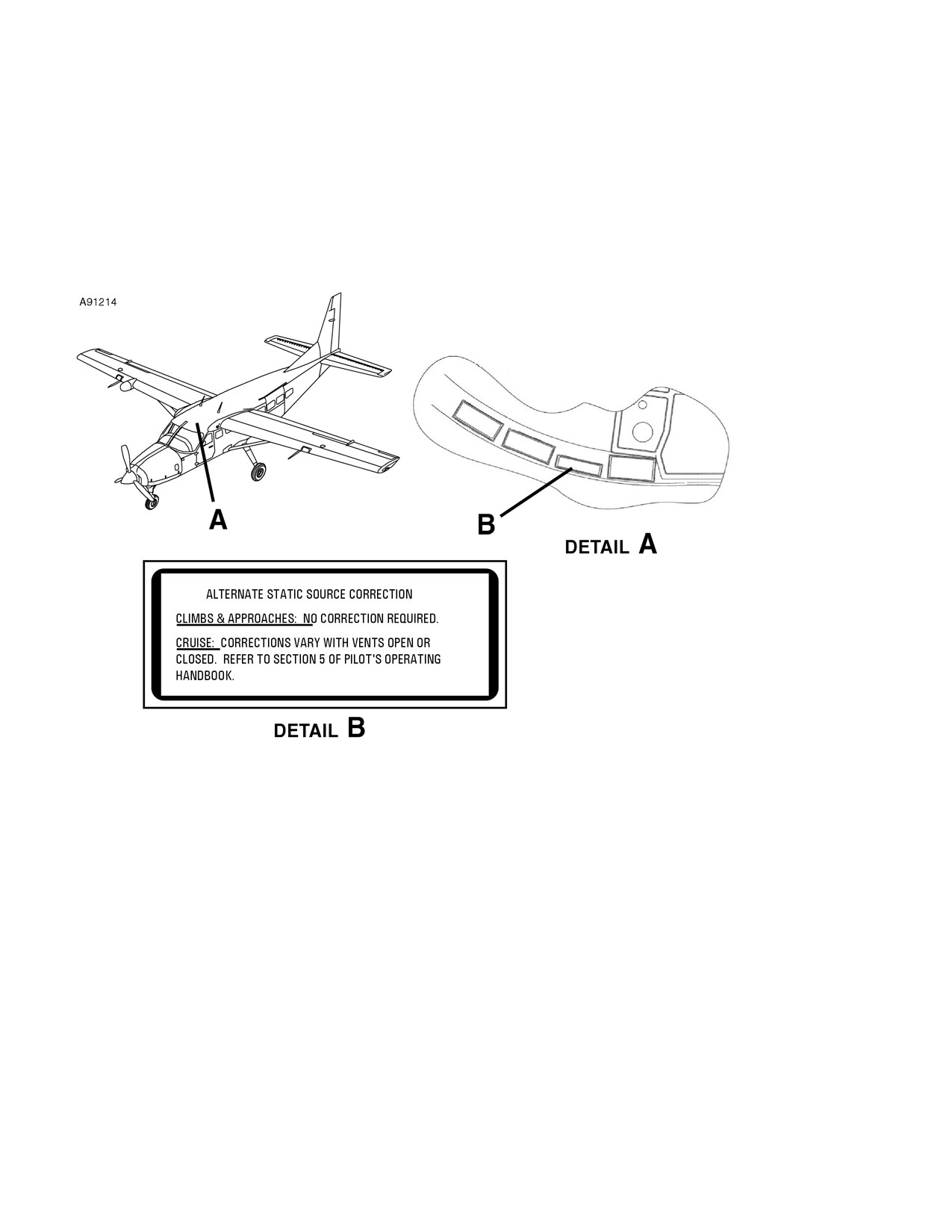
SECTION 2
CESSNA
OPERATING LIMITATIONS
MODEL 208B (867 SHP)
GARMIN G1000
PLACARDS (Continued)
INTERIOR PLACARDS (Continued)
FLIGHT CREW AREA (Continued)
In full view of the pilot on the sunvisor or windshield trim:
(Continued Next Page)
FAA APPROVED
2-40
208BPHCUS-00
U.S.
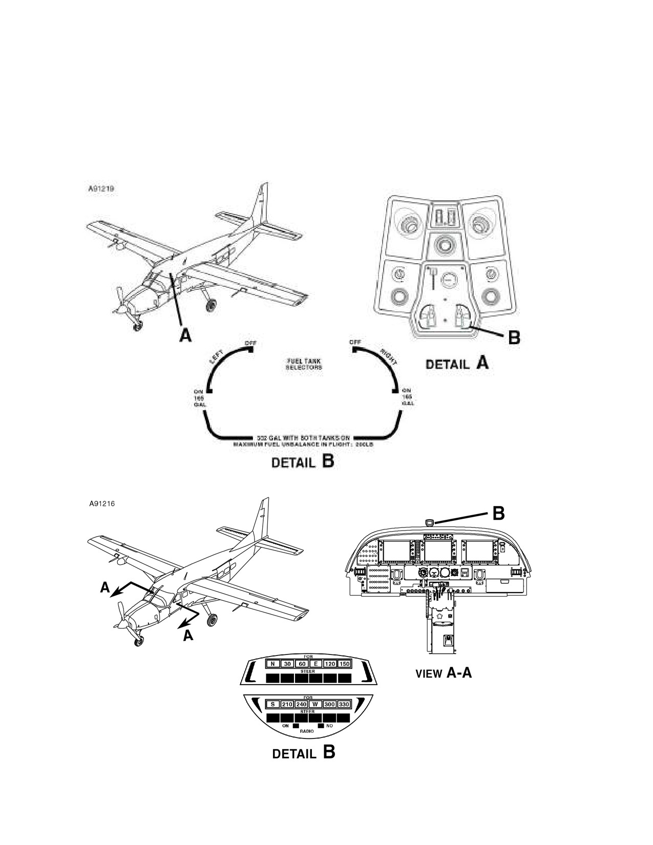
CESSNA
SECTION 2
MODEL 208B (867 SHP)
OPERATING LIMITATIONS
GARMIN G1000
PLACARDS (Continued)
INTERIOR PLACARDS (Continued)
FLIGHT CREW AREA (Continued)
On overhead panel adjacent to fuel tank selectors:
Located on magnetic compass:
(Continued Next Page)
FAA APPROVED
208BPHCUS-00
U.S.
2-41

SECTION 2
CESSNA
OPERATING LIMITATIONS
MODEL 208B (867 SHP)
GARMIN G1000
PLACARDS (Continued)
INTERIOR PLACARDS (Continued)
FLIGHT CREW AREA (Continued)
Above left side PFD:
On instrument panel below standby instruments:
(Continued Next Page)
FAA APPROVED
2-42
208BPHCUS-00
U.S.

CESSNA
SECTION 2
MODEL 208B (867 SHP)
OPERATING LIMITATIONS
GARMIN G1000
PLACARDS (Continued)
INTERIOR PLACARDS (Continued)
FLIGHT CREW AREA (Continued)
On pedestal adjacent to wing flap position indicator:
On pedestal below the power lever:
(Continued Next Page)
FAA APPROVED
208BPHCUS-00
U.S.
2-43

SECTION 2
CESSNA
OPERATING LIMITATIONS
MODEL 208B (867 SHP)
GARMIN G1000
PLACARDS (Continued)
INTERIOR PLACARDS (Continued)
FLIGHT CREW AREA (Continued)
On left and right lower sidewall below and forward of instrument
panel:
On the control lock:
(Continued Next Page)
FAA APPROVED
2-44
208BPHCUS-00
U.S.

CESSNA
SECTION 2
MODEL 208B (867 SHP)
OPERATING LIMITATIONS
GARMIN G1000
PLACARDS (Continued)
INTERIOR PLACARDS (Continued)
FLIGHT CREW AREA (Continued)
Adjacent to left crew door inside door handle:
(Continued Next Page)
FAA APPROVED
208BPHCUS-00
U.S.
2-45

SECTION 2
CESSNA
OPERATING LIMITATIONS
MODEL 208B (867 SHP)
GARMIN G1000
PLACARDS (Continued)
INTERIOR PLACARDS (Continued)
PASSENGER AREA
Adjacent to upper passenger door inside door handle (Passenger
version only):
Adjacent to the interior door handle of lower passenger door
(Passenger version only):
(Continued Next Page)
FAA APPROVED
2-46
208BPHCUS-00
U.S.

CESSNA
SECTION 2
MODEL 208B (867 SHP)
OPERATING LIMITATIONS
GARMIN G1000
PLACARDS (Continued)
INTERIOR PLACARDS (Continued)
PASSENGER AREA (Continued)
On right sidewall aft of lower passenger door below window trim
(Passenger version only):
Adjacent to upper cargo door interior door handle
(Passenger
version only):
(Continued Next Page)
FAA APPROVED
208BPHCUS-00
U.S.
2-47
//////////////////////////////////////////