CESSNA 172R NAV I/NAV II Skyhawk MODEL 172R. Information Manual (2016) - page 3
SECTION 9 - SUPPLEMENTS
CESSNA
SUPPLEMENT 18
MODEL 172R
NAV I/NAV II
UKRAINIAN CERTIFIED AIRPLANES
GENERAL
This supplement must be placed in Section 9 of the basic Pilot’s
Operating Handbook and FAA Approved Airplane Flight Manual for
Ukrainian Certified Airplanes. The information contained herein
supplements the information of the basic Pilot’s Operating Handbook
and FAA Approved Airplane Flight Manual. Limitations, procedures,
and performance found in this supplement supersedes those found in
the basic Pilot’s Operating Handbook and FAA Approved Airplane
Flight Manual. For limitations, procedures, and performance
information not contained in this supplement, consult the basic Pilot’s
Operating Handbook and FAA Approved Airplane Flight Manual.
NOTE
In Ukraine, FAA operating rules (i.e., 14 CFR Part 91 and
14 CFR Part 135) are not applicable. The airplane must be
equipped and operated in accordance with applicable
Ukraine operational requirements.
FAA APPROVED
S18-4
U.S.
172RPHUS-S18-00
CESSNA
SECTION 9 - SUPPLEMENTS
MODEL 172R
SUPPLEMENT 18
NAV I/NAV II
OPERATING LIMITATIONS
The following Limitations supersede and/or are in addition to the
Limitations set forth in the basic Pilot’s Operating Handbook and FAA
Approved Airplane Flight Manual:
Minimum Flight Crew:
One (1) Pilot (flying from left seat)
Maximum Number Of Seats:
Four (4)
Maximum Number Of Passengers:
Three (3) Passengers
The Nav I/Nav II Avionics Option equipped with the KAP 140 Single or
2 Axis Autopilot is approved for Category I ILS approach operations
only.
The Global Positioning Satellite (GPS) system is not approved for
approach.
Operation over water beyond the Maximum Glide distance from shore
is prohibited (Refer to the POH/AFM, Section 3, Figure 3-1).
A Flight Data Recorder (FDR) must be installed and operational for all
commercial transportation operations.
A portable COSPAS-SARSAT (406MHz) Emergency Radio Beacon
must be carried and operational for all operations over areas that are
difficult to access, certain regions that are rarely populated and when
flying over large bodies of water.
A HF radio must be installed and operational if airplane operates in
areas where communication through VHF radio stations cannot be
performed.
FAA APPROVED
172RPHUS-S18-00
U.S.
S18-5
SECTION 9 - SUPPLEMENTS
CESSNA
SUPPLEMENT 18
MODEL 172R
NAV I/NAV II
OPERATING LIMITATIONS (Continued)
FUEL LIMITATIONS
Approved Fuels:
100LL (ASTM-D910)
100 (Formerly 100/130) (ASTM-D910)
B91/115 (GOST 1012-72)*
NOTE
* If Russian B91/115 fuel is used, the airplane must be
equipped with either float type or Gen 3.0 fuel level
senders.
See the latest revision of Lycoming Service Instruction No.1070 for
approved fuel grades.
Fuels must contain an anti-icing fuel additive (Isopropyl Alcohol or
DiEGME) in concentrations mixed as noted in Section 8 of the POH/
AFM.
MAXIMUM APPROVED OPERATING ALTITUDE
The maximum operating barometric altitude is limited to the following:
With Passengers
3000 m (9800 feet)
Flight Crew Only (30 Minutes Maximum)
3600 m (11,800 feet)
OUTSIDE AIR TEMPERATURE LIMITS
Ground operations limits for a cold day:
Minus 40°C
Ground operations limits for a hot day:
+40°C
(Continued Next Page)
FAA APPROVED
S18-6
U.S.
172RPHUS-S18-00
CESSNA
SECTION 9 - SUPPLEMENTS
MODEL 172R
SUPPLEMENT 18
NAV I/NAV II
OPERATING LIMITATIONS (Continued)
TAXI OPERATIONAL LIMITS
Uncontaminated paved taxiway:
• Maximum wind velocity while taxiing:
14 m/s (27 Knots)
Paved taxiway contaminated with precipitation:
• Maximum wind velocity while taxiing:
3 m/s (5 Knots)
Refer to Section 4 of the POH/AFM for additional information on taxiing.
TAKEOFF AND LANDING OPERATIONAL LIMITS
Maximum Takeoff and Landing Altitude:
2438 m (8000 feet)
Maximum Headwind Velocity:
14 m/s (27 Knots)
Maximum Tailwind Velocity:
5 m/s (10 Knots)
Maximum crosswind velocity on
uncontaminated paved runway:
7m/s (15 Knots)
ALLOWABLE RUNWAY SURFACE CONDITIONS
1. Uncontaminated runway with paved surface.
2. Paved runway contaminated with precipitation (average depth
and types):
a. Water, less that 10.0 mm.
b. Slush, less than 10.0 mm.
c. Loose snow less than 30.0 mm.
3. Unpaved runway
a. Surface hardness not less than 7 kg/cm2 with wheel fairings
installed.
b. Surface hardness not less than 5 kg/cm2 with wheel fairings
removed.
c. Landing on contaminated unpaved runways is prohibited.
Operating with the landing gear fairings removed is recommended on
wet or unpaved runways when temperatures are near or below
freezing.
(Continued Next Page)
FAA APPROVED
172RPHUS-S18-00
U.S.
S18-7
SECTION 9 - SUPPLEMENTS
CESSNA
SUPPLEMENT 18
MODEL 172R
NAV I/NAV II
OPERATING LIMITATIONS (Continued)
TAKEOFF AND LANDING OPERATIONAL LIMITS
(Continued)
MAXIMUM CROSSWIND ON CONTAMINATED RUNWAYS
Contaminated paved runways with:
Water, less than 10.0 mm
3 m/s (5 Knots)
Slush, less than 10.0 mm
3 m/s (5 Knots)
Loose snow, less than 30.0 mm
3 m/s (5 Knots)
Paved runway with less than 3 mm of water, snow or slush and braking
coefficient of friction(μ) of:
μ=0.3 (poor braking)
3 m/s (5 Knots)
μ=0.4 (average braking)
5 m/s (9 Knots)
μ=0.5 (good braking, dry or
equivalent to dry runway)
7 m/s (15 Knots)
NOTE
• For intermediate values of coefficient of friction (ȝ),
crosswind is to be estimated by interpolation.
• Operation is prohibited on a runway covered with ice at a
coefficient of friction ȝ < 0.3.
FAA APPROVED
S18-8
U.S.
172RPHUS-S18-00

CESSNA
SECTION 9 - SUPPLEMENTS
MODEL 172R
SUPPLEMENT 18
NAV I/NAV II
OPERATING LIMITATIONS (Continued)
REQUIRED PLACARDS AND MARKINGS
Located adjacent to the left and right exterior door handles. Placard
is approximately 11.33 inches (28.78 cm) by 4.66 inches (11.84 cm)
with 1.00 inch (2.54 cm) red letters on a white background:
FAA APPROVED
172RPHUS-S18-00
U.S.
S18-9
SECTION 9 - SUPPLEMENTS
CESSNA
SUPPLEMENT 18
MODEL 172R
NAV I/NAV II
EMERGENCY PROCEDURES
FORCED LANDINGS
If all attempts to restart the engine fail and a forced landing is imminent,
select a suitable field and prepare for the landing as discussed under
the Emergency Landing Without Engine Power checklist. Transmit
Mayday message on 121.5 MHz giving location, intentions and squawk
7700.
Before attempting an off airport landing with engine power available,
one should fly over the landing area at a safe, but low altitude, to
inspect the terrain for obstructions and surface conditions, proceeding
as discussed in the Precautionary Landing With Engine Power
checklist.
Prepare for ditching by securing or jettisoning heavy objects located in
the baggage area and collect folded coats for protection of occupants'
face at touchdown. Transmit Mayday messages on 121.5 MHz giving
location, intentions and squawk 7700. Avoid a landing flare because of
the difficulty in judging height over a water surface. The checklist
assumes the availability of power to make a precautionary water
landing. If power is not available, use of the airspeeds noted with
minimum flap extension will provide a more favorable attitude for a
power off ditching.
In a forced landing situation, do not turn off the MASTER switch or
AVIONICS switch until a landing is assured. Premature deactivation of
the switches will disable all airplane electrical systems.
FAA APPROVED
S18-10
U.S.
172RPHUS-S18-00
CESSNA
SECTION 9 - SUPPLEMENTS
MODEL 172R
SUPPLEMENT 18
NAV I/NAV II
NORMAL PROCEDURES
BEFORE STARTING ENGINE
NOTE
• When flight over water surface is intended, the airplane
must be equipped with emergency ditching flotation
equipment as required by Operation Regulations.
• Life vests must be put on before boarding the airplane.
COLD SOAK
If extended exposure to cold weather is expected, refer to Maintenance
Manual, Model 172 Series 1996 and On, Chapter 12 Servicing, Section
12-30-00 Unscheduled Servicing-Description and Operation,
paragraph 3 Cold Soak, for procedures to prepare the airplane for cold
soak.
After extended exposure, for more than two hours, at temperatures
colder than Minus -10°C (14°F), refer to Maintenance Manual, Model
172 Series 1996 and On, Chapter 12 Servicing, Section 12-30-00
Unscheduled Servicing-Description and Operation, paragraph 3 Cold
Soak, for procedures of an airplane for preparing the airplane for flight.
Cold temperatures will affect control cable tension. See Chapter 27 of
the Maintenance Manual for flight control cable tensions. See Chapter
12 of the Maintenance Manual for information on lubrication and
greasing of moving parts. See Section 8 of the POH/AFM for correct
engine oil viscosity. See paragraphs on Cold Weather Operation in
Section 4 of the POH/AFM for additional information on procedures for
operating the airplane in cold temperatures.
When the outside temperature is less than Minus 34ºC, the airplane
batteries should be removed and stored in the warm conditions.
(Continued Next Page)
FAA APPROVED
172RPHUS-S18-00
U.S.
S18-11
SECTION 9 - SUPPLEMENTS
CESSNA
SUPPLEMENT 18
MODEL 172R
NAV I/NAV II
NORMAL PROCEDURES (Continued)
COLD SOAK (Continued)
Engine must be preheated before starting if engine temperature is less
than Minus 6°C. Refer to Lycoming Service Instruction No. 1505 for
recommendation of an engine preheating procedures.
When the outside temperature is less than
0°C, moisture from
combustion can freeze on the engine spark plugs if the engine does not
continue to operate after it is started. This will prevent the engine from
starting again. Preheat the engine to more than 0°C before starting the
engine again.
Preheat the engine by directing warm air into the engine cowling inlets
behind the propeller. The temperature of the preheating air should not
be more than 120°C to prevent damage to the exterior paint. Open
flames are prohibited near the airplane.
Before takeoff, preheat the airplane cabin to more than Minus 30°C for
correct operation of the standby altimeter. If there is no warning that an
instrument is operating incorrectly, all other instruments will operate
down to the minimum temperature of the airplane.
Before operating the airplane, it is recommended to heat the cabin to a
comfortable temperature for the cabin occupants.
FAA APPROVED
S18-12
U.S.
172RPHUS-S18-00
CESSNA
SECTION 9 - SUPPLEMENTS
MODEL 172R
SUPPLEMENT 18
NAV I/NAV II
PERFORMANCE
TAKEOFF DISTANCE
The takeoff distance on a paved runway with no more than 3 mm of
precipitation is equal to dry runway takeoff distance.
The takeoff distance on a paved runway with precipitation greater than
3 mm is 20% greater than the dry runway takeoff distance.
LANDING DISTANCE
DRY RUNWAY - BASIC AIRFIELD
To determine the required landing distance for Ukrainian Certified
Airplanes on a dry paved runway, the dry runway landing distance listed
in Section 5, Performance, Short Field Landing Distance, Figure 5-11,
of the U.S. POH must be multiplied by 1.67.
DRY RUNWAY - DIVERSION OR ALTERNATE AIRFIELD
To determine the required landing distance for Ukrainian Certified
Airplanes on a dry paved runway, the dry runway landing distance listed
in Section 5, Performance, Short Field Landing Distance, Figure 5-11,
of the U.S. POH must be multiplied by 1.43.
CONTAMINATED RUNWAY
To determine the required landing distance for Ukrainian Certified
Airplanes on a contaminated paved runway, the Ukrainian-Factored dry
runway landing distance must be multiplied by 1.43.
WET RUNWAY
To determine the required landing distance for Ukrainian Certified
Airplanes on a wet paved runway, the Ukrainian-Factored dry runway
landing distance must be multiplied by 1.15.
For unpaved runway landing distance, refer to Section 5, Performance,
Short Field Landing Distance, Figure 5-11, of the U.S. POH for the
correction applied to grass runway landing distance.
FAA APPROVED
172RPHUS-S18-00
U.S.
S18-13/S18-14
CESSNA
SECTION 9 - SUPPLEMENTS
MODEL 172R
SUPPLEMENT 18
NAV I/NAV II
LOG OF UKRAINE APPROVED SUPPLEMENTS
The following list contains Ukrainian SAA accepted supplements. Refer
to Log of Approved Supplements in the basic Pilot's Operating
Handbook and FAA Approved Airplane Flight Manual for revision
status.
Supplement
Name
Equipment
Number
Installed
1
Bendix/King KX 155A VHF NAV/COMM
with KI 208 or KI 209A Indicator Head
_____________
2
Bendix/King KT
76C Transponder with
Blind Encoder
_____________
3
Bendix/King KMA 26 Audio Selector Panel_____________
4
Pointer Model 3000-11 or Model 4000-11
Emergency Locator Transmitter (ELT)
_____________
5
Bendix/King KLN 89B Global Positioning
System (GPS)
_____________
6
Bendix/King KR 87 Automatic Direction
Finder (ADF)
_____________
7
Bendix/King KAP 140 Single Axis Autopilot_____________
8
Winterization Kit
_____________
9
Davtron Model 803 Clock/OAT
_____________
10
Bendix/King KLN
89 Global Positioning
System (GPS)
_____________
11
Reserved
12
Reserved
13
Bendix/King KCS-55A Slaved Compass
System with KI-525A Horizontal Situation
Indicator (HSI)
_____________
14
Reserved
15
Bendix/King KAP 140 2 Axis Autopilot
_____________
16
Bendix/King KT 73 Mode S Transponder
_____________
(Continued Next Page)
FAA APPROVED
172RPHUS-S18-00
U.S.
S18-15
SECTION 9 - SUPPLEMENTS
CESSNA
SUPPLEMENT 18
MODEL 172R
NAV I/NAV II
LOG OF UKRAINE APPROVED SUPPLEMENTS
Supplement
Name
Equipment
Number
Installed
17
Reserved
18
Ukrainian Certified Airplanes
_____________
19
Bendix/King KLN
94 Global Positioning
System
_____________
20
Bendix/King KMA 28 Audio Selector Panel_____________
21
Bendix/King KMD
550 Multi-Function
Display
_____________
22
12 Volt Cabin Power System
_____________
23
Reserved
24
Astrotech Model TC-2 Clock/OAT/Volt
Indicator
_____________
25
Bendix/King KX 165A VHF NAV/COM
_____________
26
Bendix/King KDR 510 Flight Information
Services (FIS)
_____________
FAA APPROVED
S18-16
U.S.
172RPHUS-S18-00
Pilot's Operating Handbook and
FAA Approved Airplane Flight Manual
CESSNA MODEL 172R
AIRPLANES 17280852
AND ON
SUPPLEMENT 19
BENDIX/KING KLN 94
GLOBAL POSITIONING SYSTEM (IFR)
SERIAL NO.
REGISTRATION NO.
This supplement must be inserted into Section
9 of the Pilot's Operating
Handbook and FAA Approved Airplane Flight Manual when the Global Positioning
System is installed.
FAA APPROVAL
Date: 14 December 2000
Member of GAMA
6 November 2000
COPYRIGHT ” 2000
CESSNA AIRCRAFT COMPANY
WICHITA, KANSAS, USA
Revision 4 - 4 June 2003
172RPHUS-S19-04
S19-1
SECTION 9 - SUPPLEMENTS
CESSNA
SUPPLEMENT 19 - FAA APPROVED
MODEL 172R
SUPPLEMENT 19
BENDIX/KING KLN 94
GLOBAL POSITIONING SYSTEM (IFR)
Use the Log of Effective Pages to determine the current status of
this supplement. Pages affected by the current revision are
indicated by an asterisk (*) preceding the page number.
Supplement Status
Date
Original Issue
6 November 2000
Revision 1
18 December 2000
Revision 2
30 December 2000
Revision 3
22 January 2001
Revision 4
4 June 2003
LOG OF EFFECTIVE PAGES
Page
Page
Revision
Number
Status
Number
* S19-1 thru S19-20
Revised
Revision 4
* S19-21/S19-22
Added
Revision 4
S19-2
Revision 4
CESSNA
SECTION 9 - SUPPLEMENTS
MODEL 172R
SUPPLEMENT 19 - FAA APPROVED
SUPPLEMENT 19
BENDIX/KING KLN 94
GLOBAL POSITIONING SYSTEM (IFR)
SERVICE BULLETIN CONFIGURATION LIST
The following is a list of Service Bulletins that are applicable to
the operation of the airplane, and have been incorporated into
this supplement. This list contains only those Service Bulletins
that are currently active.
Airplane
Serial
Revision
Incorporated
Number Title
Effectivity
Incorporation
In Airplane
Revision 4
S19-3
SECTION 9 - SUPPLEMENTS
CESSNA
SUPPLEMENT 19 - FAA APPROVED
MODEL 172R
SUPPLEMENT
BENDIX/KING KLN 94
GLOBAL POSITIONING SYSTEM (IFR)
SECTION 1
GENERAL
The KLN
94 Global Positioning System (GPS) is a three-
dimensional precision navigation system based on 24 earth orbiting
satellites. Receiver Autonomous Integrity Monitoring (RAIM) is a
function that every IFR-certified GPS receiver must continuously
perform to assure position accuracy. RAIM is available when 5 or
more of these satellites are in view, or 4 satellites are in view and a
barometrically corrected altitude input from the airplane's altimeter
is made. Annunciation is provided if there are not enough satellites
in view to assure position integrity.
Operational guidance for the KLN 94 GPS Navigation System is
provided with the Bendix/King KLN 94 Pilot's Guide (supplied with
the airplane). This Pilot's Guide should be thoroughly studied and
VFR operations conducted so that you are totally familiar with GPS
navigation before actually using this equipment in IFR conditions.
At
172R serial number
17281174 and On, automated Roll
Steering functionality has been added to the Bendix/King KLN 94
GPS Navigation System and the KAP 140 2 Axis Autopilot System.
Roll Steering coupling between the GPS and the Autopilot provides
area navigation with automatic course changes at flight plan
waypoints similar to Flight Management System (FMS) operations,
but without vertical navigation capability. The Roll Steering function
is similar to "turn anticipation" for the autopilot.
At the noted serial effectivity, the KLN 94 GPS (ORS 03 or later)
has an added Roll Steering signal output. In order for the GPS Roll
Steering output to be utilized, the KAP 140 Autopilot (-7904 or later)
has an added input for the Roll Steering signal and additional
system wiring has been added to the airplane to connect the Roll
Steering signal output from the KLN 94 GPS to the Roll Steering
input of the KAP 140 Autopilot.
S19-4
Revision 4
CESSNA
SECTION 9 - SUPPLEMENTS
MODEL 172R
SUPPLEMENT 19 - FAA APPROVED
Every 28 days, Bendix/King receives new aeronautical database
information from Jeppesen Sanderson for each database region.
This information is processed and downloaded onto the database
cards. Bendix/King makes these database card updates available
to KLN 94 GPS users.
The database card is an electronic memory containing
information on airports, navaids, intersections, DPs, STARs,
instrument approaches, special use airspace, and other items of
interest to the pilot.
THE DATABASE MUST BE UPDATED ONLY
WHILE THE AIRPLANE IS ON THE GROUND.
THE KLN
94 DOES NOT PERFORM ANY
NAVIGATION FUNCTION WHILE THE DATABASE
IS BEING UPDATED.
NOTE
A current database is required by regulation in order
to use the KLN 94 GPS system for non-precision
approaches.
Provided the KLN 94 navigation system is receiving adequate
usable signals, it has been demonstrated capable of and has been
shown to meet the accuracy specifications of: VFR/IFR enroute
oceanic and remote, enroute domestic, terminal, and instrument
approach (GPS, Loran-C, VOR, VOR-DME, TACAN, NDB, NDB-
DME, RNAV) operation within the U.S. National Airspace System,
North Atlantic Minimum Navigation Performance Specifications
(MNPS) Airspace and latitudes bounded by 74° North and 60°
South using the WGS-84 (or NAD 83) coordinate reference datum in
accordance with the criteria of AC 20-138, AC 91-49, and AC 120-
33.
Navigation data is based upon use of only the global
positioning system (GPS) operated by the United States.
Revision 4
S19-5
SECTION 9 - SUPPLEMENTS
CESSNA
SUPPLEMENT 19 - FAA APPROVED
MODEL 172R
NOTE
f Airplanes using GPS for oceanic IFR operations
may use the KLN 94 to replace one of the other
approved means of long range navigation. A single
KLN 94 GPS installation may also be used on
short oceanic routes which require only one means
of long-range navigation.
f FAA approval of the KLN 94 does not necessarily
constitute approval for use in foreign airspace.
f The KLN 94 is qualified for BRNAV (Basic Area
Navigation) operation in the European region in
accordance with the criteria of AC
90-96.
(Reference
ICAO
Doc
7030
Regional
Supplementary Procedures, JAA Technical
Guidance Leaflet AMJ20X2 and Eurocontrol RNAV
Standard Doc 003-93 Area Navigation Equipment
Operational
Requirements
and
Functional
Requirements (RNAV).)
S19-6
Revision 4
CESSNA
SECTION 9 - SUPPLEMENTS
MODEL 172R
SUPPLEMENT 19 - FAA APPROVED
1
2
3
7
4
8
5
6
0585C1042
1. GPS MESSAGE (MSG) ANNUNCIATOR LIGHT -- MSG will
begin flashing whenever the message prompt (a large "M" on
the left side of the screen) on the KLN 94 GPS unit begins
flashing to alert the pilot that a message is waiting. Press the
Message (MSG) key on the GPS to display the message. If a
message condition exists which requires a specific action by
the pilot, the message annunciator will remain on but will not
flash.
2. GPS WAYPOINT (WPT) ANNUNCIATOR LIGHT
-- GPS
WAYPOINT annunciator will begin to flash approximately 36
seconds prior to reaching a Direct-To waypoint. Also, when
turn anticipation is enabled in the KLN 94 GPS unit, the
annunciator will begin to flash
20 seconds prior to the
beginning of turn anticipation, then illuminate steady at the
very beginning of turn anticipation.
Figure 1. GPS Annunciator/Switch
(Serials 17280852 thru 17280983) (Sheet 1 of 3)
Revision 4
S19-7
SECTION 9 - SUPPLEMENTS
CESSNA
SUPPLEMENT 19 - FAA APPROVED
MODEL 172R
TURN ANTICIPATION IS AUTOMATICALLY
DISABLED FOR FAF WAYPOINTS AND THOSE
USED EXCLUSIVELY IN DP/STARS WHERE
OVERFLIGHT IS REQUIRED. FOR WAYPOINTS
SHARED BETWEEN DP/STARS AND PUBLISHED
ENROUTE
SEGMENTS
(REQUIRING
OVERFLIGHT IN THE DP/STARS), PROPER
SELECTION ON THE PRESENTED WAYPOINT
PAGE IS NECESSARY TO PROVIDE ADEQUATE
ROUTE PROTECTION ON THE DP/STARS.
3.
GPS APPROACH (GPS, APR) SWITCH -- Pressing the GPS
APPROACH switch manually selects or disarms the approach
ARM mode and also cancels the approach ACTV mode after
being automatically engaged by the KLN 94 GPS system.
The white background color of the GPS APPROACH
annunciator makes it visible in daylight.
4.
ARM ANNUNCIATOR LIGHT
-- ARM annunciator will
illuminate when the KLN 94 GPS system automatically selects
the approach ARM mode or when the approach ARM mode is
manually selected.
The approach ARM mode will be
automatically selected when the airplane is within 30 NM of an
airport, and an approach is loaded in the flight plan for that
airport. The approach ARM mode can manually be selected
at a greater distance than 30 NM from the airport by pressing
the GPS APPROACH switch; however, this will not change the
CDI scale until the airplane reaches the 30 NM point. The
approach ARM mode can also be disarmed by pressing the
GPS APPROACH switch.
5.
ACTIVE (ACTV) ANNUNCIATOR LIGHT -- ACTV annunciator
will illuminate when the KLN 94 GPS system automatically
engages the approach ACTV mode (the ACTV mode can only
be engaged by the KLN 94 GPS system which is automatic).
To cancel the approach ACTV mode, press the GPS
APPROACH switch; this will change the mode to the approach
ARM mode and illuminate the ARM annunciator.
Figure 1. GPS Annunciator/Switch
(Serials 17280852 thru 17280983) (Sheet 2 of 3)
S19-8
Revision 4
CESSNA
SECTION 9 - SUPPLEMENTS
MODEL 172R
SUPPLEMENT 19 - FAA APPROVED
6.
NAV/GPS SWITCH -- Toggles from Nav 1 to GPS and vice
versa to control the type of navigation data to be displayed on
the Course Deviation Indicator (CDI). The No. 1 CDI Omni
Bearing Selector (OBS) provides analog course input to the
KLN 94 in OBS mode when the NAV/GPS switch/annunciator
is in GPS. When the NAV/GPS switch annunciation is in
NAV, GPS course selection in OBS mode is digital through
the use of the controls and display at the KLN 94.
NOTE
f Manual CDI course centering in OBS mode using
the control knob can be difficult, especially at long
distances.
Centering the Course Deviation
Indicator (CDI) needle can best be accomplished
by pressing the Direct-To button and then manually
setting the No. 1 CDI course to the course value
prescribed in the KLN 94 displayed message.
f The Directional Indicator heading (HDG) bug must
also be set to provide proper course datum to the
autopilot if coupled to the KLN 94 in LEG or OBS.
(When the optional HSI is installed, the HSI course
pointer provides course datum to the autopilot.)
7.
NAVIGATION SOURCE (NAV) ANNUNCIATOR -- The NAV
annunciator will illuminate steady to inform the pilot that NAV
1 information is being displayed on the NAV 1 CDI.
8.
NAVIGATION SOURCE (GPS) ANNUNCIATOR -- The GPS
annunciator will illuminate steady to inform the pilot that GPS
information is being displayed on the NAV 1 CDI.
Figure 1. GPS Annunciator/Switch
(Serials 17280852 thru 17280983) (Sheet 3 of 3)
Revision 4
S19-9

SECTION 9 - SUPPLEMENTS
CESSNA
SUPPLEMENT 19 - FAA APPROVED
MODEL 172R
1. HSI ANNUNCIATOR LIGHT -- This label is present when the
optional HSI is installed. The HSI course pointer provides
course datum to the autopilot.
2. NAVIGATION SOURCE (NAV) ANNUNCIATOR -- The NAV
annunciator will illuminate steady to inform the pilot that NAV
1 information is being displayed on the NAV 1 CDI.
3. NAVIGATION SOURCE (GPS) ANNUNCIATOR -- The GPS
annunciator will illuminate steady to inform the pilot that GPS
information is being displayed on the NAV 1 CDI.
4. NAV/GPS SWITCH -- Toggles from Nav 1 to GPS and vice
versa to control the type of navigation data to be displayed on
the CDI (Course Deviation Indicator). The No. 1 CDI Omni
Bearing Selector (OBS) provides analog course input to the
KLN 94 in OBS mode when the NAV/GPS switch/annunciator
is in GPS. When the NAV/GPS switch annunciation is in
NAV, GPS course selection in OBS mode is digital through
the use of the controls and display at the KLN 94.
Figure 2. GPS Annunciator/Switch
(Serials 17280984 and On) (Sheet 1 of 2)
S19-10
Revision 4
CESSNA
SECTION 9 - SUPPLEMENTS
MODEL 172R
SUPPLEMENT 19 - FAA APPROVED
NOTE
f Manual CDI course centering in OBS mode using
the control knob can be difficult, especially at long
distances.
Centering the Course Deviation
Indicator (CDI) needle can best be accomplished
by pressing the Direct-To button and then manually
setting the No. 1 CDI course to the course value
prescribed in the KLN 94 displayed message.
f The Directional Indicator heading (HDG) bug must
also be set to provide proper course datum to the
autopilot if coupled to the KLN 94 in LEG or OBS.
(When the optional HSI is installed, the HSI course
pointer provides course datum to the autopilot.)
Figure 2. GPS Annunciator/Switch
(Serials 17280984 and On) (Sheet 2 of 2)
Revision 4
S19-11
SECTION 9 - SUPPLEMENTS
CESSNA
SUPPLEMENT 19 - FAA APPROVED
MODEL 172R
SECTION 2
LIMITATIONS
1.
The KLN 94 GPS Pilot's Guide, P/N 006-18207-0000, dated
September
2000 (or later applicable revision) must be
available to the flight crew whenever IFR GPS navigation is
used. The Operational Revision Status (ORS) of the Pilot's
Guide must match the ORS level annunciated on the Self-Test
page.
2.
Navigation is prohibited within 60 nautical miles of the North
and South Poles (i.e., at greater than 89° north and south
latitude).
3.
IFR Navigation is restricted as follows:
a. The system must utilize ORS level
01 or later FAA
approved revision.
b. The data on the Self-Test page must be verified prior to
use.
c. IFR enroute and terminal navigation is prohibited unless
the pilot verifies the currency of the database or verifies
each selected waypoint for accuracy by reference to
current approved data.
d. Instrument approaches must be accomplished in
accordance with approved instrument approach procedures
that are retrieved from the KLN 94 database. The KLN 94
aeronautical database must incorporate the current update
cycle.
1) The KLN 94 Quick Reference, P/N 006-18228-0000,
Revision
1, dated August
2000 (or later applicable
revision) must be available to the flight crew during
instrument approach operations.
2) Instrument approaches must be conducted in the
approach mode and RAIM must be available at the Final
Approach Fix.
S19-12
Revision 4
CESSNA
SECTION 9 - SUPPLEMENTS
MODEL 172R
SUPPLEMENT 19 - FAA APPROVED
3) APR ACTV mode must be annunciated at the Final
Approach Fix.
4) Accomplishment of ILS, LOC, LOC-BC, LDA, SDF, and
MLS approaches are not authorized.
5) When an alternate airport is required by the applicable
operating rules, it must be served by an approach based
on other than GPS or Loran-C navigation.
6) The KLN 94 can only be used for approach guidance if
the reference coordinate datum system for the
instrument approach is WGS-84 or NAD-83. (All
approaches in the KLN 94 database use the WGS-84 or
the NAD-83 geodetic datum.)
e.
For BRNAV operations in the European region:
1) With 23 (24 if the altitude input to the KLN 94 is not
available) or more satellites projected to be operational
for the flight, the airplane can depart without further
action.
2) With 22 (23 if the altitude input to the KLN 94 is not
available) or fewer satellites projected to be operational
for the flight, the availability of the GPS integrity (RAIM)
should be confirmed for the intended flight (route and
time).
This should be obtained from a prediction
program run outside of the airplane. The prediction
program must comply with the criteria of Appendix 1 of
AC 90-96. In the event of a predicted continuous loss of
RAIM of more than
5 minutes for any part of the
intended flight, the flight should be delayed, cancelled,
or rerouted on a track where RAIM requirements can be
met.
f.
If a "RAIM NOT AVAILABLE" message is displayed in the
enroute or terminal phase of flight, continue to navigate
using the KLN 94 or revert to an alternate means of
navigation appropriate to the route and phase of flight.
When continuing to use the KLN 94 for navigation, position
must be verified every
15 minutes (or as required by
applicable country's operating rules) using another IFR
approved navigation system.
Revision 4
S19-13
SECTION 9 - SUPPLEMENTS
CESSNA
SUPPLEMENT 19 - FAA APPROVED
MODEL 172R
NOTE
Honeywell's Preflight, Version 2.0 or later computer
based prediction program may be used for the RAIM
prediction. Alternate methods should be submitted
for approval in accordance with Advisory Circular AC
90-96.
g. The airplane must have other approved navigation equipment
appropriate to the route of flight installed and operational.
SECTION 3
EMERGENCY PROCEDURES
There are no changes to the basic airplane emergency
procedures when the KLN 94 GPS is installed.
1. If the KLN 94 GPS information is not available or invalid,
utilize remaining operational navigation equipment as
required.
2. If a "RAIM NOT AVAILABLE" message is displayed while
conducting an instrument approach, terminate the approach.
Execute a missed approach if required.
3. If a "RAIM NOT AVAILABLE" message is displayed in the en
route or terminal phase of flight, continue to navigate using the
KLN
94 or revert to an alternate means of navigation
appropriate to the route and phase of flight. When continuing
to use the KLN 94 for navigation, position must be verified
every
15 minutes (or as required by applicable country's
operating rules) using another IFR approved navigation
system.
4. Refer to the KLN 94 Pilot's Guide, Appendices B and C, for
appropriate pilot actions to be accomplished in response to
annunciated messages.
S19-14
Revision 4
CESSNA
SECTION 9 - SUPPLEMENTS
MODEL 172R
SUPPLEMENT 19 - FAA APPROVED
SECTION 4
NORMAL PROCEDURES
OPERATION
Normal operating procedures are outlined in the KLN 94 GPS
Pilot's Guide, P/N 006-18207-0000, dated September 2000 (or later
applicable revision). A KLN 94 Quick Reference, P/N 006-18228-
0000, dated August 2000 (or later applicable revision) containing an
approach sequence, operating tips and approach related messages
is intended as well for cockpit use by the pilot familiar with KLN 94
operations when conducting instrument approaches.
AUTOPILOT COUPLED OPERATION
The KLN 94 may be coupled to the KAP 140 autopilot when
engaged in NAV mode by selecting GPS on the NAV/GPS switch.
Manual selection of the desired course on the NO. 1 OBS or HSI
course pointer is required to provide course datum to the KAP 140
autopilot. (Frequent course datum changes may be necessary,
such as in the case of flying a DME arc.) The autopilot approach
mode (APR) should be used when conducting a coupled GPS
approach.
NOTE
NAV or APR coupled DME arc intercepts can result
in excessive overshoots (aggravated by high ground
speeds and/or intercepts from inside the arc).
At
172R serial number
17281174 and On, Roll Steering
functionality enables the GPS navigation computer to control the
autopilot and automatically perform course changes (turns) and
intercept the course to the next active waypoint (when GPS is
selected as the autopilot navigation source). The GPS navigation
computer uses ground speed, track and turn rate data to calculate
the required bank angle for waypoint course changes. The GPS
Roll Steering output will command the autopilot to turn and
intercept the course to the new active waypoint without directly
overflying the immediate waypoint (except designated flyover
waypoints). Distance from the waypoint for the GPS to initiate the
turn will vary with ground speed, etc., but will usually be within one
nautical mile of the waypoint. Sequencing to the next waypoint will
occur approximately at the midpoint of the turn (transition segment).
Revision 4
S19-15
l
SECTION 9 - SUPPLEMENTS
CESSNA
SUPPLEMENT 19 - FAA APPROVED
MODEL 172R
Roll Steering is the default operating mode for the autoflight system
when all of the following conditions are met:
1. The autopilot is engaged in NAV or APR mode.
2. GPS is selected as the autopilot navigation source.
3. The GPS navigation computer is executing an active flight
plan.
4. The GPS is operating in LEG mode.
When Roll Steering is in operation, adjusting or change in the
position of the heading bug or the course pointer will have no effect
on heading or course. It is recommended that both the heading bug
and the course pointer always be set to the current course to
enhance situational awareness, especially in the event of
unexpected autoflight equipment failure. GPS signal loss requires
that the pilot immediately select and alternate autopilot navigation
source. If autopilot function is lost, the pilot is required to resume
manual control of the airplane. Keeping the heading bug and
course pointer set to the present course makes immediate recovery
easier.
Roll Steering will not function when the GPS is in OBS mode,
when the autopilot is in HDG or ROL mode or when the autopilot is
in NAV mode with NAV selected as the autopilot navigation source.
APPROACH MODE SEQUENCING AND RAIM PREDICTION
FAMILIARITY WITH THE ENROUTE OPERATION
OF THE KLN
94 DOES NOT CONSTITUTE
PROFICIENCY IN APPROACH OPERATIONS. DO
NOT ATTEMPT APPROACH OPERATIONS IN IMC
(INSTRUMENT METEOROLOGICAL CONDITIONS)
PRIOR TO ATTAINING PROFICIENCY IN THE
USE OF THE KLN 94.
l
S19-16
Revision 4
CESSNA
SECTION 9 - SUPPLEMENTS
MODEL 172R
SUPPLEMENT 19 - FAA APPROVED
NOTE
The special use airspace alert will automatically be
disabled prior to flying an instrument approach to
reduce the potential for message congestion.
Roll Steering will operate on instrument approach
procedures selected from a current GPS aeronautical
database only when:
f The autopilot is engaged in either NAV or APR
mode
AND
f GPS is selected as the autopilot NAV input.
Ensure that the appropriate GPS mode (LEG or
OBS) is selected during each portion of the
approach procedure.
1.
Prior to arrival, select a STAR if appropriate from the APT 7
page. Select an approach and an initial approach fix (IAF)
from the APT 8 page. The most efficient means of getting to
these pages is initiated by pressing the PROC (PROCEDURE)
button on the KLN 94.
a. Press PROC button.
b. Select Approach, Arrival or Departure.
c. Select the airport from the list or enter the desired airport
identifier.
d. The APT 7 or APT 8 page will be displayed as appropriate.
NOTE
To delete or replace a DP, STAR or approach, select
FPL 0 page. Place the cursor over the name of the
procedure, press ENT to change it, or CLR then ENT
to delete it.
2.
En route, check for RAIM availability at the destination airport
ETA on the OTH 3 page.
NOTE
RAIM must be available at the FAF in order to fly an
instrument approach. Be prepared to terminate the
approach upon loss of RAIM.
Revision 4
S19-17
l
SECTION 9 - SUPPLEMENTS
CESSNA
SUPPLEMENT 19 - FAA APPROVED
MODEL 172R
3.
At or within 30 nm from the airport:
a. Verify automatic annunciation of APRARM.
b. Note automatic CDI needle scaling change from ±5.0 nm
to ±1.0 nm over the next 30 seconds.
c. Update the KLN 94 altimeter baro setting as required.
d. Internally the KLN
94 will transition from en route to
terminal integrity monitoring.
4.
Select NAV 4 page to fly the approach procedure.
a. If receiving radar vectors, or need to fly a procedure turn or
holding pattern, fly in OBS until inbound to the FAF.
NOTE
OBS navigation is TO-FROM (like a VOR) without
waypoint sequencing.
b. If receiving radar vectors, choose VECTORS as the IAF,
activate vectors when the first vector for the approach is
received and leave the unit in LEG mode.
c. NoPT routes including DME arc's are flown in LEG. LEG
is mandatory from the FAF to the MAP.
NOTE
NAV or APR coupled DME arc intercepts can result
in excessive overshoots (aggravated by high ground
speeds and/or intercepts from inside the arc).
FLYING FINAL OUTBOUND FROM AN OFF-
AIRPORT
VORTAC
ON
AN
OVERLAY
APPROACH; BEWARE OF THE DME DISTANCE
INCREASING ON FINAL APPROACH, AND THE
GPS DISTANCE-TO-WAYPOINT DECREASING,
AND NOT MATCHING THE NUMBERS ON THE
APPROACH PLATE.
l
S19-18
Revision 4
CESSNA
SECTION 9 - SUPPLEMENTS
MODEL 172R
SUPPLEMENT 19 - FAA APPROVED
5.
At or before 2 nm from the FAF inbound:
a. Select the FAF as the active waypoint, if not accomplished
already.
b. Select LEG operation.
6.
Approaching the FAF inbound (within 2 nm):
a. Verify APR ACTV.
b. Note automatic CDI needle scaling change from ±1.0 nm
to ±0.3 nm over the 2 nm inbound to the FAF.
c. Internally the KLN
94 will transition from terminal to
approach integrity monitoring.
7.
Crossing the FAF and APR ACTV is not annunciated:
a. Do not descend.
b. Execute the missed approach.
8.
Missed Approach:
a. Climb.
b. Navigate to the MAP (in APR ARM if APR ACTV is not
available).
NOTE
There is no automatic LEG sequencing at the MAP.
c. After climbing in accordance with the published missed
approach procedure, press the Direct To button, verify or
change the desired holding fix and press ENT.
Revision 4
S19-19
l
SECTION 9 - SUPPLEMENTS
CESSNA
SUPPLEMENT 19 - FAA APPROVED
MODEL 172R
GENERAL NOTES
f
The aeronautical database must be up to date for instrument
approach operation.
f
Only one approach can be in the flight plan at a time.
f
Checking RAIM prediction for your approach while enroute using
the AUX
3 page is recommended. A self check occurs
automatically within 2 nm of the FAF. APR ACTV is inhibited
without RAIM.
f
Data cannot be altered, added to or deleted from the approach
procedures contained in the database. (DME arc intercepts may
be relocated along the arc through the NAV 4 or the FPL 0
pages.)
f
Some approach waypoints do not appear on the approach
plates (including in some instances the FAF).
f
Waypoint suffixes in the flight plan:
i --
IAF
f --
FAF
m -- MAP
h -- missed approach holding fix.
f
The DME arc IAF (arc intercept waypoint) will be on your present
position radial off the arc VOR when you load the IAF into the
flight plan, or the beginning of the arc if currently on a radial
beyond the arc limit. To adjust the arc intercept to be
compatible with a current radar vector, bring up the arc IAF
waypoint in the NAV 4 page scanning field or under the cursor
on the FPL 0 page, press CLR, then ENT. Fly the arc in LEG.
Adjust the heading bug (if autopilot coupled) and CDI course with
reference to the desired track value on the NAV 4 page (it will
flash to remind you). Left/right CDI needle information is relative
to the arc. Displayed distance is not along the arc but direct to
the active waypoint. (The DME arc radial is also displayed in the
lower right corner of the NAV 4 page.)
l
S19-20
Revision 4
CESSNA
SECTION 9 - SUPPLEMENTS
MODEL 172R
SUPPLEMENT 19 - FAA APPROVED
f
The DME arc IAF identifier may be unfamiliar. Example: D098G
where 098 stands for the 098° radial off the referenced VOR,
and G is the seventh letter in the alphabet indicating a 7 DME
arc.
f
APRARM to APR ACTV is automatic provided that:
a. You are in APRARM (normally automatic).
b. You are in LEG mode.
c. The FAF is the active waypoint.
d. Within 2 nm of the FAF.
e. Outside of the FAF.
f. Inbound to the FAF.
g. RAIM is available.
f
Direct-To operation between the FAF and MAP cancels APR
ACTV. Fly the missed approach in APRARM.
f
Flagged navigation inside the FAF may automatically bring up
the message page stating:
PRESS PROC BUTTON NOW FOR NAVIGATION
Pressing the PROC button will usually restore navigation (not
guaranteed) by changing from APR ACTV to APR ARM. Fly the
missed approach.
f
The instrument approach using the KLN 94 may be essentially
automatic starting 30 nm out (with a manual baro setting update)
or it may require judicious selection of the OBS and LEG modes.
SECTION 5
PERFORMANCE
There is no change to the airplane performance when this avionics
equipment is installed. However, installation of an externally-
mounted antenna or related external antennas, will result in a minor
reduction in cruise performance.
Revision 4
S19-21/S19-22
l
Pilot's Operating Handbook and
FAA Approved Airplane Flight Manual
CESSNA MODEL 172R
AIRPLANES 17280984 AND ON
SUPPLEMENT 20
BENDIX/KING KMA 28
AUDIO SELECTOR PANEL
SERIAL NO.
REGISTRATION NO.
This supplement must be inserted into Section
9 of the Pilot's Operating
Handbook and FAA Approved Airplane Flight Manual.
FAA APPROVAL
Date: January 9, 2001
Member of GAMA
30 December 2000
COPYRIGHT ” 2000
CESSNA AIRCRAFT COMPANY
WICHITA, KANSAS, USA
172RPHUS-S20-00
S20-1
SECTION 9 - SUPPLEMENTS
CESSNA
SUPPLEMENT 20 - FAA APPROVED
MODEL 172R
SUPPLEMENT 20
BENDIX/KING KMA 28 AUDIO SELECTOR PANEL
The following Log of Effective Pages provides the date of issue
for original and revised pages, as well as a listing of all pages in
the Supplement. Pages which are affected by the current
revision will carry the date of that revision
Revision Level
Date of Issue
0 (Original)
Dec. 30, 2000
LOG OF EFFECTIVITY PAGES
_______________________________
PAGE
DATE
PAGE
DATE
Title (S20-1)
Dec 30/00
S20-7
Dec 30/00
S20-2
Dec 30/00
S20-8
Dec 30/00
S20-3
Dec 30/00
S20-9
Dec 30/00
S20-4
Dec 30/00
S20-10
Dec 30/00
S20-5
Dec 30/00
S20-11
Dec 30/00
S20-6
Dec 30/00
S20-12
Dec 30/00
SERVICE BULLETIN CONFIGURATION LIST
The following is a list of Service Bulletins that are applicable to
the operation of the airplane, and have been incorporated into
this supplement. This list contains only those Service Bulletins
that are currently active.
Airplane
Unit
Revision
Incorporated
Number Title
Effectivity
Incorporation
In Airplane
S20-2
Dec 30/00
CESSNA
SECTION 9 - SUPPLEMENTS
MODEL 172R
SUPPLEMENT 20 - FAA APPROVED
SUPPLEMENT
BENDIX/KING KMA 28 AUDIO SELECTOR PANEL
SECTION 1
GENERAL
The Bendix/King KMA 28 Audio Selector Panel is a combination
audio selector panel, cabin intercom, audio amplifier and marker
beacon receiver. The audio amplifier powers the cockpit overhead
speaker when selected.
Receiver audio is selected using ten back-lit pushbutton
switches. Selected receivers can be identified by the illuminated
green LED on the appropriate switch pushbutton. The rotary
microphone selector switch automatically supplies the audio for the
transceiver selected; The Com 1 and Com 2 switches permit the
user to monitor or "guard" the audio from the other transceiver. All
operating controls are shown and described in Figure 1.
An unamplified and unswitched stereo audio input is provided for
an entertainment audio source (Walkman or similar Portable
Electronic Device (PED)). The Entertainment audio input is located
on the lower half of the cockpit center pedestal; the 3.5 mm stereo
jack is labeled "AUX AUDIO IN". The KMA 28 includes the Soft
Mute feature that lowers the audio level of the entertainment signal
whenever radio or intercom audio is present. Refer to 14 CFR Part
91.21 and Advisory Circular No.
91.21-1() "Use of Portable
Electronic Devices Aboard Aircraft" for further information and
requirements regarding the use of portable electronic devices in
aircraft.
The cabin intercom uses the IntellivoxTM automatic squelch circuit
to minimize non-voice signals. The intercom audio level is set using
the front-mounted intercom volume control; audio levels for the
receivers and entertainment are controlled at the source.
Dec 30/00
S20-3
SECTION 9 - SUPPLEMENTS
CESSNA
SUPPLEMENT 20 - FAA APPROVED
MODEL 172R
NOTE
In this stereo installation, all headset locations are wired in
parallel.
If a monaural headset is plugged in at any
location, one intercom channel will be shorted. Although no
damage to the intercom will result, all stereo headset users
will lose one audio channel. The monaural headset will
perform normally.
A crystal-controlled superheterodyne marker beacon receiver
with 3-light presentation is incorporated within the unit. Dimming
circuitry for the marker beacon lamps automatically adjusts
brightness appropriate to the cockpit ambient light level. HI and LO
sensitivity and lamp test/receiver audio mute (T/M) functions are
also provided.
Light dimming for the audio control panel is manually controlled
by the RADIO light rheostat knob.
MARKER FACILITIES
MARKER
IDENTIFYING TONE
LIGHT*
Inner,
Continuous 6 dots/sec (3000 Hz)
White
Airway &
Fan
Middle
Alternate dots and dashes (1300 Hz)
Amber
Outer
2 dashes/sec (400 Hz)
Blue
*When the identifying tone is keyed, the
respective indicating light will blink
accordingly.
S20-4
Dec 30/00

CESSNA
SECTION 9 - SUPPLEMENTS
MODEL 172R
SUPPLEMENT 20 - FAA APPROVED
1
2
3
4
11
10
9
8
7
6
5
1. MARKER BEACON ANNUNCIATOR LIGHTS -- The three-light marker
beacon receiver built into the KMA 28 gives a visual and aural signal
when the ship's antenna passes over a 75 MHz beacon. The blue,
amber, and white lights on the faceplate, as well as the audio tones,
identify the beacon type.
OUTER [O] -- Light illuminates blue to indicate passage of outer marker
beacon.
MIDDLE [M] -- Light illuminates amber to indicate passage of middle
marker beacon.
INNER, AIRWAY and FAN [I] -- Light illuminates white to indicate
passage of ILS inner, airway or fan marker beacons.
2. MARKER BEACON SENSITIVITY & TEST/MUTE SELECT SWITCH --
The three-position switch is used to set the receiver sensitivity and to
test the annunciator lamps. When this switch is on "HI" (upper)
position, the high sensitivity is selected which permits you to hear the
outer marker tone about a mile out. At this point you may select the
"LO" (middle) position to give you a more accurate location of the
Marker. When used only for approach markers, many pilots choose to
leave the switch in the LO sensitivity position. The "T/M" (bottom)
position is a momentary switch that will illuminate all three lamps
simultaneously to assure they are in working order. This switch also
has a Marker Beacon "mute" function. Pushing the switch to the T/M
position while receiving a marker beacon signal will cause the audio to
be temporarily silenced. No action is required to restore the audio in
time for the next beacon.
Figure 1. Bendix/King KMA 28 Audio Selector Panel (Sheet 1 of 5)
Dec 30/00
S20-5
SECTION 9 - SUPPLEMENTS
CESSNA
SUPPLEMENT 20 - FAA APPROVED
MODEL 172R
3.
RECEIVE AUDIO SELECT BUTTONS -- Push button audio selection is
available for two Communications receivers ("COM 1", "COM 2"), two
Navigation receivers
("NAV
1" and "NAV
2"), the internal Marker
Beacon receiver ("MKR"), one DME, one ADF, one additional auxiliary
receiver ("AUX") and a speaker amplifier ("SPR"). The "AUX" position
could be used, for example, for a second DME or ADF. When a
receiver's audio is selected, the green annunciator illuminates at the
side of the button. Push the button again to deselect the receiver's
audio. These buttons are "latched" type switches. When one of these
buttons is pressed, it will stay in the "in" position until the button is
pressed again and it will be put in the "out" position and removes that
receiver from the audio. To provide additional feedback for button
operation, activate the key "click" by pushing and holding both COM 1
and COM 2 receiver buttons for five seconds, and release. Repeat to
defeat the click.
4.
MICROPHONE SELECTOR SWITCH (MIC) -- Used to select the
desired transmitter for the cockpit microphones. The "COM 1", "COM
2", and "COM 3" positions are for transmitting on the Com 1, Com 2,
and Com 3 communications transceivers, respectively. When the mic
selector switch is in the COM 1 position, both pilot and copilot will be
connected to the COM 1 transceiver. Only the person who presses
their Push-to-Talk (PTT) switch, will be heard over the aircraft radio.
Turning the rotary switch to the COM 2 position will place pilot and
copilot on COM 2. The KMA 28 gives priority to the pilot's PTT. If the
copilot is transmitting, and the pilot presses his PTT, the pilot's
microphone will be heard over the selected COM transmitter. Turning
the mic selector counterclockwise to COM 3 places both the pilot and
copilot on COM 3. Com 3 receiver audio is automatically placed in the
headset (and speaker if selected). COM 1 and/or COM 2 receiver
audio can be selected to monitor those transceivers. Audio from the
selected transceiver is automatically heard in the headsets. This
function can be checked by switching from COM 1 to COM 2 and
watching the selected audio light on the selector change from COM 1
to COM 2. This ensures the pilot will always hear the audio from the
transceiver he is transmitting on. When transmitting, the COM 1 or
COM 2 LED audio selector will blink as a further indication of the
selected transmitter. When switching the mic selector switch from
COM 1 to COM 2, if the COM 1 audio has been selected, COM 1 audio
will continue to be heard. When switching from COM 1 to COM 2 if
COM 1 has NOT been selected, COM 1 audio will be switched off.
Figure 1. Bendix/King KMA 28 Audio Selector Panel (Sheet 2 of 5)
S20-6
Dec 30/00
CESSNA
SECTION 9 - SUPPLEMENTS
MODEL 172R
SUPPLEMENT 20 - FAA APPROVED
TELEPHONE MODE (TEL) - The telephone mode is not available on
this installation.
SPLIT MODE (COM 1/2 OR COM 2/1) -- Moving the mic selector switch
to COM 1/2 places the KMA 28 into "split mode". This places the pilot
on Com 1 and the copilot on Com 2. Switching to COM 2/1 will reverse
the "split mode" radio selection. For more information regarding split
mode operations, consult the Bendix/King Silver Crown Plus Avionics
Systems Pilot's Guide, P/N 006-18110-0000.
5.
SWAP INDICATOR -- The swap function is not available on this
installation.
6.
TRANSMIT INDICATOR -- This indicator illuminates when either Push-
to-Talk (PTT) switch is pressed.
7.
SPEAKER SWITCH (SPR) -- This switch will place all selected audio on
the cockpit speaker when selected.
8.
CREW ICS/MUSIC 1 MUTE BUTTON (ICS) -- The front panel ICS
button controls muting of the entertainment source. Pushing this button
places the ICS in Karaoke (or sing along) mode, which inhibits the soft
mute feature. The soft mute feature assures that the aircraft radio
transmissions will not be missed due to entertainment playing. When
there is radio reception or intercom conversation, the music level is
dropped to background level. When the radio or intercom traffic
ceases, the level gradually returns to normal. Karaoke allows the
music to continue uninterrupted by intercom or radio traffic when
cockpit workload is appropriate. Pushing the button again will release
the mute inhibit function.
In split mode, the pilot and copilot are isolated from each other on the
intercom, simultaneously using their respective radios. Depressing the
ICS button in split mode will activate VOX intercom between the pilot
and copilot positions. This permits intercommunication when desired
between the crew. Pressing the ICS button again disables the crew
intercom function.
9.
PHOTOCELL FOR AUTOMATIC DIMMING OF MARKER BEACON
LIGHTS AND SELECT BUTTON -- The photocell in the faceplate
automatically dims the marker lights as well as the green annunciators
in the Speaker Audio Select Buttons for night operation.
Figure 1. Bendix/King KMA 28 Audio Selector Panel (Sheet 3 of 5)
Dec 30/00
S20-7
SECTION 9 - SUPPLEMENTS
CESSNA
SUPPLEMENT 20 - FAA APPROVED
MODEL 172R
10.INTERCOM MODE SELECT (ISO-ALL-CREW) -- A three-position mode
switch that allows the pilot to tailor the intercom function to best meet
the current cockpit situation.
ISO -- (Up Position ) The pilot is isolated from the intercom and is
connected only to the aircraft radio system. The pilot will hear the
aircraft radio reception (and sidetone during radio transmissions). The
copilot will hear passenger's intercom and Entertainment, while
passengers will hear copilot intercom and Entertainment. Neither will
hear aircraft radio receptions or pilot transmissions.
ALL -- (Middle Position) All parties will hear the aircraft radio and
intercom.
Crew will hear Entertainment, passengers will hear
Entertainment. During any radio or intercom communications, the
music volume automatically decreases. The music volume increases
gradually back to the original level after communications have been
completed.
CREW -- (Down Position) Pilot and copilot are connected on one
intercom channel and have exclusive access to the aircraft radios.
They may also listen to Entertainment. Passengers can continue to
communicate among themselves without interrupting the crew and also
may listen to Entertainment. Anytime the KMA 28 is in either the COM
1/2 or COM 2/1 split modes, the pilot and copilot intercom is controlled
with
the
ICS
button.
The
passengers
will
maintain
intercommunications, but never hear aircraft radios.
PASSENGER
MODE
PILOT HEARS
COPILOT HEARS
COMMENTS
HEARS
Isolate
A/C Radios Pilot
Copilot and pas>
Passenger and Co>
This mode allows the pilot
Sidetone (during
senger intercom
pilot intercom
to communicate without the
radio transmission)
Entertainment
Entertainment
others bothered by the con-
Entertainment is
versations. Copilot and pas-
Muted
sengers can continue to
communicate and listen to
music.
All
Pilot
Copilot
Passengers
This mode allows all to hear
Copilot
Pilot
Pilot
radio reception as well as
A/C Radio
A/C Radio
Copilot
communicate on the inter-
Passengers
Passengers
A/C Radio
com. Music and intercom is
Entertainment
Entertainment
Entertainment
muted during intercom and
radio communications.
Crew
Pilot
Copilot
Passengers
This mode allows the pilot
Copilot
Pilot
Entertainment
and copilot to concentrate
A/C Radio
A/C Radio
on flying while the passen-
Entertainment
Entertainment
gers can communicate
amongst themselves.
Figure 1. Bendix/King KMA 28 Audio Selector Panel (Sheet 4 of 5)
S20-8
Dec 30/00
CESSNA
SECTION 9 - SUPPLEMENTS
MODEL 172R
SUPPLEMENT 20 - FAA APPROVED
11.VOLUME CONTROL/POWER SWITCH/EMERGENCY OPERATION
KNOB -- The KMA 28 unit is turned on and off by pushing the volume
knob. In the OFF or EMG (Emergency) position, the pilot is connected
directly to Com 1. This allows communication capability regardless of
unit condition. Any time power is removed or turned off, the audio
selector will be placed in the emergency mode. The power switch also
controls the audio selector panel functions, intercom, and marker
beacon receiver. Unless the mic selector is in Com 3 mode, at least
one of the selected audio LED's will be on (Com 1 or Com 2). Turn
the outer area of the knob to adjust the loudness of the intercom for
the pilot and copilot only. It has no effect on selected radio levels,
music input levels or passenger's volume level. Adjust the radios and
intercom volume for a comfortable listening level for the pilot.
Passenger volume can be adjusted at the headset. All passenger
headsets are connected in parallel. Therefore, if a monaural headset
is plugged into a stereo KMA
28 installation, one channel will be
shorted. Although no damage to the unit will occur, all passengers will
lose one channel.
NOTE
During KMA 28 operation in the OFF or EMG position, the
audio is disabled preventing installed system alerts
(autopilot disconnect tone) from being heard. The marker
beacon receiver audio and annunciator lights will be
inoperative.
Figure 1. Bendix/King KMA 28 Audio Selector Panel (Sheet 5 of 5)
Dec 30/00
S20-9
SECTION 9 - SUPPLEMENTS
CESSNA
SUPPLEMENT 20 - FAA APPROVED
MODEL 172R
SECTION 2
LIMITATIONS
1. PUSH OFF/EMG operation is prohibited during normal
operations.
2. Use of the Entertainment audio input (and PED) is prohibited
during takeoff and landing.
3. Use of the Entertainment audio input (and PED) is prohibited
under IFR unless the operator of the aircraft has determined
that the use of the 12 VDC power supply and the connected
portable electronic device(s) will not cause interference with
the navigation or communication system of the airplane.
NOTE
During KMA 28 operation in the OFF or EMG position, the
audio is disabled preventing installed system alerts
(autopilot disconnect tone) from being heard. The marker
beacon receiver audio and annunciator lights will be
inoperative.
SECTION 3
EMERGENCY PROCEDURES
In the event of a failure of the KMA 28, as evidenced by the
inability to transmit in COM 1, 2 or 3.
1. Volume Control/Power Switch/Emergency Operation Knob --
Push OFF.
NOTE
This action bypasses the KMA 28 and connects the pilot's
mic/headset directly to COM 1.
S20-10
Dec 30/00
CESSNA
SECTION 9 - SUPPLEMENTS
MODEL 172R
SUPPLEMENT 20 - FAA APPROVED
SECTION 4
NORMAL PROCEDURES
AUDIO CONTROL SYSTEM OPERATION:
1. MIC Selector Switch -- Turn to desired transmitter.
2. SPEAKER and Audio Select Button(s) -- SELECT desired
receiver(s).
NOTES
Rotation of the MIC selector switch selects the Com audio
automatically.
MARKER BEACON RECEIVER OPERATION:
1. TEST Position -- HOLD toggle down momentarily to verify all
lights are operational.
2. SENS Selections -- Select HI sensitivity for airway flying or LO
for ILS/LOC approaches.
The Entertainment audio input ("AUX AUDIO IN") is unswitched,
so there is no means of deselecting the entertainment source except
by unplugging the Audio Input connector. In the event of failure of
the "Soft Mute" function or during periods of high pilot workload
and/or heavy radio traffic, it may be wise to disable the
Entertainment audio to eliminate a source of distraction for the flight
crew.
NOTE
Use caution with audio cables in the cabin to avoid
entangling occupants or cabin furnishings and to prevent
damage to cables.
Dec 30/00
S20-11
SECTION 9 - SUPPLEMENTS
CESSNA
SUPPLEMENT 20 - FAA APPROVED
MODEL 172R
NOTE
Disconnect the audio cable from the Entertainment audio
input jack whenever the PED is not in use.
NOTE
Passenger briefing should specify that Entertainment audio
input (and PED) use is permitted only during the enroute
phase of flight.
SECTION 5
PERFORMANCE
There is no change to the airplane performance when this
avionic equipment is installed. However, the installation of an
externally mounted antenna or related external antennas, will result
in a minor reduction in cruise performance.
S20-12
Dec 30/00
Pilot's Operating Handbook and
FAA Approved Airplane Flight Manual
CESSNA MODEL 172R
AIRPLANES 17280984 AND ON
SUPPLEMENT 21
BENDIX/KING KMD 550
MULTI-FUNCTION DISPLAY
SERIAL NO.
REGISTRATION NO.
This supplement must be inserted into Section
9 of the Pilot's Operating
Handbook and FAA Approved Airplane Flight Manual when the KMD 550 Multi-
Function Display is installed.
FAA APPROVAL
Date: January 9, 2001
Member of GAMA
30 December 2000
COPYRIGHT ” 2000
CESSNA AIRCRAFT COMPANY
WICHITA, KANSAS, USA
172RPHUS-S21-00
S21-1
SECTION 9 - SUPPLEMENTS
CESSNA
SUPPLEMENT 21 - FAA APPROVED
MODEL 172R
SUPPLEMENT 21
BENDIX/KING KMD 550 MULTI-FUNCTION DISPLAY
The following Log of Effective Pages provides the date of issue
for original and revised pages, as well as a listing of all pages in
the Supplement. Pages which are affected by the current
revision will carry the date of that revision
Revision Level
Date of Issue
0 (Original)
Dec. 30, 2000
LOG OF EFFECTIVITY PAGES
_______________________________
PAGE
DATE
PAGE
DATE
Title (S21-1)
Dec 30/00
S21-6
Dec 30/00
S21-2
Dec 30/00
S21-7
Dec 30/00
S21-3
Dec 30/00
S21-8
Dec 30/00
S21-4
Dec 30/00
S21-9
Dec 30/00
S21-5
Dec 30/00
S21-10 blank
Dec 30/00
SERVICE BULLETIN CONFIGURATION LIST
The following is a list of Service Bulletins that are applicable to
the operation of the airplane, and have been incorporated into
this supplement. This list contains only those Service Bulletins
that are currently active.
Airplane
Unit
Revision
Incorporated
Number Title
Effectivity
Incorporation
In Airplane
S21-2
Dec 30/00
CESSNA
SECTION 9 - SUPPLEMENTS
MODEL 172R
SUPPLEMENT 21 - FAA APPROVED
SUPPLEMENT
BENDIX/KING KMD 550 MULTI-FUNCTION DISPLAY
SECTION 1
GENERAL
NEVER REMOVE THE DATABASE CARD WHILE
THE UNIT IS SWITCHED ON AND NEVER
ATTEMPT TO SWITCH THE UNIT ON WHEN
THERE IS NO DATABASE CARD INSTALLED.
The KMD 550 is a multi-function display that combines an
internal aeronautical and cartographic database with external GPS
data to display current aircraft position on a 5-inch diagonal screen.
In addition to position, the KMD 550 can display weather avoidance
information when optional sensor equipment is installed. The KMD
550 is powered from the AVIONICS MASTER BUS 1 switch and is
current-protected by the GPS circuit breaker.
The KMD 550 is operated via a joystick, a series of five Power
Keys that are located along the right side of the unit, a series of
Function Select Keys located along the bottom, and an inner and
outer Control Knob. The joystick allows movement of the pointer in
MAP mode and is used to select and change setup fields. The
appropriate key labels for a particular page are configured in
software and displayed alongside the appropriate key. The rotary
brightness control is used for adjusting the brightness of the screen.
Operational guidance for the KMD 550 Multi-function Display is
provided with the Bendix/King KMD 550 Pilot's Guide (supplied with
the airplane). This Pilot's Guide provides a detailed explanation of
each of the display screen pages, with a step-by-step tutorial on
each of them.
Dec 30/00
S21-3
SECTION 9 - SUPPLEMENTS
CESSNA
SUPPLEMENT 21 - FAA APPROVED
MODEL 172R
NOTE
The KMD 550 is designed to be used as a supplemental
navigation system. You should always carefully compare
indications from your KMD 550 unit with the information
available from all other navigation sources including NDB's,
VOR's, DME's, visual sightings, charts, etc. For safety, any
discrepancies observed should be resolved immediately.
THIS EQUIPMENT IS NOT A REPLACEMENT FOR
YOUR CHART. IT IS INTENDED AS AN AID TO
NAVIGATION ONLY.
NEVER USE THE WEATHER DISPLAYED ON
THIS EQUIPMENT AS YOUR SOLE REFERENCE
FOR WEATHER AVOIDANCE.
CHANGING THE DATABASE CARD
To change the data card follow these simple steps:
1. Turn off the KMD 550.
2. Grasp the data card and pull it straight out of it's socket.
3. With the card facing upward, as indicated on its label, insert
the new data card being careful to align the card with the
socket then press the new card firmly into place.
4. Turn the unit on and check for correct operation. If the new
data card contains a newer version of operating software the
unit will update the operating system to this newer version.
Status bars will be displayed during the update process.
S21-4
Dec 30/00

CESSNA
SECTION 9 - SUPPLEMENTS
MODEL 172R
SUPPLEMENT 21 - FAA APPROVED
10
12
11
1
13
2
3
F
9
4
6
5
8
7
1.BRIGHTNESS CONTROL -- Clockwise rotation will increase
the brightness of the display. Counter-clockwise rotation
decreases the display brightness.
2. DATABASE CARD
-- The database card contains the
aeronautical and topographical database for the KMD
550.
Updated database cards are available by subscription every
28 days. The KMD 550 is not an IFR primary-means-of-
navigation system.
Therefore, its use as an advisory
navigation system does not mandate that the database be
current. However, it is strongly recommended from a safety
viewpoint that you continue to keep your database current.
3. DISPLAY -- The KMD 550 utilizes a 5" diagonal, color active
matrix liquid crystal display.
4. AVAILABLE FUNCTIONS LEGEND -- These icons indicate
what functions are available and their current status. The
icons shown depend on what optional sensor equipment is
installed and how it is configured.
Figure 1. Bendix/King KMD 550 Multi-Function Display
(Sheet 1 of 3)
Dec 30/00
S21-5
SECTION 9 - SUPPLEMENTS
CESSNA
SUPPLEMENT 21 - FAA APPROVED
MODEL 172R
5.
ON/OFF CONTROL -- Rotating clockwise to the "ON" position
provides power to the KMD 550. Rotating counter-clockwise
to the "OFF" position removes power from the unit.
6.
FUNCTION SELECT INDICATORS -- When a function key is
pressed, the Function Select Indicator above it will illuminate
to show that this function is presently being displayed.
7.
FUNCTION SELECT KEYS -- These keys are used to select
available data sources (as indicated on the key) for display.
Pressing the same key multiple times will sequence through
the available pages associated with that function.
8.
CONTROL KNOB -- The inner and outer Control Knobs,
located in the lower right of the unit are not functional in this
installation.
9.
POWER LABELS -- When the Power Label is illuminated on
the right side of the key, that key's function is dedicated to the
function described by the label and that function is active.
The following is a list of the dedicated functions:
MODE -- Pressing this key will sequence through all
available modes associated with the displayed
page.
RNG
-- Pressing this key will increase the range scale one
level on the displayed page. Range scales on
other pages will not be affected.
RNG
-- Pressing this key will decrease the range scale
one level on the displayed page. Range scales on
other pages will not be affected.
VIEW
-- Pressing this key will sequence through the
available views associated with the displayed
page.
Figure 1. Bendix/King KMD 550 Multi-Function Display
(Sheet 2 of 3)
S21-6
Dec 30/00
CESSNA
SECTION 9 - SUPPLEMENTS
MODEL 172R
SUPPLEMENT 21 - FAA APPROVED
OVLY --
Pressing the Overlay Key allows data from more
than once source to be displayed simultaneously
on the screen. Soft labels will indicate which data
sources are available for overlay.
10.
SOFT LABELS -- Soft Labels are located to the left of the
Power Keys in the display area. The description indicated in
the label describes the key's present function related to the
displayed page. Whenever a new function is selected, by
pressing a key with a Soft Label, a new display is shown
along with its new key labels.
11.
JOYSTICK -- This a pointing device that moves a mouse-like
pointer around the display. It is primarily used for pointing at
items on the map for further information and for measuring
range and bearing to specific points. The joystick is also used
to modify configuration settings on the AUX setup pages.
12.
POWER KEYS -- These five keys are used to manipulate the
page being displayed. Their present functionality can be
indicated by the use of Soft Labels on the left side of the key
or Power Labels on the right side of the key.
13.
FAULT INDICATOR -- The Fault Indicator is located between
the Range buttons. If this small "F" is illuminated, a system
hardware problem exists. This could be caused by the unit
failing a self-test or an improper installation configuration. If
the Fault Indicator appears, cycle the unit power. If the fault
reoccurs, the unit needs to be taken to an authorized service
center to correct the configuration or repair the unit.
NOTE
If the fault indicator is lit, refer to KMD 550 Pilot's Guide for
service instructions.
Figure 1. Bendix/King KMD 550 Multi-Function Display
(Sheet 3 of 3)
Dec 30/00
S21-7
SECTION 9 - SUPPLEMENTS
CESSNA
SUPPLEMENT 21 - FAA APPROVED
MODEL 172R
STARTUP DISPLAY
This display will be seen after power-up. The Stormscope logo
will be present if a Stormscope is installed and enabled. The self-
test results are also displayed. Pressing the OK soft key will show
the next display. The expiration date of the Jeppesen database
must be acknowledged by again pressing the OK soft key.
POP-UP HELP DISPLAYS
Pop-up status displays are shown if a Function Key or available
Power Key is pressed and held for longer than two seconds. These
can help provide a reference for monitoring the status of selected
functions and overlays.
GPS DATA SOURCES
The KMD 550 accepts GPS data from the KLN 94. The active
flight plan and waypoints are imported directly from the KLN 94.
DISPLAY ICONS
When showing any map screen
- airports, navaids, towns,
intersections, user waypoints and many other data classes are
represented by symbols or icons, some of which are user selectable
in the Map Setup Screens. Please refer to Map Setup in the
Getting Started section of the KMD 550 Pilot's Guide for further
details.
SECTION 2
LIMITATIONS
The KMD 550 Multi-Function Display Pilot's Guide must be
readily available to the flight crew when operating the KMD 550.
S21-8
Dec 30/00
CESSNA
SECTION 9 - SUPPLEMENTS
MODEL 172R
SUPPLEMENT 21 - FAA APPROVED
SECTION 3
EMERGENCY PROCEDURES
There is no change to the airplane emergency procedures when
the KMD 550 Multi-Function Display is installed.
SECTION 4
NORMAL PROCEDURES
There is no change to the airplane normal procedures when the
KMD 550 Multi-Function Display is installed.
SECTION 5
PERFORMANCE
There is no change to the airplane performance when the KMD
550 Multi-Function Display is installed.
Dec 30/00
S21-9/(S21-10 blank)
Pilot's Operating Handbook and
FAA Approved Airplane Flight Manual
CESSNA MODEL 172R
AIRPLANES 17280984 AND ON
SUPPLEMENT 22
12 VOLT CABIN POWER SYSTEM
SERIAL NO.
REGISTRATION NO.
This supplement must be inserted into Section
9 of the Pilot's Operating
Handbook and FAA Approved Airplane Flight Manual when the 12 Volt Cabin
Power System is installed.
FAA APPROVAL
Date: January 9, 2001
Member of GAMA
30 December 2000
COPYRIGHT ” 2000
CESSNA AIRCRAFT COMPANY
WICHITA, KANSAS, USA
172RPHUS-S22-00
S22-1
SECTION 9 - SUPPLEMENTS
CESSNA
SUPPLEMENT 22 - FAA APPROVED
MODEL 172R
SUPPLEMENT 22
12 VOLT CABIN POWER SYSTEM
The following Log of Effective Pages provides the date of issue
for original and revised pages, as well as a listing of all pages in
the Supplement. Pages which are affected by the current
revision will carry the date of that revision
Revision Level
Date of Issue
0 (Original)
Dec. 30/00
LOG OF EFFECTIVITY PAGES
_______________________________
PAGE
DATE
PAGE
DATE
Title (S22-1)
Dec 30/00
S22-5
Dec 30/00
S22-2
Dec 30/00
S22-6
Dec 30/00
S22-3
Dec 30/00
S22-7
Dec 30/00
S22-4
Dec 30/00
S22-8 blank
Dec 30/00
SERVICE BULLETIN CONFIGURATION LIST
The following is a list of Service Bulletins that are applicable to
the operation of the airplane, and have been incorporated into
this supplement. This list contains only those Service Bulletins
that are currently active.
Airplane
Unit
Revision
Incorporated
Number Title
Effectivity
Incorporation
In Airplane
S22-2
Dec 30/00

CESSNA
SECTION 9 - SUPPLEMENTS
MODEL 172R
SUPPLEMENT 22 - FAA APPROVED
SUPPLEMENT
12 VOLT CABIN POWER SYSTEM
SECTION 1
GENERAL
The 12 Volt Cabin Power System provides passenger access to
a fixed direct current (DC) voltage for powering portable electronic
devices (PED). The remote power outlet (RPO), labeled "CABIN
PWR 12V", is located on the lower portion of the cockpit center
pedestal (See Figure 1). The RPO conforms to ARINC 628 Part 2
requirements for commercial airline in-seat power connectors,
except that the Cabin Power System supplies automotive-type 12
VDC, in lieu of the 15 VDC provided by the airlines.
CABIN POWER
12V
Figure 1. 12 Volt Cabin Power System Connector
Dec 30/00
S22-3

SECTION 9 - SUPPLEMENTS
CESSNA
SUPPLEMENT 22 - FAA APPROVED
MODEL 172R
RELEASE
BUTTON
Figure 2. Mating Plug
The mating plug is a plastic 9-pin circular connector with a quick
disconnect push button release (Hypertronics D02PBMRTH-0025 or
equivalent) (See Figure 2). Adapter cable assemblies are available
that feature the ARINC
628 plug with a standard automotive
cigarette lighter socket (Radio Shack, Cat. No. 270-1580 or similar).
Most laptop computer manufacturers and a number of accessory
manufacturers (Absolute Battery, Mobility Electronics, USI, Extended
Microdevices, etc.) can provide suitable power cables for these
devices. A light-colored mating plug is preferred for visibility.
Figure 3. Mating Plug Wiring
S22-4
Dec 30/00
CESSNA
SECTION 9 - SUPPLEMENTS
MODEL 172R
SUPPLEMENT 22 - FAA APPROVED
Power is supplied to the 12-volt Cabin Power System from a DC
to DC power converter located in the tailcone of the aircraft. The
power converter receives
28 VDC power from the "CABIN
LTS/PWR" circuit breaker located on the electrical switch/circuit
breaker panel. By using two small signal pins located in the Cabin
Power System connector, the power converter will not supply power
to the Cabin Power connector when there is nothing plugged in.
Refer to 14 CFR 91.21 and Advisory Circular No. 91.21-1() "Use
of Portable Electronic Devices Aboard Aircraft" for further
information and requirements regarding the use of portable
electronic devices in aircraft.
SECTION 2
LIMITATIONS
The following limitations must be adhered to:
1. The 12 Volt Cabin Power System is not certified for supplying
power to flight-critical communications or navigation devices.
2. Use of the 12 Volt Cabin Power System is prohibited during
takeoff and landing.
3. Use of the 12 Volt Cabin Power System is prohibited under
IFR unless the operator of the aircraft has determined that the
use of the 12 VDC power supply and the connected portable
electronic device(s) will not cause interference with the
navigation or communication systems of the airplane.
SECTION 3
EMERGENCY PROCEDURES
There is no change to the airplane emergency procedures when
the 12 Volt Cabin Power System is installed. The system is
disabled by unplugging the power or adapter cable from the 12 Volt
Cabin Power System connector. In the event of an alternator
failure, load shedding of nonessential auxiliary equipment may be
accomplished by simply unplugging equipment from the connector.
Dec 30/00
S22-5
SECTION 9 - SUPPLEMENTS
CESSNA
SUPPLEMENT 22 - FAA APPROVED
MODEL 172R
SECTION 4
NORMAL PROCEDURES
The pilot must be familiar with the location of the 12 Volt Cabin
Power System connector and with the operation of locking and
release features common to the connector and power/adapter
cables.
USE CAUTION WITH POWER/ADAPTER CABLES
IN THE CABIN TO AVOID ENTANGLING
OCCUPANTS OR CABIN FURNISHINGS AND TO
PREVENT DAMAGE TO CABLES SUPPLYING
LIVE ELECTRIC CURRENT.
1. 12 volt power shall be limited to a maximum of 10 amps. If a
load in excess of this limit is applied to the Cabin Power
System connector the "CABIN LTS/PWR" circuit breaker may
open or the protection circuitry in the DC to DC power
converter may limit the excess power by lowering the supplied
voltage below 12 volts.
2. The 12 volt Cabin Power System may not be used to charge
lithium batteries.
CHARGING OF LITHIUM BATTERIES MAY CAUSE
THE LITHIUM BATTERIES TO EXPLODE.
NOTE
Take care to observe the manufacturer's power
requirements prior to plugging any device into the 12 volt
Cabin Power System connector.
S22-6
Dec 30/00
CESSNA
SECTION 9 - SUPPLEMENTS
MODEL 172R
SUPPLEMENT 22 - FAA APPROVED
NOTE
During passenger briefing, it must be explained that use of
the PED (portable electronic device) is not permitted during
takeoffs and landings.
NOTE
Disconnect the power/adapter cable from the Cabin Power
System connector whenever the PED (portable electronic
device) is not in use.
SECTION 5
PERFORMANCE
There is no change to the airplane performance when this
equipment is installed.
Dec 30/00
S22-7/(S22-8 blank)
Pilot's Operating Handbook and
FAA Approved Airplane Flight Manual
CESSNA MODEL 172R
AIRPLANES 172R81098 AND ON
SUPPLEMENT 24
ASTROTECH MODEL TC-2
CLOCK/OAT/VOLT INDICATOR
SERIAL NO.
REGISTRATION NO.
This supplement must be inserted into Section
9 of the Pilot's Operating
Handbook and FAA Approved Airplane Flight Manual when the Astrotech
Clock/OAT/Volt Indicator is installed.
FAA APPROVAL
Date: 31 January 2002
Member of GAMA
31 January 2002
COPYRIGHT ” 2002
CESSNA AIRCRAFT COMPANY
WICHITA, KANSAS, USA
172RPHUS-S24-00
S24-1
SECTION 9 - SUPPLEMENTS
CESSNA
SUPPLEMENT 24 - FAA APPROVED
MODEL 172R
SUPPLEMENT 24
ASTROTECH MODEL TC-2 CLOCK/OAT/VOLT
INDICATOR
The following Log of Effective Pages provides the date of issue
for original and revised pages, as well as a listing of all pages in
the Supplement. Pages which are affected by the current
revision will carry the date of that revision.
Revision Level
Date of Issue
0 (Original)
Jan. 31, 2002
LOG OF EFFECTIVITY PAGES
PAGE
DATE
PAGE
DATE
Title (S24-1)
Jan 31/02
S24-4
Jan 31/02
S24-2
Jan 31/02
S24-5
Jan 31/02
S24-3
Jan 31/02
S24-6
Jan 31/02
SERVICE BULLETIN CONFIGURATION LIST
The following is a list of Service Bulletins that are applicable to
the operation of the airplane, and have been incorporated into
this supplement. This list contains only those Service Bulletins
that are currently active.
Airplane
Serial
Revision
Incorporated
Number Title
Effectivity
Incorporation
In Airplane
S24-2
Jan 31/02
CESSNA
SECTION 9 - SUPPLEMENTS
MODEL 172R
SUPPLEMENT 24 - FAA APPROVED
SUPPLEMENT
DIGITAL CLOCK/OAT/VOLT INDICATOR
SECTION 1
GENERAL
The Astrotech Model TC-2 digital clock combines the features of
a clock, outside air temperature gauge (OAT) and voltmeter in a
single unit. The unit is designed for ease of operation with a four
button control system. The upper button is used to control
sequencing between temperature and voltage. The lower three
buttons control reading and timing functions related to the digital
clock. Temperature and voltage functions are displayed in the
upper portion of the unit’s LCD window, and clock/timing functions
are displayed in the lower portion of the unit’s LCD window.
The digital display features an internal light (back light) to ensure
good visibility under low cabin lighting conditions and at night. The
intensity of the back light is controlled by the PANEL LT rheostat.
Jan 31/02
S24-3

SECTION 9 - SUPPLEMENTS
CESSNA
SUPPLEMENT 24 - FAA APPROVED
MODEL 172R
Figure 1. Astrotech Model TC-2 Clock/OAT/Volt Indicator
1. OAT/VOLT BUTTON - Volts are displayed at power up. When
the button is pressed, the display switches to outside air
temperature in °F. Pressing the button again selects outside air
temperature in °C. Pressing the button a third time selects
voltage.
2. ST/SP (ADV) BUTTON - When the ST/SP (Start/Stop) button is
pressed in the Clock Mode, the date is displayed for 1.5 seconds
and then the display returns to the clock. During the set function
the button is used to advance the count of the digit currently
being set. When in the Timer Mode, the button alternately starts
and stops the elapsed counter with each push.
3. MODE BUTTON - The MODE button toggles between clock and
timer. Each time the button is pressed the mode changes.
While in the Timer Mode the word "TIMER" is displayed below
the digits (as shown in Figure 1).
4. RESET (SET) BUTTON - When the RESET button is pressed in
the Timer Mode, it resets the timer to 00:00. In the Clock Mode,
the button initiates the set function for setting the date and time
of day. The set function can be recognized by the Month (left
two) digits flashing. If the set function is not desired the MODE
button may be pressed to exit from the set operation.
S24-4
Jan 31/02
CESSNA
SECTION 9 - SUPPLEMENTS
MODEL 172R
SUPPLEMENT 24 - FAA APPROVED
SECTION 2
LIMITATIONS
There is no change to the airplane limitations when the digital
clock/OAT/volt indicator is installed.
SECTION 3
EMERGENCY PROCEDURES
There is no change to the airplane emergency procedures when
the clock/OAT/volt indicator is installed.
SECTION 4
NORMAL PROCEDURES
OAT/VOLTMETER OPERATION
The upper LCD window is dedicated to OAT and voltmeter
operations. The voltmeter reading is preselected upon startup and
is indicated by an "E" following the display reading. Pushing the
OAT/VOLT button will sequence the window from voltage to
Fahrenheit ("F") to Celsius ("C"), and back again to voltage.
CLOCK OPERATIONS
The lower LCD window is dedicated to clock and timing
operations. Pushing the MODE button toggles between clock and
timer. Each time the button is pushed the mode changes. Time of
day is displayed in hours and minutes in the
24-hour format.
Setting procedures are as follows:
While in the Clock Mode, press the SET (RESET) button and the
left two digits will flash; these are the month digits. Press the ADV
(ST/SP) button to change to the current month. Then press the SET
(RESET) button and the right two digits will flash; these are the day
of the month digits. Press the ADV (ST/SP) button to change to the
current day. Then press the SET (RESET) button and both the
month and day will be displayed.
Jan 31/02
S24-5
SECTION 9 - SUPPLEMENTS
CESSNA
SUPPLEMENT 24 - FAA APPROVED
MODEL 172R
Press the SET (RESET) button and the left two digits will flash,
these are the hour digits. Press the ADV (ST/SP) button to change
to the current hour. Press the SET (RESET) button and the right
two digits will flash; these are the minute digits. Press the ADV
(ST/SP) button to change to the current minute. Then press the
SET (RESET) button and both the hour and minutes will be
displayed. If the minutes were changed, the clock is stopped and
holding. When the time reference being used to set the clock
reaches the exact minute shown on the display, press the ST/SP
button. The display will show the date and start the clock running.
If the minutes were not changed, the minutes will continue to run
and not need to be restarted.
When operating in the Timer Mode the word "TIMER" is shown
on the display directly below the digits and indicates that the
elapsed time is being displayed. The timer can be reset to 00:00,
started, stopped, or restarted. It counts in minutes and seconds for
the first hour and then counts in hours and minutes to 23:59. The
timer continues to keep elapsed time when the display is in the
clock mode. Pushing the ST/SP (ADV) button alternately starts and
stops the elapsed counter with each push. The RESET (SET)
button when pushed resets the timer to 00:00.
SECTION 5
PERFORMANCE
There is no change to the airplane performance when this
equipment is installed.
S24-6
Jan 31/02
Pilot's Operating Handbook and
FAA Approved Airplane Flight Manual
CESSNA MODEL172R
AIRPLANES 17281098 AND ON
SUPPLEMENT 25
BENDIX/KING KX 165A
VHF NAV/COMM
SERIAL NO.
REGISTRATION NO.
This supplement must be inserted into Section
9 of the Pilot's Operating
Handbook and FAA Approved Airplane Flight Manual when the VHF NAV/COMM
with Indicator Head is installed.
FAA APPROVAL
Date: 31 January 2002
Member of GAMA
31 January 2002
COPYRIGHT ” 2002
CESSNA AIRCRAFT COMPANY
WICHITA, KANSAS, USA
172RPHUS-S25-00
S25-1
SECTION 9 - SUPPLEMENTS
CESSNA
SUPPLEMENT 25 - FAA APPROVED
MODEL 172R
SUPPLEMENT 25
BENDIX/KING KX 165A VHF NAV/COMM
The following Log of Effective Pages provides the date of issue
for original and revised pages, as well as a listing of all pages in
the Supplement. Pages which are affected by the current
revision will carry the date of that revision
Revision Level Date of Issue
0 (Original)
Jan. 31, 2002
LOG OF EFFECTIVITY PAGES
_______________________________
PAGE
DATE
PAGE
DATE
Title (S1-1)
Jan 31/02
S1-8
Jan 31/02
S1-2
Jan 31/02
S1-9
Jan 31/02
S1-3
Jan 31/02
S1-10
Jan 31/02
S1-4
Jan 31/02
S1-11
Jan 31/02
S1-5
Jan 31/02
S1-12
Jan 31/02
S1-6
Jan 31/02
S1-13
Jan 31/02
S1-7
Jan 31/02
S1-14(blank)
Jan 31/02
SERVICE BULLETIN CONFIGURATION LIST
The following is a list of Service Bulletins that are applicable to
the operation of the airplane, and have been incorporated into
this supplement. This list contains only those Service Bulletins
that are currently active.
Airplane
Serial
Revision
Incorporated
Number Title
Effectivity
Incorporation
In Airplane
S25-2
Jan 31/02
CESSNA
SECTION 9 - SUPPLEMENTS
MODEL 172R
SUPPLEMENT 25 - FAA APPROVED
SUPPLEMENT
BENDIX/KING KX 165A VHF NAV/COMM
SECTION 1
GENERAL
The KX 165A VHF Nav/Comm Transceiver is very similar to the
KX 155A VHF Nav/Comm Transceiver except, the KX 165A has a
built in VOR/LOC converter, enabling it to directly drive a horizontal
situation indicator (HSI). The KX 165A will only be installed with an
HSI. For detailed information of the HSI refer to the HSI supplement
in this section of the POH (refer to Section 9 index).
The KX 165A includes a
760-channel VHF communications
receiver-transmitter, a 200-channel VHF navigation receiver, and a
40-channel glideslope receiver. The communications receiver-
transmitter receives and transmits signals between
118.00 and
135.975 MHz with
25-kHz spacing. The navigation receiver
receives VOR and localizer signals between 108.00 and 117.95
MHz in 50-kHz steps. The glideslope receiver is automatically
tuned when a localizer frequency is selected. The circuits required
to interpret the VOR and localizer signals are also an integral part of
the Nav receiver.
Large self-dimming gas discharge readouts display both the
communications and navigation operating frequencies. The KX
165A's "flip-flop" preselect feature enables you to store one
frequency in the standby display while operating on another and
then interchange them instantly with the touch of a button. Both the
active (COMM) and the standby (STBY) frequencies may be
displayed at all times and are stored in nonvolatile memory without
drain on the aircraft battery. The KX 165A has 32 programmable
comm channels, a stuck microphone alert and transmitter shutdown,
Bearing To/From radial mode, course deviation indicator mode and
an elapsed timer mode.
Jan 31/02
S25-3

SECTION 9 - SUPPLEMENTS
CESSNA
SUPPLEMENT 25 - FAA APPROVED
MODEL 172R
The Comm portion incorporates an automatic squelch. To
override the automatic squelch, the Comm volume control knob is
pulled out. Push the knob back in to reactivate the automatic
squelch. A "T" will be displayed during transmit and "R" during
valid signal reception.
The Nav portion uses the pull out feature of the Nav volume
control to receive the Nav signal Ident. Pull the volume control
knob out to hear the Ident signal plus voice. Push the knob in to
attenuate the Ident signal and still hear Nav voice.
All controls for the Nav/Comm, except those for navigation
course selection, are mounted on the front panel of the receiver-
transmitter. Control lighting is provided by NAV/COMM interior
lighting and the instrument panel flood lighting system. For detailed
information of the audio selector panel used in conjunction with this
radio refer to the audio selector panel supplement in this section of
the POH (refer to Section 9 index).
NOTE
The unit has a stuck microphone alert feature. If the
microphone is keyed continuously for greater than
33 seconds, the transmitter stops transmitting and
the active Comm frequency flashes to alert the pilot
of the stuck mic condition.
KX 165A VHF NAV/COMM
Figure 1. Bendix/King KX165A VHF NAV/COMM (Sheet 1 of 2)
S25-4
Jan 31/02
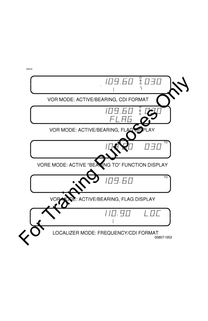
CESSNA
SECTION 9 - SUPPLEMENTS
MODEL 172R
SUPPLEMENT 25 - FAA APPROVED
NAV FUNCTION DISPLAYS
Figure 1. Bendix/King KX 165A VHF NAV/COMM (Sheet 2 of 2)
Jan 31/02
S25-5
SECTION 9 - SUPPLEMENTS
CESSNA
SUPPLEMENT 25 - FAA APPROVED
MODEL 172R
1.
OPERATING COMM FREQUENCY DISPLAY -- Displays
COMM ACTIVE and COMM STANDBY frequencies with a
"T" between them to indicate TRANSMIT and an "R" to
indicate RECEIVE modes of operation.
2.
OPERATING NAV FREQUENCY DISPLAY -- The right
portion of the display is allocated to NAV receiver ACTIVE
and STANDBY information. The frequency channeling is
similar to the COMM when operating in the frequency
mode. The NAV ACTIVE and STANDBY frequencies are
stored in the memory on power down and return on power
up.
3.
NAV STANDBY/OBS/Bearing/Radial/Timer Display -- The
right side of the NAV display is controlled by the MODE
SELECTOR BUTTON (see #7 below). With an active VOR
frequency, this portion of the display shows the STANDBY
frequency, OBS setting for the internal CDI, the bearing to
the VOR station, radial from the VOR station, or a count-
up/count-down timer. With an active localizer frequency,
this portion of the display shows the standby frequency, the
letters "LOC", or count-up/count-down timer.
4.
NAV FREQUENCY SELECTOR KNOB (SMALL)
--
Operates in 50-kHz steps. The NAV receiver's lower and
upper frequency limits are 108.00 MHz and 117.95 MHz.
Exceeding the upper limit of frequency band will
automatically return to the lower limit and vice versa. A
clockwise rotation will increase (inc) the previous frequency
while a counterclockwise rotation will decrease (dec) the
previous frequency.
5.
NAV FREQUENCY SELECTOR KNOB (LARGE)
--
Operates in 1-MHz steps. The frequency inc/dec operates
the STANDBY frequency display. A clockwise rotation will
increase the previous frequency while a counterclockwise
rotation will decrease the previous frequency. Exceeding the
upper limit of the frequency band will automatically return to
the lower limit and vice versa.
S25-6
Jan 31/02
CESSNA
SECTION 9 - SUPPLEMENTS
MODEL 172R
SUPPLEMENT 25 - FAA APPROVED
6.
NAV/FREQUENCY TRANSFER BUTTON
(
)
--
Interchanges the NAV ACTIVE and STANDBY frequencies.
Depressing the NAV frequency transfer button for 2 seconds
or more will cause the display to go into the ACTIVE ENTRY
mode. Only the ACTIVE frequency will be displayed and it can
be directly changed by using the NAV inc/dec knobs. The
display will return to the ACTIVE/STANDBY mode when the
NAV frequency transfer button is pushed.
7.
MODE SELECTOR BUTTON -- Depressing the mode button
will cause the NAV display to go from the ACTIVE/STANDBY
format to the ACTIVE/CDI (Course Deviation Indicator) format.
In the CDI mode, the frequency inc/dec knob (pushed in)
channels the ACTIVE frequency. When the ACTIVE window is
tuned to a VOR frequency, the standby frequency area is
replaced by a three digit OBS (Omni Bearing Selector)
display. The desired OBS course can be selected by pulling
out the inner NAV frequency knob and turning it. This OBS
display is independent of any OBS course selected on an
external CDI. An "OBS" in the middle of the NAV display will
flash while the inner NAV frequency knob is pulled out. The
CDI is displayed on the line below the frequency/OBS. When
the ACTIVE window is tuned to a localizer frequency, the
standby frequency area is replaced by "LOC". When the
received signal is too weak to ensure accuracy the display will
"FLAG".
Depressing the mode button again will cause the NAV display
to go from the ACTIVE/CDI format to the ACTIVE/BEARING
format. In the BEARING mode, the frequency inc/dec knob
channels the ACTIVE frequency window. Depressing the
frequency transfer button will cause the ACTIVE frequency to
be placed in blind storage and the STANDBY frequency (in
blind storage) to be displayed in the ACTIVE window display.
In bearing mode, the right hand window of the NAV display
shows the bearing TO the station. When a too weak or invalid
VOR signal is received the display flags (dashes).
Jan 31/02
S25-7
SECTION 9 - SUPPLEMENTS
CESSNA
SUPPLEMENT 25 - FAA APPROVED
MODEL 172R
Another push of the mode button will cause the NAV display
to go from the ACTIVE/BEARING format to the
ACTIVE/RADIAL format. In the RADIAL mode, the frequency
inc/dec knobs channel the ACTIVE frequency window and
depressing the frequency transfer button will cause the
ACTIVE frequency to be placed in blind storage and the
STANDBY frequency (in blind storage) to be displayed in the
ACTIVE window display. In radial mode of operation, the right
hand window of NAV display shows the radial FROM the
station. When a too weak or invalid VOR signal is received
the display flags (dashes).
Another push of the mode button will cause the unit to go into
the TIMER mode. When the unit is turned on, the elapsed
timer (ET) begins counting upwards from zero. The timer can
be stopped and reset to zero by pushing the NAV frequency
transfer button for 2 seconds or more causing the ET on the
display to flash. In this state, the timer can be set as a
countdown timer or the elapsed timer can be restarted. The
countdown timer is set by using the NAV frequency inc/dec
knobs to set the desired time and then pushing the NAV
frequency transfer button to start the timer. The large knob
selects minutes, the small knob in the "in" position selects 10
second intervals, and the small knob in the "out" position
selects individual seconds. After the countdown timer reaches
zero, the counter will begin to count upwards indefinitely while
flashing for the first 15 seconds. When the elapsed timer is
reset to zero it may be restarted again by momentarily
pushing the NAV frequency transfer button.
8.
NAV/VOLUME CONTROL (PULL IDENT) -- Adjusts volume of
navigation receiver audio. When the knob is pulled out, the
Ident signal plus voice may be heard. The volume of
voice/ident can be adjusted by turning this knob.
9.
COMM FREQUENCY SELECTOR KNOB (INNER) -- This
smaller knob is designed to change the indicated frequency in
steps of 50-kHz when it is pushed in, and in 25-kHz steps
when it is pulled out.
S25-8
Jan 31/02
CESSNA
SECTION 9 - SUPPLEMENTS
MODEL 172R
SUPPLEMENT 25 - FAA APPROVED
10. COMM FREQUENCY SELECTOR KNOB (OUTER) -- The
outer, larger selector knob is used to change the MHz portion
of the frequency display. At either band-edge of the 118-136
MHz frequency spectrum, an offscale rotation will wrap the
display around to the other frequency band-edge (i.e.,
136
MHz advances to 118 MHz).
11. CHANNEL BUTTON -- Pressing the CHAN button for 2 or
more seconds will cause the unit to enter the channel program
(PG) mode. Upon entering the channel program mode, the
channel number will flash indicating that it can be
programmed. The desired channel can be selected by turning
the comm kHz knob. The channel frequency can be entered
by pushing the COMM TRANSFER button which will cause
the standby frequency to flash. The comm frequency knobs
are then used to enter the desired frequency. If dashes
(located between 136 MHz and 118 MHz) are entered instead
of a frequency, the corresponding channel is skipped in
channel selection mode. Additional channels may be
programmed by pressing the COMM TRANSFER button and
using the same procedure. The channel information is saved
by pushing the CHAN button which will also cause the unit to
return to the previous frequency entry mode.
The channel selection mode (CH) can then be entered by
momentarily pushing the CHAN button. The comm frequency
knobs can be used to select the desired channel. The unit will
automatically default to the previous mode if no channel is
selected within 2 seconds after entering the channel selection
mode. The unit is placed in the transmit mode by depressing
a mic button.
Jan 31/02
S25-9
SECTION 9 - SUPPLEMENTS
CESSNA
SUPPLEMENT 25 - FAA APPROVED
MODEL 172R
12. COMM FREQUENCY TRANSFER BUTTON (
)
--
Interchanges the frequencies in the USE and STANDBY
displays. To tune the radio to the desired operating frequency,
the desired frequency must be entered into the standby
display and then the COMM TRANSFER button must be
pushed. This will trade the contents of the active and standby
displays. The operating frequency can also be entered by
accessing the ACTIVE ENTRY (direct tune) mode which is
done by pushing the COMM TRANSFER button for 2 or more
seconds. In the direct tune mode, only the active part of the
display is visible. The desired frequency can be directly
entered into the display. Push the COMM TRANSFER button
again to return to the active/standby display.
The transceiver is always tuned to the frequency appearing in
the ACTIVE display. It is, therefore, possible to have two
different frequencies stored in the ACTIVE and STANDBY
displays and to change back and forth between them at the
simple push of the COMM TRANSFER button.
13. COMM VOLUME CONTROL (OFF/PULL/TEST) -- Rotate the
VOL knob clockwise from the OFF position. Pull the VOL knob
out and adjust for desired listening level. Push the VOL knob
back in to actuate the automatic squelch. The VOL knob may
also be pulled out to hear particularly weak signals.
SECTION 2
LIMITATIONS
There is no change to the airplane limitations when this avionic
equipment is installed.
S25-10
Jan 31/02
CESSNA
SECTION 9 - SUPPLEMENTS
MODEL 172R
SUPPLEMENT 25 - FAA APPROVED
SECTION 3
EMERGENCY PROCEDURES
There is no change to the airplane emergency procedures when
this avionic equipment is installed. However, if the frequency
readouts fail, the radio will remain operational on the last frequency
selected. If either frequency transfer button is pressed and held
while power is applied to the unit, the unit wakes up with 120.00
MHz in the COMM use frequency and 110.00 MHz in the NAV
active frequency, with both COMM and NAV in the active entry
mode. This will aid the pilot in blind tuning the radio.
SECTION 4
NORMAL PROCEDURES
COMMUNICATION RECEIVER-TRANSMITTER OPERATION:
1. OFF/PULL/TEST Volume Control -- Turn clockwise; pull out
and adjust to desired audio level; push control back in to
activate the automatic squelch.
2. MIC Selector Switch (on audio control panel) -- SET to COMM
1.
3. SPEAKER Selector (on audio control panel) -- SET to desired
mode.
4. COMM Frequency Selector Knobs -- Select desired operating
frequency.
5. COMM TRANSFER Button -- PRESS to transfer desired
frequency from the STBY display into the COMM display.
6. Mic Button:
a. To transmit -- Press button and speak in microphone.
NOTE
During COMM transmission, a lighted "T" will appear
between the "COMM" and "STBY" displays to indicate that
the transceiver is operating in the transmit mode.
b. To Receive -- RELEASE mike button.
Jan 31/02
S25-11
SECTION 9 - SUPPLEMENTS
CESSNA
SUPPLEMENT 25 - FAA APPROVED
MODEL 172R
NAVIGATION RECEIVER OPERATION:
1. NAV Frequency Selector Knobs -- SELECT desired operating
frequency in "STBY" display.
2. NAV TRANSFER BUTTON -- PRESS to transfer desired
frequency from the "STBY" display into the "NAV" display.
3. Speaker Selector (on audio control panel) -- SET to desired
mode.
4. NAV Volume Control --
a. ADJUST to desired audio level.
b. PULL out to identify station.
VOR OPERATION:
Channel the NAV Receiver to the desired VOR and monitor the
audio to positively identify the station. To select an OBS course,
turn the OBS knob to set the desired course under the lubber line.
When a signal is received, the NAV flag will pull out of view and
show a "TO" or "FROM" flag as appropriate for the selected
course.
LOC OPERATION:
Localizer circuitry is energized when the NAV Receiver is
channeled to an ILS frequency. Monitor the LOC audio and
positively identify the station. The NAV flag will be out of view when
the signal is of sufficient strength to be usable.
GLIDESLOPE OPERATION:
The glideslope receiver is automatically channeled when a
localizer frequency is selected. A separate warning flag is provided
to indicate usable signal conditions.
PILOT CONFIGURATION:
This mode can be accessed by pressing and holding the NAV
Mode Button for more than 2 seconds and then pressing the Nav
Frequency Transfer Button for an additional
2 seconds, while
continuing to hold the NAV Mode Button. When the Pilot Config
Mode is entered, the unit will show the "SWRV" mnemonic which is
the unit software revision level. Adjustment pages can be accessed
by MODE button presses.
S25-12
Jan 31/02
CESSNA
SECTION 9 - SUPPLEMENTS
MODEL 172R
SUPPLEMENT 25 - FAA APPROVED
The pilot may adjust two parameters in the pilot configuration, the
display minimum brightness and sidetone volume level. Minimum
Brightness (BRIM) will have a range of 0-255. The dimmest is 0
and the brightest is 255. Sidetone volume level is adjusted when
SIDE is displayed. Values from 0-255 may be selected with 0 being
least volume, 255 being the greatest.
Adjustment
Mnemonic
Min Level
Max Level
Software Revision Number
SWRV
- - -
- - -
Minimum Display Brightness
BRIM
0
255
Sidetone Level
SIDE
0
255
Subsequent presses of the MODE button sequences through
SWRV, BRIM, SIDE, and then back to SWRV.
Pressing the NAV Transfer Button momentarily exits Pilot
configuration mode. The NAV returns to its pre-Pilot Config state
with the new brightness and sidetone levels stored in nonvolatile
memory.
SECTION 5
PERFORMANCE
There is no change to the airplane performance when this
avionic equipment is installed. However, the installation of an
externally mounted antenna, or several related antennas, will result
in a minor reduction in cruise performance.
Jan 31/02
S25-13 (S25-14 blank)
Pilot's Operating Handbook and
FAA Approved Airplane Flight Manual
CESSNA MODEL 172R
AIRPLANES 17281201 AND ON
SUPPLEMENT 26
BENDIX/KING KDR 510
FLIGHT INFORMATION SERVICES (FIS)
SERIAL NO.
REGISTRATION NO.
This supplement must be inserted into Section 9 of the Pilot's Operating Handbook
and FAA Approved Airplane Flight Manual when the airplane is equipped with the
Bendix/King KDR 510 Flight Information Services (FIS).
Member of GAMA
7 JANUARY 2004
COPYRIGHT ” 2004
CESSNA AIRCRAFT COMPANY
WICHITA, KANSAS, USA
172RPHUS-S26-00
S26-1
SECTION 9 - SUPPLEMENTS
CESSNA
SUPPLEMENT 26 - FAA APPROVED
MODEL 172R
SUPPLEMENT 26
BENDIX/KING KDR 510
FLIGHT INFORMATION SERVICES (FIS)
Use the Log of Effective Pages to determine the current status of
this supplement. Pages affected by the current revision are
indicated by an asterisk (*) preceding the page number.
Supplement Status
Date
Original
7 January 2004
LOG OF EFFECTIVE PAGES
Page
Page
Revision
Number
Status
Number
S26-1 thru S26-3/S26-4
Original
0
S26-5 thru S26-6
Original
0
S26-2
Original
CESSNA
SECTION 9 - SUPPLEMENTS
MODEL 172R
SUPPLEMENT 26 - FAA APPROVED
SUPPLEMENT 26
BENDIX/KING KDR 510
FLIGHT INFORMATION SERVICES (FIS)
SERVICE BULLETIN CONFIGURATION LIST
The following is a list of Service Bulletins that are applicable to the
operation of the airplane, and have been incorporated into this
supplement. This list contains only those Service Bulletins that are
currently active.
Airplane
Serial
Revision
Incorporated
Number
Title
Effectivity
Incorporation
In Airplane
Original
S26-3/S26-4
CESSNA
SECTION 9 - SUPPLEMENTS
MODEL 172R
SUPPLEMENT 26 - FAA APPROVED
SUPPLEMENT
BENDIX/KING KDR 510
FLIGHT INFORMATION SERVICES (FIS)
SECTION 1
GENERAL
The Bendix/King KDR
510 Flight Information Services (FIS)
installation provides weather information and other flight advisory
information to pilots to enhance situational awareness. The services
rely on a network of ground based VHF transmitters that
continuously broadcast data to any aircraft within line-of-sight of the
transmitter. The aircraft must be equipped with a dedicated VHF
antenna and receiver for FIS. Data is then presented to the pilot
using the KMD 550 multi-function display.
FIS information is
intended to be used as a strategic planning tool to help the pilot
avoid inclement weather areas that are beyond his visual range.
FIS lacks the sufficient resolution and update rate necessary for
severe weather penetration.
NOTE
Cessna Aircraft Company does not guarantee the
quality, accuracy, or availability of FIS data. Some data
is available to all KDR 510 installations while other data
is available only by subscription.
The network of
transmitters may not cover the entire area where the
aircraft is operated, and the aircraft may need to be
above 5000 feet AGL to receive FIS data in areas where
coverage does exist.
SECTION 2
LIMITATIONS
Use of the Bendix/King KDR 510 Flight Information Services (FIS)
for severe weather penetration is prohibited.
Original
S26-5
SECTION 9 - SUPPLEMENTS
CESSNA
SUPPLEMENT 26 - FAA APPROVED
MODEL 172R
SECTION 3
EMERGENCY PROCEDURES
No additional emergency procedures are required when the KDR
510 Flight Information Services (FIS) equipment is installed in the
airplane.
SECTION 4
NORMAL PROCEDURES
Press the WX function select key of the KMD 550 multi-function
display to toggle through weather related systems installed on the
aircraft that display on the KMD 550. The MODE button toggles
between different weather related information displays such as
switching between METARs and PIREPs. It is highly recommended
that the pilot read the Bendix/King subscription agreement and the
FIS addendum to the KMD 550/850 Pilot's Guide to understand the
entire range of information available. It is possible that data
availability and subscription services may change over time.
SECTION 5
PERFORMANCE
Airplane performance does not change when the KDR 510 Flight
Information Services (FIS) equipment is installed.
S26-6
Original