CESSNA 172R NAV I/NAV II Skyhawk MODEL 172R. Information Manual (2016) - page 1
172R NAV I/NAV II Skyhawk
Information Manual
MODEL 172R
NAV I/NAV II AVIONICS OPTION
Serials 17280001 thru 17281356
CESSNA
INTRODUCTION
MODEL 172R
NAV I/NAV II
NOTICE
AT THE TIME OF ISSUANCE, THIS INFORMATION
MANUAL WAS AN EXACT DUPLICATE OF THE
OFFICIAL PILOT’S OPERATING HANDBOOK AND
FAA APPROVED AIRPLANE FLIGHT MANUAL AND
IS TO BE USED FOR GENERAL PURPOSES ONLY.
IT WILL NOT BE KEPT CURRENT AND,
THEREFORE, CANNOT BE USED AS A
SUBSTITUTE FOR THE OFFICIAL PILOT’S
OPERATING HANDBOOK AND FAA APPROVED
AIRPLANE FLIGHT MANUAL INTENDED FOR
OPERATION OF THE AIRPLANE.
THE PILOT’S OPERATING HANDBOOK MUST BE
CARRIED IN THE AIRPLANE AND AVAILABLE TO
THE PILOT AT ALL TIMES.
Cessna Aircraft Company
Original Issue - 2 December 1996
Revision 9 - 19 July 2004
Revision 9
U.S.
i
INTRODUCTION
CESSNA
MODEL 172R
NAV I/NAV II
PERFORMANCE - SPECIFICATIONS
*SPEED:
Maximum at Sea Level
123 KNOTS
Cruise, 80% Power at 8000 Feet
122 KNOTS
CRUISE: Recommended lean mixture with fuel allowance for engine
start, taxi, takeoff, climb and 45 minutes reserve.
80% Power at 8000 Feet
Range - 580 NM
53 Gallons Usable Fuel
Time - 4.8 HOURS
Range at 10,000 Feet, 60% Power
Range - 687 NM
53 Gallons Usable Fuel
Time - 6.6 HOURS
RATE-OF-CLIMB AT SEA LEVEL
720 FPM
SERVICE CEILING
13,500 FEET
TAKEOFF PERFORMANCE:
Ground Roll
945 FEET
Total Distance Over 50 Foot Obstacle
1685 FEET
LANDING PERFORMANCE:
Ground Roll
550 FEET
Total Distance Over 50 Foot Obstacle
1295 FEET
STALL SPEED:
Flaps UP, Power Off
51 KCAS
Flaps FULL, Power Off
47 KCAS
MAXIMUM WEIGHT:
Ramp
2457 POUNDS
Takeoff
2450 POUNDS
Landing
2450 POUNDS
(Continued Next Page)
ii
U.S.
Revision 9
CESSNA
INTRODUCTION
MODEL 172R
NAV I/NAV II
PERFORMANCE - SPECIFICATIONS (Continued)
STANDARD EMPTY WEIGHT
1639 POUNDS
MAXIMUM USEFUL LOAD
818 POUNDS
BAGGAGE ALLOWANCE
120 POUNDS
WING LOADING
14.1 lbs/sq. ft.
POWER LOADING
15.3 lbs/HP
FUEL CAPACITY
56 GALLONS
OIL CAPACITY
8 QUARTS
ENGINE: Textron Lycoming
IO-360-L2A
160 BHP at 2400 RPM
PROPELLER:
Fixed Pitch, Diameter
75 INCHES
NOTE
*Speed performance is shown for an airplane equipped with
speed fairings which increase the speeds by
approximately 2 knots. There is a corresponding difference
in range, while all other performance figures are
unchanged when speed fairings are installed.
The above performance figures are based on airplane weights at 2450
pounds, standard atmospheric conditions, level, hard-surfaced dry
runways and no wind. They are calculated values derived from flight
tests conducted by Cessna Aircraft Company under carefully
documented conditions and will vary with individual airplanes and
numerous factors affecting flight performance.
Revision 9
U.S.
iii/iv
CESSNA
INTRODUCTION
MODEL 172R
NAV I/NAV II
Cessna Aircraft Company
Model 172R
NAV I/NAV II AVIONICS OPTION
Serials 17280001 thru 17281356
THIS MANUAL INCORPORATES INFORMATION ISSUED IN THE
PILOT'S OPERATING HANDBOOK AND FAA APPROVED
AIRPLANE FLIGHT MANUAL AT REVISION 9, DATED 19 JULY 2004
(PART NUMBER 172RPHUS-09).
COPYRIGHT © 1996
CESSNA AIRCRAFT COMPANY
WICHITA, KANSAS USA
172RIMUS-09
Revision 9
U.S.
v/vi
CESSNA
INTRODUCTION
MODEL 172R
NAV I/NAV II
TABLE OF CONTENTS
SECTION
GENERAL
1
LIMITATIONS
2
EMERGENCY PROCEDURES
3
NORMAL PROCEDURES
4
PERFORMANCE
5
WEIGHT AND BALANCE/EQUIPMENT LIST
6
AIRPLANE AND SYSTEMS DESCRIPTION
7
HANDLING, SERVICE AND MAINTENANCE
8
SUPPLEMENTS
9
Revision 9
U.S.
vii/viii
CESSNA
SECTION 9
MODEL 172R NAV I/NAV II
SUPPLEMENTS
KAP 140 AUTOPILOT
LOG OF APPROVED SUPPLEMENTS
NOTE
It is the airplane owner's responsibility to make sure that he
or she has the latest revision to each supplement of a
Pilot's Operating Handbook, and the latest issued “Log Of
Approved Supplements”. this “Log Of Approved
Supplements” was the latest version as of the date it was
shipped by Cessna; however, some changes may have
occurred, and the owner should verify this is the latest,
most up-to-date version by contacting Cessna Propeller
Aircraft Customer Services at (316) 517-5800.
Supplement
Name
Revision Equipment
Number
Level
Installed
1
Bendix/King KX 155A VHF NAV/
1
COMM with KI 208 or KI 209A
Indicator Head
2
Bendix/King KT 76C Transponder
with Blind Encoder
1
3
Bendix/King KMA
26 Audio
Selector Panel
1
4
Pointer Model 3000-11 or Model
4000-11 Emergency Locator
Transmitter (ELT)
3
5
Bendix/King KLN
89B Global
Positioning System (IFR)
2
6
Bendix/King KR
87 Automatic
Direction Finder (ADF)
1
7
Bendix/King KAP 140 Single Axis
Autopilot
4
8
Winterization Kit
1
9
Davtron Model 803 Clock/OAT
2
10
Bendix/King KLN 89 VFR Global
Positioning System (GPS)
1
11
Brazilian Certified Airplanes
0
(Continued Next Page)
172RPHUSLOG-13
15 May 2013
U.S.
Log 1
SECTION 9
CESSNA
SUPPLEMENTS
MODEL 172R NAV I/NAV II
KAP 140 AUTOPILOT
LOG OF APPROVED SUPPLEMENTS
Supplement
Name
Revision Equipment
Number
Level
Installed
12
Canadian Supplement
1
13
Bendix/King KCS-55A Slaved
Compass System with KI-525A
Horizontal Situation Indicator
(HSI)
1
14
Argentine Supplement
0
15
Bendix/King KAP
140
2 Axis
Autopilot
3
16
Bendix/King KT
73 Mode S
Transponder
0
17
Reserved
18
Ukrainian Certified Airplanes
0
19
Bendix/King KLN
94 Global
Positioning System (IFR)
4
20
Bendix/King KMA
28 Audio
Selector Panel
0
21
Bendix/King KMD
550 Multi-
Function Display
0
22
12 Volt Cabin Power System
0
23
Reserved
24
Astrotech Model TC-2 Clock/OAT/
Volt Indicator
0
25
Bendix/King KX 165A VHF NAV/
COMM
0
26
Bendix/King KDR
510 Flight
Information Services (FIS)
0
172RPHUSLOG-13
Log 2
U.S.
15 May 2013
Pilot's Operating Handbook and
FAA Approved Airplane Flight Manual
CESSNA MODEL 172R
AIRPLANES 172R80001 AND ON
SUPPLEMENT 1
BENDIX/KING KX 155A
VHF NAV/COMM
with KI 208 or KI 209A INDICATOR HEAD
SERIAL NO.
REGISTRATION NO.
This supplement must be inserted into Section
9 of the Pilot's Operating
Handbook and FAA Approved Airplane Flight Manual.
FAA APPROVAL
Date: 3 April 2000
Member of GAMA
2 December 1996
COPYRIGHT ” 1996
CESSNA AIRCRAFT COMPANY
WICHITA, KANSAS, USA
Revision 1 - 28 February 2000
172RPHUS-S1-01
S1-1
SECTION 9 - SUPPLEMENTS
CESSNA
SUPPLEMENT 1 - FAA APPROVED
MODEL 172R
SUPPLEMENT 1
BENDIX/KING KX 155A VHF NAV/COMM with KI
208 or KI 209A INDICATOR HEAD
The following Log of Effective Pages provides the date of issue
for original and revised pages, as well as a listing of all pages in
the Supplement. Pages which are affected by the current
revision will carry the date of that revision
Revision Level
Date of Issue
0 (Original)
Dec. 2, 1996
1
Feb. 28, 2000
LOG OF EFFECTIVITY PAGES
_______________________________
PAGE
DATE
PAGE
DATE
Title (S1-1)
Feb 28/00
S1-9
Dec 2/96
S1-2
Feb 28/00
S1-10
Dec 2/96
S1-3
Feb 28/00
S1-11
Dec 2/96
S1-4
Dec 2/96
S1-12
Dec 2/96
S1-5
Dec 2/96
S1-13
Feb 28/00
S1-6
Dec 2/96
S1-14
Dec 2/96
S1-7
Dec 2/96
S1-15
Dec 2/96
S1-8
Feb 28/00
S1-16 Blank
Dec 2/96
SERVICE BULLETIN CONFIGURATION LIST
The following is a list of Service Bulletins that are applicable to
the operation of the airplane, and have been incorporated into
this supplement. This list contains only those Service Bulletins
that are currently active.
Airplane
Unit
Revision
Incorporated
Number Title
Effectivity
Incorporation
In Airplane
S1-2
Feb 28/00
CESSNA
SECTION 9 - SUPPLEMENTS
MODEL 172R
SUPPLEMENT 1 - FAA APPROVED
SUPPLEMENT
BENDIX/KING KX 155A VHF NAV/COMM with
KI 208 or KI 209A INDICATOR HEAD
SECTION 1
GENERAL
The Bendix/King KX 155A VHF Nav/Comm, shown in Figure 1,
consists of a panel-mounted receiver-transmitter and a KI 208 or KI
209A Indicator.
The set includes a 760-channel VHF communications receiver-
transmitter and a 200-channel VHF navigation receiver. A 40-
channel glide- slope receiver is also included if the KI
209A
indicator is used. The communications receiver-transmitter receives
and transmits signals between 118.00 and 136.975 MHz with 25-
kHz spacing. Optional 8.33 kHz (2280 channel) Comm is available.
The navigation receiver receives VOR and localizer signals between
108.00 and 117.95 MHz in 50-kHz steps. The glide slope receiver
is automatically tuned when a localizer frequency is selected. The
circuits required to interpret the VOR and localizer signals are also
an integral part of the Nav receiver.
Large self-dimming gas discharge readouts display both the
communications and navigation operating frequencies. The KX-
155A's "flip-flop" preselect feature enables you to store one
frequency in the standby display while operating on another and
then interchange them instantly with the touch of a button. Both the
active (COMM) and the standby (STBY) frequencies may be
displayed at all times and are stored in nonvolatile memory without
drain on the aircraft battery. KX 155A has 32 programmable comm
channels, a stuck microphone alert and transmitter shutdown,
Bearing To/From radial mode, course deviation indicator mode and
an elapsed timer mode.
Feb 28/00
S1-3
SECTION 9 - SUPPLEMENTS
CESSNA
SUPPLEMENT 1 - FAA APPROVED
MODEL 172R
The Comm portion incorporates an automatic squelch. To
override the automatic squelch, the Comm volume control knob is
pulled out. Push the knob back in to reactivate the automatic
squelch. A "T" will be displayed during transmit and "R" during
valid signal reception.
The Nav portion uses the pull out feature of the Nav volume
control to receive the Nav signal Ident. Pull the volume control
knob out to hear the Ident signal plus voice. Push the knob in to
attenuate the Ident signal and still hear Nav voice.
All controls for the Nav/Comm, except those for navigation
course selection, are mounted on the front panel of the receiver-
transmitter. Control lighting is provided by NAV/COMM interior
lighting and the instrument panel flood lighting system. Operation
and description of the audio selector panel used in conjunction with
this radio is shown and described in Supplement 3 in this section.
NOTE
The unit has a stuck microphone alert feature. If the
microphone is keyed continuously for greater than
33 seconds, the transmitter stops transmitting and
the active Comm frequency flashes to alert the pilot
of the stuck mic condition.
S1-4
Dec 2/96

CESSNA
SECTION 9 - SUPPLEMENTS
MODEL 172R
SUPPLEMENT 1 - FAA APPROVED
1
2
3
4
5
13
12
11
10
9
8
7
6
KX 155A VHF NAV/COMM
19
14
18
15
14
16
17
KI 209A INDICATOR
16
0585C1045
18
KI 208 INDICATOR HEAD
0585C1046
0585C1047
Figure 1. Bendix/King KX 155A VHF NAV/COMM with KI 208 or
KI 209A Indicator Head (Sheet 1 of 7)
Dec 2/96
S1-5

SECTION 9 - SUPPLEMENTS
CESSNA
SUPPLEMENT 1 - FAA APPROVED
MODEL 172R
NAV FUNCTION DISPLAYS
VOR MODE: ACTIVE/BEARING, CDI FORMAT
VOR MODE: ACTIVE/BEARING, FLAG DISPLAY
VOR MODE: ACTIVE ”BEARING TO” FUNCTION DISPLAY
VOR MODE: ACTIVE/BEARING, FLAG DISPLAY
LOCALIZER MODE: FREQUENCY/CDI FORMAT
Figure 1. Bendix/King KX 155A VHF NAV/COMM with KI 208 or
KI 209A Indicator Head (Sheet 2 of 7)
S1-6
Dec 2/96
CESSNA
SECTION 9 - SUPPLEMENTS
MODEL 172R
SUPPLEMENT 1 - FAA APPROVED
1.
OPERATING COMM FREQUENCY DISPLAY
-- Displays
COMM ACTIVE and COMM STANDBY frequencies with a "T"
between them to indicate TRANSMIT and an "R" to indicate
RECEIVE modes of operation.
2.
OPERATING NAV FREQUENCY DISPLAY -- The right
portion of the display is allocated to NAV receiver ACTIVE and
STANDBY information. The frequency channeling is similar to
the COMM when operating in the frequency mode. The NAV
ACTIVE and STANDBY frequencies are stored in the memory
on power down and return on power up.
3.
NAV STANDBY/OBS/Bearing/Radial/Timer Display -- The right
side of the NAV display is controlled by the MODE
SELECTOR BUTTON (see #7 below). With an active VOR
frequency, this portion of the display shows the STANDBY
frequency, OBS setting for the internal CDI, the bearing to the
VOR station, radial from the VOR station, or a count-up/count-
down timer. With an active localizer frequency, this portion of
the display shows the standby frequency, the letters "LOC", or
count-up/count-down timer.
4.
NAV FREQUENCY SELECTOR KNOB (SMALL) -- Operates
in
50 kHz steps. The NAV receiver's lower and upper
frequency limits are 108.00 MHz and 117.95 MHz. Exceeding
the upper limit of frequency band will automatically return to
the lower limit and vice versa. A clockwise rotation will
increase (inc) the previous frequency while a counterclockwise
rotation will decrease (dec) the previous frequency.
5.
NAV FREQUENCY SELECTOR KNOB (LARGE) -- Operates
in
1 MHz steps. The frequency inc/dec operates the
STANDBY frequency display. A clockwise rotation will
increase the previous frequency while a counterclockwise
rotation will decrease the previous frequency. Exceeding the
upper limit of the frequency band will automatically return to
the lower limit and vice versa.
Figure 1. Bendix/King KX 155A VHF NAV/COMM with KI 208 or KI
209A Indicator Head (Sheet 3 of 7)
Dec 2/96
S1-7
SECTION 9 - SUPPLEMENTS
CESSNA
SUPPLEMENT 1 - FAA APPROVED
MODEL 172R
6.
NAV/FREQUENCY TRANSFER BUTTON
(
)
--
Interchanges the NAV Active and STANDBY frequencies.
Depressing the NAV frequency transfer button for 2 seconds
or more will cause the display to go into the ACTIVE ENTRY
mode. Only the ACTIVE frequency will be displayed and it can
be directly changed by using the NAV inc/dec knobs. The
display will return to the ACTIVE/STANDBY mode when the
NAV frequency transfer button is pushed.
7.
MODE SELECTOR BUTTON -- Depressing the mode button
will cause the NAV display to go from the ACTIVE/STANDBY
format to the ACTIVE/CDI (Course Deviation Indicator) format.
In the CDI mode, the frequency inc/dec knob (pushed in)
channels the ACTIVE frequency. When the ACTIVE window is
tuned to a VOR frequency, the standby frequency area is
replaced by a three digit OBS (Omni Bearing Selector)
display. The desired OBS course can be selected by pulling
out the inner NAV frequency knob and turning it. This OBS
display is independent of any OBS course selected on an
external CDI. An "OBS" in the middle of the NAV display will
flash while the inner NAV frequency knob is pulled out. The
CDI is displayed on the line below the frequency/OBS. When
the ACTIVE window is tuned to a localizer frequency, the
standby frequency area is replaced by "LOC". When the
received signal is too weak to ensure accuracy the display will
"FLAG".
Depressing the mode button again will cause the NAV display
to go from the ACTIVE/CDI format to the ACTIVE/BEARING
format. In the BEARING mode, the frequency inc/dec knob
channels the ACTIVE frequency window. Depressing the
frequency transfer button will cause the ACTIVE frequency to
be placed in blind storage and the STANDBY frequency (in
blind storage) to be displayed in the ACTIVE window display.
In bearing mode, the right hand window of the NAV display
shows the bearing TO the station. When a too weak or invalid
VOR signal is received the display flags (dashes).
Figure 1. Bendix/King KX 155A VHF NAV/COMM with KI 208 or KI
209A Indicator Head (Sheet 4 of 7)
S1-8
Feb 28/00
CESSNA
SECTION 9 - SUPPLEMENTS
MODEL 172R
SUPPLEMENT 1 - FAA APPROVED
Another push of the mode button will cause the NAV display
to go from the ACTIVE/BEARING format to the
ACTIVE/RADIAL format. In the RADIAL mode, the frequency
inc/dec knobs channel the ACTIVE frequency window and
depressing the frequency transfer button will cause the
ACTIVE frequency to be placed in blind storage and the
STANDBY frequency (in blind storage) to be displayed in the
ACTIVE window display. In radial mode of operation, the right
hand window of NAV display shows the radial FROM the
station. When a too weak or invalid VOR signal is received
the display flags (dashes).
Another push of the mode button will cause the unit to go into
the TIMER mode. When the unit is turned on, the elapsed
timer (ET) begins counting upwards from zero. The timer can
be stopped and reset to zero by pushing the NAV frequency
transfer button for 2 seconds or more causing the ET on the
display to flash. In this state, the timer can be set as a
countdown timer or the elapsed timer can be restarted. The
countdown timer is set by using the NAV frequency inc/dec
knobs to set the desired time and then pushing the NAV
frequency transfer button to start the timer. The large knob
selects minutes, the small knob in the "in" position selects 10
second intervals, and the small knob in the "out" position
selects individual seconds. After the countdown timer reaches
zero, the counter will begin to count upwards indefinitely while
flashing for the first 15 seconds. When the elapsed timer is
reset to zero it may be restarted again by momentarily
pushing the NAV frequency transfer button.
8. NAV/VOLUME CONTROL (PULL IDENT) -- Adjusts volume of
navigation receiver audio. When the knob is pulled out, the
Ident signal plus voice may be heard. The volume of
voice/ident can be adjusted by turning this knob.
Figure 1. Bendix/King KX 155A VHF NAV/COMM with KI 208 or KI
209A Indicator Head (Sheet 5 of 7)
Dec 2/96
S1-9
SECTION 9 - SUPPLEMENTS
CESSNA
SUPPLEMENT 1 - FAA APPROVED
MODEL 172R
9.
COMM FREQUENCY SELECTOR KNOB (INNER) -- This
smaller knob is designed to change the indicated frequency in
steps of 50-kHz when it is pushed in, and in 25-kHz steps
when it is pulled out. For 8.33 kHz versions, channels are
incremented in 25 kHz steps with the knob pushed in and
8.33 kHz with the knob pulled out.
10. COMM FREQUENCY SELECTOR KNOB (OUTER) -- The
outer, larger selector knob is used to change the MHz portion
of the frequency display. At either band-edge of the 118-136
MHz frequency spectrum, an offscale rotation will wrap the
display around to the other frequency band-edge (i.e.,
136
MHz advances to 118 MHz).
11. CHANNEL BUTTON -- Pressing the CHAN button for 2 or
more seconds will cause the unit to enter the channel program
(PG) mode. Upon entering the channel program mode, the
channel number will flash indicating that it can be
programmed. The desired channel can be selected by turning
the comm kHz knob. The channel frequency can be entered
by pushing the comm transfer button which will cause the
standby frequency to flash. The comm frequency knobs are
then used to enter the desired frequency. If dashes (located
between 136 MHz and 118 MHz) are entered instead of a
frequency, the corresponding channel is skipped in channel
selection mode. Additional channels may be programmed by
pressing the COMM transfer button and using the same
procedure. The channel information is saved by pushing the
CHAN button which will also cause the unit to return to the
previous frequency entry mode.
The channel selection mode (CH) can then be entered by
momentarily pushing the CHAN button. The comm frequency
knobs can be used to select the desired channel. The unit will
automatically default to the previous mode if no channel is
selected within 2 seconds after entering the channel selection
mode. The unit is placed in the transmit mode by depressing
a mic button.
Figure 1. Bendix/King KX 155A VHF NAV/COMM with KI 208 or KI
209A Indicator Head (Sheet 6 of 7)
S1-10
Dec 2/96
CESSNA
SECTION 9 - SUPPLEMENTS
MODEL 172R
SUPPLEMENT 1 - FAA APPROVED
12. COMM FREQUENCY TRANSFER BUTTON (
) --
Interchanges the frequencies in the USE and STANDBY
displays. To tune the radio to the desired operating frequency,
the desired frequency must be entered into the standby
display and then the transfer button must be pushed. This will
trade the contents of the active and standby displays. The
operating frequency can also be entered by accessing the
ACTIVE ENTRY (direct tune) mode which is done by pushing
the COMM TRANSFER button for 2 or more seconds. In the
direct tune mode, only the active part of the display is visible.
The desired frequency can be directly entered into the display.
Push the COMM TRANSFER button again to return to the
active/standby display.
The transceiver is always tuned to the frequency appearing in
the ACTIVE display. It is, therefore, possible to have two
different frequencies stored in the ACTIVE and STANDBY
displays and to change back and forth between them at the
simple push of the transfer button.
13. COMM VOLUME CONTROL (OFF/PULL/TEST) -- Rotate the
VOL knob clockwise from the OFF position. Pull the VOL knob
out and adjust for desired listening level. Push the VOL knob
back in to actuate the automatic squelch. The VOL knob may
also be pulled out to hear particularly weak signals.
14. VOR/Localizer Needle or CDI needle.
15. Glideslope Flag
16. TO-FROM-NAV FLAG
17. Azimuth Card
18. OBS Knob
19. Glideslope Needle
Figure 1. Bendix/King KX 155A VHF NAV/COMM with KI 208 or KI
209A Indicator Head (Sheet 7 of 7)
Dec 2/96
S1-11
SECTION 9 - SUPPLEMENTS
CESSNA
SUPPLEMENT 1 - FAA APPROVED
MODEL 172R
SECTION 2
LIMITATIONS
There is no change to the airplane limitations when this avionic
equipment is installed.
SECTION 3
EMERGENCY PROCEDURES
There is no change to the airplane emergency procedures when
this avionic equipment is installed. However, if the frequency
readouts fail, the radio will remain operational on the last frequency
selected. If either frequency transfer button is pressed and held
while power is applied to the unit, the unit wakes up with 120.00
MHz in the COMM use frequency and 110.00 MHz in the NAV
active frequency, with both COMM and NAV in the active entry
mode. This will aid the pilot in blind tuning the radio.
SECTION 4
NORMAL PROCEDURES
COMMUNICATION RECEIVER-TRANSMITTER OPERATION:
1. OFF/PULL/TEST Volume Control -- Turn clockwise; pull out
and adjust to desired audio level; push control back in to
activate the automatic squelch.
2. MIC Selector Switch (on audio control panel) -- SET to COMM
1.
3. SPEAKER Selector (on audio control panel) -- SET to desired
mode.
4. COMM Frequency Selector Knobs -- Select desired operating
frequency.
5. COMM Transfer Button
-- PRESS to transfer desired
frequency from the STBY display into the COMM display.
S1-12
Dec 2/96
CESSNA
SECTION 9 - SUPPLEMENTS
MODEL 172R
SUPPLEMENT 1 - FAA APPROVED
6. Mic Button:
a. To transmit -- Press button and speak in microphone.
NOTE
During COMM transmission, a lighted "T" will appear
between the "COMM" and "STBY" displays to indicate that
the transceiver is operating in the transmit mode.
b. To Receive -- RELEASE mike button.
NAVIGATION RECEIVER OPERATION:
1. NAV Frequency Selector Knobs -- SELECT desired operating
frequency in "STBY" display.
2. NAV TRANSFER BUTTON -- PRESS to transfer desired
frequency from the "STBY" display into the "NAV" display.
3. Speaker Selector (on audio control panel) -- SET to desired
mode..
4. NAV Volume Control --
a. ADJUST to desired audio level.
b. PULL out to identify station.
VOR OPERATION:
Channel the NAV Receiver to the desired VOR and monitor the
audio to positively identify the station. To select an OBS course,
turn the OBS knob to set the desired course under the lubber line.
When a signal is received, the NAV flag will pull out of view and
show a "TO" or "FROM" flag as appropriate for the selected
course.
LOC OPERATION
Localizer circuitry is energized when the NAV Receiver is
channeled to an ILS frequency. Monitor the LOC audio and
positively identify the station. The NAV flag will be out of view when
the signal is of sufficient strength to be usable.
Feb 28/00
S1-13
SECTION 9 - SUPPLEMENTS
CESSNA
SUPPLEMENT 1 - FAA APPROVED
MODEL 172R
GLIDESLOPE OPERATION
The glideslope receiver is automatically channeled when a
localizer frequency is selected. A separate warning flag is provided
to indicate usable signal conditions.
PILOT CONFIGURATION
This mode can be accessed by pressing and holding the NAV
Mode Button for more than 2 seconds and then pressing the Nav
Frequency Transfer Button for an additional
2 seconds, while
continuing to hold the NAV Mode Button. When the Pilot Config
Mode is entered the unit will show the "SWRV" mnemonic which is
the unit software revision level. Adjustment pages can be accessed
by MODE button presses.
The pilot may adjust two parameters in the pilot configuration, the
display minimum brightness and sidetone volume level. Minimum
Brightness (BRIM) will have a range of 0-255. The dimmest is 0
and the brightest is 255. Sidetone volume level is adjusted when
SIDE is displayed. Values from 0-255 may be selected with 0 being
least volume, 255 being the greatest.
Adjustment
Mnemonic
Min Level
Max Level
Software Revision Number
SWRV
- - -
- - -
Minimum Display Brightness
BRIM
0
255
Sidetone Level
SIDE
0
255
S1-14
Dec 2/96
CESSNA
SECTION 9 - SUPPLEMENTS
MODEL 172R
SUPPLEMENT 1 - FAA APPROVED
Subsequent presses of the MODE button sequences through
SWRV, BRIM, SIDE, and then back to SWRV.
Pressing the NAV Transfer Button momentarily exits Pilot
configuration mode. The NAV returns to its pre-Pilot Config state
with the new brightness and sidetone levels stored in nonvolatile
memory.
SECTION 5
PERFORMANCE
There is no change to the airplane performance when this
avionic equipment is installed. However, the installation of an
externally mounted antenna, or several related antennas, will result
in a minor reduction in cruise performance.
Dec 2/96
S1-15/(S1-16 Blank)
Pilot's Operating Handbook and
FAA Approved Airplane Flight Manual
CESSNA MODEL 172R
AIRPLANES 172R80001 AND ON
SUPPLEMENT 2
BENDIX/KING KT 76C
TRANSPONDER WITH BLIND ENCODER
SERIAL NO.
REGISTRATION NO.
This supplement must be inserted into Section
9 of the Pilot's Operating
Handbook and FAA Approved Airplane Flight Manual.
FAA APPROVAL
Date: 3 April 2000
Member of GAMA
2 December 1996
COPYRIGHT ” 1996
CESSNA AIRCRAFT COMPANY
WICHITA, KANSAS, USA
Revision 1 - 28 February 2000
172RPHUS-S2-01
S2-1
SECTION 9 - SUPPLEMENTS
CESSNA
SUPPLEMENT 2 - FAA APPROVED
MODEL 172R
SUPPLEMENT 2
BENDIX/KING KT 76C TRANSPONDER with BLIND
ENCODER
The following Log of Effective Pages provides the date of issue
for original and revised pages, as well as a listing of all pages in
the Supplement. Pages which are affected by the current
revision will carry the date of that revision
Revision Level
Date of Issue
0 (Original)
Dec. 2, 1996
1
Feb. 28, 2000
LOG OF EFFECTIVITY PAGES
_______________________________
PAGE
DATE
PAGE
DATE
Title (S2-1)
Feb 28/00
S2-6
Feb 28/00
S2-2
Feb 28/00
S2-7
Feb 28/00
S2-3
Feb 28/00
S2-8
Dec 2/96
S2-4
Dec 2/96
S2-9
Dec 2/96
S2-5
Dec 2/96
S2-10 Blank
Dec 2/96
SERVICE BULLETIN CONFIGURATION LIST
The following is a list of Service Bulletins that are applicable to
the operation of the airplane, and have been incorporated into
this supplement. This list contains only those Service Bulletins
that are currently active.
Airplane
Unit
Revision
Incorporated
Number Title
Effectivity
Incorporation
In Airplane
S2-2
Feb 28/00
CESSNA
SECTION 9 - SUPPLEMENTS
MODEL 172R
SUPPLEMENT 2 - FAA APPROVED
SUPPLEMENT
BENDIX/KING KT 76C TRANPONDER
with BLIND ENCODER
SECTION 1
GENERAL
The Bendix/King Transponder (Type KT 76C), shown in Figure
1, is the airborne component of an Air Traffic Control Radar Beacon
System (ATCRBS). The transponder enables the ATC ground
controller to “see” and identify more readily the aircraft on the
radarscope. The blind encoder (SSD120-20) (also shown in Figure
1) enables the transponder to automatically report aircraft altitude to
ATC.
The Bendix/King Transponder system consists of a panel-
mounted unit and an externally-mounted antenna. The transponder
receives interrogating pulse signals on 1030 MHz and transmits
coded pulse-train reply signals on 1090 MHz. It is capable of
replying to Mode A (aircraft identification) and also to Mode C
(altitude reporting) interrogations on a selective reply basis on any
of
4096 information code selections. When a panel-mounted
SSD120-20 Blind Encoder (not part of KT
76C Transponder
system) is included in the avionic configuration, the transponder can
provide altitude reporting in 100-foot increments between -1000 and
+20,000 feet.
The KT 76C features microprocessor and LSI (Large Scale
Integrated) control. Mode and code selection are performed using
the rotary knob and numeric buttons and all functions including the
flight level altitude are presented on a gas discharge display. All
display segments are automatically dimmed by a photocell type
sensor.
Feb 28/00
S2-3
SECTION 9 - SUPPLEMENTS
CESSNA
SUPPLEMENT 2 - FAA APPROVED
MODEL 172R
A VFR programming sequence, described in Section 4, allows
the pilot to preprogram any single code such as “1200” into the KT
76C. Pressing the VFR button instantly returns the KT 76C to the
preprogrammed code without having to manually enter "1200".
All Bendix/King Transponder operating controls are located on
the front panel of the unit. Functions of the operating controls are
described in Figure 1.
S2-4
Dec 2/96

CESSNA
SECTION 9 - SUPPLEMENTS
MODEL 172R
SUPPLEMENT 2 - FAA APPROVED
1
3
4
2
5
8
7
6
1. IDENT BUTTON (IDT) - When depressed, selects special
identifier pulse to be transmitted with transponder reply to
effect immediate identification of the airplane on the ground
controller’s display.
("R" will illuminate steadily for
approximately 18 seconds. Button illumination is controlled by
the avionic light dimming rheostat.
2. ALTITUDE DISPLAY - Displays the pressure altitude on the
left side of the display. The display is in hundreds of feet.
"FL" is annunciated to indicate Flight Level altitude. Flight
Level is a term to indicate that the altitude is not true altitude,
but barometric altitude which is not corrected for local
pressure. For Example, "FL-040" corresponds to an altitude
of 4000 feet, meaning sea level pressure of 29.92 inches of
mercury.
The Flight Level altitude is only displayed when the altitude
reporting is enabled, i.e. in Altitude mode. If an invalid code
from the altimeter is detected dashes will appear in the
altitude window. Altitude reporting is disabled if the altitude
window is blank or has dashes.
Figure 1. Bendix/King KT 76C Transponder with Blind Encoder
(Sheet 1 of 2)
Dec 2/96
S2-5
SECTION 9 - SUPPLEMENTS
CESSNA
SUPPLEMENT 2 - FAA APPROVED
MODEL 172R
3.
MODE ANNUNCIATORS - Displays the operating mode of the
transponder.
4.
REPLY INDICATOR (R) - “R” is illuminated momentarily when
the transponder is replying to a valid interrogation and during
the 18 ±2 seconds following the initiation of an Ident.
5.
MODE SELECTOR KNOB - Controls application of power and
selects transponder operating mode as follows:
OFF - Turns set off.
SBY - Turns set on for standby power and code selection.
“SBY” is annunciated.
TST - Self-test function. The transmitter is disabled. All
display segments will illuminate.
ON - Turns set on and enables transponder to transmit
Mode A (aircraft identification) reply pulses. ON is
annunciated.
ALT - Turns set on and enables transponder to transmit
either Mode A (aircraft identification) reply pulses and
Mode C (altitude reporting) pulses selected
automatically by the interrogating signal. ALT is
annunciated.
6.
VFR CODE BUTTON (VFR) - Pressing the VFR Button will
cause a pre-programmed Mode A reply code to supersede
whatever Mode A reply code was previously in use. Button
illumination is controlled by the RADIO LT dimming rheostat
7.
CLEAR BUTTON (CLR) -- Pressing the CLR button will delete
the last Mode A code digit entered.
8.
NUMERIC KEYS 0-7 - Selects assigned Mode A reply code.
The new code will be transmitted after a 5-second delay.
Figure 1. Bendix/King KT 76C Transponder with Blind Encoder
(Sheet 2 of 2)
S2-6
Feb 28/00
CESSNA
SECTION 9 - SUPPLEMENTS
MODEL 172R
SUPPLEMENT 2 - FAA APPROVED
SECTION 2
LIMITATIONS
There is no change to the airplane limitations when this avionic
equipment is installed.
SECTION 3
EMERGENCY PROCEDURES
TO TRANSMIT AN EMERGENCY SIGNAL:
1. Mode Selector Knob -- ALT.
2. Numeric Keys 0-7 -- SELECT 7700 operating code.
TO TRANSMIT A SIGNAL REPRESENTING LOSS OF ALL COM-
MUNICATIONS (WHEN IN A CONTROLLED ENVIRONMENT):
1. Mode Selector Knob -- ALT.
2. Numeric Keys 0-7 -- SELECT 7600 operating code.
SECTION 4
NORMAL PROCEDURES
BEFORE TAKEOFF:
1. Mode Selector Knob -- SBY.
TO TRANSMIT MODE A (AIRCRAFT IDENTIFICATION) CODES IN
FLIGHT:
1. Numeric Keys 0-7 -- SELECT assigned code..
Feb 28/00
S2-7
SECTION 9 - SUPPLEMENTS
CESSNA
SUPPLEMENT 2 - FAA APPROVED
MODEL 172R
2. Mode Selector Knob -- ON.
NOTES
• During normal operation with Mode Selector Knob
in ON position, reply indicator flashes, indicating
transponder replies to interrogations.
• Mode A reply codes are transmitted in ALT also;
however, Mode C codes are suppressed when the
Mode Selector Knob is positioned to ON.
3. IDT Button -- DEPRESS momentarily when instructed by
ground controller to “squawk IDENT”
("R" will illuminate
steadily indicating IDENT operation).
TO TRANSMIT MODE C (ALTITUDE REPORTING) CODES IN
FLIGHT:
1. Transponder Code Selector Knob -- SELECT assigned code.
2. Mode Selector Knob -- ALT.
NOTES
• When directed by ground controller to “stop
altitude squawk”, turn Mode Selector Knob to ON
for Mode A operation only.
• Altitude transmitted by the transponder for altitude
squawk and displayed on the KT 76C panel is
pressure altitude (referenced to
29.92") and
conversion to indicated altitude is done in the
ATC computers.
TO SELF-TEST TRANSPONDER OPERATION:
1. Mode Selector Knob -- TST Check all displays.
2. Mode Selector Knob -- SELECT desired function.
S2-8
Dec 2/96
CESSNA
SECTION 9 - SUPPLEMENTS
MODEL 172R
SUPPLEMENT 2 - FAA APPROVED
TO PROGRAM VFR CODE:
1. Mode Selector Knob -- SBY.
2. Numeric Keys 0-7 -- SELECT desired VFR code.
3. IDT Button -- PRESS AND HOLD.
a. VFR Code Button -- PRESS (while still holding IDT button)
to place new VFR code in nonvolatile memory for
subsequent call up.
SECTION 5
PERFORMANCE
There is no change to the airplane performance when this
avionic equipment is installed. However, the installation of an
externally-mounted antenna, or related external antennas, will result
in a minor reduction in cruise performance.
Dec 2/96
S2-9/(S2-10 Blank)
Pilot's Operating Handbook and
FAA Approved Airplane Flight Manual
CESSNA MODEL 172R
AIRPLANES 172R80001 AND ON
SUPPLEMENT 3
BENDIX/KING KMA 26
AUDIO SELECTOR PANEL
SERIAL NO.
REGISTRATION NO.
This supplement must be inserted into Section
9 of the Pilot's Operating
Handbook and FAA Approved Airplane Flight Manual.
FAA APPROVAL
Date: 3 April 2000
Member of GAMA
2 December 1996
COPYRIGHT ” 1996
CESSNA AIRCRAFT COMPANY
WICHITA, KANSAS, USA
Revision 1 - 28 February 2000
172RPHUS-S3-01
S3-1
SECTION 9 - SUPPLEMENTS
CESSNA
SUPPLEMENT 3 - FAA APPROVED
MODEL 172R
SUPPLEMENT 3
BENDIX/KING KMA 26 AUDIO SELECTOR PANEL
The following Log of Effective Pages provides the date of issue
for original and revised pages, as well as a listing of all pages in
the Supplement. Pages which are affected by the current
revision will carry the date of that revision
Revision Level
Date of Issue
0 (Original)
Dec. 2, 1996
1
Feb. 28, 2000
LOG OF EFFECTIVITY PAGES
_______________________________
PAGE
DATE
PAGE
DATE
Title (S3-1)
Feb 28/00
S3-5
Dec 2/96
S3-2
Feb 28/00
S3-6
Dec 2/96
S3-3
Dec 2/96
S3-7
Feb 28/00
S3-4
Dec 2/96
S3-8
Dec 2/96
SERVICE BULLETIN CONFIGURATION LIST
The following is a list of Service Bulletins that are applicable to
the operation of the airplane, and have been incorporated into
this supplement. This list contains only those Service Bulletins
that are currently active.
Airplane
Unit
Revision
Incorporated
Number Title
Effectivity
Incorporation
In Airplane
S3-2
Feb 28/00
CESSNA
SECTION 9 - SUPPLEMENTS
MODEL 172R
SUPPLEMENT 3 - FAA APPROVED
SUPPLEMENT
BENDIX/KING KMA 26 AUDIO SELECTOR PANEL
SECTION 1
GENERAL
The Bendix/King KMA 26 Audio Selector Panel is a combination
audio amplifier, an audio distribution panel intercom, and a marker
beacon receiver. The audio amplifier is for amplification of the
audio signals for the speaker system. All receiver audio distribution
functions are controlled by two rows of pushbuttons. A rotary
selector switch on the right side of the console connects the
microphone to either EMG, Com 1, Com 2, Com 3 or PA (Unused
position). All operating controls are shown and described in Figure
1.
A crystal-controlled superheterodyne marker beacon receiver
with 3-light presentation is incorporated within the unit. Dimming
circuitry for the marker lamps automatically adjusts brightness
appropriate to the cockpit ambient light level. Hi and Lo sensitivity
and lamp test functions are also provided.
Light dimming for the audio control panel is manually controlled
by the RADIO light rheostat knob.
MARKER FACILITIES
MARKER
IDENTIFYING TONE
LIGHT*
Inner,
Continuous 6 dots/sec (3000 Hz)
White
Airway &
Fan
Middle
Alternate dots and dashes (1300 Hz)
Amber
Outer
2 dashes/sec (400 Hz)
Blue
*When the identifying tone is keyed, the
respective indicating light will blink
accordingly.
Dec 2/96
S3-3

SECTION 9 - SUPPLEMENTS
CESSNA
SUPPLEMENT 3 - FAA APPROVED
MODEL 172R
2
3
4
5
6
1
11
10
7
4
9
8
1. MARKER BEACON ANNUNCIATOR LIGHTS -- The three-light marker
beacon receiver built into the KMA 26 gives a visual and aural signal
when the ship's antenna passes over a 75 MHz beacon. The blue,
amber, and white lights on the faceplate, as well as the audio tones,
identify the beacon type.
INNER, AIRWAY and FAN -- Light illuminates white to indicate passage
of ILS inner, airway or fan marker beacons.
OUTER -- Light illuminates blue to indicate passage of outer marker
beacon.
MIDDLE -- Light illuminates amber to indicate passage of middle
marker beacon.
2. PHOTOCELL FOR AUTOMATIC DIMMING OF MARKER BEACON
LIGHTS AND SELECT BUTTON -- The photocell in the faceplate
automatically dims the marker lights as well as the green annunciators
in the Speaker Audio Select Buttons for night operation.
3. MARKER BEACON SENSITIVITY LAMP AND TEST SWITCH --The
"MKR" Audio Select button must be pushed so that the green
annunciator is illuminated for the marker beacon to receive to provide
an audio signal at beacon passage. When this switch is on "HI SENS"
(upper) position, the high sensitivity is selected which permits you to
hear the outer marker tone about a mile out. At this point you may
select the the "LO SENS" (middle) position to temporarily silence the
tone. It will start to sound again when you are closer to the marker,
giving you a more precise indication of its location.
Figure 1. Bendix/King KMA 26 Audio Selector Panel (Sheet 1 of 3)
S3-4
Dec 2/96
CESSNA
SECTION 9 - SUPPLEMENTS
MODEL 172R
SUPPLEMENT 3 - FAA APPROVED
4.
AUDIO SELECT BUTTONS -- Push button audio selection is available
for three Communications receivers ("COM 1", "COM 2", and "COM
3"), two Navigation receivers
("NAV
1" and "NAV
2"), the internal
Marker Beacon receiver
("MKR"), one DME, one ADF, and one
additional auxiliary receiver
("AUX"). The "AUX" position could be
used, for example, for a second DME or ADF. When a receiver's
audio is selected, the green annunciator illuminates at the bottom of
the button. Push the button again to deselect the receiver's audio.
5.
MICROPHONE SELECTOR SWITCH (MIC) -- Used to select the
desired transmitter for the cockpit microphones. The "C1", "C2", and
"C3" positions are for transmitting on the Com 1, Com 2, and Com 3
communications transceivers, respectively. The "EMG" (emergency)
position is used to bypass the KMA 26's audio amplifier and directly
connects Com 1 to the pilot's microphone and headphones. This
provides a fail-safe method of communication should the unit fail. The
"PA" position may be selected when the aircraft is configured with a
passenger address capability.
The "Auto Com" feature always
provides automatic headphone audio selection to match the Com
transmitter in use. To add speaker audio, simply push the Speaker
Select Switch (inner right knob) to the "in" position. Pulling the switch
to the "out" position removes speaker audio.
6.
SPEAKER SELECT (PUSH SPKR) SWITCH -- With the Speaker Select
Switch pushed in, both headphone and cabin speaker audio will be
heard. Headphone audio is active full-time. Headphone audio cannot
be deselected.
7.
MONITOR SELECT (MONI) BUTTON -- When activated, if Com 1 is
selected on the Microphone Selector Switch then Com
2 audio is
automatically routed to the speaker. Or if Com 2 is selected on the
Microphone Selector Switch, then Com 1 is routed to the speaker.
Pressing the "MONI" button again will disable the feature. Initially
when "MONI" is selected the green annunciators in the button flash for
approximately
5 seconds, then remains steady while the Com
annunciation returns to its previous state.
8.
CREW INTERCOM VOLUME (VOL CREW) KNOB and INTERCOM VOX
SENSITIVITY SET (INTERCOM PUSH VOX) SWITCH -- Inside knob
adjusts Pilot and Copilot intercom volume. Intercom operation is voice
activated (VOX), where intercom becomes active automatically when a
crew member or passenger begins to speak. Set the intercom VOX
squelch by momentarily pressing and releasing the left inner knob
when no one is speaking.
Figure 1. Bendix/King KMA 26 Audio Selector Panel (Sheet 2 of 3)
Dec 2/96
S3-5
SECTION 9 - SUPPLEMENTS
CESSNA
SUPPLEMENT 3 - FAA APPROVED
MODEL 172R
9. PASSENGER INTERCOM VOLUME (VOL PASS) KNOB -- Adjusts
passenger intercom volume.
10. INTERCOM MODE SELECT SWITCH
-- Has three modes "ALL",
"CREW", AND "PILOT" which are selected with the toggle switch on
the lower left side on the faceplate. In the "ALL" position the pilot,
copilot, and passengers are all on the same intercom "loop" and
everyone hears the radios. In the "CREW" position the pilot and
copilot are on one intercom loop and can hear the radios while the
passengers have their own dedicated intercom and do not hear the
radios. In the "PILOT" mode the pilot hears the radios but is isolated
from the intercom while the copilot and passengers are on the same
intercom loop and do not hear the radios.
When either the "ALL" or "CREW" intercom modes are selected, the
pilot's and copilot's intercom volume is controlled by rotating the Crew
Intercom Volume Knob (left inner knob) while the passenger's volume
is controlled by rotating the Passenger Intercom Volume Knob (left
outer knob). When the "PILOT" intercom mode is selected, the
copilot's and passenger's volume is controlled with the Passenger
Intercom Volume Knob. Remember, the volume knobs on the KMA 26
control intercom volume only, not the receiver's volume.
11. MARKER MUTE BUTTON -- Mutes currently active marker beacon
audio.
Figure 1. Bendix/King KMA 26 Audio Selector Panel (Sheet 3 of 3)
S3-6
Dec 2/96
CESSNA
SECTION 9 - SUPPLEMENTS
MODEL 172R
SUPPLEMENT 3 - FAA APPROVED
SECTION 2
LIMITATIONS
There is no change to the airplane limitations when this avionic
equipment is installed.
SECTION 3
EMERGENCY PROCEDURES
In the event of a failure of the audio amplifier in the KMA 26, as
evidenced by the inability to transmit in COM 1, 2 or 3.
1. MIC Selector Switch -- EMG.
NOTE
This action bypasses the KMA
26 audio amplifier and
connects the pilot's mic/head set directly to COM 1.
SECTION 4
NORMAL PROCEDURES
AUDIO CONTROL SYSTEM OPERATION:
1. MIC Selector Switch -- Turn to desired transmitter.
2. SPEAKER and Audio Select Button(s) -- SELECT desired
receiver(s).
NOTES
Rotation of the MIC selector switch selects the Com audio
automatically.
Feb 28/00
S3-7
SECTION 9 - SUPPLEMENTS
CESSNA
SUPPLEMENT 3 - FAA APPROVED
MODEL 172R
MARKER BEACON RECEIVER OPERATION:
1. TEST Position -- HOLD toggle down momentarily to verify all
lights are operational.
2. SENS Selections -- Select HI sensitivity for airway flying or LO
for ILS/LOC approaches.
SECTION 5
PERFORMANCE
There is no change to the airplane performance when this
avionic equipment is installed. However, the installation of an
externally mounted antenna or related external antennas, will result
in a minor reduction in cruise performance.
S3-8
Dec 2/96
Pilot's Operating Handbook and
FAA Approved Airplane Flight Manual
CESSNA MODEL 172R
AIRPLANES 172R80001 AND ON
SUPPLEMENT 4
POINTER MODEL 3000-11 OR MODEL 4000-11
EMERGENCY LOCATOR TRANSMITTER.
SERIAL NO.
REGISTRATION NO.
This supplement must be inserted into Section
9 of the Pilot's Operating
Handbook and FAA Approved Airplane Flight Manual when the Pointer Model
3000-11 or Model
4000-11 Emergency Locator Transmitter is installed. The
Pointer Model 4000-11 Emergency Locator Transmitter is approved for use only
in the USA, Canada and Japan.
FAA APPROVAL
Date: 3 April 2000
Member of GAMA
2 December 1996
COPYRIGHT ” 1996
CESSNA AIRCRAFT COMPANY
WICHITA, KANSAS, USA
Revision 3 - 7 July 2003
172RPHUS-S4-03
S4-1
SECTION 9 - SUPPLEMENTS
CESSNA
SUPPLEMENT 4 - FAA APPROVED
MODEL 172R
SUPPLEMENT 4
POINTER MODEL 3000-11 OR MODEL 4000-11
EMERGENCY LOCATOR TRANSMITTER (ELT)
Use the Log of Effective Pages to determine the current status of this
supplement. Pages affected by the current revision are indicated by
an asterisk (*) preceeding the page number.
Supplement Status
Date
Original Issue
30 December 2000
Revision 1
28 June 2002
Revision 2
31 October 2002
Revision 3
7 July 2003
APPROVED BY
DATE OF APPROVAL
LOG OF EFFECTIVE PAGES
Page
Page
Revision
Status
Number
* S4-1 thru S4-3
Revision
3
S4-4 thru S4-9/S4-10
Revision
2
_______________________________________
SERVICE BULLETIN CONFIGURATION LIST
The following is a list of Service Bulletins that are applicable to
the operation of the airplane, and have been incorporated into
this supplement. This list contains only those Service Bulletins
that are currently active.
Airplane
Serial
Revision
Incorporated
Number Title
Effectivity
Incorporation
In Airplane
S4-2
Revision 3
CESSNA
SECTION 9 - SUPPLEMENTS
MODEL 172R
SUPPLEMENT 4 - FAA APPROVED
SUPPLEMENT 4
POINTER MODEL 3000-11 OR MODEL 4000-11
EMERGENCY LOCATOR TRANSMITTER (ELT)
SECTION 1
GENERAL
This supplement provides information which must be observed
when operating the Pointer Model
3000-11 or Model
4000-11
Emergency Locator Transmitter. The Pointer Model
4000-11
Emergency Locator Transmitter is approved for use only in the USA,
Canada and Japan.
Both the Pointer Model 3000-11 ELT (which incorporates the
english placard) and Model 4000-11 ELT (which incorporates the
bilingual placard) consist of a self-contained, dual-frequency, solid-
state transmitter powered by a battery pack consisting of five
alkaline "C" cell batteries and is automatically activated by a
deceleration sensing inertia "G" switch, which is designed to
activate when the unit senses longitudinal inertia forces as required
in TSO-C91A. Also, a remote switch/annunciator is installed on the
top right hand side of the copilot's instrument panel for control of
the ELT from the flight crew station. The annunciator, which is in
the center of the rocker switch, illuminates when the ELT transmitter
is transmitting. The ELT emits an omni-directional signal on the
international distress frequencies of 121.5 MHz and 243.0 MHz.
General aviation and commercial aircraft, the FAA and CAP monitor
121.5 MHz, and 243.0 MHz is monitored by the military.
The ELT is contained in a high impact, fire retardant, glass filled
Lexon case with carrying handle and is mounted behind the aft
cabin partition wall on the right side of the tailcone. To gain access
to the unit, unfasten the turn fasteners on the aft cabin partition.
The ELT is operated by a control panel at the forward facing end of
the unit or by the remote switch/annunciator located on the top right
hand portion of the copilot's instrument panel (see Figure 1).
Power for the transmitter is provided by an alkaline battery pack
inside the transmitter case.
Revision 3
S4-3

SECTION 9 - SUPPLEMENTS
CESSNA
SUPPLEMENT 4 - FAA APPROVED
MODEL 172R
In accordance with FAA regulations, the ELT's battery pack must
be replaced after 2 years shelf or service life or for any of the
following reasons:
a. After the transmitter has been used in an emergency situation
(including any inadvertent activation of unknown duration).
b. After the transmitter has been operated for more than one
cumulative hour (e.g. time accumulated in several tests and
inadvertent activation of known duration).
c. On or before battery replacement date. Battery replacement
date is marked on the battery pack and the label on the
transmitter.
1
2685P6011
2685P6012
4
2
5
3
Figure 1. Pointer Model 3000-11 Emergency Locator Transmitter
1. REMOTE CABLE JACK
-- Connects to ELT remote
switch/annunciator located on the copilot's instrument panel.
2. ANTENNA RECEPTACLE -- Connects to antenna mounted on
top of tailcone.
3. TRANSMITTER ANNUNCIATOR LIGHT -- Illuminates red to
indicate the transmitter is transmitting a distress signal.
4. MASTER FUNCTION SELECTOR SWITCH (3-position toggle
switch):
AUTO -- Arms transmitter for automatic activation if "G"
switch senses a predetermined deceleration level.
ON --
Activates transmitter instantly.
Used for test
purposes and if "G" switch is inoperative. The ON
position bypasses the automatic activation switch.
(The red annunciator in the center of the remote
switch/annunciator should illuminate).
S4-4
Revision 2

CESSNA
SECTION 9 - SUPPLEMENTS
MODEL 172R
SUPPLEMENT 4 - FAA APPROVED
OFF/RESET -- Deactivates transmitter during handling,
following rescue and to reset the automatic
activation function. (The red annunciator in
the center of the remote switch/annunciator
should extinguish).
5. REMOTE SWITCH/ANNUNCIATOR (3-position rocker switch):
ON --
Remotely activates the transmitter for test or
emergency situations.
Red annunciator in
center of rocker switch illuminates to indicate
that the transmitter is transmitting a distress
signal.
AUTO --
Arms transmitter for automatic activation if "G"
switch senses a predetermined deceleration
level.
RESET --
Deactivates and rearms transmitter after
automatic activation by the "G" switch. Red
annunciator in center of rocker switch should
extinguish.
1
5
4
2
3
Figure 2. Pointer Model 4000-11 Emergency Locator Transmitter
(ELT).
1. REMOTE CABLE JACK
-- Connects to ELT remote
switch/annunciator located on the copilot's instrument panel.
2. ANTENNA RECEPTACLE -- Connects to antenna mounted on
top of tailcone.
3. TRANSMITTER ANNUNCIATOR LIGHT -- Illuminates red to
indicate the transmitter is transmitting a distress signal.
Revision 2
S4-5
SECTION 9 - SUPPLEMENTS
CESSNA
SUPPLEMENT 4 - FAA APPROVED
MODEL 172R
4. MASTER FUNCTION SELECTOR SWITCH (3-position toggle
switch):
ON --
Activates transmitter instantly. Used for test
purposes and if "G" switch is inoperative. The
ON position bypasses the automatic activation
switch. (The red annunciator in the center of
the
remote
switch/annunciator
should
illuminate).
AUTO --
Arms transmitter for automatic activation if "G"
switch senses a predetermined deceleration
level.
OFF/RESET -- Deactivates transmitter during handling,
following rescue and to reset the automatic
activation function. (The red annunciator in the
center of the remote switch/annunciator should
extinguish).
5. REMOTE SWITCH/ANNUNCIATOR (3-position rocker switch):
ON --
Remotely activates the transmitter for test or
emergency situations.
Red annunciator in
center of rocker switch illuminates to indicate
that the transmitter is transmitting a distress
signal.
AUTO --
Arms transmitter for automatic activation if "G"
switch senses a predetermined deceleration
level.
RESET --
Deactivates and rearms transmitter after
automatic activation by the "G" switch. Red
annunciator in center of rocker switch should
extinguish.
SECTION 2
LIMITATIONS
Refer to Section 2 of the Pilot's Operating Handbook (POH).
S4-6
Revision 2
CESSNA
SECTION 9 - SUPPLEMENTS
MODEL 172R
SUPPLEMENT 4 - FAA APPROVED
SECTION 3
EMERGENCY PROCEDURES
Before performing a forced landing, especially in remote and
mountainous areas, activate the ELT transmitter by positioning the
remote switch/annunciator to the ON position. The annunciator in
center of the rocker switch should be illuminated.
Immediately after a forced landing where emergency assistance
is required, the ELT should be utilized as follows:
NOTE
The ELT remote switch/annunciator system could be
inoperative if damaged during a forced landing.
If
inoperative, the inertia "G" switch will activate automatically.
However, to turn the ELT OFF and ON again requires
manual switching of the master function selector switch
which is located on the ELT unit.
1. ENSURE ELT ACTIVATION:
a. Position remote switch/annunciator to the ON position even
if annunciator light is already on.
b. If airplane radio is operable and can be safely used (no
threat of fire or explosion), turn ON and select 121.5 MHz.
If the ELT can be heard transmitting, it is working properly.
c. Ensure that antenna is clear of obstructions.
NOTE
When the ELT is activated, a decreasing tone will
be heard before the typical warbling tone begins.
2. PRIOR TO SIGHTING RESCUE AIRCRAFT
-- Conserve
airplane battery. Do not activate radio transceiver.
3. AFTER SIGHTING RESCUE AIRCRAFT -- Position remote
switch/annunciator to the RESET position and release to the
AUTO position to prevent radio interference. Attempt contact
with rescue aircraft with the radio transceiver set to a
frequency of 121.5 MHz. If no contact is established, return
the remote switch/annunciator to the ON position immediately.
4. FOLLOWING RESCUE -- Position remote switch/annunciator
to the AUTO position, terminating emergency transmissions.
Revision 2
S4-7
SECTION 9 - SUPPLEMENTS
CESSNA
SUPPLEMENT 4 - FAA APPROVED
MODEL 172R
SECTION 4
NORMAL PROCEDURES
As long as the remote switch/annunciator is in the AUTO position
and the ELT master function selector switch remains in the AUTO
position, the ELT automatically activates when the unit senses
longitudinal inertia forces as required in TSO-C91A.
Following a lightning strike, or an exceptionally hard landing, the
ELT may activate although no emergency exists. If the remote
switch/annunciator illuminates, the ELT has inadvertently activated
itself. Another way to check is to select 121.5 MHz on the radio
transceiver and listen for an emergency tone transmission. If the
remote switch/annunciator is illuminated or an emergency tone is
heard, position the remote switch/annunciator in the RESET position
and release to the AUTO position.
The ELT must be serviced in accordance with FAR Part 91.207.
INSPECTION/TEST
1. The emergency locator transmitter should be tested every 100
hours.
NOTE
Test should only be conducted within the first
5
minutes of each hour.
2. Disconnect antenna cable from ELT.
3. Turn airplane battery switch and avionics power switches ON.
4. Turn airplane transceiver ON and set frequency to 121.5 MHz.
5. Place remote switch/annunciator in the ON position. The
annunciator should illuminate. Permit only three emergency
tone transmissions, then immediately reposition the remote
switch/annunciator to the RESET position and release to the
AUTO position.
6. Place the ELT master function selector switch in the ON
position. Verify that the transmitter annunciator light on the
ELT and the remote switch/annunciator on the instrument
panel are illuminated.
S4-8
Revision 2
CESSNA
SECTION 9 - SUPPLEMENTS
MODEL 172R
SUPPLEMENT 4 - FAA APPROVED
7. Place the ELT master function selector switch in the
OFF/RESET position.
8. Reposition ELT master function selector switch to AUTO.
9. Reconnect antenna cable to ELT.
A TEST WITH THE ANTENNA CONNECTED
SHOULD BE APPROVED AND CONFIRMED BY
THE NEAREST CONTROL TOWER.
NOTE
Without its antenna connected, the ELT will produce
sufficient signal to reach the airplane transceiver,
yet it will not disturb other communications or
damage output circuitry.
After accumulated test or operation time equals 1 hour,
battery pack replacement is required.
IN-FLIGHT MONITORING AND REPORTING
Pilot's are encouraged to monitor 121.5 MHz and/or 243.0 MHz
while in flight to assist in identifying possible emergency ELT
transmissions.
On receiving a signal, report the following
information to the nearest air traffic control facility:
1. Your position at the time the signal was first heard.
2. Your position at the time the signal was last heard.
3. Your position at maximum signal strength.
4. Your flight altitude and frequency on which the emergency
signal was heard -- 121.5 MHz or 243.0 MHz. If possible,
positions should be given relative to a navigation aid. If the
aircraft has homing equipment, provide the bearing to the
emergency signal with each reported position.
SECTION 5
PERFORMANCE
There is no change in airplane performance when the ELT is
installed.
Revision 2
S4-9/S4-10
l
Pilot's Operating Handbook and
FAA Approved Airplane Flight Manual
CESSNA MODEL 172R
AIRPLANES 172R80001
AND ON
SUPPLEMENT 5
BENDIX/KING KLN 89B
GLOBAL POSITIONING SYSTEM (IFR)
SERIAL NO.
REGISTRATION NO.
This supplement must be inserted into Section
9 of the Pilot's Operating
Handbook and FAA Approved Airplane Flight Manual when the Global Positioning
System is installed.
FAA APPROVAL
Date: June 22, 1999
Member of GAMA
2 December 1996
COPYRIGHT ” 1996
CESSNA AIRCRAFT COMPANY
WICHITA, KANSAS, USA
Revision 2 - 15 March 1999
172RPHUS-S5-02
S5-1
SECTION 9 - SUPPLEMENTS
CESSNA
SUPPLEMENT 5 - FAA APPROVED
MODEL 172R
SUPPLEMENT 5
BENDIX/KING KLN 89B GLOBAL POSITIONING
SYSTEM (IFR)
The following Log of Effective Pages provides the date of issue
for original and revised pages, as well as a listing of all pages in
the Supplement. Pages which are affected by the current
revision will carry the date of that revision
Revision Level
Date of Issue
0 (Original)
Dec. 2, 1996
1
July 15, 1998
2
Mar. 15, 1999
LOG OF EFFECTIVITY PAGES
_______________________________________
PAGE
DATE
PAGE
DATE
Title (S5-1)
Mar 15/99
S5-10
July 15/98
S5-2
Mar 15/99
S5-11
Mar 15/99
S5-3
July 15/98
S5-12
Mar 15/99
S5-4
July 15/98
S5-13
Mar 15/99
S5-5
July 15/98
S5-14
Mar 15/99
S5-6
Mar 15/99
S5-15
Mar 15/99
S5-7
July 15/98
S5-16
Mar 15/99
S5-8
July 15/98
S5-17
Mar 15/99
S5-9
July 15/98
S5-18
Mar 15/99
S5-2
Mar 15/99
CESSNA
SECTION 9 - SUPPLEMENTS
MODEL 172R
SUPPLEMENT 5 - FAA APPROVED
SUPPLEMENT 5
BENDIX/KING KLN 89B GLOBAL POSITIONING
SYSTEM (IFR)
SERVICE BULLETIN CONFIGURATION LIST
The following is a list of Service Bulletins that are applicable to
the operation of the airplane, and have been incorporated into
this supplement. This list contains only those Service Bulletins
that are currently active.
Airplane Unit Revision
Incorporated
Number Title
Effectivity
Incorporation In Airplane
SB98-34- KLN 89B
172R80001
7/15/98
01
NAVIGATION
THRU
SYSTEM IFR
172R80601
NON-
PRECISION
APPROACH
LIMITATION
July 15/98
S5-3
SECTION 9 - SUPPLEMENTS
CESSNA
SUPPLEMENT 5 - FAA APPROVED
MODEL 172R
SUPPLEMENT
BENDIX/KING KLN 89B
GPS NAVIGATION SYSTEM (IFR)
SECTION 1
GENERAL
THE KLN
89B IS NOT AUTHORIZED FOR
INSTRUMENT APPROACHES UNLESS THE
OPERATIONAL
REVISION
STATUS
IS
UPGRADED TO "ORS 02" OR LATER, AS READ
ON THE POWER-ON PAGE, AND THE HOST
SOFTWARE IS UPGRADED TO "HOST 00880-
0004" OR LATER, AS READ ON THE KLN 89B
OTH 6 PAGE.
The KLN 89B GPS (Global Positioning System) is a three-
dimensional precision navigation system based on 24 earth orbiting
satellites. Receiver Autonomous Integrity Monitoring (RAIM) is a
function that every IFR-certified GPS receiver must continuously
perform to assure position accuracy. RAIM is available when 5 or
more of these satellites are in view, or 4 satellites are in view and a
barometrically corrected altitude input from the airplane's altimeter
is made. Annunciation is provided if there are not enough satellites
in view to assure position integrity.
Operational guidance for the KLN 89B GPS Navigation System is
provided with the Bendix/King KLN 89B Pilot's Guide (supplied with
the airplane). This Pilot's Guide should be thoroughly studied and
VFR operations conducted so that you are totally familiar with the
GPS system of navigation before actually using this equipment in
IFR conditions.
S5-4
July 15/98
CESSNA
SECTION 9 - SUPPLEMENTS
MODEL 172R
SUPPLEMENT 5 - FAA APPROVED
The database card is an electronic memory containing
information on airports, navaids, intersections, SID's, STAR's,
instrument approaches, special use airspace, and other items of
interest to the pilot.
Every 28 days, Bendix/King receives new database information
from Jeppesen Sanderson for the North American database region.
This information is processed and downloaded onto the database
cards. Bendix/King makes these database card updates available
to KLN 89B GPS users.
THE DATABASE MUST BE UPDATED ONLY
WHILE THE AIRCRAFT IS ON THE GROUND.
THE KLN
89B DOES NOT PERFORM ANY
NAVIGATION FUNCTION WHILE THE DATABASE
IS BEING UPDATED.
NOTE
A current database is required by regulation in order to
use the KLN
89B GPS system for nonprecision
approaches.
Provided the KLN 89B navigation system is receiving adequate
usable signals, it has been demonstrated capable of and has been
shown to meet the accuracy specifications of: VFR/IFR en route
oceanic and remote, en route domestic, terminal, and instrument
approach (GPS, Loran-C, VOR, VOR-DME, TACAN, NDB, NDB-
DME, RNAV) operation within the U.S. National Airspace System,
North Atlantic Minimum Navigation Performance Specifications
(MNPS) Airspace and latitudes bounded by 74° North and 60°
South using the WGS-84 (or NAD 83) coordinate reference datum in
accordance with the criteria of AC 20-138, AC 91-49, and AC 120-
33.
Navigation data is based upon use of only the global
positioning system (GPS) operated by the United States.
July 15/98
S5-5
SECTION 9 - SUPPLEMENTS
CESSNA
SUPPLEMENT 5 - FAA APPROVED
MODEL 172R
NOTE
Aircraft using GPS for oceanic IFR operations may use the
KLN 89B to replace one of the other approved means of
long range navigation. A single KLN 89B GPS installation
may also be used on short oceanic routes which require
only one means of long-range navigation.
NOTE
FAA approval of the KLN
89B does not necessarily
constitute approval for use in foreign airspace.
NOTE
When the KLN
89B contains receiver software RCVR
01621-0001 (or higher dash number), as verified on the
OTH 6 page, the unit is qualified for BRNAV (Basic Area
Navigation) operation in the European region in accordance
with the criteria of AC 90-96. (Reference ICAO Doc 7030
Regional Supplementary Procedures, JAA Technical
Guidance Leaflet AMJ20X2 and Eurocontrol RNAV
Standard Doc
003-93 Area Navigation Equipment
Operational Requirements and Functional Requirements
(RNAV).)
S5-6
Mar 15/99
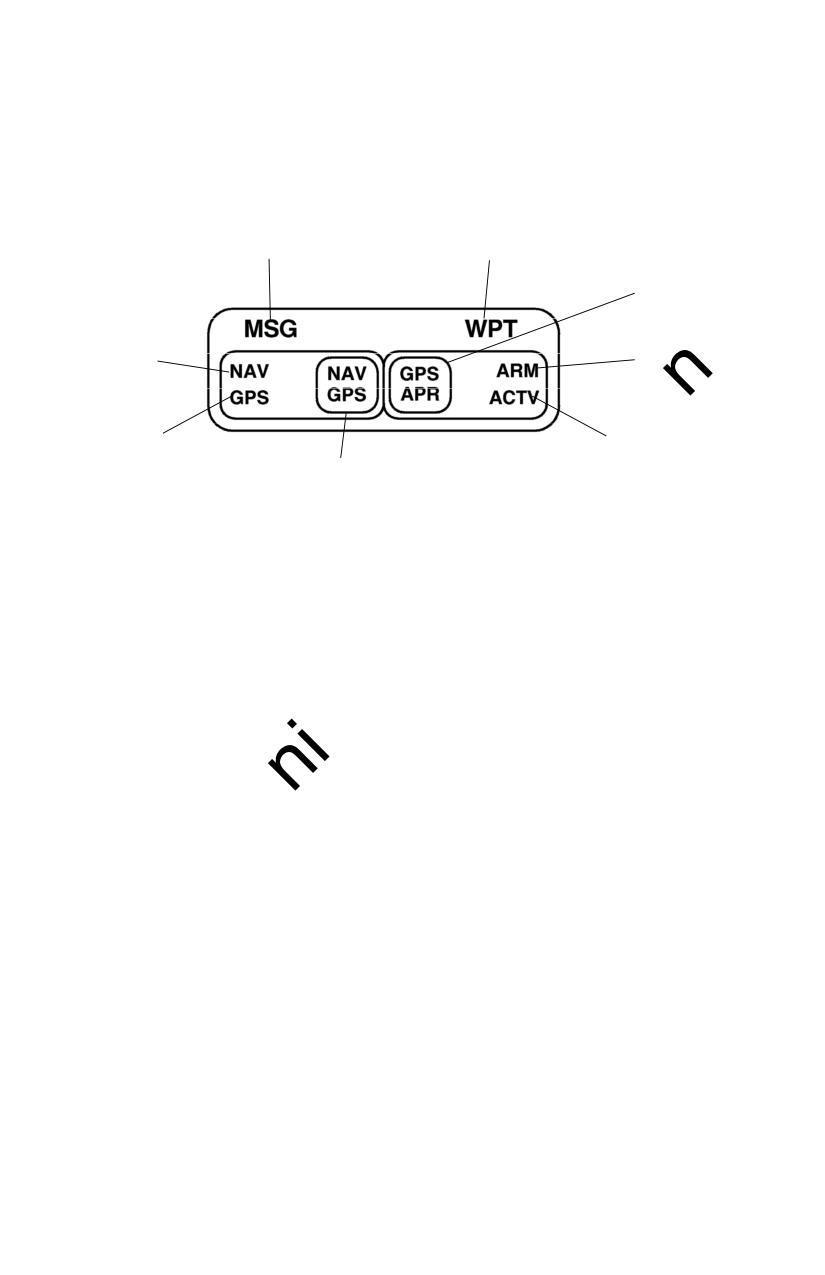
CESSNA
SECTION 9 - SUPPLEMENTS
MODEL 172R
SUPPLEMENT 5 - FAA APPROVED
1
2
3
7
4
8
5
6
0585C1042
1. GPS MESSAGE (MSG) ANNUNCIATOR LIGHT -- MSG will
begin flashing whenever the message prompt (a large "M" on
the left side of the screen) on the KLN 89B GPS unit begins
flashing to alert the pilot that a message is waiting. Press the
Message (MSG) key on the GPS to display the message. If a
message condition exists which requires a specific action by
the pilot, the message annunciator will remain on but will not
flash.
2. GPS WAYPOINT (WPT) ANNUNCIATOR LIGHT
-- GPS
WAYPOINT annunciator will begin to flash approximately 36
seconds prior to reaching a Direct-To waypoint. Also, when
turn anticipation is enabled in the KLN 89B GPS unit, the
annunciator will begin to flash
20 seconds prior to the
beginning of turn anticipation, then illuminate steady at the
very beginning of turn anticipation.
Figure 1. GPS Annunciator/Switch (Sheet 1 of 3)
July 15/98
S5-7
l
SECTION 9 - SUPPLEMENTS
CESSNA
SUPPLEMENT 5 - FAA APPROVED
MODEL 172R
TURN ANTICIPATION IS AUTOMATICALLY
DISABLED FOR FAF WAYPOINTS AND THOSE
USED EXCLUSIVELY IN SID/STARS WHERE
OVERFLIGHT IS REQUIRED. FOR WAYPOINTS
SHARED
BETWEEN
SID/STARS
AND
PUBLISHED EN ROUTE SEGMENTS (REQUIRING
OVERFLIGHT IN THE SID/STARS), PROPER
SELECTION ON THE PRESENTED WAYPOINT
PAGE IS NECESSARY TO PROVIDE ADEQUATE
ROUTE PROTECTION ON THE SID/STARS.
3.
GPS APPROACH (GPS, APR) SWITCH -- Pressing the GPS
APPROACH switch manually selects or disarms the approach
ARM mode and also cancels the approach ACTV mode after
being automatically engaged by the KLN 89B GPS system.
The white background color of the GPS APPROACH
annunciator makes it visible in daylight.
4.
ARM ANNUNCIATOR LIGHT
-- ARM annunciator will
illuminate when the KLN
89B GPS system automatically
selects the approach ARM mode or when the approach ARM
mode is manually selected. The approach ARM mode will be
automatically selected when the airplane is within 30 NM of an
airport, and an approach is loaded in the flight plan for that
airport. The approach ARM mode can manually be selected
at a greater distance than 30 NM from the airport by pressing
the GPS APPROACH switch; however, this will not change the
CDI scale until the airplane reaches the 30 NM point. The
approach ARM mode can also be disarmed by pressing the
GPS APPROACH switch.
5.
ACTIVE (ACTV) ANNUNCIATOR LIGHT -- ACTV annunciator
will illuminate when the KLN 89B GPS system automatically
engages the approach ACTV mode (the ACTV mode can only
be engaged by the KLN 89B GPS system which is automatic.)
To cancel the approach ACTV mode, press the GPS
APPROACH switch; this will change the mode to the approach
ARM mode and illuminate the ARM annunciator.
Figure 1. GPS Annunciator/Switch (Sheet 2 of 3)
l
S5-8
July 15/98
CESSNA
SECTION 9 - SUPPLEMENTS
MODEL 172R
SUPPLEMENT 5 - FAA APPROVED
6.
NAV/GPS SWITCH -- Toggles from Nav 1 to GPS and vice
versa to control the type of navigation data to be displayed on
the CDI (Course Deviation Indicator). The No. 1 CDI Omni
Bearing Selector (OBS) provides analog course input to the
KLN
89B in OBS mode when the NAV/GPS
switch/annunciator is in GPS. When the NAV/GPS switch
annunciation is in NAV, GPS course selection in OBS mode is
digital through the use of the controls and display at the KLN
89B.
NOTE
Manual CDI course centering in OBS mode using the
control knob can be difficult, especially at long
distances. Centering the Course Deviation Indicator
(CDI) needle can best be accomplished by pressing the
Direct-To button and then manually setting the No. 1
CDI course to the course value prescribed in the KLN
89B displayed message.
NOTE
The Directional Gyro heading (HDG) bug must also be
set to provide proper course datum to the autopilot if
coupled to the KLN 89B in LEG or OBS. (When the
optional HSI is installed, the HSI course pointer provides
course datum to the autopilot.)
7.
NAVIGATION SOURCE (NAV) ANNUNCIATOR -- The NAV
annunciator will illuminate steady to inform the pilot that NAV
1 information is being displayed on the NAV 1 CDI.
8.
NAVIGATION SOURCE (GPS) ANNUNCIATOR -- The GPS
annunciator will illuminate steady to inform the pilot that GPS
information is being displayed on the NAV 1 CDI.
Figure 1. GPS Annunciator/Switch (Sheet 3 of 3)
July 15/98
S5-9
l
SECTION 9 - SUPPLEMENTS
CESSNA
SUPPLEMENT 5 - FAA APPROVED
MODEL 172R
SECTION 2
LIMITATIONS
1.
The KLN 89B GPS Pilot's Guide, P/N 006-08786-0000, dated
May, 1995 (or later applicable revision) must be available to the
flight crew whenever IFR GPS navigation is used.
The
Operational Revision Status (ORS) of the Pilot's Guide must
match the ORS level annunciated on the Self Test page.
2.
IFR Navigation is restricted as follows:
a. The system must utilize ORS level 01 or later FAA approved
revision.
b. The data on the self test page must be verified prior to use.
c. IFR en route and terminal navigation is prohibited unless the
pilot verifies the currency of the database or verifies each
selected waypoint for accuracy by reference to current
approved data.
d. The system must utilize ORS Level 02 or later FAA approved
revision to conduct nonprecision instrument approaches. In
addition, the software level status found on page OTH 6 must
be "HOST 00880-0004" or later. Instrument approaches must
be accomplished in accordance with approved instrument
approach procedures that are retrieved from the KLN 89B
database. The KLN
89B database must incorporate the
current update cycle.
1) The KLN
89B Quick Reference, P/N
006-08787-0000,
dated
5/95 (or later applicable to revision) must be
available to the flight crew during instrument approach
operations.
2) Instrument approaches must be conducted in the approach
mode and RAIM must be available at the Final Approach
Fix.
S5-10
July 15/98
CESSNA
SECTION 9 - SUPPLEMENTS
MODEL 172R
SUPPLEMENT 5 - FAA APPROVED
3) APR ACTV mode must be annunciated at the Final
Approach Fix.
4) Accomplishment of ILS, LOC, LOC-BC, LDA, SDF, and
MLS approaches are not authorized.
5) When an alternate airport is required by the applicable
operating rules, it must be served by an approach based
on other than GPS or Loran-C navigation.
6) The KLN 89B can only be used for approach guidance if
the reference coordinate datum system for the instrument
approach is WGS-84 or NAD-83. (All approaches in the
KLN 89B database use the WGS-84 or the NAD-83
geodetic datum).
e. For BRNAV operations in the European region:
1) With 23 (24 if the altitude input to the KLN 89B is not
available) or more satellites projected to be operational for
the flight, the aircraft can depart without further action.
2) With 22 (23 if the altitude input to the KLN 89B is not
available) or fewer satellites projected to be operational for
the flight, the availability of the GPS integrity (RAIM) should
be confirmed for the intended flight (route and time). This
should be obtained from a prediction program run outside
of the aircraft. The prediction program must comply with
the criteria of Appendix 1 of AC90-96. In the event of a
predicted continuous loss of RAIM of more than 5 minutes
for any part of the intended flight, the flight should be
delayed, cancelled, or rerouted on a track where RAIM
requirements can be met.
NOTE
AlliedSignal's Preflight, Version 2.0 or later computer based
prediction program may be used for the RAIM prediction.
Alternate methods should be submitted for approval in
accordance with Advisory Circular AC90-96.
Mar 15/99
S5-11
SECTION 9 - SUPPLEMENTS
CESSNA
SUPPLEMENT 5 - FAA APPROVED
MODEL 172R
f. The aircraft must have other approved navigation equipment
appropriate to the route of flight installed and operational.
PLACARDS
Use of the KLN 89B without the Operational Revision Status
upgrade to "ORS 02" or later is limited to VFR and IFR enroute
only. The following information must be presented in the form of
placards when the airplane is equipped with a KLN 89B unit that
has not been upgraded.
1. On the instrument panel near the KLN 89B unit:
GPS NOT APPROVED
FOR IFR APPROACH
This placard is not required with an Operational Revision Status
upgrade to "ORS 02" or later as read on the Power-On page and
host software upgrade to "HOST 00880-0004" or later as read on
the OTH 6 page.
SECTION 3
EMERGENCY PROCEDURES
There are no changes to the basic airplane emergency
procedures when the KLN 89B GPS is installed.
1. If the KLN 89B GPS information is not available or invalid, utilize
remaining operational navigation equipment as required.
2. If a "RAIM NOT AVAILABLE" message is displayed while
conducting an instrument approach, terminate the approach.
Execute a missed approach if required.
S5-12
Mar 15/99
CESSNA
SECTION 9 - SUPPLEMENTS
MODEL 172R
SUPPLEMENT 5 - FAA APPROVED
3. If a "RAIM NOT AVAILABLE" message is displayed in the en
route or terminal phase of flight, continue to navigate using the
KLN
89B or revert to an alternate means of navigation
appropriate to the route and phase of flight. When continuing to
use the KLN 89B for navigation, position must be verified every
15 minutes using another IFR approved navigation system.
4. Refer to the KLN 89B Pilot's Guide, Appendices B and C, for
appropriate pilot actions to be accomplished in response to
annunciated messages.
SECTION 4
NORMAL PROCEDURES
OPERATION
Normal operating procedures are outlined in the KLN 89B GPS
Pilot's Guide, P/N 006-08786-0000, dated May, 1995, (or later
applicable revision). A KLN 89B Quick Reference, P/N 006-08787-
0000, dated May, 1995 (or later applicable revision) containing an
approach sequence, operating tips and approach related messages
is intended as well for cockpit use by the pilot familiar with KLN 89B
operations when conducting instrument approaches.
TO PREVENT THE POSSIBILITY OF TURN
ANTICIPATION
CAUSING
POTENTIALLY
MISLEADING
NAVIGATION
WHEN
THE
AIRCRAFT IS NOT ON COURSE, VERIFY THE CDI
COURSE AND CDI NEEDLE PRESENTATION IS
PROPER PRIOR TO TAKEOFF AND DO NOT
SWITCH FROM OBS TO LEG WITH GREATER
THAN 1 NM CROSS TRACK ERROR (XTK).
IF MISLEADING DATA IS SUSPECTED, A
DIRECT-TO OPERATION TO YOUR DESIRED
WAYPOINT WILL CLEAR ANY PREVIOUS OBS
COURSE, AND CANCEL TURN ANTICIPATION.
Mar 15/99
S5-13
l
SECTION 9 - SUPPLEMENTS
CESSNA
SUPPLEMENT 5 - FAA APPROVED
MODEL 172R
NOTE
After the above Direct-To operation, further reorientation to
the nearest leg of the active flight plan may be
accomplished by pressing the Direct-To button followed by
pressing the Clear button and finally the Enter Button.
Refer to the Pilot's Guide section 4.2.2 for an explanation of
turn anticipation, and Appendix A - Navigation Terms for the
definition of cross track error (XTK).
AUTOPILOT COUPLED OPERATION
The KLN 89B may be coupled to the KAP 140 autopilot by first
selecting GPS on the NAV/GPS switch. Manual selection of the
desired track on the pilot's DG heading bug is required to provide
course datum to the KAP 140 autopilot. (Frequent course datum
changes may be necessary, such as in the case of flying a DME
arc.) The autopilot approach mode (APR) should be used when
conducting a coupled GPS approach.
NOTE
Select HDG mode for DME arc intercepts. NAV or APR
coupled DME arc intercepts can result in excessive
overshoots (aggravated by high ground speeds and/or
intercepts from inside the arc).
APPROACH MODE SEQUENCING AND RAIM PREDICTION
FAMILIARITY WITH THE EN ROUTE OPERATION
OF THE KLN 89B DOES NOT CONSTITUTE
PROFICIENCY IN APPROACH OPERATIONS. DO
NOT ATTEMPT APPROACH OPERATIONS IN
IMC
(INSTRUMENT
METEOROLOGICAL
CONDITIONS)
PRIOR
TO
ATTAINING
PROFICIENCY IN THE USE OF THE KLN 89B.
l
S5-14
Mar 15/99
CESSNA
SECTION 9 - SUPPLEMENTS
MODEL 172R
SUPPLEMENT 5 - FAA APPROVED
NOTE
The special use airspace alert will automatically be
disabled prior to flying an instrument approach to
reduce the potential for message congestion.
1.
Prior to arrival, select a STAR if appropriate from the APT 7
page. Select an approach and an initial approach fix (IAF)
from the APT 8 page.
NOTE
Using the outer knob, select the ACT (Active Flight Plan
Waypoints) pages. Pull the inner knob out and scroll to
the destination airport, then push the inner knob in and
select the ACT 7 or ACT 8 page.
To delete or replace a SID, STAR or approach, select
FPL 0 page. Place the cursor over the name of the
procedure, press ENT to change it, or CLR then ENT to
delete it.
2.
En route, check for RAIM availability at the destination airport
ETA on the OTH 3 page.
NOTE
RAIM must be available at the FAF in order to fly an
instrument approach. Be prepared to terminate the
approach upon loss of RAIM.
3.
At or within 30 nm from the airport:
a. Verify automatic annunciation of APRARM.
b. Note automatic CDI needle scaling change from ±5.0 nm
to ±1.0 nm over the next 30 seconds.
c. Update the KLN 89B altimeter baro setting as required.
d. Internally the KLN 89B will transition from en route to
terminal integrity monitoring.
Mar 15/99
S5-15
l
SECTION 9 - SUPPLEMENTS
CESSNA
SUPPLEMENT 5 - FAA APPROVED
MODEL 172R
4. Select NAV 4 page to fly the approach procedure.
a. If receiving radar vectors, or need to fly a procedure turn or
holding pattern, fly in OBS until inbound to the FAF.
NOTE
OBS navigation is TO-FROM (like a VOR) without
waypoint sequencing.
TO PREVENT THE POSSIBILITY OF TURN
ANTICIPATION
CAUSING
POTENTIALLY
MISLEADING
NAVIGATION
WHEN
THE
AIRCRAFT IS NOT ON COURSE, DO
NOT
SWITCH FROM OBS TO LEG WITH GREATER
THAN 1 NM CROSS TRACK ERROR (XTK).
b. NoPT routes including DME arc's are flown in LEG. LEG
is mandatory from the FAF to the MAP.
NOTE
Select HDG mode for DME arc intercepts. NAV or APR
coupled DME arc intercepts can result in excessive
overshoots (aggravated by high ground speeds and/or
intercepts from inside the arc).
FLYING FINAL OUTBOUND FROM AN OFF-
AIRPORT
VORTAC
ON
AN
OVERLAY
APPROACH; BEWARE OF THE DME DISTANCE
INCREASING ON FINAL APPROACH, AND THE
GPS DISTANCE-TO-WAYPOINT DECREASING,
AND NOT MATCHING THE NUMBERS ON THE
APPROACH PLATE.
l
S5-16
Mar 15/99
CESSNA
SECTION 9 - SUPPLEMENTS
MODEL 172R
SUPPLEMENT 5 - FAA APPROVED
5.
At or before 2 nm from the FAF inbound:
a. Select the FAF as the active waypoint, if not accomplished
already.
b. Select LEG operation.
6.
Approaching the FAF inbound (within 2 nm):
a. Verify APR ACTV.
b. Note automatic CDI needle scaling change from ±1.0 nm
to ±0.3 nm over the 2 nm inbound to the FAF.
c. Internally the KLN
89B will transition from terminal to
approach integrity monitoring.
7.
Crossing the FAF and APR ACTV is not annunciated:
a. Do not descend.
b. Execute the missed approach.
8.
Missed Approach:
a. Climb.
b. Navigate to the MAP (in APRARM if APR ACTV is not
available).
NOTE
There is no automatic LEG sequencing at the MAP.
c. After climbing in accordance with the published missed
approach procedure, press the Direct To button, verify or
change the desired holding fix and press ENT.
Mar 15/99
S5-17
l
SECTION 9 - SUPPLEMENTS
CESSNA
SUPPLEMENT 5 - FAA APPROVED
MODEL 172R
GENERAL NOTES
• The database must be up to date for instrument approach
operation.
• Only one approach can be in the flight plan at a time.
• Checking RAIM prediction for your approach while en route using
the OTH
3 page is recommended. A self check occurs
automatically within 2 nm of the FAF. APR ACTV is inhibited
without RAIM.
• Data cannot be altered, added to or deleted from the approach
procedures contained in the database. (DME arc intercepts may
be relocated along the arc through the NAV 4 or the FPL 0
pages).
• Some approach waypoints do not appear on the approach
plates (including in some instances the FAF).
• Waypoint suffixes in the flight plan:
i --
IAF
f --
FAF
m -- MAP
h -- missed approach holding fix.
•The DME arc IAF (arc intercept waypoint) will be on your present
position radial off the arc VOR when you load the IAF into the flight
plan, or the beginning of the arc if currently on a radial beyond the
arc limit. To adjust the arc intercept to be compatible with a
current radar vector, bring up the arc IAF waypoint in the NAV 4
page scanning field or under the cursor on the FPL 0 page, press
CLR, then ENT. Fly the arc in LEG. Adjust the heading bug (if
autopilot coupled) and CDI course with reference to the desired
track value on the NAV 4 page (it will flash to remind you).
Left/right CDI needle information is relative to the arc. Displayed
distance is not along the arc but direct to the active waypoint. (The
DME arc radial is also displayed in the lower right corner of the
NAV 4 page.)
l
S5-18
Mar 15/99
CESSNA
SECTION 9 - SUPPLEMENTS
MODEL 172R
SUPPLEMENT 5 - FAA APPROVED
• The DME arc IAF identifier may be unfamiliar. Example: D098G
where 098 stands for the 098° radial off the referenced VOR,
and G is the seventh letter in the alphabet indicating a 7 DME
arc.
• APRARM to APR ACTV is automatic provided that:
a. You are in APRARM (normally automatic).
b. You are in LEG mode.
c. The FAF is the active waypoint.
d. Within 2 nm of the FAF.
e. Outside of the FAF.
f. Inbound to the FAF.
g. RAIM is available.
• Direct-To operation between the FAF and MAP cancels APR
ACTV. Fly the missed approach in APRARM.
• Flagged navigation inside the FAF may usually be restored (not
guaranteed) by pressing the GPS APR button changing from
ACTV to ARM. Fly the missed approach.
• The instrument approach using the KLN 89B may be essentially
automatic starting 30 nm out (with a manual baro setting update)
or it may require judicious selection of the OBS and LEG modes.
• APRARM may be canceled at any time by pressing the GPS APR
button. (A subsequent press will reselect it.)
SECTION 5
PERFORMANCE
There is no change to the airplane performance when this avionics
equipment is installed. However, installation of an externally-
mounted antenna or related external antennas, will result in a minor
reduction in cruise performance.
Mar 15/99
S5-19/(S5-20 blank)
l
Pilot's Operating Handbook and
FAA Approved Airplane Flight Manual
CESSNA MODEL 172R
AIRPLANES 172R80001 AND ON
SUPPLEMENT 6
BENDIX/KING KR87
AUTOMATIC DIRECTION FINDER
SERIAL NO.
REGISTRATION NO.
This supplement must be inserted into Section
9 of the Pilot's Operating
Handbook and FAA Approved Airplane Flight Manual when the Automatic
Direction Finder is installed.
FAA APPROVAL
Date: 3 April 2000
Member of GAMA
2 December 1996
COPYRIGHT ” 1996
CESSNA AIRCRAFT COMPANY
WICHITA, KANSAS, USA
Revision 1 - 28 February 2000
172RPHUS-S6-01
S6-1
SECTION 9 - SUPPLEMENTS
CESSNA
SUPPLEMENT 6 - FAA APPROVED
MODEL 172R
SUPPLEMENT 6
BENDIX/KING KR 87 AUTOMATIC DIRECTION
FINDER (ADF)
The following Log of Effective Pages provides the date of issue
for original and revised pages, as well as a listing of all pages in
the Supplement. Pages which are affected by the current
revision will carry the date of that revision
Revision Level
Date of Issue
0 (Original)
Dec. 2, 1996
1
Feb. 28, 2000
LOG OF EFFECTIVITY PAGES
_______________________________________
PAGE
DATE
PAGE
DATE
Title (S6-1)
Feb 28/00
S6-7
Dec 2/96
S6-2
Feb 28/00
S6-8
Dec 2/96
S6-3
Feb 28/00
S6-9
Dec 2/96
S6-4
Dec 2/96
S6-10
Dec 2/96
S6-5
Dec 2/96
S6-11
Feb 28/00
S6-6
Dec 2/96
S6-12
Dec 2/96
SERVICE BULLETIN CONFIGURATION LIST
The following is a list of Service Bulletins that are applicable to
the operation of the airplane, and have been incorporated into
this supplement. This list contains only those Service Bulletins
that are currently active.
Airplane Unit Revision
Incorporated
Number Title
Effectivity
Incorporation In Airplane
S6-2
Feb 28/00
CESSNA
SECTION 9 - SUPPLEMENTS
MODEL 172R
SUPPLEMENT 6 - FAA APPROVED
SUPPLEMENT
BENDIX/KING KR 87 AUTOMATIC DIRECTION
FINDER (ADF)
SECTION 1
GENERAL
The Bendix/King Digital ADF is a panel-mounted, digitally tuned
automatic direction finder. It is designed to provide continuous 1-
kHz digital tuning in the frequency range of 200-kHz to 1799-kHz
and eliminates the need for mechanical band switching. The
system is comprised of a receiver, a built-in electronics timer, a
bearing indicator, and a KA-44B combined loop and sense antenna.
Operating controls and displays for the Bendix/King Digital ADF are
shown and described in Figure
1. The audio system used in
conjunction with this radio for speaker-phone selection is shown and
described in Supplement 3 of this handbook.
The Bendix/King Digital ADF can be used for position plotting
and homing procedures, and for aural reception of amplitude-
modulated (AM) signals.
The "flip-flop" frequency display allows switching between pre-
selected "STANDBY" and "ACTIVE" frequencies by pressing the
frequency transfer button. Both pre-selected frequencies are stored
in a non-volatile memory circuit (no battery power required) and
displayed in large, easy-to-read, self-dimming gas discharge
numerics. The active frequency is continuously displayed in the left
window, while the right window will display either the standby
frequency or the selected readout from the built-in electronic timer.
The built-in electronic timer has two separate and independent
timing functions. An automatic flight timer that starts whenever the
unit is turned on. This timer functions up to 59 hours and 59
minutes. An elapsed timer which will count up or down for up to 59
minutes and 59 seconds. When a preset time interval has been
programmed and the countdown reaches :00, the display will flash
for 15 seconds. Since both the flight timer and elapsed timer
operate independently, it is possible to monitor either one without
disrupting the other. The pushbutton controls and the bearing
indicators are internally lighted. Intensity is controlled by the RADIO
light dimming rheostat.
Feb 28/00
S6-3

SECTION 9 - SUPPLEMENTS
CESSNA
SUPPLEMENT 6 - FAA APPROVED
MODEL 172R
1
2
3
4
5
6
7
12
11
10
9
8
13
14
16
15
0585C1043
0585C1044
Figure 1. KR 87 Automatic Direction Finder (ADF) (Sheet 1 of 4)
S6-4
Dec 2/96
CESSNA
SECTION 9 - SUPPLEMENTS
MODEL 172R
SUPPLEMENT 6 - FAA APPROVED
1. ANT/ADF MODE ANNUNCIATOR
--
Antenna (ANT) is
selected by the "out" position of the ADF button. This mode
improves the audio reception and is usually used for station
identification. The bearing pointer is deactivated and will park
in the 90° relative position. Automatic Direction Finder (ADF)
mode is selected by the depressed position of the ADF button.
This mode activates the bearing pointer. The bearing pointer
will point in the direction of the station relative to the aircraft
heading.
2. IN-USE FREQUENCY DISPLAY -- The frequency to which the
ADF is tuned is displayed here. The active ADF frequency can
be changed directly when either of the timer functions is
selected.
3. BFO (Beat Frequency Oscillator) ANNUNCIATOR -- The BFO
mode, activated and annunciated when the "BFO" button is
depressed, permits the carrier wave and associated morse
code identifier broadcast on the carrier wave to be heard.
NOTE
CW signals (Morse Code) are unmodulated and no audio
will be heard without use of BFO. This type of signal is not
used in the United States air navigation. It is used in some
foreign countries and marine beacons.
4. STANDBY FREQUENCY/FLIGHT TIME OR ELAPSED TIME
ANNUNCIATION -- When FRQ is displayed the STANDBY
frequency is displayed in the right hand display. The
STANDBY frequency is selected using the frequency select
knobs. The selected STANDBY frequency is put into the
ACTIVE frequency windows by pressing the frequency transfer
button. Either the standby frequency, the flight timer, or the
elapsed time is displayed in this position. The flight timer and
elapsed timer are displayed replacing the standby frequency
which goes into "blind" memory to be called back at any time
by depressing the FRQ button. Flight time or elapsed time are
displayed and annunciated alternatively by depressing the
FLT/ET button.
Figure 1. KR 87 Automatic Direction Finder (ADF) (Sheet 2 of 4)
Dec 2/96
S6-5
SECTION 9 - SUPPLEMENTS
CESSNA
SUPPLEMENT 6 - FAA APPROVED
MODEL 172R
5. FLIGHT TIMER AND ELAPSED TIMER MODE ANNUNCIATION -- Either
the elapsed time (ET) or flight time (FLT) mode is annunciated here.
6.
FREQUENCY SELECT KNOBS -- Selects the standby frequency when
FRQ is displayed and directly selects the active frequency whenever
either of the time functions is selected. The frequency selector knobs
may be rotated either clockwise or counterclockwise. The small knob is
pulled out to tune the 1's. The small knob is pushed in to tune the 10's.
The outer knob tunes the 100's with rollover into the 1000's up to 1799.
These knobs are also used to set the desired time when the elapsed
timer is used in the countdown mode.
7.
ON/OFF/VOLUME CONTROL SWITCH (ON/OFF/VOL)
-- Controls
primary power and audio output level. Clockwise rotation from OFF
position applies primary power to the receiver; further clockwise
rotation increases audio level. Audio muting causes the audio output to
be muted unless the receiver is locked on a valid station.
8.
SET/RESET ELAPSED TIMER BUTTON (SET/RST) -- The set/reset
button when pressed resets the elapsed timer whether it is being
displayed or not.
9.
FLIGHT TIMER/ELAPSED TIMER MODE SELECTOR BUTTON
(FLT/ET) -- The Flight Timer/Elapsed Time mode selector button when
pressed alternatively selects either Flight Timer mode or Elapsed Timer
mode.
10.
FREQUENCY TRANSFER BUTTON (FRQ) -- The FRQ transfer button
when pressed exchanges the active and standby frequencies. The new
frequency becomes active and the former active frequency goes into
standby.
11.
BFO (Beat Frequency Oscillator) BUTTON -- The BFO button selects
the BFO mode when in the depressed position. (See note under item
3).
12.
ADF BUTTON -- The ADF button selects either the ANT mode or the
ADF mode. The ANT mode is selected with the ADF button in the out
position. The ADF mode is selected with the ADF button in the
depressed position.
Figure 1. KR 87 Automatic Direction Finder (ADF) (Sheet 3 of 4
S6-6
Dec 2/96
CESSNA
SECTION 9 - SUPPLEMENTS
MODEL 172R
SUPPLEMENT 6 - FAA APPROVED
13. LUBBER LINE -- Indicates relative or magnetic heading of the
aircraft. The heading must be manually input by the pilot with
the heading (HDG) knob.
14. COMPASS CARD -- Manually rotatable card that indicates
relative or magnetic heading of aircraft, as selected by HDG
knob.
15. BEARING POINTER -- Indicates relative or magnetic bearing
to station as selected by HDG knob. If the relative heading of
North (N) is manually selected under the lubber line by the
pilot, then the bearing pointer indicates the relative bearing to
the station. If the aircraft's magnetic heading is selected
under the lubber line by the pilot, then the bearing pointer
indicates the magnetic bearing to the station.
16. HEADING KNOB (HDG) --Rotates card to set in relative or
magnetic heading of aircraft.
Figure 1. KR 87 Automatic Direction Finder (ADF) (Sheet 4 of 4)
Dec 2/96
S6-7
SECTION 9 - SUPPLEMENTS
CESSNA
SUPPLEMENT 6 - FAA APPROVED
MODEL 172R
SECTION 2
LIMITATIONS
There is no change to airplane limitations when the KR 87 ADF
is installed.
SECTION 3
EMERGENCY PROCEDURES
There are no changes to the basic airplane emergency
procedures when the KR 87 ADF is installed.
SECTION 4
NORMAL PROCEDURES
TO OPERATE AS AN AUTOMATIC DIRECTION FINDER:
1. OFF/VOL Control -- ON.
2. Frequency Selector Knobs -- SELECT desired frequency in
the standby frequency display.
3. FRQ Button -- PRESS to move the desired frequency from the
standby to the active position.
4. ADF Selector Switch (on audio control panel) -- SELECT as
desired.
5. OFF/VOL Control -- SET to desired volume level and identify
that desired station is being received.
6. ADF Button -- SELECT ADF mode and note relative bearing
on indicator.
ADF TEST (PRE-FLIGHT or IN-FLIGHT):
1. ADF Button -- SELECT ANT mode and note pointer moves to
90° position.
2. ADF Button -- SELECT ADF mode and note the pointer moves
without hesitation to the station bearing. Excessive pointer
sluggishness, wavering or reversals indicate a signal that is
too weak or a system malfunction.
S6-8
Dec 2/96
CESSNA
SECTION 9 - SUPPLEMENTS
MODEL 172R
SUPPLEMENT 6 - FAA APPROVED
TO OPERATE BFO:
1. OFF/VOL Control -- ON.
2. BFO Button -- PRESS on.
3. ADF Selector Buttons (on audio control panel) -- SET to
desired mode.
4. VOL Control -- ADJUST to desired listening level.
NOTE
A 1000-Hz tone and Morse Code identifier is heard in
the audio output when a CW signal is received.
TO OPERATE FLIGHT TIMER:
1. OFF/VOL Control -- ON.
2. FLT/ET Mode Button -- PRESS (once or twice) until FLT is
annunciated. Timer will already be counting since it is
activated by turning the unit on.
3. OFF/VOL Control -- OFF and then ON if it is desired to reset
the flight timer.
TO OPERATE AS A COMMUNICATIONS RECEIVER ONLY:
1. OFF/VOL Control -- ON.
2. ADF Button -- SELECT ANT mode.
3. Frequency Selector Knobs -- SELECT desired frequency in
the standby frequency display.
4. FRQ Button -- PRESS to move the desired frequency from the
standby to the active position.
5. ADF Selector Buttons (on audio control panel) -- SET to
desired mode.
6. VOL Control -- ADJUST to desired listening level.
Dec 2/96
S6-9
SECTION 9 - SUPPLEMENTS
CESSNA
SUPPLEMENT 6 - FAA APPROVED
MODEL 172R
TO OPERATE ELAPSED TIME TIMER-COUNT UP MODE:
1. OFF/VOL Control -- ON.
2. FLT/ET Mode Button -- PRESS (once or twice) until ET is
annunciated.
3. SET/RST Button -- PRESS momentarily to reset elapsed timer
to zero.
NOTE
The Standby Frequency which is in memory while Flight
Time or Elapsed Time modes are being displayed may
be called back by pressing the FRQ button, then
transferred to active use by pressing the FRQ button
again.
TO OPERATE ELAPSED TIME TIMER-COUNT DOWN MODE:
1. OFF/VOL Control -- ON.
2. FLT/ET Mode Button -- PRESS (once or twice) until ET is
annunciated.
3. SET/RST Button -- PRESS until the ET annunciation begins to
flash.
4. FREQUENCY SELECTOR KNOBS -- SET desired time in the
elapsed time display. The small knob is pulled out to tune the
1's. The small knob is pushed in to tune the 10's. The outer
knob tunes minutes up to 59 minutes.
NOTE
Selector knobs remain in the time set mode for
15
seconds after the last entry or until the SET/RST,
FLT/ET or FRQ button is pressed.
5. SET/RST Button -- PRESS to start countdown. When the
timer reaches 0, it will start to count up as display flashes for
15 seconds.
NOTE
While FLT or ET are displayed, the active frequency on
the left side of the window may be changed, by using
the frequency selector knobs, without any effect on the
stored standby frequency or the other modes.
S6-10
Dec 2/96
CESSNA
SECTION 9 - SUPPLEMENTS
MODEL 172R
SUPPLEMENT 6 - FAA APPROVED
ADF OPERATION NOTES:
ERRONEOUS ADF BEARING DUE TO RADIO FREQUENCY
PHENOMENA:
In the U.S., the FCC, which assigns AM radio frequencies,
occasionally will assign the same frequency to more than one
station in an area. Certain conditions, such as Night Effect, may
cause signals from such stations to overlap. This should be taken
into consideration when using AM broadcast station for navigation.
Sunspots and atmospheric phenomena may occasionally distort
reception so that signals from two stations on the same frequency
will overlap. For this reason, it is always wise to make positive
identification of the station being tuned, by switching the function
selector to ANT and listening for station call letters.
ELECTRICAL STORMS:
In the vicinity of electrical storms, an ADF indicator pointer tends
to swing from the station tuned toward the center of the storm.
NIGHT EFFECT:
This is a disturbance particularly strong just after sunset and just
after dawn. An ADF indicator pointer may swing erratically at these
times. If possible, tune to the most powerful station at the lowest
frequency. If this is not possible, take the average of pointer
oscillations to determine relative station bearing.
MOUNTAIN EFFECT:
Radio waves reflecting from the surface of mountains may cause
the pointer to fluctuate or show an erroneous bearing. This should
be taken into account when taking bearings over mountainous
terrain.
COASTAL REFRACTION:
Radio waves may be refracted when passing from land to sea or
when moving parallel to the coastline. This also should be taken
into account.
Feb 28/00
S6-11
SECTION 9 - SUPPLEMENTS
CESSNA
SUPPLEMENT 6 - FAA APPROVED
MODEL 172R
SECTION 5
PERFORMANCE
There is no change to the airplane performance when this
avionic equipment is installed. However, the installation of an
externally mounted antenna or related external antennas, will result
in a minor reduction in cruise performance.
S6-12
Dec 2/96
Pilot's Operating Handbook and
FAA Approved Airplane Flight Manual
CESSNA MODEL 172R
AIRPLANES 172R80001 AND ON
SUPPLEMENT 7
BENDIX/KING KAP 140
SINGLE AXIS AUTOPILOT
SERIAL NO.
REGISTRATION NO.
This supplement must be inserted into Section
9 of the Pilot's Operating
Handbook and FAA Approved Airplane Flight Manual when the KAP 140 Single
Axis Autopilot is installed.
FAA APPROVAL
Date: 3 April 2000
Member of GAMA
2 DECEMBER 1996
COPYRIGHT ” 1996
CESSNA AIRCRAFT COMPANY
WICHITA, KANSAS, USA
Revision 4 - 31 October 2002
172RPHUS-S7-04
S7-1
SECTION 9 - SUPPLEMENTS
CESSNA
SUPPLEMENT 7 - FAA APPROVED
MODEL 172R
SUPPLEMENT 7
BENDIX/KING KAP 140
SINGLE AXIS AUTOPILOT
Use the Log of Effective Pages to determine the current status of
this supplement. Pages affected by the current revision are
indicated by an asterisk (*) preceeding the page number.
Supplement Status
Date
Original Issue
2 December 1996
Revision 1
28 February 1997
Revision 2
3 November 1997
Revision 3
28 February 2000
Revision 4
31 October 2002
LOG OF EFFECTIVE PAGES
Page
Page
Revision
Status
Number
* Title (S7-1)
Revised
4
* S7-1 thru S7-5
Revised
4
S7-6 thru S7-7
Revised
3
* S7-8 thru S7-19
Revised
4
* S7-20
Added
4
S7-2
Revision 4
CESSNA
SECTION 9 - SUPPLEMENTS
MODEL 172R
SUPPLEMENT 7 - FAA APPROVED
SUPPLEMENT 7
BENDIX/KING KAP 140
SINGLE AXIS AUTOPILOT
SERVICE BULLETIN CONFIGURATION LIST
The following is a list of Service Bulletins that are applicable to the
operation of the airplane, and have been incorporated into this
supplement. This list contains only those Service Bulletins that are
currently active.
Airplane
Serial
Revision
Incorporated
Number
Title
Effectivity
Incorporation
In Airplane
KC-140-M1
KAP 140 AP
Revision 4
(Honeywell
Service Bulletin)
Revision 4
S7-3/(S7-4 blank)
CESSNA
SECTION 9 - SUPPLEMENTS
MODEL 172R
SUPPLEMENT 7 - FAA APPROVED
SUPPLEMENT 7
BENDIX/KING KAP 140
SINGLE AXIS AUTOPILOT
SECTION 1
GENERAL
The Bendix/King KAP 140 is an all-electric, single-axis (aileron
control) autopilot system that provides lateral and directional control.
Components are a computer, a turn coordinator, an aileron actuator,
a course deviation indicator, and a directional indicator or HSI (if
installed).
Roll and yaw motions of the airplane are sensed by the turn
coordinator gyro. The computer computes the necessary correction
and signals the actuator to move the ailerons to maintain the
airplane in the commanded lateral attitude.
The KAP 140 will provide wing leveler, heading hold, NAV track,
and approach and backcourse lateral modes.
A lockout device prevents autopilot engagement until the system
has been successfully preflight tested. Automatic preflight self-test
begins with initial power application to the autopilot.
The following conditions will cause the autopilot to disengage:
A. Electric power failure.
B. Internal autopilot system failure.
C. Turn coordinator failure (flagged gyro).
D. Computer autopilot monitor that detects the R (ROLL) axis
annunciator.
The AVIONICS MASTER switch supplies power to the avionics bus
bar at the radio circuit breakers and the autopilot circuit breaker.
The AVIONICS MASTER switch also services as an emergency
autopilot (AP) shutoff.
Revision 4
S7-5
SECTION 9 - SUPPLEMENTS
CESSNA
SUPPLEMENT 7 - FAA APPROVED
MODEL 172R
The following circuit breakers are used to protect the listed elements
of the KAP 140 single axis autopilot:
LABEL
FUNCTIONS
AUTO
Supplies power to the KC 140
PILOT
Computer and the autopilot.
WARN
Supplies power to the autopilot
disconnect tone.
S7-6
Revision 3

CESSNA
SECTION 9 - SUPPLEMENTS
MODEL 172R
SUPPLEMENT 7 - FAA APPROVED
NAV/COMM 1
CONTROL PANEL
GPS
HORIZONTAL
SITUATION
INDICATOR
9
NAVIGATION
SOURCE
SELECTOR
SWITCH
CONTROL
WHEEL
DIRECTIONAL
INDICATOR
NAV 1
AILERON
7
TURN
COORDINATOR
8
ACTUATOR
AUTOPILOT
COMPUTER
CIRCUIT
10
BREAKER
AVIONICS
CIRCUIT
1
BREAKER
BUS
2
3
4
5
6
11
ELECTRICAL
BUS
05851054
Figure 1. Bendix/King KAP 140 Autopilot, Operating Controls
and Indicators (Sheet 1 of 3)
Revision 3
S7-7

SECTION 9 - SUPPLEMENTS
CESSNA
SUPPLEMENT 7 - FAA APPROVED
MODEL 172R
12
1
2
3
4
5
6
1. ROLL (R) AXIS ANNUNCIATOR -- When illuminated, indicates
a failure in the roll axis and prevents engagement or
disengages the autopilot.
2. AUTOPILOT ENGAGE/DISENGAGE (AP) BUTTON -- When
pushed* or pressed and held (approx
0.25 seconds)**,
engages autopilot if all preflight self test conditions are met.
The autopilot will engage in the basic ROL mode which
functions as a wings leveler. The AP button can also be used
to disengage the autopilot.
3. HEADING (HDG) MODE SELECTOR BUTTON
-- When
pushed, will select the Heading mode, which commands the
airplane to turn to and maintain the heading selected by the
heading bug on the Directional Gyro or HSI (if installed). A
new heading may be selected at any time and will result in the
airplane turning to the new heading. The button can also be
used to toggle between HDG and ROL modes. This button
can also be used to engage the autopilot in HDG mode. For
airplane serials 17280001 thru 17281118 not incorporating
Honeywell Service Bulletin KC140-M1, this button will also
engage the autopilot in HDG mode.
* Airplane serials
17280001 thru
17281118 not incorporating
Honeywell Service Bulletin KC140-M1.
** Airplane serials
17280001 thru
17281118 incorporating
Honeywell Service Bulletin KC140-M1, and airplane serials
17281119 and on.
Figure 1. Bendix/King KAP 140 Autopilot, Operating Controls and
Indicators (Sheet 2 of 3)
S7-8
Revision 4
CESSNA
SECTION 9 - SUPPLEMENTS
MODEL 172R
SUPPLEMENT 7 - FAA APPROVED
4.
NAVIGATION (NAV) MODE SELECTOR BUTTON -- When
pushed, will select the Navigation mode. This mode provides
automatic beam capture and tracking of VOR, LOC, or GPS
signals as selected for presentation on the NAV#1 CDI or HSI
(if installed).
5.
APPROACH (APR) MODE SELECTOR BUTTON -- When
pushed, will select the Approach mode. This mode provides
automatic beam capture and tracking of VOR, LOC, or GPS
signals as selected for presentation on the NAV #1 CDI or HSI
(if installed). The greater tracking sensitivity of the APR mode
is recommended for instrument approaches.
6.
BACK COURSE APPROACH (REV) MODE SELECTOR
BUTTON -- This button is active only when the coupled
navigation receiver is tuned to a LOC/ILS frequency. When
pushed, it will select the Back Course (BC) approach mode.
This mode functions indentically to the approach mode except
that the autopilot response to LOC signals is reversed.
7.
HEADING SELECT KNOB (HDG) -- Positions the heading
pointer ("bug") on the compass card. Note that the position of
the heading bug also provides course datum to the autopilot
when tracking in NAV, APR, or REV (BC) modes. This is in
addition to its more intuitive use in the HDG mode.
8.
OMNI BEARING SELECT KNOB (OBS) -- Selects the desired
course radial to be tracked by the autopilot. (Note that the
HDG bug must also be positioned to the proper course to
capture and track the selected radial).
9.
AUTOPILOT DISCONNECT (A/P DISC) SWITCH -- When
depressed will disengage the autopilot.
The autopilot
disconnect will be annunciated by a continuous two-second
tone accompanied by a flashing "AP" displayed on the
autopilot computer.
10. AUTOPILOT CIRCUIT BREAKER -- A 5-amp circuit breaker
supplying 28 VDC to the KAP 140 system.
Figure 1. Bendix/King KAP 140 Autopilot, Operating Controls and
Indicators (Sheet 3 of 3)
Revision 4
S7-9
I
SECTION 9 - SUPPLEMENTS
CESSNA
SUPPLEMENT 7 - FAA APPROVED
MODEL 172R
11.WARN C/B -- Power to the autopilot disconnect horn.
12.AUTOPILOT ENGAGE
Annunciation** -- Illuminates
AP
whenever the autopilot is engaged. Flashes during pilot
initiated or automatic disengagement.
*
Airplane serials
17280001 thru
17281118 not incorporating
Honeywell Service Bulletin KC140-M1.
**
Airplane serials
17280001 thru
17281118 incorporating
Honeywell Service Bulletin KC140-M1, and airplane serials
17281119 and on.
SECTION 2
LIMITATIONS
The following autopilot limitations must be adhered to:
1. The autopilot must be OFF during takeoff and landing.
2. During autopilot operation, the pilot, with seat belt fastened,
must be seated in the left front seat.
3. Continued autopilot system use is prohibited following
abnormal or malfunctioning operation, and prior to corrective
maintenance.
4. The entire PREFLIGHT procedure, outlined under Section 4,
including steps 1 through 6, must be successfully completed
prior to each flight. Use of the autopilot is prohibited prior to
completion of these tests.
5. KMA
28 audio amplifier PUSH OFF/EMG operation is
prohibited during normal operations.
NOTE
During emergency operation of the audio amplifier, the
PUSH OFF/EMG state of the KMA 28 will prevent flight
control system alerts from being heard.
I
S7-10
Revision 4
CESSNA
SECTION 9 - SUPPLEMENTS
MODEL 172R
SUPPLEMENT 7 - FAA APPROVED
SECTION 3
EMERGENCY PROCEDURES
The two step procedure listed under paragraph 1 should be
among the basic airplane emergency procedures that are
committed to memory. It is important that the pilot be proficient
in accomplishing both steps without reference to this manual.
1. In case of Autopilot malfunction (accomplish Items a. and b.
simultaneously):
a. Airplane Control Wheel
-- GRASP FIRMLY and regain
aircraft control.
b. A/P DISC Switch -- PRESS and HOLD throughout recovery.
NOTE
The AVIONICS MASTER switch may be used as an
alternate means of removing power from the autopilot. In
addition to the above, power may be removed with the
Engage/Disengage button or the airplane MASTER switch. If
necessary perform steps a. and b. above, then turn off the
AVIONICS MASTER switch. Primary attitude, airspeed,
directional and altitude control instruments will remain
operational with either master switch OFF.
f DO NOT ATTEMPT TO RE-ENGAGE THE
AUTOPILOT FOLLOWING AN AUTOPILOT
MALFUNCTION.
f THE
PILOT
IN
COMMAND
MUST
CONTINUOUSLY MONITOR THE AUTOPILOT
WHEN IT IS ENGAGED, AND BE PREPARED TO
DISCONNECT THE AUTOPILOT AND TAKE
IMMEDIATE CORRECTIVE ACTION - INCLUDING
MANUAL CONTROL OF THE AIRPLANE
AND/OR PERFORMANCE OF EMERGENCY
PROCEDURES - IF AUTOPILOT OPERATION IS
NOT AS EXPECTED OR IF AIRPLANE CONTROL
IS NOT MAINTAINED.
Revision 4
S7-11
I
SECTION 9 - SUPPLEMENTS
CESSNA
SUPPLEMENT 7 - FAA APPROVED
MODEL 172R
AMPLIFIED EMERGENCY PROCEDURES
The following paragraphs are presented to supply additional
information for the purpose of providing the pilot with a more
complete understanding of the recommended course of action for
an emergency situation.
DO NOT ATTEMPT TO RE-ENGAGE THE
AUTOPILOT FOLLOWING AN AUTOPILOT
MALFUNCTION UNTIL CORRECTIVE SERVICE
ACTION HAS BEEN PERFORMED ON THE
SYSTEM.
An autopilot malfunction occurs when there is an uncommanded
deviation in the airplane flight path or when there is abnormal
control wheel movement. The main concern in reacting to an
autopilot malfunction, or to an automatic disconnect of the autopilot,
is in maintaining control of the airplane. Immediately grasp the
control wheel and press and hold down the A/P DISC switch
throughout the recovery. Manipulate the controls as required to
safely maintain operation of the airplane within all of its operating
limitations.The AVIONICS MASTER switch may be used as required
to remove all power from the Autopilot. With the AVIONICS
MASTER switch off, all flight instruments will remain operational;
however, communications, navigation, and identification equipment
will be inoperative.
Note that the emergency procedure for any malfunction is
essentially the same: immediately grasp the control wheel and
regain airplane control while pressing and the holding the A/P DISC
switch down.
It is important that all portions of the autopilot system are preflight
tested prior to each flight in accordance with the procedures
published herein in order to assure their integrity and continued safe
operation during flight.
A flashing mode annunciation on the face of the autopilot is
normally an indication of mode loss.
I
S7-12
Revision 4
CESSNA
SECTION 9 - SUPPLEMENTS
MODEL 172R
SUPPLEMENT 7 - FAA APPROVED
NOTE
An exception to this is HDG annunciation which will flash for
5 seconds along with steady NAVARM, APRARM, or
REVARM annunciation to remind the pilot to set the HDG
bug for course datum use.
1. Flashing HDG -- Indicates a failed heading. PRESS HDG
button to terminate flashing. ROL will be displayed.
2. Flashing NAV, APR or REV -- Indicates a flagged navigation
source. If no NAV source is flagged, a failed heading mode
can be the cause. PRESS NAV, APR or REV button to
terminate flashing. ROL will be displayed.
NOTE
At the onset of mode annunciator flashing, the autopilot
has already reverted to a default mode of operation,
(i.e., ROL mode). An immediate attempt to reengage
the lost mode may be made if the offending navigation
flag has cleared.
Effects of instrument losses upon autopilot operation:
1. Loss of the artificial horizon -- no effect on the autopilot.
2. Loss of the turn coordinator -- autopilot inoperative.
3. Loss of the Directional Gyro (DG) -- The directional gyro does
not provide any system valid flag. If the DG fails to function
properly the autopilot heading and navigation mode will not
function correctly. Under these conditions, the only useable
lateral mode is ROL.
4. Loss of Horizontal Situation Indicator (HSI) (if installed) -- If the
HSI fails to function properly the autopilot heading and
navigation mode will not function correctly. Under these
conditions, the only usable lateral mode is ROL.
Revision 4
S7-13
I
SECTION 9 - SUPPLEMENTS
CESSNA
SUPPLEMENT 7 - FAA APPROVED
MODEL 172R
SECTION 4
NORMAL PROCEDURES
PREFLIGHT (PERFORM PRIOR TO EACH FLIGHT):
1. GYROS -- Allow time for the turn coordinator to come up to
speed, as evidenced by the turn coordinator flag being pulled
from view.
2. AVIONICS MASTER -- ON.
3. POWER APPLICATION AND SELF TEST
A self test is performed upon power application to the
computer. This test is a sequence of internal checks that
validate proper system operation prior to allowing normal
system operation. The sequence is indicated by "PFT" (pre-
flight test) with an increasing number for the sequence steps.
Successful completion of self test is identified by all display
segments being illuminated (Display Test) and the disconnect
tone sounding.
4. AUTOPILOT -- ENGAGE by pressing AP button.
5. FLIGHT CONTROLS -- MOVE left and right to verify that the
autopilot can be overpowered.
NOTE
Normal use will not require the autopilot to be overpowered.
6. A/P DISC Switch
-- PRESS. Verify that the autopilot
disconnects and tone sounds.
BEFORE TAKEOFF:
1. Autopilot -- OFF.
AUTOPILOT ENGAGEMENT:
1. AP Button -- PRESS. Note ROL annunciator on. If no other
modes are selected the autopilot will operate in the ROL
mode.
NOTE
Aircraft heading may change in ROL mode due to
turbulence.
I
S7-14
Revision 4
CESSNA
SECTION 9 - SUPPLEMENTS
MODEL 172R
SUPPLEMENT 7 - FAA APPROVED
AUTOPILOT ENGAGEMENT:
1. AP Button -- PRESS. Note ROL annunciator on. If no other
modes are selected the autopilot will operate in the ROL
mode.
NOTE
Aircraft heading may change in ROL mode due to
turbulence.
HEADING HOLD
1. Heading Selector Knob -- SET bug to desired heading.
2. HDG Mode Selector Button -- PRESS. Note HDG mode
annunciator ON. Autopilot will automatically turn the aircraft to
the selected heading.
COMMAND TURNS (HEADING HOLD MODE ENGAGED)
1. Heading Selector Knob -- MOVE bug to the desired heading.
Autopilot will automatically turn the aircraft to the new selected
heading.
NAV COUPLING
1. When equipped with DG:
a. NAV#1 OBS Knob -- SELECT desired course.
b. NAV Mode Selector Button -- PRESS. Note NAVARM
annunciated.
c. Heading Selector Knob -- ROTATE BUG to agree with OBS
course.
NOTE
When NAV is selected, the autopilot will flash HDG for 5
seconds to remind the pilot to reset the HDG bug to the
OBS course. If HDG mode was in use at the time of NAV
button selection, a
45° intercept angle will then be
automatically established based on the position of the bug.
Revision 4
S7-15
I
//////////////////////////////////////////