Military reference books and manuals (2009-2023, Volume 7) - page 36
Chapter 10
ERECTOR ASSEMBLY
10-25. Ensure air hose fitting on erector assembly does not get caught in brake-box mounting cup. Insert base
of erector assembly into mounting cup on top of brake box, while aligning air-hose fitting into slot. Push down
until firmly seated. Repeat for second erector assembly. Open all bump-module lids. If a bump-module lid
falls off, align lid hinge over hinge slots in bump assembly and stamp down on hinge to connect the two pieces.
Connector end must be on the outside of the bump-end module. Make sure excess length of 30-foot
interconnect control cable is on the same side as control box.
10-26. Determine where control box will be located. Starting at the side opposite the control box, push
connector end of 30-foot interconnect control cable down through top hole and out through side hole in the
bump end module. Align the end of the 30-foot interconnect control cable with the erector assembly connection.
Push both together to connect. Lay the 30-foot inter-connect control cable into channel one (1).
10-27. Push the other connector end of the 30-foot inter-connect control cable through two (2) holes in the
other bump end module and over the top of the anchor cable. Connect one (1) end of the 6-foot inter-connect
control cable to the erector assembly connection that is on the same side as the control box. Use steady and
constant strokes at a moderate pace when using the air pump or it may burn up.
10-28. Unscrew the cap from the fill valve on the air-bottle assembly. Set the cap aside. Screw the air pump
valve onto the fill value. Use air pump to pressurize each air bottle so that the valve assembly gauge reads a
minimum of 120 psi, but not more than 130 psi. When checking air pressure, always use the gauge on the valve
assembly.
10-29. Unscrew the air-pump valve from the valve assembly and remove the air pump. Place the screw cap
back on and fill valve. If pressure in the air pump needs releasing, press the valve stem pin. Pump the air pump
a few times to cool it.
INSTALL CONTROL SYSTEM
10-30. Excess cable length will allow the control box to be positioned a safe distance (approximately 6 ft.)
away from the brake box. Align free end of the 30-foot and six-foot inter-connect cables with a 3-pin connector
on the control box. Push down to connect. Both of the 3-pin connectors on the control box are the same.
10-31. Align one end of the 300-foot pendant control cable with connector on the end of the pendant. Push
together to connect. Align free end of 300-foot pendant control cable with two-pin connector on control box and
push down to connect it to the two-pin connector.
10-32. If the 300-foot control cable has been unrolled from the cable reel to allow the pendant to be at a
distance from the control box, bury any excess length to prevent a tripping hazard. If this is not possible, mark
or flag the cable with a prominent material (police barrier plastic tape/engineer tape).
Warning: Ensure all personnel are cleared from the area over the
bump modules and erector assemblies before activating the system.
10-33. Flip up the red switch cover on the pendant. Press and release FIRE switch. The erectors should be
fully extended in approximately two (2) seconds. Close red switch cover on pendant. If erector assemblies do
not function, go to the troubleshooting procedures in TM 5-4240-342-12&P.
NET ASSEMBLY
10-34. Two (2) people are required to install the net assembly. Place plastic bag containing the net in the
middle of the roadway, on the side of bump assembly and away from oncoming traffic. The net is pre-packed in
a plastic bag with two (2) net ends nearest the bag opening. Each person grabs one (1) of the net ends and while
walking away from each other pulls the net out of the bag, and stretches the net across the road. This will avoid
tangling the webbing.
10-6
TC 3-19.5
5 November 2009

Employ Vehicle Barriers and Arresting Devices
10-35. If net is tangled find the top of the horizontal-webbing where the center vertical-webbing joins the
horizontal and diagonal pieces. Follow the horizontal webbing out to the ends, twisting it as needed to lie flat
from end-to-end. Stretch out the net assembly on the roadway. The net should be laid out as follows:
Place the (black) rear-capture line closet to the bump (the black rear-capture line is not attached to
any webbing and has black tape on ends).
The (white) bottom-lateral line is placed next (the white bottom-lateral line is stitched to the three-
inch webbing).
The (pink) front-capture line is placed farthest away from the bump (the webbing at the top of the
net is looped around the front capture line).
10-36. Figure 10-5 illustrates the net assembly.
NET ASSEMBLY
Figure 10-5. Net Assembly
INSTALL LIFT STRINGS
10-37. This procedure requires the erectors to be extended. Without lift strings attached, the erector will not
raise the net upon activation.
10-38. Remove one lift string from plastic bag. Feed one looped end of lift string between the upper-retention
band and erector assembly on the same side as the bump modules on road. Take the other end of the lift string
and place it through the loop. Pull tight to secure lift to upper-retention band on erector assembly.
10-39. Feed the free end of the lift string through the quick link at top of the erector. Attach the loop of free end
of lift string to the large quick link at the top of the net by loosening the quick link nut all the way and inserting
the loop of lift string. Tighten the quick-link-nut finger tight. Repeat steps to install a lift string on the other end
of the net.
10-40. To attach the net assembly to brake-line webbing ensure that five (5) feet of black rear capture line
(approximately double arm span) extends beyond the ratchet block. If it is difficult to use your fingers to open
the ratchet cam, use an available tool, stick or tent pin.
10-41. If there is not five (5) feet, push in on the ratchet cam, to release the tension while pulling out on the
(black) rear-capture line. Release the cam lock back into place. The Rear-capture line should not be able to be
pulled in or out, if cam is locked.
5 November 2009
TC 3-19.5
10-7
Chapter 10
10-42. Grab the center of (black) the rear-capture line and place it in the center of channel two (2) (middle
channel) of bump assembly. Working from the center outward, continue to place the rest of (black) the rear-
capture line in channel two (2) of the bump assembly. Ensure the center of the rear-capture line remains in
center of the bump assembly. Notice that all three (3) connection points (disposable tension link (DTL), rear-
capture line and brake-line slider) have black markings.
10-43. Remove a DTL (approximately 10-inch long black and orange rope with black marking) from plastic
bag. Remove screw-pin from screw pin shackle on brake line slider. Set screw pin aside. Place the end loop of
(black) the rear-capture line and one end of the DTL onto the screw-pin shackle on the brake-line slider. Place
screw pin back in screw pin shackle and finger-tighten.
10-44. Loosen the screw pin in the screw pin shackle connected to the brake box eyebolt on the hinge side of
the bump and attach the free end of the DTL. The Screw pin-shackle connected to the brake-box eyebolt should
now hold one (1) end of the DTL and the anchor cable. Repeat brake box steps for the opposite brake box.
10-45. Run the looped end of (white) bottom lateral line under (black) the rear-capture line, then through the
D-ring on the brake webbing.
(It does not matter which direction the lopped end is placed through D-rings).
Ensure lines are not tangled.
10-46. Loosen the quick-link nut at the top of the net and attached looped end of (white) the bottom lateral line.
Finger-tighten quick-link nut. Ensure that the (pink) front-capture line, lift string, and net do not fall out of
quick link. It should not hold the (pink) front-capture line, lift string, net, and (white) bottom-lateral line.
PACK NET AND FRONT-CAPTURE LINE
10-47. Collapse erectors and verify FIRE switch is off and red-switch cover on pendant is closed. For one-
person operation follow these procedures; Push in vent-valve button to release some pressure. Release button
and then push down on top of erector. Repeat procedure until erector is fully collapsed. Repeat this step for
second erector.
10-48. For two-person operation; Operator #1 pushes in the vent-valve to release pressure while Operator #2
pushes down on top of erector until it is fully collapsed. Repeat this step for the second erector.
10-49. Ensure the (black) rear-capture line is in channel 2. Place center of (white) bottom-lateral line (with wet-
webbing) into the center of channel 3 of the bump assembly. Continue to place the rest of the bottom-lateral
line (with net webbing) into channel 3. Ensure center of bottom lateral line remains in the center of the bump
assembly. Pull ratchet block and large quick link over to each bump-end module. Do not tangle excess line. The
(pink) front-capture line must sit on top of everything in channel 3 to assure proper deployment. Ensure the
center of the webbing always remains in the center of the bump assembly while packing the net.
10-50. Starting at the center of the bump assembly and working outward, start packing net webbing into
channel 3. When all of the webbing is in channel 3, place the center vertical part of webbing with (pink) front-
capture line on top of the webbing already packed in channel 3. Ensure the (pink) front-capture line sits on top
of everything in channel 3 and lines are not tangled. No webbing or lines should be between the lid and channel
wall and sticking out of the lid.
10-51. To prevent webbing and lines from slipping out of channel 3, starting at center of bump assembly and
working outward, close center bump module lid and the two (2) module lids on each side of the center module
as packing of webbing is completed. Before closing the last full-length bump module lid on each end of the
bump assembly, fold over excess capture line and place excess line into channel 2.
10-52. Ensure that the ratchet blocks and the quick link are placed flat in both bump-end and modules so those
lids will close. Lift string must lie on top of all components in bump-end module to ensure proper net
deployment.
10-53. Place ratchet block and quick link on top of excess capture line so that they lay flat in both bump-end
modules. Place lift string on top of all components in both bump-end modules. Ensure DTL’s and lift string exit
through diagonal cutout on the lid of both bump-end modules. Close both bump-end module lids. Pull slack out
of lift strings, tucking excess under lids.
10-8
TC 3-19.5
5 November 2009

Employ Vehicle Barriers and Arresting Devices
10-54. Figures 10-6 and 10-7 illustrate the pack net procedures.
PACK NET
Figure 10-6. Pack Net
PACK NET (CONT.)
Figure 10-7. Pack Net Continued.
10-55. Users of the PVAB system should now conduct a systems test using the detailed procedures described
in the PVAB technical manual. Operators must follow the activation, disassembly, and safety requirements
prescribed in the technical manual. See TM 5-4240-342-12&P.
5 November 2009
TC 3-19.5
10-9

Chapter 10
VEHICLE LIGHT ARRESTING DEVICE SPECIFICATIONS
10-56. The Vehicle Lightweight Arresting Device (VLAD) is a counter-materiel, non-lethal vehicle stopping
device. The VLAD provides a man-transportable and quickly pre-emplaced means of stopping several different
classes of wheeled vehicles. The device is equipped with a unique barbed spike system that can be used in
various scenarios such as at checkpoints, roadblocks, and dismount points to stop and ensnare cars and trucks.
User of the VLAD system should refer to TM 5-4240-536-10 for technical guidance on installation, safety, and
operation. The VLAD NSN is 4240-01-518-4626. Figure 10-8 shows the VLAD system packed ready for
transport.
Figure 10-8. VLAD System Packed for Transport
10-57. The VLAD can be rapidly deployed manually, either by laying it out on the road as shown in Figure 10-
9, or by placing it on the side of the road and simply pulling the lanyards to draw it across when needed. Once
the oncoming vehicle’s tires pass over the spikes, the entire system wraps around one or both front tires and
axle, forcing the vehicle to slow down and come to a complete stop.
10-58. The net is manufactured from high modulus polyethylene fiber called Dyneema. This material is
extremely lightweight and strong and is capable of binding to the axle without slipping or tearing. The netting
configuration allows for kinetic energy absorption, and the spikes are machined from high carbon steel to allow
them to pierce most tires.
10-59. There is no overt concern about significant injury or lethality potential with proper employment of the
VLAD. This device is capable of stopping vehicles with minimal damage and minimal harm to the vehicle
occupants and surrounding personnel. Vehicle engagements with the VLAD may result in minor injuries to
vehicle occupants not wearing a seatbelt. The evaluation was conducted using similar modeling and simulation
and an injury assessment report. Figure 10-9 illustrates the VLAD system deployed across a road.
10-10
TC 3-19.5
5 November 2009

Employ Vehicle Barriers and Arresting Devices
Figure 10-9. VLAD Positioned Across Roadway
VLAD SITE SELECTION
10-60. Since a fast moving vehicle will have a much higher chance of evading the net device, the site selected
should be just after a natural slowing feature to maximize the chance of a successful mission. Typical stopping
distances for medium passenger vehicles and light trucks (less than 2 tons) are shown in Table 10-1.
Table 10-1. Vehicle Stopping Distances
VEHICLE SPEED
TYPICAL STOPPING DISTANCE
30 MPH (48 km/h)
82 ft. (25m)
40 MPH (64 km/h)
118 ft. (36m)
50 MPH (80 km/h)
180 ft. (55m)
10-61. In dry conditions there should be a minimum of 330 ft. (approximately 100m). In wet conditions the
distance should be doubled.
VLAD RAPID DEPLOYMENT
10-62. Once a deployment site has been selected, determine the most likely direction of the threat vehicle.
Using two (2) people, each person grabs a carrying strap or each person grabs a handle on the end of the VLAD
carrying bag. Place carrying bag just off the roadway with arrows marked “Towards Target Vehicle” pointing
towards threat vehicle approach and the pouch marked “Deployment Lanyards” at curb/roadside.
10-63. Using thumb and index finger on each side of the buckle, squeeze both buckle releases together to
unclip outside strap on carrying bag. Repeat for second outside strap. Pull open outside flaps #1 and #2. Pull
open inside flaps #1 and #2. One (1) end of carrying bag is closed with hook and pile closures. To open that
end of the carrying bag, pull the hook and pile closures apart and lay it flat.
10-64. Using two (2) people, one (1) person carefully places both hands under the entire spiked section of the
folded net and lifts it up while the other person pulls the carrying bag out of the way. Set the carrying bag aside
for possible repacking.
5 November 2009
TC 3-19.5
10-11
Chapter 10
10-65. One (1) person lifts the net device while the other person pulls the carrying bag out of the way. Ensure
you save the carrying bag for repacking should the VLAD not be deployed. One (1) person carefully holds the
spiked net in place as the other person grabs the two (2) yellow tabs on the other end of the net and walks away
pulling the net until it is unfolded. Net should be parallel with the roadside.
10-66. Using two (2) people, each person grabs a red deployment handle and pulls the net device across the
road approximately at a 45 degree angle (See illustration below). The barbed spikes on the leading edge of the
net should be upright and net should be pulled tight. Do not remove plastic covers over barbed spikes. They
are designed to crush down and expose the spikes when a tire runs over them.
10-67. If necessary and time allows, reposition the net and make sure the net is as flat as possible to avoid
being detected by threat vehicle. Do not step on barbed spikes. Stand clear of the area.
10-68. If the VLAD was deployed but not used to stop a vehicle, repack the net device. Refer to the technical
manual for repacking instructions.
VLAD LANYARD DEPLOYMENT
10-69. Lanyard deployment procedures are the same as rapid deployment with the additional steps of removing
two (2) plastic bags from the pouch on the outside of the carrying bag marked “Deployment Lanyards”.
Remove two (2) plastic anchor pegs, two (2) anchor lanyards, and two (2) deployment lanyards from plastic
bags. Place empty plastic bags back in pouch for possible re-use. Set carrying bag aside for possible repacking.
10-70. To anchor the net device, determine if there are soft edges at the side of the road. If there are use the two
plastic anchor pegs to secure the net device. Insert a plastic anchor peg through the grommet in each of the two
(2) white straps on the end of the net. Push plastic anchor pegs into the ground. Do not hammer in or force in
too deeply.
10-71. If there are no soft edges at the side of the road, Clip an anchor lanyard/strap to the buckle at the end of
the white strap at each side of the net. Run one (1) of the anchor lanyards out to a softer area at a 45 degree
angle (approx.). Insert an anchor peg into one (1) of the three (3) pre-sewn anchor peg loops on the anchor
lanyard. Using hands, push anchor peg into ground ensuring loop is securely under the anchor peg hooks on the
top of the anchor peg. Do not hammer in or force in too deeply. Repeat at other side of net.
10-72. Clip a deployment lanyard to the buckle at the end of the two red deployment handles on the net device.
Using two (2) people, each person grabs an end of a deployment lanyard and walks it to the opposite side of the
road at a 45 degree angle (approx.). Do not unfold the net at this time.
10-73. From a hidden vantage point, each person loosely holds the end of a deployment lanyard and awaits a
target vehicle. DO NOT wrap end of deployment lanyard around hands or fingers.
10-74. Just before target vehicle approaches, both people quickly pull deployment lanyards across the road and
immediately release the lanyards. Stand clear of area in case target vehicle makes evasive maneuvers or tries to
avoid the VLAD.
10-75. Once the vehicle has stopped, quickly gain control of the occupants. Use caution when approaching the
vehicle.
REMOVE NET FROM VEHICLE
10-76. Avoid unnecessary handling of the net device to prevent hand injury from barbed spikes. Wear leather
gloves and do not step on barbed spikes on the leading edge of the net. Use a sharp knife to remove the bulk of
the net from vehicle tires.
10-77. Dispose of any remaining netting to prevent unauthorized re-use. The vehicle will be incapacitated and
must be recovered in accordance with local vehicle recovery procedures.
10-78. The VLAD is a one time use item. However, if the system was deployed but not used to stop a vehicle,
perform the repacking instruction described in TM 5-4240-536-10.
10-12
TC 3-19.5
5 November 2009
Employ Vehicle Barriers and Arresting Devices
RAPID DEPLOY VEHICLE DENIAL SYSTEMS
10-79. Quick deployment vehicle denial systems can be useful supplements for permanent or portable barriers
or other vehicle arresting devices such as PVAB and VLAD. Devices such as the magnum spike system and
caltrops are easily deployed and recovered and very effective against most threat vehicles.
MAGNUM SPIKE SYSTEM
10-80. The Magnum Spike System comes in a carrying case that deploys 160 uniquely designed spikes
configured in rows along a 16 foot mat. The system comes with 45 feet of deployment cord on a reel with press
button release and quick rewind. Spikes are designed for large air escape and engineered to stop and cut up all
types and sizes of tires including run-flats. Clog-proof spikes will withstand multiple high speed impacts.
Included are 50 replacement spikes with holder retainers that can be changed in the field with no tools required.
10-81. The system is simply unrolled from a safe distance across a designated area in front of a threat vehicle.
Figure 10-10 illustrates the Magnum Spike System.
Figure 10-10. Magnum Spike System
CALTROPS
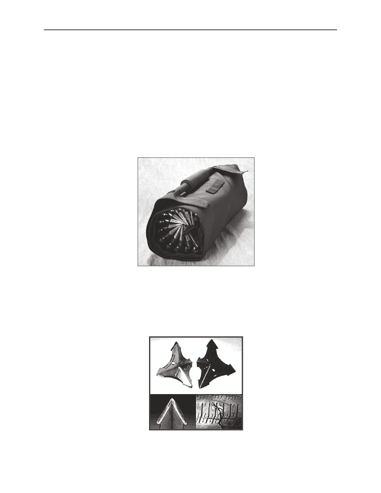
10-82. Caltrops can be hand-scattered and when employed, always land with the point up. They are “V” shape
by design to ensure rapid tire deflation, incapacitating the target vehicle. Caltrops are used for vehicle denial,
and they supplement permanent or portable barriers or other arresting devices like the PVAB or VLAD. Several
Caltrops strung together can be used alone at a hasty checkpoint. Figure 10-11 illustrates typical caltrops.
Figure 10-11. Caltrops
5 November 2009
TC 3-19.5
10-13
This page intentionally left blank.

Chapter 11
Employ Communication Devices
OVERVIEW
11-1. The techniques described in this chapter are used to employ the Phraselator, Voice Response Translator
(VRT), and Magnetic Audio Device (MAD). The Phraselator and VRT translate English to another language,
providing a means of communications between people who lack a common language. The MAD amplifies
sound, which allows the user to talk to a multitude of people at safe distances.
PHRASELATOR SPECIFICATIONS
11-2. The Phraselator handheld translation device is a mobile, voice, and touch activated device that translates
English phrases into other languages. When you speak a phrase, the device speaks the equivalent phrase in the
language you choose. Phrases are predetermined by industry experts and recorded by native linguists to ensure
accurate and successful communication. The Phraselator solves the problem of how to communicate important
information in the absence of a human translator through a series of industry and culturally appropriate phrases
that are preloaded into the device.
11-3. While the Phraselator is a one-way translation device (English to other languages), phrases are designed
to prompt responses that can be conveyed using gestures or visual aids, for example: “Show me on the map”
and “Raise your hand if you understand.”
FEATURES AND CONTROLS
11-4. The diversity of phrases and languages available for the Phraselator makes it a powerful tool for anyone
who needs to communicate with non-English speakers. The device is not intended to replace a human translator,
but can facilitate immediate and necessary communication when a human translator
is
not
available.
Figure 11-1 illustrates the features and controls of the Phraselator.
FEATURES AND CONTROLS
Audio Out jack
HF two watt
Directional
speaker
Audio In jack
Microphone
Stylus pointer and
holder on Back
PTTrans
Volume Up
Button
Expansion
PTT button
plug release
button X 2
Volume
Power
Down
Button
DC In Port
Touch Screen
Mini USB conn
SD card slot
Reset Button
-
-
Battery Slot Lith or AA
Figure 11-1. Phraselator Features and Controls
5 November 2009
TC 3-19.5
11-1
Chapter 11
PHRASELATOR EMPLOYMENT CONSIDERATIONS
11-5. The Phraselator is an ideal communications tool for Soldiers who operate in remote locations and do not
have access to a translator. Use the Phraselator for cordon and search, checkpoint/roadblock operations,
information collection, or information dissemination.
11-6. The Phraselator is used to:
Ask yes or no questions where the response can be given with gestures. For example, “Do you feel
sick?” “Move your head like this for yes.” “Move your head like this for no.”
Give orders or instructions. For example, “Do not move.”
Ask questions when the response can be to point to something. For example, “Show me where it
hurts most.”
Convey information. For example, “We must evacuate the area.”
OPERATE PHRASELATOR
11-7. Your Phraselator comes with an SD card, which contains version (v) 3.0 application software, modules,
and depending on the SD card’s size, extra room for new phrases and recordings. To install or change the SD
card, follow these procedures:
Be sure that you have exited (v) 3.0 application software. Do this by tapping the EXIT
PHRASELATOR button under the OPTIONS tab.
Turn the metal D-rings at the bottom of the Phraselator ¼ turn counterclockwise and then pull
them out slightly to loosen the rubber cover. Remove the cover by peeling it away from the base.
Inside is a slot labeled “SD Card.” If an SD card is installed, press the card in slightly to unlock it.
Firmly pull the card out from its slot. If the card doesn’t easily release, don’t force it. Try
repeating pressing the card to unlock it.
With the gold pins facing up and toward the Phraselator, place the SD card gently into the slot and
push it into place. You should hear a soft click as it locks in.
Replace the rubber cover.
Push in and turn the metal D-rings ¼ turn clockwise to lock them in place.
TURNING ON THE PHRASELATOR
11-8. The POWER button is centered immediately above the screen. Press the POWER button to turn on the
Phraselator.
From the off power mode, you will automatically be taken to the screen from which you last
exited the v3.0 application.
If the Phraselator was in deep sleep mode, you will need to recalibrate your screen and (possibly)
confirm the system date and time before the application will open.
SELECTING A MODULE
11-9. The Phraselator comes with Modules, or sets of phrases translated into various languages, that are
customized to specific communication needs. Modules are loaded onto an SD card. If there is more than one
Module on an SD card, you will need to load one when the v3.0 application starts. You can load additional
Modules by following these procedures:
Select the OPTIONS tab.
If needed, select the MODULES sub-tab. The list of available Modules is displayed. If you have
recently changed SD cards, tap on the REFRESH LIST button.
11-2
TC 3-19.5
5 November 2009
Employ Communication Devices
Tap on the desired Module. If you are switching from one Module to another, a window asking
you to verify your choice is displayed. Tap the Yes button.
The new Module is loaded and you are taken to the PHRASES tab.
Note: If only one Module is on the installed SD card, that module will load by default when the
device is turned on and you will be taken directly to the PHRASES tab.
SELECTING A LANGUAGE
11-10. You can change the output language of the Phraselator using the pull-down menu at the top of the
screen or by using verbal commands to tell the device to switch languages. Only languages in the loaded
Module are displayed in the menu. The default language selected is the first language listed under English.
Using the Stylus
11-11. Follow these procedures to use the Stylus:
Tap the language pull-down menu at the top of the screen. The list of available languages is
displayed.
Tap or scroll down to the desired language.
Using Verbal Commands
11-12. Follow these steps when using verbal commands:
Press and hold the PUSH TO TALK™ button.
Speak the following command: “Phraselator change to {state the language you wish to choose}.”
When finished speaking the verbal command, release the PUSH TO TALK™ button and the
language selection will change as requested.
SELECTING A CATEGORY
11-13. Categories within a Module are presented in a pull-down menu under the PHRASES tab. Categories
appear with folder icons next to them and may contain subcategories. The ALL PHRASES category contains a
listing of every phrase available in the particular Module being used.
11-14. If possible, select a category other than ALL PHRASES to improve accuracy and speed. The fewer
phrases the Phraselator must search through to find the desired phrase, the better. The on-screen phrase list
under the PHRASES tab shows all phrases available for the selected category.
Note: The P2 only recognizes phrases in the selected category. If you select a CATEGORY that does
not contain the phrase you want to speak, the Phraselator will not be able to recognize that phrase.
Using the Stylus
11-15. Follow these procedures when using the stylus:
Tap the down arrow of the CATEGORY pull-down menu.
Tap the desired category. All phrases in the selected category are displayed in the phrase list under
the PHRASES tab.
Note: You must go back to the top level before moving from one category to another.
5 November 2009
TC 3-19.5
11-3
Chapter 11
Using Verbal Commands
11-16. Use the following procedures when using verbal commands:
Press and hold the PUSH TO TALK™ button.
Speak the following command: “Phraselator change to {state the name of the category you wish to
choose}.”
When finished speaking the verbal command, release the PUSH TO TALK™ button and the
category selection will change as requested.
Note: You must go back to the top level before moving from one category to another.
TRANSLATING PHRASES
11-17. There are several ways to translate a phrase: Stylus and touch screen, voice recognition, or PUSH TO
TRANSLATE button.
Note: There are a few special features associated with phrases in modules designed for the device’s
software application. For instance, a phrase can have an associated “Short Phrase” making the
recognition easier and faster (for example, the short phrase “Read Miranda Rights” prompts the
device to say the complete Miranda Rights), or prompt an Auto-Record feature. Short phrases and
Auto-Record Phrases are indicated by unique phrase icons and are discussed in more detail later in
this session.
Using the Stylus
11-18. Verify that the Phrases tab is active by tapping the PHRASE tab. Drag the stylus down the scroll bar or
phrase list to find the desired phrase, or use the TOGGLE button to browse to the desired phrase. Tap the
desired phrase. Verify that the device speaks the selected phrase in the selected language.
11-19. Tap the desired phrase. You may need to scroll through the phrase list to find the desired phrase. Do this
by dragging the stylus down the scroll bar or phrase list, or move the TOGGLE button until you find the desired
phrase. You can refer to the Module Reference Card™ to find the category for the desired phrase. The
Phraselator speaks the phrase in the selected language.
Using Voice Recognition
11-20. Be sure you are on the PHRASES tab. If not, do one of the following:
Tap the PHRASES tab.
While pressing the PUSH TO TALK™ button, say, “Phraselator change to PHRASES tab.”
Use the TOGGLE button to navigate to the PHRASES tab.
11-21. Hold the Phraselator four to six inches from your mouth. Press down and hold the PUSH TO TALK™
button. Speak the desired phrase exactly as it is written on the phrase list or Module Reference Card™. Do not
omit or change words.
11-22. When you finish speaking the phrase, release the PUSH TO TALK™ button. The Phraselator speaks the
phrase in the selected language. If the Phraselator does not recognize a spoken phrase, you’ll hear a short beep
and see a “Phrase match not found” message on the screen. In this case, speak the phrase again.
Note: Only phrases shown in the phrase list under each category are included in your Module.
11-4
TC 3-19.5
5 November 2009
Employ Communication Devices
USING THE PUSH TO TRANSLATE™ BUTTON
11-23. The PUSH TO TRANSLATE™ button is used to repeat, translate, or verify a selected phrase. Text and
audio verification modes are used with the PUSH TO TRANSLATE™ button to verify that the phrase you
speak into the Phraselator is correctly recognized. There are two different modes you may use when using the
PUSH TO TRANSLATE™ button: AUDIO VERIFICATION mode or TEXT VERIFICATION mode.
11-24. When the AUDIO VERIFICATION mode is enabled, if you use the PUSH TO TRANSLATE™ button
to speak a phrase, the Phraselator will repeat the phrase you spoke in English before speaking the translation to
ensure the correct phrase was recognized. You can then press the PUSH TO TRANSLATE™ button to translate
the phrase into the selected language.
11-25. In the TEXT VERIFICATION mode, if you use the PUSH TO TALK™ button to speak a phrase, the
Phraselator will display the phrase you spoke to ensure that the correct phrase was recognized. You can then
press the PUSH TO TRANSLATE™ button to translate the phrase into the selected language.
11-26. Be sure you are on the PHRASES tab. If not, do one of the following:
Tap the PHRASES tab.
While pressing the PUSH TO TALK™ button, say: “Phraselator change to PHRASES.”
Use the TOGGLE button to navigate to the PHRASES tab.
11-27. Move the TOGGLE button up or down to find the desired phrase. When the phrase you want is
highlighted, press the PUSH TO TRANSLATE™ button or press the center of the TOGGLE button. The
Phraselator speaks the phrase in the selected language.
Using Short Phrases
11-28. Short phrases are essentially abbreviations of longer phrases. When you speak a short phrase, the
Phraselator speaks the associated longer phrase in the selected language and shows English text for the
complete phrase on the display, so you know what was translated. For example, the series of phrases used to
describe the Phraselator could be triggered by a short phrase. Instead of saying, “This is a computer translator,”
then “I will use this machine to talk with you,” and finally “The machine only works from my language to
yours,” you could say the short phrase, “Explain the Phraselator,” and the Phraselator would say the complete
series of phrases.
Using Auto-Record Phrases
11-29. The Auto-Record feature tells the Phraselator to automatically start recording after speaking a translated
phrase. This is useful for phrases that require a response, as the response is recorded for later translation.
11-30. Tell the Phraselator to translate using any of the methods described. The Phraselator will speak the
phrase then immediately start recording a response. When the person responding is done speaking, tap the
STOP button.
Note: After stopping a recording, you can select PLAY to immediately play back the recording, or
go to the RECORD tab to play, rename, delete, or move the recording.
11-31. When finished, select the X in the upper right corner to close the dialog. Once the dialog is closed you
can find the recording under the RECORD tab. It will be named with the name of the phrase that prompted
auto-record, and have the day’s date assigned to it. If you have more than one recording for the same phrase on
the same day, the recordings will be numbered Response 1, Response 2, and so on.
RECORDING
11-32. The Phraselator can create recordings for playback later. Use this capability to record yourself or
responses from people you are communicating with for later translation.
5 November 2009
TC 3-19.5
11-5
Chapter 11
11-33. Every 45 seconds of recording requires approximately one megabyte (MB) of storage. Depending on the
size of your SD card, storage can be used up very quickly. Be mindful of this when using the record function
and download recordings from the SD card often.
11-34. The Phraselator indicates at the bottom of the screen how much free space is available for recording on
the SD card. When the maximum available storage is reached, the Phraselator will no longer record until more
space is freed for additional recordings. You will be alerted with the following message when there is no more
space for recordings on the SD card: “Recording has been stopped. The storage card may be full. You may want
to delete some recordings and try again.” Table 1-1 is provided to give approximate ratios of recording time to
storage used.
Table 11-1. Approximate Ratios of Recording Time to Storage Used
RECORDING TIME
STORAGE USED
45 seconds
1MB
2 minutes
2.7 MB
5 minutes
6.7 MB
8 minutes
10.7 MB
10 minutes
13.3 MB
Making a Recording
11-35. Be sure you are on the RECORD tab. If not, do one of the following:
Tap the RECORD tab.
While pressing the PUSH TO TALK™ button, say, “Phraselator change to RECORD tab.”
Use the TOGGLE button to navigate to the RECORD tab.
11-36. You may begin the recording two ways:
Tap the RECORD button on the screen.
Hold down the PUSH TO TALK™ button.
11-37. Begin speaking or have the person being recorded speak. Recording begins immediately. Depending on
how you started the recording, do one of the following to stop the recording:
Tap the STOP button.
Release the PUSH TO TALK™ button.
11-38. An audio file is immediately displayed under the RECORD tab.
Playing and Deleting Recordings
11-39. Be sure you are on the RECORD tab. If not, do one of the following:
Tap the RECORD tab.
While pressing the PUSH TO TALK™ button, say, “Phraselator change to RECORD tab.”
Use the TOGGLE button to navigate to the RECORD tab.
11-40. Tap the desired audio file under the RECORD tab, or use the TOGGLE button to highlight it. Tap the
PLAY button or press the TOGGLE button at the center to listen to the recording. Tap the STOP button to halt
the playback.
11-41. Tap the DELETE button to delete the recording, or tap and hold your stylus to the touch screen and a
menu will appear. Select DELETE RECORDING and then tap the YES button.
11-6
TC 3-19.5
5 November 2009
Employ Communication Devices
Renaming Recordings
11-42. Recordings you create from the RECORD tab are given a standard name including the time and date of
the recording. Recordings made using the Auto-Record feature are named by the phrase that prompted the
recording, followed with the response number if multiple responses are made in one day. While the recordings
will be created with one of the above-named standards, the user may want to rename the recording to something
more meaningful. The following directions describe how to rename a recording.
11-43. Be sure the device is on the RECORD tab. If not, do one of the following:
Tap the RECORD tab.
While pressing the PUSH TO TALK™ button, say, “Phraselator change to RECORD tab.”
Use the TOGGLE button to navigate to the RECORD tab.
11-44. Tap and hold the stylus on the desired audio file under the RECORD tab. Select RENAME
RECORDING from the menu. The INPUT PANEL will appear.
11-45. Use the stylus to type the desired name for the audio file on the INPUT PANEL, and then tap the OK
button at the top. If you do not wish to save the changes, tap the X instead.
Accessing Recordings (Audio Files)
11-46. Recordings are stored on the SD card with the Module(s). By default, recordings are stored as .wav
files. They can be downloaded directly from the Phraselator to a personal computer (PC) with Microsoft
ActiveSync and the supplied mini USB cable. To access recordings on your PC:
Open WINDOWS EXPLORER on the PC (or EXPLORE when using ActiveSync).
Double click the STORAGE CARD folder.
Double click the PHRASELATOR folder.
Double click the Module folder that was selected when the recording was created.
Double click the RECORDINGS folder.
PHRASELATOR OPERATOR MAINTENANCE
11-47. The Phraselator has been built to withstand harsher wear and tear than most electronic devices;
however, care must still be taken to minimize potential damage. The Phraselator has survived drop tests up to
six (6) feet on concrete. Its components are shock-mounted to survive accidental drops and real-world abuse;
however, do not deliberately drop or throw the device onto a hard surface.
11-48. Do not press sharp objects against the screen. The device is water-resistant, not waterproof. It can be
cleaned or disinfected, used in a heavy rainstorm, or survive being dropped in a puddle. Do not immerse in
water and do not place heavy objects on the Phraselator.
TROUBLE SHOOTING
11-49. To adjust the Stylus Tap Setting, follow the procedures described below:
From within the Phraselator P2 v3.0 application, go to the OPTIONS tab. Tap the EXIT
PHRASELATOR button and then the YES button.
Tap the Windows icon at the bottom left of your screen.
Tap SETTINGS and then the CONTROL PANEL option. A window with several icons will
appear.
Scroll down to find the STYLUS icon and double tap it.
5 November 2009
TC 3-19.5
11-7
Chapter 11
When the STYLUS PROPERTIES window appears, tap the DOUBLE TAP tab if it is not already
visible and follow the instructions on the screen.
If necessary, also tap the CALIBRATION tab and recalibrate the device using the instructions
provided on the screen.
To exit the STYLUS PROPERTIES window and save changes, tap the OK button in the upper
right-hand corner of the screen. To exit without saving changes, tap the X in the upper right-hand
corner.
Continue to tap the X in the upper right-hand corner of each window that appears until you return
to the P2 desktop.
To return to the v3.0 application, double tap the icon on the upper left of the screen that looks like
a Phraselator P2.
11-50.
Tips for speaking phrases or verbal commands into the P2 are described below:
Hold the P2 four (4) to six (6) inches from your mouth, positioned in front of you so that you can
read the screen.
Speak clearly.
Pronounce words correctly.
Push the PUSH TO TALK™ button before speaking the phrase.
Speak in your normal voice. Speaking too loudly or softly can affect accuracy.
Complete the entire phrase before releasing the PUSH TO TALK™ button.
Allow the P2 to find and speak the complete translated phrase before you speak another English
phrase. Pause until the status at the bottom left of the screen displays “Ready,” and then speak
another phrase.
Note: To stop the Phraselator when it is speaking a phrase, press the PUSH TO TRANSLATE™
button.
Speak only phrases under the PHRASES tab. Do not omit or change words in the phrase.
Ensure that the battery does not get too low. Extremely low battery power can affect the
Phraselator’s recognition of your voice.
11-51. Remember to speak phrases that are included in the category selected. The P2 will not recognize phrases
that are not in the selected category.
DEMONSTRATE PHRASELATOR OPERATION
11-52. Once the Phraselator lesson is complete, the instructor demonstrates Phraselator operation by following
these procedures:
Turn Phraselator on.
Select someone with a known second language. If no one is available, select Arabic.
Instructor plays three (3) to five (5) phrases in the known second language (or Arabic).
Have student verify what the phrases conveyed. Omit if using Arabic.
11-8
TC 3-19.5
5 November 2009
Employ Communication Devices
VOICE RESPONSE TRANSLATOR SPECIFICATIONS
11-53. The VRT is a speaker-dependent, one-way translator designed to assist Law Enforcement Officers in
communicating with non-English speaking individuals. The VRT uses voice recognition technologies
developed in the former Soviet Union.
11-54. The device, on initial operation, requires users to “program” or “train” the unit to their voice patterns for
specific “trigger” phrases. When spoken, the VRT will respond to the trigger phrase with an audio (recorded
human voice) translation in a complete command or sentence, in the selected language. For example, if the user
is working in Spanish and says “registration” as the trigger phrase, the device’s response would be “¿Puedo ver
la registracion del vehiculo?” (May I see the vehicle registration?).
11-55. Because the device uses voice recognition, success in the field is highly dependent on the user saying
the trigger phrases with the same inflection and volume as recorded at the time of programming.
DESCRIPTION
11-56. Features and characteristics of the VRT are described below:
Reliable speech recognition in ambient noise over 100dB.
Capacity to hold 125 languages and up to 1,000 phrases per language.
System weight is 11 ounces.
Oven tested at 175 degrees Fahrenheit for 24 hours while operating with no failure or performance
degradation.
Tested at negative 20 degrees Fahrenheit for 24 hours with no performance degradation.
Laboratory and field-tested to ensure no electromagnetic interference problems with other
equipment.
Highly resistant to most environmental conditions, including heat, cold, sand and dust, saltwater,
shock, and electrostatic discharge.
VRT EMPLOYMENT CONSIDERATIONS
11-57. The VRT is used to:
Ask yes-no questions where the response can be given with gestures. For example, “Are you
injured?” “Does he have a weapon?” or “Is the vehicle a car?”
Give orders or instructions. For example, “Show me your hands.”
Ask questions when the response can be to point to something. For example, “Show me what
caused the injury.”
Convey information. For example, “Keep moving.”
OPERATE VRT
11-58. Initial commands include the following:
Turn the VRT power on using the top switch.
Press the red button up to eight times to select your user identification number.
VRT will say, “INITIAL TRAINING, TO TRAIN PLEASE SAY THE FOLLOWING WORDS.”
(See command cards for a complete list of all 24 commands to be recorded).
Note: “Goodbye” is one of 12 initial commands to be recorded.
5 November 2009
TC 3-19.5
11-9
Chapter 11
Next, the VRT will say, “TO VERIFY, PLEASE SAY THE FOLLOWING WORDS.”
Repeat each word until the VRT says, “TRAINING COMPLETE.”
11-59. Do not rush. Wait until the red light has gone out before repeating each command. If the VRT does not
respond, repeat the command. If there is no response for 20 or 30 seconds, turn the unit off and begin again. The
first recordings require the most repeats and volume. Stand up and use your diaphragm!
Event Commands
11-60. Use the procedures described below to record events commands:
Record ALL of the initial commands, and then briefly press the red button to put the VRT into ON
STANDBY mode. If you don’t say anything, it will automatically go to STANDBY mode.
Say, “Begin training.” VRT says, “WHICH EVENT?”
Say, “Medical.” VRT says, “MEDICAL, TO TRAIN PLEASE SAY THE FOLLOWING
WORDS” (see complete list of medical commands on the Medical Command List).
Continue until all medical commands are recorded.
VRT says, “TO VERIFY PLEASE SAY THE FOLLOWING WORDS.” Repeat each word until
the VRT says, “TRAINING COMPLETE.”
Repeat the above steps for each event on the Command Card.
11-61. Watch the LIGHT. When you hear the recording prompt, wait until the red light goes off before reciting
the command. This allows the VRT to switch from play to record. Though this takes only a fraction of a second,
do not begin speaking too quickly or your command may not be completely recorded.
ACTIVATING THE VRT SYSTEM
11-62. Turn on the VRT and try a few of the initial Commands that work at all times (see Initial Command
Card). Follow these procedures:
Say, “Different Language.” VRT will say, “DIFFERENT LANGUAGES?”
Say, “Creole.” VRT will say, “CREOLE.”
Say, “Begin Directions.” VRT will say in the selected language, “I AM SPEAKING THROUGH
A DEVICE THAT TRANSLATES SELECTED PHRASES INTO (language being used).
PLEASE RESPOND WITH HAND SIGNALS OR BY WRITING ANSWERS FOR ME.
PLEASE NOD YOUR HEAD FOR YES AND SHAKE YOUR HEAD FOR NO.”
Note: You will use the command “Begin Directions” every time you use the device. “Begin
Directions” tells the person being addressed how the VRT will help you communicate with him/her.
11-63. Say, “Event.” VRT will say, “WHICH EVENT?”
Say selected situation, for example “Medical.” VRT will say, “MEDICAL.”
Proceed to give medical commands listed on the Command Card.
At will, you may say, “Different Language” or “Change Event.”
Playing Emergency Phrase
11-64. The VRT has an emergency phrase that can be played continuously by any person. The emergency
phrase is “Stay away from the Soldiers. If you advance any closer, we will be forced to use deadly force.”
11-10
TC 3-19.5
5 November 2009
Employ Communication Devices
11-65. To start the emergency phrase, turn the translator on and instead of entering a User Number, hold the
button down for at least five seconds. Let go of the button and the emergency phrase will play continuously. If
using with a megaphone, you must press the megaphone button.
11-66. To turn off the emergency phrase, press the button again.
Troubleshooting
11-67. If the VRT does not recognize commands. The VRT is designed to work in an environment of
approximately 100 decibels of backg2round noise. If the area you are in requires hearing protection, then
backg2round noise is most likely 100 decibels or louder. Try moving to a less noisy area.
11-68. If set up was conducted in a quiet environment, then the VRT may not recognize commands. Set up
again in an environment similar in noise to the one you will be operating in.
11-69. If set up was conducted with a calm voice, the VRT may not recognize an excited or loud command. Set
up the VRT using the tone and level of voice being used in the operational environment.
11-70. Unit does not reset after button is held down for five or more seconds. Unit is not set on Standby or the
button is not being fully pressed down. After pushing the button down for five or more seconds, the VRT will
say “On standby.” Press the button again for five or more seconds. When you release the button, the unit should
say, “Initial training.”
11-71. If it takes longer for the VRT to boot up or it seems to be recognizing too slowly or not at all, this is
usually caused by the battery being run down. Charge the unit.
DEMONSTRATE VRT OPERATION
11-72. Once the Operate VRT lesson is complete, the instructor demonstrates VRT operation by following
these procedures:
Set the VRT to the instructor’s voice.
Turn translator on.
Say, “Different language.” VRT will say, “DIFFERENT LANGUAGES?”
Say, “Spanish.” VRT will say, “SPANISH.”
Say the following phrases:
•
“You injured?” VRT will say in Spanish, “ARE YOU INJURED?”
•
“Break up now.” VRT will say in Spanish, “FAILURE TO BREAK UP NOW WILL
RESULT IN YOUR ARREST.”
•
“Show hands.” VRT will say in Spanish, “SHOW ME YOUR HANDS.”
11-73. If there are Spanish speaking students or AIs, have them verify that the VRT is translating correctly.
MAGNETIC AUDIO DEVICE SPECIFICATIONS
11-74. The MADLT-PMS1B is an active speaker with built-in 300S Power Amplifier and custom designed 3-
channel professional Pre-amplifier/Mixer. The Control Panel can accept Dynamic or Condenser Microphone as
well as two other Line level devices such as MP3 player, IPod, CD player, Phraselator, or VRT. Figure 11-2
provides a picture of the MAD, highlighting some of its features.
5 November 2009
TC 3-19.5
11-11

Chapter 11
Connector
Nuts
Output
Input
Short Power
Velcro for Wireless
48V Connector Covers
Cable
Receiver
Figure 11-2. Features of the Magnetic Audio Device
MAD EMPLOYMENT CONSIDERATIONS
11-75. The MAD has various applications for both military and emergency response operations. The list below
highlights several employment considerations:
Support to military operations.
• Internment and resettlement operations.
• Checkpoint/roadblock operations.
• Psychological operations.
• Civil Affairs operations.
• Border control operations.
• Information dissemination.
• Cordon and Search operations.
Law Enforcement.
• Special Reaction Team operations.
• Crowd control.
• Hostage negotiations/operations.
• Public address system (ground or air).
• Emergency evacuation.
Emergency Services.
• Unified command and control.
• Victim search and rescue operations.
• Civil defense public notification operations.
11-12
TC 3-19.5
5 November 2009
Employ Communication Devices
Training.
• Airborne drop zone operations.
• Unimproved ranges and remote training sites.
• Directing and instructing large groups of students.
OPERATE MAD
11-76. This section describes procedures for set up and employment of the MADLT-PMS1B. The preferred
method of use is with the supplied tripod. Set up procedures include the following:
Place tripod on stable surface. Stretch tripod’s legs fully for better stability.
Position speaker on tripod.
Adjust proper height using retaining ring. (Horizontal aiming is easily done by simply rotating the
speaker left or right.)
Note: To adjust vertical aiming angle, slightly loosen the Yoke Knobs and turn the Speaker up or
down toward the target. When adjustment is done, tighten the Yoke Knobs.
The MADLT-PMS1B Speaker comes with installed, fully charged 48V Battery Pack and is ready for
immediate use.
Twist 48V Connector Covers to the left to expose the connectors. (If internally installed battery is
empty or does not hold the charge, external MADLT-PMS1B 48V Battery Pack can be used
instead.)
Connect Battery output to the Speaker Power input with short power cable provided with the Unit.
(Connectors are keyed and there is only one way to plug them properly. Twist the cable nuts
clockwise until they click in place.)
Note: Before turning the power switch/breaker on, ensure that all potentiometers are turned all the
way down.
Flip the switch lever up. When the power is established, the Power LED will light green. (If the
lever does not stay in the upper position, repeat step six (6) a couple of times until it catches on.
The switch is a magnetic breaker and serves as a precise resettable fuse. During the startup time,
the built-in amplifier creates a surge current that may trip the breaker.)
Position microphone on head with capsule toward mouth. (For better performance and noise
reduction, install the foam wind suppressor supplied with the microphone.)
Plug microphone into MIC input.
• Talk as loud as you would during voice broadcasting.
• Turn MIC gain knob up until you see SIG/OVL LED flickering green.
• Turn MIC volume knob to the 3 o’clock position.
• Turn LOCK switch into MIC position.
• Turn up Master Volume until desired loudness is reached.
5 November 2009
TC 3-19.5
11-13

Chapter 11
Note: If feedback occurs, reduce master volume until feedback disappears. If SIG/OVL LED starts
flickering green, don’t increase the volume further. If this LED lights red, reduce master volume
down until light disappears.
For MP3 or other Line level devices, use Line inputs 1 or 2.
• Turn LOCK switch to the Off position. Reduce Master volume to zero. Turn Line 1 volume
knob to the 3 o’clock position.
• Start MP3 player and adjust Master volume to desired loudness. If the sound is not loud
enough turn Line 1 volume to maximum. For even louder output, increase MP3 output level.
Turn on the siren.
• Reduce the Master volume to zero first.
• Turn the LOCK switch to Siren position.
• Select one of the three (3) available tones with Siren switch.
• Increase Master volume to desired level.
To mix Microphone and MP3 signals simultaneously:
• Reduce Master volume to low level.
• Turn LOCK switch to MIC position.
• Turn MIC volume and Line 1 volume knobs to mid-position.
• Talk through microphone and increase microphone volume if needed. At the same time,
adjust Line 1 volume to get proper loudness compared to voice output.
11-77.
Figure 11-3 depicts the MAD set up procedures.
Yoke Knobs
(1) Place tripod on stable
48V Battery Pack
surface.
(2) Position speaker on
Retaining Ring
tripod.
(3)Adjust proper height
using retaining ring.
Figure 11-3. MAD Set Up Procedures
11-14
TC 3-19.5
5 November 2009
Employ Communication Devices
Wireless Receiver
11-78. Mount the Wireless Receiver on Velcro Pad on the Yoke side. Position receiver so the antenna points
toward target. Connect receiver’s output to MIC input on the speaker with supplied cable (4 pin Hirose
Connector on the receiver side and XLR connector on the speaker side). Adjust receiver’s output to 3 o’clock.
11-79. To monitor the signal transmission, plug MP3’s headphones into Receiver’s Monitor Output. Adjust
Monitor level to comfortable loudness. Receiver uses 4 x AA batteries. External 12V DC power can be used if
AC power is available.
11-80. Calibrate Speaker MIC Gain the same way as with wired microphone. Head worn Microphone with 4
pin Hirose connector needs to be plugged into transmitter. Both Receiver and Transmitter need to be turned on
and they must have the same carrier frequency. Transmitter needs to be set for MIC input as a source. MIC
input is default setting for supplied Wireless Transmitter.
11-81. Wireless Transmitter can be used to transmit sound from MP3 player. A special cable is provided for
this purpose.
DEMONSTRATE MAD OPERATION
11-82. Once the MAD lesson is complete, the instructor demonstrates placing MAD into operation. Set up and
turn on MAD following these procedures:
Individual at 200 Meters:
Place AI at 200 meters.
Give simple commands to AI without MAD.
“Hands on top of your head.”
“Kneel down, facing me.”
Repeat commands using MAD.
Individual in Vehicle at 200 Meters:
Place AI in vehicle 200 meters from MAD.
Give AI commands:
•
“Turn on headlights.”
•
“Flash lights twice.”
•
“Honk horn once.”
11-83. Once the instructor completes this demonstration. Operate MADLT-PMS1B with Phraselator to
combine both capabilities. Follow previous guidance on Phraselator using MAD to amplify the phrases.
5 November 2009
TC 3-19.5
11-15
This page intentionally left blank.
Appendix A
Nonlethal Capabilities Set
NONLETHAL CAPABILITIES SET MODULES
A-1. Non-lethal capabilities are available for use in a variety of conflict scenarios, from humanitarian and peace
operations to major combat operations. Service-unique NLCS support platoon-company size units and contain a
mix of counter-personnel and counter-materiel systems, protective equipment, enhancement devices, and
training devices. Some of the NLCS counter-personnel items include counter materiel devices, including tire
spikes (caltrops) and the portable vehicle-arresting barrier, both of which are used to deny vehicles access to
critical infrastructure at roadblocks and access control points.
A-2. Currently, there are initiatives to develop and package mission-specific sets. The available systems range
from pre-emplaced munitions to vehicle arresting devices. NLWs are multi-capable, with the ability to strike a
single target or multiple targets.
A-3. One (1) NLCS consists of four (4) distinct mission modules and two (2) counter-personnel sub-modules.
A-4. The mission modules include:
Four (4) Checkpoint Operations Modules each consisting of four (4) Hasty Checkpoint Sub-
Modules and one (1) Deliberate Checkpoint Sub-Module.
Four (4) Mounted (convoy operations) Modules.
Two (2) Crowd Control/Detainee Operations Modules.
Four (4) Dismounted Operations Modules.
CHECKPOINT OPERATIONS (DELIBERATE)
A-5. The following components are included in the Deliberate Checkpoint Operations Sub-Module:
One (1) Entry Point Vehicle Kit.
Four (4) Orange Safety Vests.
30 Orange Safety Cones.
Three (3) Handheld Metal Detectors.
Two (2) Magnum Spike Systems (MS-16).
One (1) Alternating Current (AC) Generator.
Six (6) Portable Light Sets.
One (1) Phraselator Model 2000.
One (1) Voice Response Translator.
One (1) Magnetic Audio Device.
200 Caltrops.
10 LyteFlares.
One (1) High Intensity Light.
5 November 2009
TC 3-19.5
A-1
Appendix A
Two (2) Traffic Paddles (Lighted).
One (1) M1 Portable Vehicle Arresting Barrier.
CHECKPOINT OPERATIONS (HASTY)
A-6. The following components are included in the Hasty Checkpoint Operations Sub-Module:
One (1) Expeditionary Vehicle Inspection Toolkit.
Four (4) Orange Safety Vests.
Three (3) Hand Held Metal Detectors.
Two (2) Magnum Spike Systems (MS-16).
One (1) Phraselator Model 2000.
One (1) Voice Response Translator.
One (1) Magnetic Audio Device.
One (1) M2 Vehicle Lightweight Arresting Device.
200 Caltrops.
10 LyteFlares.
One (1) High Intensity Light.
Two (2) Traffic Paddles (Lighted).
Two (2) Vehicle Inspection Checklists.
MOUNTED OPERATIONS
A-7. The following components are included in the Mounted (Convoy) Operations Module:
10 Magnetic Audio Devices.
10 Go Lights.
DISMOUNTED OPERATIONS
A-8. The following components are included in the Dismounted (Patrol) Operations Module:
One (1) High Intensity Light.
One (1) Phraselator Model 2000.
One (1) Voice Response Translator.
1,000 Disposable Restraints.
10 Disposable Restraint Cutters.
10 Nonlethal Munitions Pouches.
A-2
TC 3-19.5
5 November 2009
Nonlethal Capabilities Set
CROWD CONTROL AND DETAINEE OPERATIONS
A-9. The following components are included in the Crowd Control/Detainee Operations Module:
30 Non-Ballistic Riot Face Shields. Platoon size.
30 Non-Ballistic Riot Body Shields.
30 Non-Ballistic Riot Shin Guards.
30 Expandable Riot Batons.
One (1) Handheld Bullhorn.
One (1) Magnetic Audio Device.
One (1) Phraselator Model 200.
One (1) Voice Response Translator.
30 Mk-4 Pouches (for M39 Individual Riot Control Agent Disperser.
One (1) Hobble (leg restraint).
One (1) Full Body Cuff (restraint).
2,000 Disposable Restraints.
10 Disposable Restraint Cutters.
10 Nonlethal Munitions Pouches.
ELECTRODE STUN DEVICE
A-10. The following components are included in the Electrode Stun Device Sub-Module:
Six (6) X26 E TASERS®.
Six (6) XD Power Modules.
Six (6) Holsters.
One (1) Data Download Unit.
150 25’ XP Cartridges.
150 21’ Standard Cartridges.
ARMORER’S KIT
A-11. The following components are included in the Armorer’s Kit:
One (1) AA Lithium Battery Four-Pack.
Three (3) Metal Detector End Caps.
One (1) Phraselator Battery Door.
Two (2) Phraselator Styli.
One (1) Adjustable Wrench.
Two (2) Phillips Screwdrivers.
One (1) Flat Screwdriver.
5 November 2009
TC 3-19.5
A-3
Appendix A
One (1) Owner's Manual.
One (1) Pelican Case.
ACCOUNTABILITY
A-12. Accountability is a reoccurring issue with many high-dollar expendable items. Many of the items found
in the NLCS are high dollar, expendable items that can be resupplied through standard supply channels or
General Services Administration purchase.
A-4
TC 3-19.5
5 November 2009
Appendix B
Nonlethal Munitions Practical Exercise
NONLETHAL MUNITIONS TRAINING AND FAMILIARIZATION
B-1. Placing single and group targets in 10-meter increments from 10 meters out to 50 meters is the suggested
training strategy.
B-2. Inform the students that because they will be firing different rounds with different range capabilities,
particular attention must be paid to the rounds they are loading into their weapons while conducting the live fire
exercise.
B-3. Inform the students that they will be required to place five (5) each M1006 Sponge Grenades, M1012 12-
gauge point rounds and two (2) each of the M1029 Crowd Dispersal Cartridges, M1013 Crowd Dispersal
Cartridge rounds on the designated targets within their firing lane.
B-4. Instructor follows the procedures described below:
Inform the students that they will be required to engage targets with various nonlethal munitions.
Perform a safety briefing prior to the start of the practical exercise:
•
“At any time during this practical exercise, if you do not understand a step, raise your non-
firing hand for assistance, and an instructor will provide help.”
Inform the students that they will have four (4) hours to complete the practical exercise.
Allow 10 minutes at the end of the practical exercise to review, answer student questions, and
correct student misunderstandings.
Critique and assist students as necessary throughout the practical exercise.
The person in charge must clear the training area before each order.
INSTRUCTOR FIRING COMMANDS
B-5. The narrations below provides the commands and procedures for conducting the exercise:
“Firers, you should be standing directly behind your firing point number, facing the targets.”
“Firers, you will fire the 40mm Grenade Launcher from the standing unsupported firing position.
Secure your weapon.” (Pause and observe firing line).
“Open the action of your weapon and load your weapon.” (Pause and observe).
“Firers, on the command of “Targets!“ you will do the following:”
•
“Bring your weapon from a low ready to firing position.”
•
“Disengage the safety.”
•
“You will fire five (5) M1006 Sponge Grenade rounds. You will fire two (2) rounds at your
10-meter target, two (2) rounds at your 20-meter target and one (1) round at your 50-meter
target, reloading and firing as necessary.”
•
“You will reload and fire two (2) M1029 Crowd Dispersal Cartridge rounds. You will fire two
(2) rounds at your 10-meter target.”
5 November 2009
TC 3-19.5
B-1
Appendix B
“Firers, after you have completed firing, place your weapon on SAFE, raise your non-firing hand,
and wait to be cleared by a safety. After you have been cleared by a safety, place your weapon on
the ground with the muzzle pointed downrange then turn and face the tower.”
Engage Targets with 40mm Nonlethal Munitions
“Are we ready on the right?” Instructor will wait for signal from the right side of the firing line.
• If the right is ready, say, “The right is ready.”
• If not, say, “The right is not ready.” Wait until the right is ready, as signaled by a safety
assistant, then say, “The right is ready.”
“Are we ready in the center?” Instructor will wait for signal from the center of the firing line.
• If the center is ready, say, “The center is ready.”
• If not, say, “The center is not ready.” Wait until the center is ready, as signaled by a safety
assistant, then say, “The center is ready.”
“Are we ready on the left?” Instructor will wait for signal from the left side of the firing line.
• If the left is ready, say, “The left is ready.”
• If not, say, “The left is not ready.” Wait until the left is ready, as signaled by a safety
assistant, then say, “The left is ready.”
“The firing line is ready.”
Have firers secure and load their weapons. Give the command, “Targets!” (Allow time for firing).
Give the command, “Cease Fire!”
“Firers, if you have rounds remaining, place the weapon on SAFE and raise your non-firing hand.
You will get a chance to fire the remaining rounds only if your weapon malfunctioned.
“Safeties, move forward and check all alibis.” (Pause and observe).
“Alibi firers, on the command of “Targets!” you will have 30 seconds to fire these rounds.”
Give the command, “Targets!” (Allow 30 seconds for firing).
Give the command, “Cease Fire!”
“Firers, place your weapon on SAFE, raise your non-firing hand, and wait to be cleared by a
safety. After you have been cleared by a safety, place your weapon on the ground with the muzzle
pointed downrange then turn and face the tower.”
“Firers, once you have been cleared by a safety, place your weapon on the ground with the muzzle
pointed downrange then turn and face the tower.”
“Are we clear on the right?” Instructor will wait for signal from the right side of the firing line.
• If the right is clear, say, “The right is clear.”
• If not, say, “The right is not clear.” Wait until the right is clear, as signaled by a safety
assistant, then say, “The right is clear.”
“Are we clear in the center?” Instructor will wait for signal from the center of the firing line.
• If the center is clear, say, “The center is ready.”
• If not, say, “The center is not clear.” Wait until the center is clear, as signaled by a safety
assistant, then say, “The center is clear.”
B-2
TC 3-19.5
5 November 2009
Nonlethal Munitions Practical Exercise
“Are we clear on the left?” Instructor will wait for signal from the left side of the firing line.
• If the left is clear, say, “The left is clear.”
• If not, say, “The left is not clear.” Wait until the left is clear, as signaled by a safety assistant,
then say, “The left is clear.”
“The firing line is clear.”
“Firers, walk to the center of the firing line, then move toward the assembly area and wait for
further instructions.”
“At any time during this practical exercise, if you feel lost or do not understand a step, raise your
non-firing hand for assistance, and an instructor will provide help.”
“Firers, you should be standing directly behind your firing point number, facing the targets.”
Engage Targets with 12-Gauge Shotgun
“Firers, you will fire the 12-gauge shotgun from the standing unsupported firing position. Secure
your weapon.” (Pause and observe firing line).
“Open the action of your weapon and load your weapon.” (Pause and observe firing line).
“Firers, on the command of “Targets!” you will do the following:”
•
“Bring your weapon from a low ready to firing position.”
•
“Disengage the safety.”
•
“You will fire five (5) M1012 12-gauge point rounds. You will fire two (2) rounds at your 10-
meter target, two (2) rounds at your 15-meter target, and one (1) round at your 20-meter
target. Reload and charge the weapon as necessary.”
•
“You will reload and fire two (2) M1013 Crowd Dispersal Cartridge rounds. You will fire two
(2) rounds at your 10-meter target.”
“Firers, after you have completed firing, place your weapon on SAFE, raise your non-firing hand,
and wait to be cleared by a safety. After you have been cleared by a safety, place your weapon on
the ground with the muzzle pointed downrange, then turn and face the tower.”
“Are we ready on the right?” Instructor will wait for signal from the right side of the firing line.
• If the right is ready, say, “The right is ready.”
• If not, say, “The right is not ready.” Wait until the right is ready, as signaled by a safety
assistant, then say, “The right is ready.”
“Are we ready in the center?” Instructor will wait for signal from the center of the firing line.
• If the center is ready, say, “The center is ready.”
• If not, say, “The center is not ready.” Wait until the center is ready, as signaled by a safety
assistant, then say, “The center is ready.”
“Are we ready on the left?” Instructor will wait for signal from the left side of the firing line.
• If the left is ready, say, “The left is ready.”
• If not, say, “The left is not ready.” Wait until the left is ready, as signaled by a safety
assistant, then say, “The left is ready.”
“The firing line is ready.”
5 November 2009
TC 3-19.5
B-3
Appendix B
Have firers secure and load their weapons. Give the command, “Targets!” Instructor will allow
time for firing.
Give the command, “Cease Fire!”
“Firers, if you have rounds remaining, place the weapon on SAFE and raise your non-firing hand.
You will get a chance to fire the remaining rounds only if your weapon malfunctioned.
“Safeties, move forward and check all alibis.” (Pause and observe firing line).
“Alibi firers, on the command of “Targets!” you will have 30 seconds to fire these rounds.”
Give the command, “Targets!” Instructor will allow 30 seconds for firing.
Give the command, “Cease Fire!”
“Firers, place your weapon on SAFE, raise your non-firing hand, and wait to be cleared by a
safety. After you have been cleared by a safety, place your weapon on the ground with the muzzle
pointed downrange then turn and face the tower.”
“Firers, once you have been cleared by a safety, place your weapon on the ground with the muzzle
pointed downrange then turn and face the tower.”
“Are we clear on the right?” Instructor will wait for signal from the right side of the firing line.
• If the right is clear, say, “The right is clear.”
• If not, say, “The right is not clear.” Wait until the right is clear, as signaled by a safety
assistant, then say, “The right is clear.”
“Are we clear in the center?” Instructor will wait for signal from the center of the firing line.
• If the center is clear, say, “The center is clear.”
• If not, say, “The center is not clear.” Wait until the center is clear, as signaled by a safety
assistant, then say, “The center is clear.”
“Are we clear on the left?” Instructor will wait for signal from the left.
• If the left is clear, say, “The left is clear.”
• If not, say, “The left is not clear.” Wait until the left is clear, as signaled by a safety assistant,
then say, “The left is clear.”
“The firing line is clear.”
“Firers, walk to the center of the firing line, then move toward the assembly area and wait for
further instructions.”
B-4
TC 3-19.5
5 November 2009
Nonlethal Munitions Practical Exercise
NONLETHAL MUNITIONS QUALIFICATION RANGE CHECKLIST
B-6. Table B-1 provides a nonlethal munitions qualification range checklist.
Table B-1. Nonlethal Munitions Qualification Range Checklist
Nonlethal Munitions Qualification Range
25 Meter Qualification Range
M203 (1 per 5 Soldiers)
12 gauge Shotgun (1 per 5 Soldiers)
24 E-type Silhouettes with stands and sandbags
(4 per lane)
Combat Lifesaver (with bag)
Trash Bags
Range Detail
Range Safeties (1 per lane)
NOTE: These are minimum Requirements.
5 November 2009
TC 3-19.5
B-5

Appendix B
QUALIFICATION SCORE CARD
B-7. Table B-2 illustrates a typical nonlethal qualification score card.
Table B-2. Nonlethal Qualification Score Card
NAME (Last, First, MI)
DATE
LANE NO.
FIRING ORDER
UNIT
SSN
TABLE 1 - M1006 Point Round
30 Meter Target
1st Attempt Hits
2nd Attempt Hits
3rd Attempt Hits
20 Meter Target
1st Attempt Hits
2nd Attempt Hits
3rd Attempt Hits
10 Meter Target
1st Attempt Hits
2nd Attempt Hits
3rd Attempt Hits
NOTE: In order to receive a Go on the M1006
1st Attempt GO_______ NO-GO______
Table, Soldiers must hit 4 out of 5 targets.
2nd Attempt GO_______ NO-GO______
3rd Attempt GO_______ NO-GO______
TABLE 1 - M1012 Point Round
20 Meter Target
1st Attempt Hits
2nd Attempt Hits
3rd Attempt Hits
15 Meter Target
1st Attempt Hits
2nd Attempt Hits
3rd Attempt Hits
10 Meter Target
1st Attempt Hits
2nd Attempt Hits
3rd Attempt Hits
NOTE: In order to receive a Go on the M1012
1st Attempt GO_______ NO-GO______
Table, Soldiers must hit 4 out of 5 targets.
2nd Attempt GO_______ NO-GO______
3rd Attempt GO_______ NO-GO______
Firer’s Signature
Scorer’s Signature
_____________________________________
_______________________________________
B-6
TC 3-19.5
5 November 2009
Appendix C
M5 MCCM Practical Exercise
PRACTICAL EXERCISE
C-1. M5 certification is an annual training requirement. This exercise requires an area large enough for five (5)
training lanes. Students will need to take cover no less than 50 feet (15 meters) behind the M5 MCCM.
Instructor follows the procedures described below:
Inform the students that they will be required to employ the M5 MCCM.
Conduct a safety briefing prior to the start of the practical exercise.
Inform the students that they will have 20 minutes each to complete the practical exercise.
Allow 10 minutes at the end of the practical exercise to review, answer student questions, and
correct student misunderstandings.
Critique and assist students as necessary throughout the practical exercise.
SAFETY
C-2. Perform a safety briefing prior to the start of the practical exercise. Inform the students:
“At any time during this Practical Exercise, if you do not understand a step, raise your hand for
assistance, and an instructor will provide help.”
Striking, yanking, or abusing the blasting cap may cause detonation.”
Lethal trauma may occur to individuals within five (5) meters of the front of the munition when
fired.”
Keep hands clear of the shock tube insertion point when detonating the munition; there is a
possibility of hot, gaseous by-products being released.”
EMPLACE, AIM, ARM, AND FIRE THE M5 MCCM
INSTRUCTOR FIRING COMMANDS
C-3. The following narrations provide the commands and procedures for conducting the exercise.
Install M5 MCCM
“Ensure that you have one
(1) M18A1 practice claymore mine, a shock-tube/blasting cap
assembly, an M81 igniter, a shock tube cutter, a supplemental instruction sheet, and a shock tube
sealing nut (contained in a barrier bag). Repack all items in your bandoleer and place on your
shoulder.”
“Firers, ensuring that you have your bandoleer, move forward pacing off 15 feet (five (5)
Meters).”
“Pick up an object, such as a rock or stick, and place on the ground to mark the position. This is
the minimum engagement line for the M5 MCCM.”
“Firers, move back to your original position and face toward the threat.”
“Remove the M5 MCCM from the bandoleer and the barrier bag.”
5 November 2009
TC 3-19.5
C-1
Appendix C
“Open the M5 MCCM’s legs and separate them at the hinged points, ensuring they are open to
their widest point.”
“Set the M5 MCCM in position, and push the legs firmly into the ground, maintaining a fist height
from the ground to the bottom of the M5 MCCM.”
“Roughly aim the M5 MCCM.”
“Remove one of the shipping plug’s priming adapters, either side will work.”
“Place the blasting cap in the adapter and slip the shock tube into the groove.”
“Thread the adapter back into the cap well of the M5 MCCM.”
Aim M5 MCCM
“Firers, position your eye about 15 to 23 centimeters to the rear of the M5 MCCM sight.”
“Aim the munition by aligning the front and rear edges of the sight with the aim point.”
“Align the front and rear sights to aim.”
“Select an aiming point about 15 feet (5 meters) in front of the munition and about 30 centimeters
above the ground or boot/calf height.”
“Place a sandbag 30 centimeters behind the M5 MCCM.”
“Place a rock, a double handful of dirt, or a sandbag on the shock tube, about 60 centimeters from
the M5 MCCM, to keep it stationary.”
“Continue to unroll the shock tube assembly back to a safe detonating distance, 50 feet (15 meters)
if behind a barrier or 100 feet (30 meters) if no barrier is used.”
“Place the empty spool into the bandoleer pocket for reuse if the munition is recovered.”
“WARNING: Damaging the shock-tube when securing it with a heavy
object may cause it to malfunction.”
Arm M5 MCCM
“Remove the barrier bag containing the M81 igniter, the supplemental instruction sheet, the cutter,
and the sealing nut from the bandoleer.”
“Cut the barrier bag one (1) centimeter from the seal so that the bag can be reused if the shock
tube is recovered. Leave the sealing nut in the bag in case the shock tube is recovered.”
“Remove the M81 igniter, the supplemental instruction sheet, and the shock tube cutter from the
barrier bag.”
“Loosen, but do not remove, the M81 igniter fuse cap holder (soft clear plug) by turning it
counter-clockwise three (3) to four (4) full turns.”
“Pull, do not twist, and remove the plastic weatherproofing plug (solid green plug) from the fuse
cap holder. Do not remove the fuse cap holder. Place the plug in the barrier bag for possible
reuse.”
“Place the barrier bag back into the bandoleer pocket.”
“Make a straight, 90 degree cut about 15 to 20 centimeters off the crimped/sealed end of the shock
tube. Do not cut the tube at an angle because the M81 igniter may not ignite the shock tube.”
C-2
TC 3-19.5
5 November 2009
M5 MCCM Practical Exercise
“Insert the open end of the shock tube all the way into the hole of the M81 igniter until it stops,
about three (3) centimeters. Twist while pushing the shock tube in to ensure that it makes good
contact with the M81 igniter primer.”
“Tighten the M81 igniter fuse cap holder (shipping plug adapter). The end of the shock tube must
sit fully in the M81 igniter fuse cap holder to properly initiate the shock tube. Do not hold the
shock tube when firing it.”
Fire M5 MCCM
“Remove the cotter pin safety from the igniter and store it in the barrier bag.”
“Take cover and yell, “FIRE IN THE HOLE!”“
“Push the plunger ring in then twist one-quarter-turn. Fire by pulling sharply on the M81 igniter.”
Misfire Procedures
C-4. “Use following procedure if the M81 misfires:”
“Re-cock the M81 igniter and attempt to fire again; the M81 igniter can be re-cocked twice. If it
still does not fire and an additional M81 igniter is available, start misfire procedures.”
“Remove the original M81 igniter and measure about one (1) meter down the shock tube.”
“Make a straight, 90 degree cut at that point with the shock tube cutter. Cut an additional 15
centimeters of shock tube off and conduct a blow test.”
“Blow through those 15 centimeters of shock tube with the open end in the palm of your hand.”
“If you notice a small amount of silver powder, reinstall a new M81 igniter and attempt to fire. If
you do not notice silver powder, repeat the one (1) meter measurement and cut and blow test that
piece of the shock tube until some silver powder shows. This can be done two (2) additional times
for a total of three (3) meters.”
“Install a new M81, and attempt to fire. If the M5 still does not function, wait 30 minutes before
approaching, marking the M5, and notify the Explosive Ordnance Disposal (EOD) Office for
proper disposal procedures.”
“If an additional M81 igniter is not available, wait 30 minutes before approaching, mark the M5
MCCM, and notify the EOD office for proper disposal procedures.”
“WARNING: Ingesting or inhaling the explosive powder in the shock
tube may cause illness. Do not breathe in when applying the blow
test because explosive powder may be swallowed instead of being
blown out through the tube. Wash hands before eating or drinking
after handling the shock tube.”
Disarm and Recover
“Disarm and recover the M5 MCCM by following the installation and arming steps in reverse
order. Do not disassemble the M5 MCCM. Return all items to the bandoleer.”
5 November 2009
TC 3-19.5
C-3
This page intentionally left blank.
Appendix D
X26E TASER Performance Evaluation
X26E TRAINING AND QUALIFICATION RECORD
D-1. This training is an annual training certification requirement. Set up four (4) stations or points in sequence
for performance evaluation. Ensure that a properly trained and certified assistance instructor accompanies the
firer through the course of fire until completion of the exercise.
D-2. The target material or backstop that you use must allow the probe barbs to reliably penetrate/stick. Test it
before training. Appropriate eye protection is required for everyone—firers, coaches, safeties, instructors, and
anyone who enters the immediate training vicinity (a safety zone that you establish and mark).
SAFETY
This exercise does not require a live-fire small arms range. Course managers and instructors must
ensure that all applicable safety requirements and qualifications/certification for safety personnel
are met.
Perform a safety briefing prior to the start of the practical exercise. Inform the students:
•
“At any time during this Practical Exercise, if you feel lost or do not understand a step, raise
your non-firing hand for assistance, and an instructor will provide help.”
The person in charge must clear the training area before each order.
PERFORMANCE DRILLS
Station 1: Loading and Unloading Procedures - Soldiers are issued an expended TASER ® cartridge, and must
demonstrate proper loading and unloading procedures ensuring that they grasp the top and bottom of the cartridge
and do not place their hands in front of the cartridge.
Station 2: Proper Sight Picture - Soldier are issued one training TASER ® cartridge. Without using the laser guide,
Solders pick up a good sight picture on a target at eight meters. Soldiers engage target. In order to receive a go at
this station, both TASER ® probes must hit the torso portion of the target. No head shots.
Station 3: Misfire Procedures - Soldiers are issued one (1) expended cartridge and (1) one 15 meter cartridge. The
Soldier loads the expended cartridge to simulate a misfire. Soldiers must unload the cartridge, reload the 15 meter
cartridge and engage a target at 15 meters. The probes must impact the torso area of the target. No head shots.
Station 4: Multiple Targets - Soldiers are issued a 25 and 35 meter cartridge. They must engage multiple targets
positioned at 15 and 20 meters. The probes should impact the torso of the target with no head shots.
5 November 2009
TC 3-19.5
D-1
Appendix D
RANGE CHECKLIST
D-3. Table D-1 provides the minimum resource requirements for TASER Qualification.
Table D-1. TASER Qualification Range Checklist
TASER QUALIFICATION CHECKLIST
4 E-type Silhouettes with stands
Combat Lifesaver (with bag)
Alcohol Swabs
Trash Bags
Rubber Gloves
TASERs® (at least 1 per 5 firers)
TASER ® cartridges
Practice Cartridges - 2 per firer
25 Meter Cartridges - 1 per firer
35 Meter Cartridges - 1 per firer
D-2
TC 3-19.5
5 November 2009
Appendix E
Components of the Checkpoint Operations Mission Module
E-1. Each nonlethal Checkpoint Operations Mission Module provides the necessary components required for
both deliberate and hasty checkpoint operations. During the introduction of training for the NLCS Checkpoint
Operations Mission Module, Soldiers will familiarize themselves with and use all components of the
Checkpoint Operations Mission Module in a simulated scenario at a hasty or deliberate checkpoint. These
components and procedures apply to vehicle checkpoints, roadblocks, tactical control points, and other types of
access control points.
E-2. Each NLCS includes four Checkpoint Operations Mission Modules. Each Module includes one (1)
Deliberate Checkpoint Sub-Module and four (4) Hasty Checkpoint Sub-Modules.
DELIBERATE CHECKPOINT SUB-MODULE COMPONENTS
E-3. The Deliberate Checkpoint Sub-Module contains the following parts:
Thirty (30) 28-inch Orange Safety Cones.
One (1) AC Generator Set 120 VAC 60 H with grounding rod.
One (1) Entry Point Vehicle Kit.
Four (4) Orange Safety Vests.
Three (3) Handheld Metal Detectors.
Two (2) Magnum Spike Systems (MS-16).
Six (6) Portable Light Sets.
One (1) Phraselator Model 2000.
One (1) Voice Response Translator (VRT).
One (1) Magnetic Audio Device (MAD).
Two Hundred (200) Caltrops.
Ten (10) LyteFlares.
One (1) High Intensity Light.
Two (2) Traffic Paddles.
One (1) M1 Portable Vehicle Arresting Barrier (PVAB).
Four (4) Vehicle Inspection Guides.
HASTY CHECKPOINT SUB-MODULE COMPONENTS
E-4. Each of the four (4) Hasty Checkpoint Sub-Module components contains the following parts:
One (1) Expeditionary Vehicle Inspection Toolkit.
Sixteen (16) Orange Safety Vests.
Twelve (12) Handheld Metal Detectors.
Eight (8) Magnum Spike Systems (MS-16).
Four (4) Phraselator Model 2000.
5 November 2009
TC 3-19.5
E-1
Appendix E
Four (4) VRTs.
Four (4) MADs.
Four (4) M2 Vehicle Lightweight Arresting Device (VLAD).
Eight hundred (800) Caltrops.
Forty (40) LyteFlares.
Four (4) High Intensity Light.
Eight (8) Traffic Paddles.
Eight (8) Vehicle Inspection Guides.
COMPONENT CHARACTERISTICS
E-5. AC Generator. The AC generator is a common 2-kilowatt Army generator that comes complete with all
component parts including a grounding rod. A hammer is not included. Soldiers must carry a hammer or picket
driver with their NLCS Checkpoint Operations equipment in order to drive the grounding rod into the ground.
E-6. Before operating the generator, Soldiers must consult with their local policy for licensing requirements.
Any Soldier who will operate the generator must be licensed in accordance with regulations and local policies.
E-7. High Intensity Lights. There are three types of lights: handheld, vehicle-mounted, and tripod-mounted.
Handheld flashlights are included in the Checkpoint Operations Mission Module. These
flashlights:
• Are used in periods of low light.
• Can be used to illuminate dark areas and aid in the inspection of personnel, property, and
vehicles.
• Temporarily blind or limit the vision of a subject(s).
Vehicle-mounted high intensity lights:
• Illuminate area in periods of low light.
• Temporarily blind or limit the vision of a subject(s).
• Can be used as a mobile light source.
Tripod-mounted high intensity lights are:
• Used to illuminate area during periods of low light (floodlight).
• Mainly employed at static positions.
E-8. LyteFlares. The LyteFlare is a palm-sized non-incendiary flare that does not produce noxious smoke or
hot spark. They are highly visible, long lasting (over 400 hours on two AA batteries), and reusable. LyteFlares
resist rain, snow, fuel contamination, and vehicles driving over them. They can be used in periods of low light
and limited visibility to supplement traffic cones and other established traffic control devices and barriers.
E-9. Vehicle Arresting Devices. Vehicle Arresting Devices are rapidly and easily deployed and recovered.
There are two types currently in use.
Caltrops:
• Caltrops can be hand-scattered and when employed, always land with the point up. They are
“V” shape by design to ensure rapid tire deflation, incapacitating the target vehicle.
E-2
TC 3-19.5
5 November 2009
Components of the Checkpoint Operations Mission Module
• Caltrops are used for vehicle denial, and they supplement permanent or portable barriers or
other arresting devices like the PVAB or VLAD. Several Caltrops strung together can be used
alone at a hasty checkpoint.
• Training on Caltrops is included in the Identify Arresting Vehicle Devices Lesson Plan.
Magnum Spike Systems:
• Magnum Spike Systems are hand-rolled over a target area measuring 16-feet long in length.
They can be used to supplement permanent or portable barriers and other arresting devices,
such as the PVAB or VLAD, and are especially useful in establishing a hasty checkpoint.
• The device has a hollow-spike design, which allows rapid deflation. Each device contains 160
detachable spikes.
• Training on the Magnum Spike System is included in the Identify Arresting Vehicle Devices
Lesson Plan.
Note: Caltrops and the Magnum Spike System are designed to flatten tires and may not stop all
vehicles.
E-10. Portable Vehicle Arresting Barrier. The PVAB can be placed on any flat surface and in any
environment. It is designed for vehicle denial and can successfully stop vehicles weighing up to 7,500 lbs. at
speeds up to 45 mph within 200 feet. The standby mode of PVAB allows normal traffic to pass through
regardless of volume without damaging the PVAB. The PVAB is used as a bi-directional system capable of
one-lane (15 feet minimum) or two-lane (24 feet maximum) coverage and is remotely activated up to 300 ft.
away. The PVAB is most useful at entry control points, deliberate checkpoints, and at the perimeter of
controlled access areas. It can be anchored to alternate objects like guardrails or supports, bridge abutments,
trees, or a parked vehicle such as a high mobility multipurpose wheeled vehicle. The PVAB can be placed in
operation in less than one hour by two trained personnel. PVAB training is included in the Identify Arresting
Vehicle Devices Lesson Plan.
E-11. Vehicle Lightweight Arresting Device. The VLAD is designed to stop vehicles less than two tons
predominately in a straight line. The site selected should have 330 feet (approximately 100 meters) of straight
road beyond the net device. In wet conditions, the stopping distance should be doubled. The VLAD vehicle
arresting system can be effective at stopping the “majority” of passenger vehicles and light trucks and is
particularly useful in supplementing the PVAB or used alone in a hasty checkpoint. The lanyard deployment
mode of the VLAD allows all vehicle traffic to pass by regardless of volume without damaging the VLAD.
VLAD training is included in the Identify Arresting Vehicle Devices Lesson Plan.
E-12. Handheld Metal Detector. Handheld metal detectors are used to rapidly scan personnel for metallic
weapons and metallic components of explosive devices.
E-13. Phraselator Model 2000. The Phraselator device is capable of voice translation through voice response
or pre-programmed phrases and incorporates “Closed ended” questions that can be easily answered with
physical gestures to aid in conversations and on-the-spot interviews with indigenous, non-English speaking
personnel. Various language modules are available for use with the Phraselator. The device weighs one pound
and has a directional microphone to block out backg2round noise. The Phraselator is capable of universal voice
recognition regardless of accent. Phraselator training is included in the Identify Communication Devices Lesson
Plan.
E-14. Voice Response Translator. The VRT is a portable electronic translation device that emits short,
prerecorded phrases in one of 26 languages. The VRT is eyes- and hands-free when using the headset. It can be
connected to a separate portable megaphone or the Acoustic Hailing Device for louder transmission; however, it
is more frequently used as a stand-alone device. Each device accommodates up to eight (8) different users. It is
programmable for up to 350 phrases per language and has a 95% translation accuracy. The VRT is not a direct
translator or a substitute for a live interpreter. It uses preselected keywords to generate specific phrases and/or
questions that prompt a yes or no answer. The device is like a talking phrase dictionary that translates
5 November 2009
TC 3-19.5
E-3
Appendix E
predetermined phrases from English into a specific target language. The VRT does not translate target
languages into English.
E-15. Magnetic Audio Device. MAD is a directional audio device capable of transmitting verbal messages or
preprogrammed audible tones and can be used to discern intent or provide verbal warnings at established
standoff ranges. Messages and tones can be transmitted directly through the MAD unit or wirelessly with the
included wireless transmitter headset. MAD accepts MP3, VRT, Phraselator, and other auxiliary devices. The
MAD can be mounted on the included tripod or on a metal-skinned vehicle using the magnetic mounting
system.
E-16. Handheld Inspection Lights. Various light systems can be worn or used by the Soldier to aid in routine
vehicle inspections and in inspecting trouble spots.
E-17. Security Illumination Mat System. The security illumination mat system is an under vehicle
illumination system. It consists of a fiber optic system that uses a single light source rated at approximately
4,000 hours. It is rapidly deployed in approximately 25 minutes. The system is capable of resisting high impact.
It is also resistant to a drive over and to fuel and oil contamination.
E-18. Security Lighted Assessment Mirror. The security lighted assessment mirror is capable of 90-degree
range of mirror movement. It consists of a continuous optical fiber mounted around the edge of the search
mirror. The device has a handheld flashlight attachment and an adjustable arm support. The mirror surface is
replaceable.
E-19. Flexible Head Video Camera. The Flexible Head Camera consists of:
A 127mm color monitor.
A video imaging camera with integral LED lighting built into the head of the camera.
A four-foot cable that links the monitor to the camera.
E-20. Expray. The Expray is an explosive trace detector kit capable of detecting Polynitroaromatics, Nitrate
Esters Nitamines, Nitrate-Based Compounds, Chlorate/Bromate-Based Explosives, and Peroxide-Based
Explosives. The Expray is durable, with a shelf life of one year. There are 100 test strips in each kit. The Expray
is a field test kit designed to aid in the investigation of suspects, suspicious packages, possible explosive
devices, and post-blast explosive identification. Testing with the Expray is done in the following manner:
Slide one collection paper from the dispenser.
Peel the protective layer exposing the collection surface. Be sure not to touch the exposed
collection surface to avoid contaminating the collection surface.
Wipe the suspected area or touch suspected substance with the collection paper.
Shake and spray Expray #1 can briefly onto the collection paper, keeping the can four inches from
the paper, and observe for an immediate dark brown (similar to the color of the letter “E” on the
can label) color reaction. A positive reaction indicates the presence of a group A explosive. A
chart is included with the Expray kit that graphically describes the differences between the
explosive classes and the interpretation of the color changes.
E-4
TC 3-19.5
5 November 2009
Components of the Checkpoint Operations Mission Module
Next, shake and spray Expray #2 can onto the same collection paper and observe for an immediate
pink (similar to the color of the letter “X” on the can label) color reaction. A positive reaction
indicates the presence of a group B explosive.
Then, shake and spray Expray #3 can onto the same collection paper and observe for an immediate
pink (similar to the color of the letter “I” on the can label) color reaction. A positive reaction
indicates the presence of Nitrates.
Note: Follow established guidelines when traces of explosives have been found on a suspect or
suspicious package.
E-20. Vehicle Inspection Checklists. The vehicle inspection checklist is published by the Technical Support
Working Group (TSWG) for combating terrorism. The checklist is updated periodically and is readily available
through TSWG and the Government Printing Office. Other references that may be useful are the Center for
Army Lessons Learned publication 07-21, The Escalation of Force Handbook, the Joint Forward Operating
Base Force Protection Handbook, and TC 19-210, Access Control Handbook.
E-21. Armorer’s Kit. The Armorer’s Kit contains:
One (1) AA Lithium Battery Four-Pack.
Metal Detector End Caps.
Phraselator Battery Door.
Two (2) Phraselator Styli.
One (1) Adjustable Wrench.
Two (2) Phillips Screwdrivers.
One (1) Flat Screwdriver.
One (1) Owner’s Manual, which includes the technical manuals for all the items contained in the
Checkpoint Operations Mission Module.
One (1) Pelican Case.
E-22. Accountability. Many of the items found in the Checkpoint Operations Mission Module will be
expended or lost after use. The majority of the expendable components can be re-supplied through standard
supply channels or General Services Administration purchase.
5 November 2009
TC 3-19.5
E-5
This page intentionally left blank.
Glossary
The glossary lists acronyms and terms with Army, Multi-Service, or Joint definitions, and other selected terms.
SECTION I - ACRONYMS AND ABBREVIATIONS
AI
assistant instructor
ANSEC
Army Nonlethal Scalable Effects Center
ARNG
Army National Guard
ARNGUS
Army National Guard of the United States
ASI
additional skill identifier
CALL
Center for Army Lessons Learned
CBART
capabilities based revision team
CID
central information display
CRM
Composite Risk Management
DA
Department of the Army
DoD
Department of Defense
DOTMLPF
Doctrine, Organization, Training, Materiel, Leadership and Education, Personnel, and Facilities
DPC
digital pulse controller
EMD
electro-muscular disruption
EOD
Explosive Ordnance Disposal
EOF
escalation of force
FATS
firearms training system
FM
field manual
FPS
feet per second
INIWIC
Inter-service Nonlethal Individual Weapons Instructor Course
IRCAD
individual riot control agent disperser
MAD
Magnetic Audio Device
MB
Megabyte
MCCM
modular crowd control munition
METT-TC
mission, enemy, terrain and weather, troops and support available, time available, and civil
considerations
MMTSP
multi-media training support package
MOPP
Mission Oriented Protective Posture
NCO
Noncommissioned Officer
NLCS
nonlethal capabilities set
NLRT
nonlethal review team
5 November 2009
TC 3-19.5
Glossary-1
Glossary
NLW
nonlethal weapon
OC
oleoresin capsicum
OO
Off/Off
PBIED
Personnel Borne Improvised Explosive Device
PMCS
preventive maintenance checks and services
PSI
pounds per square inch
PVAB
Portable Vehicle Arresting Barrier
ROE
rules of engagement
RSO
Range Safety Officer
RUF
rules for the use of force
SOP
standard operating procedure
TC
Training Circular
TRADOC
Training and Doctrine Command
TSWG
Technical Support Working Group
TTP
tactics, techniques, and procedures
USAR
U.S. Army Reserve
USMC
U.S. Marine Corps
VBIED
vehicle borne improvised explosive device
VLAD
Vehicle Lightweight Arresting Device
VRM
variable release mechanism
VRT
Voice Response Translator
SECTION II - TERMS
Area Target: A target consisting of an area rather than a single point. (JP 1-02)
Checkpoint: (DoD, NATO) A place where military police check vehicular or pedestrian traffic in order to enforce
circulation control measures and other laws, orders, and regulations. See FM 3-19.4. (Army)
Convoy security operation: Specialized kind of area security operation conducted to protect convoys. (FM 3-90)
Counter-Materiel: Directed effects against materiel (vehicles, vessels, aircraft, buildings, facilities, structures,
weapon systems, ammunition, and WMD, etc.). Note: Non-Lethal Counter-Materiel effects must remain non-lethal
to personnel. (Nonlethal Review Team-NLRT)
Counter-Personnel: Directed effects against individual(s). (NLRT)
Device: A piece of equipment or a mechanism designed to serve a specific purpose or function. (American
Heritage)
Disable: To render ineffective or unable to perform. (Capabilities Based Revision Team-CBART)
Disorient: To cause to lose one’s way, perception of time, place, or one’s personal identity. (American Heritage)
Distract: To cause to turn away from the original focus of attention or interest; divert. (American Heritage)
Glossary-2
TC 3-19.5
5 November 2009
Glossary
Duration: The time an effect from a capability must last. (CBART)
Effect: 1. The physical or behavioral state of a system that results from an action, set of actions, or another effect. 2.
The result, outcome, or consequence of an action. 3. A change to a condition, behavior or degree of freedom. (JP 1-
02)
Environment: The circumstances, objects, or conditions by which one is surrounded. (Merriam-Webster)
Incapacitate: To disable, inhibit, or degrade one or more functions or capabilities of a target to render it ineffective.
(NLRT)
Injury: A term comprising such conditions as fractures, wounds, sprains, strains, dislocations, concussions, and
compressions. In addition, it includes conditions resulting from extremes of temperature or prolonged exposure.
Acute poisonings (except those due to contaminated foods) resulting from exposure to a toxic or poisonous
substance are also classed as injuries. (JP 1-02)
Large Vehicles: Semi-trailers, both boxed and bulk cargo. (CBART)
Lethal: Causing death or gross physical destruction. (NLRT)
Medium Vehicles: Small box vans up to and including water/fuel trucks. (CBART)
Munition: A complete device charged with explosives, propellants, pyrotechnics, initiating composition, or nuclear,
biological, or chemical (NBC) material for use in military operations, including demolitions. Certain suitably
modified munitions can be used for training, ceremonial, or non-operational purposes. Also called ammunition.
(Note: In common usage, “munitions” [plural] can be military weapons, ammunition, and equipment). See also
explosive ordnance. (JP 1-02)
Non-Compliant: A non-compliant target is one who exhibits passive resistance, active resistance, aggression,
and/or assaultive behavior in response to a NLE or is otherwise unaffected/unaware of a NLE. (CBART)
Non-Lethal: Neutralizing or incapacitating a target without causing permanent injury, death, or gross physical
destruction. (NLRT)
Non-Lethal Weapons: Weapons, devices and munitions that are explicitly designed and primarily employed to
immediately incapacitate targeted personnel or materiel, while minimizing fatalities, permanent injury to personnel,
and undesired damage to property in the target area or environment. Non-lethal weapons are intended to have
reversible effects on personnel or materiel. (CBART)
Permanent Injury: Physical damage that permanently impairs physiological function that restricts employment
and/or other activities of a person for the rest of his/her life. (CBART)
Point Target: A target of such small dimension that it requires the accurate placement of ordnance in order to
neutralize or destroy it. (FM 1-02, “Operational Terms and Graphics”)
Reversibility: The ability to return the target to its pre-engagement functionality. It is usually measured by time and
level of effort required for recovery of the target. Reversibility has a direct impact on risk of permanent injury (RPI)
and risk of permanent damage. (CBART)
Small Vehicles: Four wheeled cargo vans and smaller. (CBART)
Standard: Quantitative or qualitative measures for specifying the levels of performance of a task. (CJCSM
3170.01D, February 09)
Static: A target that is fixed in one place. (CBART)
5 November 2009
TC 3-19.5
Glossary-3
Glossary
Target: An area, complex, installation, force, equipment, capability, function, or behavior identified for possible
action to support the commander’s objectives, guidance, and intent. (JP 1-02)
Task: An action or activity (derived from an analysis of the mission and concept of operations) assigned to an
individual or organization to provide a capability. (CJCSM 3170.01D, February 09)
Vehicle: A manned or unmanned craft designed to move on land. (CBART)
Weapon: A means of applying force to defend against or defeat a target. (NLRT)
Glossary-4
TC 3-19.5
5 November 2009
References
These are the sources used in the development of this publication.
Army Publications
AR 190-14, Carrying of Firearms and Use of Force for Law Enforcement and Security Duties, 12 March 1993.
AR 350-1, Army Training and Leader Development, 3 August 2007.
AR 350-38, Training Device Policies and Management, 15 October 1993.
FM 1-02, Operational Terms and Graphics, 21 September 2004.
FM 3-19.4, Military Police Leaders' Handbook, 4 March 2002.
FM 3-19.15, Civil Disturbance Operations, 18 April 2005.
FM 3-22.40, Multi-Service Tactics, Techniques, and Procedures for the Tactical Employment of Nonlethal
Weapons, 24 October 2007.
FM 3-34.214, Explosives and Demolitions, 11 July 2007.
FM 3-90, Tactics, 4 July 2001.
FM 5-19, Composite Risk Management, 21 August 2006.
TB 9-1025-211-10, Operator Information for the Disrupter, Non-Lethal: Taser® X26E, 2 February 2007.
TC 19-210, Access Control Handbook, 4 October 2004.
TM 5-4240-342-12&P, Operator's and Unit Maintenance Manual (Including Repair Parts and Special Tools
List) for Barrier, Vehicle Arresting, Portable: M1 (NSN 4240-01-469-6122), 22 October 2001.
TM 5-4240-536-10, Operator's Manual for Barrier, Vehicle Arresting, Portable: Vehicle Lightweight
Arresting Device (VLAD), M2 (NSN 4240-01-518-4626), 30 June 2005.
Department of the Army Forms
DA Form 2028, Recommended Changes to Publications and Blank Forms.
Other Publications
CALL 07-21, Escalation of Force Handbook, July 2007.
CJCSM 3170.01D, Manual for the Operation of the Joint Capabilities Integration and Development
System, February 2009.
DA PAM 350-38, Standards in Training Commission, 13 May 2009.
DODD 3000.3, Policy for Non-Lethal Weapons, 9 July 1996.
Joint Capabilities Document for Joint Nonlethal Effects.
Joint Non-Lethal Weapons Directorate’s Non-lethal Weapons Training and Qualification Manual.
JP 1-02, Department of Defense Dictionary of Military and Associated Terms, 12 April 2001.
TRADOC Pamphlet 525-99, Concept for Nonlethal Capabilities in Army Operations, 22 June 2005.
Multi-Media and On-line Sources
Joint Nonlethal Weapons Program, https://www.jnlwp.com/.
5 November 2009
TC 3-19.5
References-1
This page intentionally left blank.
Index
Accuracy
2-3, 8-3, 8-6, 9-13, 11-3, 11-8
M1013 Sighting
3-5
Aiming point
2-2, 3-3, 3-5,4-4, 4-5, 6-5, 6-6
M1029 Familiarization
4-5
Anti-felon identification tags
9-8
M1029 Sighting
4-5
Armorer’s Kit
A-3
Magnetic Audio Device
11-1, 11-11, 11-12
Magnum spike
10-1, 10-13
Caltrops
10-1, 10-13
Misfire
6-5, 6-6, 6-7,7-3, 9-13
Central Information Display
9-2, 9-4
Modular Accessory Shotgun System
3-1
Counter-Materiel
1-2, 10-10
Modular Crowd Control Munition
2-3, 6-1
Counter-Personnel
1-2
Mossberg 500
3-1
Multi-Media Training Support Package
1-1, 1-3
Digital Pulse Controller
9-4
Nonlethal Advisor
1-3, 2-1
Electro-muscular disruption
9-1
Nonlethal Capabilities Set
1-2, A-1
Engagement skills trainer
2-3
Nonlethal grenades
2-3, 5-1, 7-1
Escalation of force
1-2, 1-4, 2-7
Expray
E-4, 5
Pepper Spray
8-2
Portable Vehicle Arresting Barrier
10-1
Force continuum
2-6, 2-7
Rules for the Use of Force
2-6
Hangfire
7-3
Rules of engagement
1-1, 1-2, 2-6
Hydraulic needle effect
8-4
Shock tube
6-1, 6-2, 6-3, 6-4, 6-5, 6-6, 6-7
Igniter
6-1, 6-2, 6-3, 6-4, 6-6, 6-7
Sponge Grenade
2-3, 2-4, 4-1, 4-2
Individual Riot Control Agent Disperser .. 8-1, 8-3
Spray patterns
8-3, 8-7
Sting Ball Grenade
5-1, 5-4, 5-5
Joint Nonlethal Weapons Program
1-3
Stun Hand Grenade
5-1, 5-2
Sweet spot
2-2, 2-3, 3-1, 3-3, 4-1, 4-4, 6-4
M1006 Certification
4-2
M1006 Sighting
4-2, 4-3
Vehicle arresting device
10-1, 10-13
M1012 Certification
3-2
Vehicle Barrier
10-1
M1012 Sighting
3-3
Vehicle Lightweight Arresting Device ... 1-2,10-1,
M1013 Familiarization
3-4
10-10
Voice Response Translator
11-1, 11-9
5 November 2009
TC 3-19.5
Index-1
This page intentionally left blank.
TC 3-19.5
5 November 2009
By Order of the Secretary of the Army:
GEORGE W. CASEY, JR.
General, United States Army
Chief of Staff
Official:
JOYCE E. MORROW
Administrative Assistant to the
Secretary of the Army
0928802
DISTRIBUTION:
Active Army, Army National Guard, and United States Army Reserve: Not to be
distributed; electronic media only.
PIN: 085848-000
ATP 3-39.10
Police Operations
January 2015
DISTRIBUTION RESTRICTION: Approved for public release; distribution is unlimited.
Headquarters, Department of the Army
This publication is available at Army Knowledge Online
To receive publishing updates, please subscribe at
*ATP 3-39.10
Army Techniques Publication
Headquarters
Department of the Army
No. 3-39.10
Washington, DC, 26 January 2015
Police Operations
Contents
Page
PREFACE
iv
INTRODUCTION
v
Chapter 1
POLICE OPERATIONS AND THE OPERATIONAL ENVIRONMENT
1-1
Operations Framework
1-1
Decisive Action Support
1-7
Chapter 2
PLANNING CONSIDERATIONS FOR POLICE OPERATIONS
2-1
Policing Principles
2-1
Policing Models and Strategies
2-1
Organization
2-4
Operational Capabilities
2-8
Planning Considerations
2-20
Police Operations Support
2-27
Crime and Crime-Reporting Categories
2-30
Chapter 3
POLICE STATION OPERATIONS
3-1
Army Law Enforcement Assets Mission Command
3-1
Police Information Management
3-3
Police Operations Measures
3-7
Law Enforcement Activities and Methods
3-11
Chapter 4
MILITARY POLICE LAW ENFORCEMENT PATROL
4-1
Law Enforcement Patrols
4-1
Patrol Methods
4-3
Law Enforcement Patrol Strategies
4-8
Traffic Enforcement and Investigations
4-10
Criminal Investigations
4-11
Interviews and Law Enforcement Interrogations
4-12
Searches and Seizures
4-14
Apprehension by Army Law Enforcement
4-20
Report Writing
4-20
Court Testimony
4-21
Distribution Restriction: Approved for public release; distribution is unlimited.
*This publication supersedes ATTP 3-39.10, 20 June 2011.
26 January 2015
ATP 3-39.10
i
Contents
Chapter 5
POLICE ENGAGEMENT
5-1
Military Police Operations
5-1
Planning and Coordination
5-2
Collaboration and Fusion
5-6
Chapter 6
TRAFFIC MANAGEMENT AND ENFORCEMENT
6-1
Support
6-1
Planning
6-3
Traffic Control
6-7
Traffic Enforcement
6-24
Traffic Collision Investigations
6-28
Chapter 7
HOST NATION POLICE CAPABILITY AND CAPACITY
7-1
Civil Control
7-1
Security Force Assistance
7-2
Reconstitution of Host Nation Police Forces
7-3
Mission Command Considerations
7-4
Military Police Actions in Host Nation Police Building
7-6
Recruitment and Training
7-21
Key Support Functions
7-24
Appendix A
METRIC CONVERSION CHART
A-1
Appendix B
MAINTENANCE OF GOOD ORDER AND DISCIPLINE
B-1
Appendix C
EVIDENCE AND FORENSICS SUPPORT
C-1
Appendix D
CUSTOMS AND BORDER CONTROL
D-1
Appendix E
LAW ENFORCEMENT PATROL AND MANPOWER REQUIREMENTS
E-1
Appendix F
CRIME PREVENTION
F-1
Appendix G
POLICE STATION CONSTRUCTION CONSIDERATIONS
G-1
Appendix H
EQUIPMENT REQUIREMENTS
H-1
Appendix I
SPECIAL-RESPONSE CONSIDERATIONS
I-1
GLOSSARY
Glossary-1
REFERENCES
References-1
INDEX
Index-1
ii
ATP 3-39.10
26 January 2015
Contents
Figures
Figure 1-1. LE and policing operations within the context of the range of military
operations
1-3
Figure 1-2. Military police support within the stability operations framework
1-10
Figure 7-1. Development of HN police capabilities over time
7-15
Figure 7-2. Military police span of control
7-17
Figure C-1. Key evidence collection and forensic analysis activities
C-2
Figure F-1. Crime prevention program evaluation
F-4
Figure G-1. Example of a small military police station
G-3
Figure G-2. Example of a large military police station
G-4
Figure G-3. Example of layered protection
G-5
Tables
Introductory table-1. Modified Army terms
vii
Table 2-1. Unit allocation planning factors for police operations
2-8
Table 2-2. Complaint levels compiled by the day and hour
2-22
Table 2-3. Complaint levels compiled by the month
2-23
Table 2-4. Sample police operations-related measures of effectiveness and indicators
2-29
Table 2-5. Offense categories and select offenses
2-30
Table 2-6. Uniform Crime Report offense categories
2-33
Table 4-1. Advantages and disadvantages of specific patrol methods
4-4
Table 7-1. HN police organization assessment considerations
7-7
Table A-1. Metric conversion chart
A-1
Table C-1. Evidence collection guidelines
C-10
Table E-1. Planning factors to determine time unavailable for patrol duties
E-4
Table E-2. LE patrol configurations and associated personnel requirements
E-6
Table E-3. Relief factor to determine personnel requirements for sustained operations
E-6
Table E-4. Population and police densities for major U.S. cities
E-7
Table F-1. Sample crime countermeasure matrix
F-2
26 January 2015
ATP 3-39.10
iii
Preface
ATP 3-39.10 is aligned with FM 3-39 and the Military Police Corps Regiment operational doctrine. It provides
guidance for commanders and staffs on police operations. Police operations support decisive action tasks
(offensive, defensive, and stability or defense support of civil authorities [DSCA]). This manual emphasizes
policing capabilities necessary to establish order and subsequent law enforcement (LE) activities that enable
successful establishment, maintenance, or restoration of the rule of law. While this manual focuses on the police
operations discipline and its associated tasks and principles, it also emphasizes the foundational role that police
operations, in general, play in the military police approach to missions and support to commanders. The police
operations discipline is the lead discipline of the military police, shaping the approach of military police and
providing the foundation on which the other military police disciplines are conducted.
ATP 3-39.10 is written for Army military police personnel conducting police operations while assigned to
military police brigades, battalions, companies, detachments, United States Army Criminal Investigation
Command (USACIDC) elements, military police platoons organic to brigade combat teams, and provost
marshal (PM) staffs. It applies to military police commanders, staffs, functional cells, and multifunctional
commanders and staff elements at all echelons tasked with planning and directing policing and LE activities.
This manual describes police operations executed across the range of military operations and operational
environments, with specific emphasis on police station operations and associated LE patrol activities.
The principal audience for this manual is Army leaders and Army professionals at all echelons who are tasked
with planning, directing, and executing police operations. Trainers and educators throughout the Army will also
use this manual.
Commanders, staffs, and subordinates ensure that their decisions and actions comply with applicable United
States (U.S.), international and, in some cases, host nation (HN) laws and regulations. Commanders at all levels
ensure that Soldiers operate according to the law of war and the rules of engagement. (See FM 27-10.)
Unless stated otherwise, masculine nouns and pronouns do not refer exclusively to men.
Appendix A contains a metric conversion chart for the measurements used in this manual. For a complete listing
of preferred metric units for general use, see Fed-Std-376B.
ATP 3-39.10 uses joint terms where applicable. Selected joint and Army terms and definitions appear in both
the glossary and the text. Terms for which ATP 3-39.10 is the proponent publication (the authority) are
italicized in the text and are marked with an asterisk (*) in the glossary. Terms and definitions for which
ATP 3-39.10 is the proponent publication are boldfaced in the text. For other definitions shown in the text, the
term is italicized and the number of the proponent publication follows the definition.
ATP 3-39.10 applies to the Active Army, Army National Guard/Army National Guard of the United States, and
U.S. Army Reserve unless otherwise stated.
The proponent for this manual is the United States Army Military Police School (USAMPS). The preparing
agency is the Maneuver Support Center of Excellence (MSCoE) Capabilities Development and Integration
Directorate; Concepts, Organizations, and Doctrine Development Division; Doctrine Branch. Send comments
and recommendations on DA Form 2028 (Recommended Changes to Publications and Blank Forms) to
Commander, MSCoE, ATTN: ATZT-CDC, 14000 MSCoE Loop, Suite 270, Fort Leonard Wood, MO
65473-8929; by e-mail to
<usarmy.leonardwood.mscoe.mbx.cdidcodddmpdoc@mail.mil>; or submit an
electronic DA Form 2028.
iv
ATP 3-39.10
26 January 2015
Introduction
Police operations have historically been understood to consist of LE missions supporting U.S. military
commanders and their efforts to police our military personnel, civilians, and family members working and
residing on U.S. military bases and base camps. Bases and base camps refer to any U.S. military installation,
base, or other location within the United States and enduring installations, bases, or other locations outside the
United States employed to support long-term military commitments and/or serve as power projection platforms.
U.S. Army doctrine has not historically focused on police operations outside of LE support to bases and base
camps. Police operations support to the operational commander and the capabilities inherent within LE
organizations have been growing in relevance to the Army over the past decade. Recent conflicts and the nature
of the threat within the operational environment have increased the relevance of police operations and LE
capabilities in support of Army operations. The applications of police operations and the requirements for Army
LE personnel to conduct these operations have grown tremendously as nation building and protracted stability
operations have demonstrated the need for civil security and civil control as critical lines of effort within the
larger effort to transfer authority to a secure and stable HN government.
Lessons learned from recent conflicts, coupled with task analysis conducted by USAMPS, Fort Leonard Wood,
Missouri, have resulted in an expanded doctrinal framework and understanding of police operations. The
expanded framework does not establish new tasks within the police operations discipline, but identifies and
documents missions and tasks in the revised doctrine that have historically been conducted by military police.
Recent updates to military police doctrine establish police operations as the primary military police discipline,
shaping the actions and perspectives of military police in the conduct of military police disciplines. These
updates describe police operations within the context of two activities—policing and LE. Policing activities are
general actions aimed at establishing order and stability within an area of operations (AO); LE activities are tied
to the rule of law and require specific training and authority for the element or personnel performing the actions.
While military police are uniquely qualified to conduct policing, these activities do not require personnel
specifically trained for LE activities. LE activities require specific training and may only be conducted by LE
personnel (military police, USACIDC special agents [SAs], or other trained and certified LE personnel).
Beyond support to bases and base camps, the requirement for military police capabilities in training and
supporting HN police is the most visible and resource-intensive police operations activity. Additionally,
maneuver commanders recognize several key LE enablers that greatly enhance and contribute to mission
success, including—
z
Expertise in evidence collection that is critical to successful site exploitation and criminal
prosecution.
z
Biometric collection, biometric identification capabilities, and modular forensic laboratories.
z
Identification of critical civil information regarding the criminal environment, the HN police
capability and capacity, and the local population, which is obtained through integrated police
intelligence operations.
Military police capabilities are invaluable to the maneuver commander whether conducting LE activities in
support of bases and base camps, supporting protection requirements, maintaining and restoring order in an
effort to stabilize an AO, providing training and support to HN police, controlling populations, or supporting
humanitarian relief operations.
This manual is focused on establishing the framework of police operations as the foundational discipline of
military police and describing police operations support to decisive action. Additionally, this manual—
z
Incorporates the latest task analysis and synchronizes police operations doctrine and task alignment
to FM 7-15.
z
Acknowledges the ability of military police and USACIDC elements to provide policing and LE
capabilities in support of commanders during decisive action and validates the application of police
operations across the range of military operations.
26 January 2015
ATP 3-39.10
v
Introduction
z
Applies lessons learned through the conduct of recent operational experiences.
z
Includes applicable traffic management doctrine (formerly incorporated into ATP 3-39.12).
z
Describes the integration of modular police operations capabilities to support Army operations.
z
Incorporates the latest revisions to ADRP 3-0 and other doctrine, including ADRP 3-07, ADRP 3-28,
ADRP 3-37, and ADRP 5-0.
This manual is organized into seven chapters with nine appendixes to provide additional details on selected
operational topics. The first two chapters describe policing aspects of the operational environment and the
planning and integration of police operations in support of decisive action. The remaining chapters discuss LE
activities, police engagement, and HN police training and support. A brief description of each chapter and
appendix is provided below:
z
Chapter 1 describes the operational environment, with particular focus on the nature and scope of
modern conflict and the relevance of police operations within the operational environment. It
provides the doctrinal framework for police operations that provide understanding and focus for
policing and LE activities. The discussion is not a repeat of information in previous manuals; it is
focused specifically on those aspects of the operational environment that generate requirements for
police operations.
z
Chapter 2 provides considerations for planning police operations. The chapter includes a discussion
of the policing principles, the various policing models and strategies, and the relationship between
LE and due process.
z
Chapter
3 discusses the mission command of police operations. It focuses on police station
operations and the relevance of the police station to the mission command of police assets and the
management of police information and specific LE activities and requirements.
z
Chapter 4 describes LE patrol activities, including discussions of patrol methods and strategies,
interviews, and LE interrogations as they apply to basic LE patrols, search and seizure procedures,
and basic report writing.
z
Chapter 5 focuses on police engagement. This chapter discusses police engagement as a policing and
LE-specific application of Soldier and leader engagement. It describes police engagement planning
and coordination considerations; specific police engagement activities; and the use of forums,
working groups, and boards to facilitate police engagements.
z
Chapter 6 describes traffic management and enforcement, as conducted within the police operations
discipline, and includes a limited discussion on traffic-related tasks conducted within the context of
security and mobility support. It discusses traffic planning, traffic control and enforcement, traffic
accident investigations, and traffic assessments.
z
Chapter 7 discusses building police capability and capacity. This chapter includes a discussion of HN
police support and the restoration of civil control (the reconstitution of HN police forces, training of
HN forces, mission command of military police elements conducting HN police training and support,
and sustainment of HN police forces).
z
Appendix A provides a metric conversion chart.
z
Appendix B provides information on authority and jurisdiction in conducting LE activities.
z
Appendix C addresses basic evidence collection guidelines and provides a doctrinal framework
describing evidence collection and forensic analysis.
z
Appendix D focuses on customs and border control support by Army military police.
z
Appendix E discusses methods for calculating LE patrol and manpower requirements.
z
Appendix F focuses on crime prevention programs and strategies.
z
Appendix G describes basic police station construction requirements.
z
Appendix H provides basic planning considerations for police operations-related equipment
requirements.
z
Appendix I describes considerations for special-response situations.
vi
ATP 3-39.10
26 January 2015
Introduction
ATP 3-39.10 provides the operational architecture and guidance for military police commanders and trainers at
all echelons for the integration and instruction of police operations in established curriculum within the Army’s
education system. This doctrine will assist Army leaders and trainers at branch schools to plan, integrate, and
teach police operations capabilities and applications in support of Army and joint operations. (See introductory
table-1 for term changes.)
Introductory table-1. Modified Army terms
Term
Remarks
crime prevention
Adopted new definition.
interview
Retained based on common English usage; no longer defined.
law enforcement patrol
Retained based on common English usage; no longer defined.
traffic control
Retained based on common English usage; no longer defined.
26 January 2015
ATP 3-39.10
vii
This page intentionally left blank.
Chapter 1
Police Operations and the Operational Environment
Throughout the history of U.S. military conflict, the requirement to maintain good
order within the ranks, facilitate readiness, and protect combat power has been
constant. Additionally, U.S. Army units have historically been required to engage in
nation building as part of stability operations. This has required Army units to
establish, restore, and maintain order within the areas of operation and establish civil
security and civil control, supporting a transition to self-governance under the rule of
law. These requirements have been complicated by the changing nature of the threat
and evolving political solutions in how to deal with enemy elements captured or
detained during military operations. Conflict in the future will be characterized by
hybrid threats operating in, and taking advantage of, failed or failing states. These
threats are diverse and dynamic combinations of regular forces, irregular forces, and
criminal elements unified to achieve mutually benefitting effects. They can operate
conventionally and unconventionally, employing adaptive and asymmetric
combinations of traditional, irregular, and criminal tactics similar to organized
criminal elements and using traditional military capabilities in old and new ways.
Transnational groups may conduct a range of activities, including terrorism, illegal
drug trading, illicit arms and strategic material trafficking, international organized
crime, piracy, and deliberate environmental damage. Army commanders must be able
to employ military police LE and policing skills and capabilities synergistically with
HN capabilities, which helps to defeat hybrid threat attempts to gain sanctuary in the
civilian populace, resource military operations through criminal activity, avoid
decisive engagement by employing anonymity, and delegitimize sovereign
governments using criminal networks.
OPERATIONS FRAMEWORK
1-1. Instability and persistent conflict threatening U.S. interests at home and abroad are constant risks
faced by national leadership. Globalization, science and technology advances, demographic shifts,
urbanization, competition for resources, natural disasters, proliferation, possible employment of weapons of
mass destruction and their effects, and economic and political conditions lead to an increased occurrence of
failed and failing states that shape an era of persistent conflict. The U.S. military will be required to operate
in this environment of extreme uncertainty. Within these uncertain environments, the mission to establish
civil security and civil control to enable the transition from military operations back to civilian control will
be a constant requirement for military leaders. Military police and USACIDC police operations have
historically been, and will continue to be, required to assist commanders in maintaining a safe and secure
environment for their own personnel and provide Army LE resources in support of friendly force
operations. Police operations are also a key enabler in support of civil security and civil control lines of
effort conducted to establish conditions, capability, and capacity within the HN, leading to the successful
transition to civilian control.
1-2. The increased requirements to prosecute enemy personnel
(captured by military forces within
expeditionary environments) for the crimes they commit have significantly increased the relevance and
requirement for LE capabilities across the range of military operations. Military police and USACIDC
Soldiers provide technical capabilities required for the collection, preservation, and documentation of
material and evidence collected at incident sites to support targeting, protection, and criminal prosecution.
26 January 2015
ATP 3-39.10
1-1
Chapter 1
USACIDC personnel can also provide investigative support of criminal activities leading to prosecution in
criminal courts, to include supporting war crime prosecution.
1-3. Police operations encompass policing and the associated LE activities to control and protect
populations and resources and to facilitate the existence of a lawful and orderly environment. The police
operations discipline is identified as the lead military police discipline. It provides the foundation for
military police technical and tactical operations and the policing lens through which military police
operations are viewed. It shapes the military police approach to the operational environment and provides
the foundation upon which military police operations are conducted. Police operations encompass the
major subfunctions—
z
Policing.
z
LE.
1-4. These two subfunctions are complementary, but are conducted with a different intent. Policing is
focused on maintaining order, safety, and security without an intent to enforce laws on the population and
compel compliance at the risk of legal penalties. As the term suggests, LE is conducted for the purpose of
enforcing laws, investigating crimes, and apprehending (when warranted) persons for adjudication within
the appropriate judicial system.
1-5. The capabilities and training inherent in the policing discipline instill military police Soldiers and
leaders with a common policing approach. The ultimate goal is to maintain order through active prevention
measures while protecting personnel and assets. Military police Soldiers and leaders apply this policing
approach in the conduct of all operations. This approach to operations emphasizes―
z
A rapid and accurate assessment of the operational environment with focus on the criminal
dimension.
z
Effective interpersonal communications that facilitates information and police engagement.
z
Critical and creative thinking to establish control and de-escalate incidents (when possible).
z
A disciplined and precise method of documenting incidents and actions that support criminal
investigative and due process requirements.
z
The rapid identification of threats, the exercise of restraint, and the application of appropriate
force options
(from verbal persuasion to lethal force), when necessary, to control the
environment.
z
Observation skills critical to identify evidence, information, or environmental variances that
build situational awareness, facilitate situational understanding, contribute to policing and LE
efforts, and support the operations process.
POLICE OPERATIONS ACROSS THE RANGE OF MILITARY OPERATIONS
1-6. Police operations are conducted across the range of military operations. Policing and LE tasks
associated with police operations are typically conducted simultaneously. The relative emphasis given to
policing and LE tasks specifically depends on the operational environment, the level of violence, and the
presence of the applicable rule of law. An operational environment characterized by general war will
require police operations heavily weighted toward policing tasks, with minimal emphasis on LE.
Operational environments characterized by relative stability and governance under the rule of law will
require much more LE activity and less focus on policing tasks. (See figure 1-1.)
1-7. The U.S. military forces will continue to face a complex array of threats in a myriad of environments.
These threats span a range that includes petty criminals, organized criminal elements, complex
insurgencies, ideological terrorists, and rogue states with conventional military capabilities. Their
organization types range from individuals and small teams to large militaries with complex, hierarchical
structures. Current and future operational environments require the U.S. military to engage in operations
simultaneously across the range of military operations, from military engagement, security cooperation, and
deterrence to major operations and campaigns. The points along the range of military operations are not
static and are not exclusive. Even though a joint operations area will generally be characterized by a
singular point along the range of military operations, the levels of conflict and corresponding violence may
vary within the joint operations area. It is not uncommon to conduct operations at different points along the
range of military operations simultaneously within a joint operations area or even within an AO.
1-2
ATP 3-39.10
26 January 2015

Police Operations and the Operational Environment
Figure 1-1. LE and policing operations within the context of the range of
military operations
1-8. War includes major operations against conventional or unconventional forces. At this end of the
conflict continuum, military police and other enablers are integrated to enable freedom of action for
friendly forces while denying freedom of action to adversaries. Military police missions include identifying
and meeting the challenges associated with the protection of high-risk personnel, facilities, assets, and other
aspects not typically associated with close combat. Police operations at this end of the range of military
operations are typically limited. They will be focused internally to maintain order and protect sustainment
elements. As maneuver elements move forward or establish defensive positions, military police elements
may begin initial police engagement efforts with friendly HN and multinational forces in the area, setting
conditions for police operations in support of civil security and civil control lines of effort as the joint
operations area stabilizes.
1-9. As the level of violence decreases, the environment may devolve into an insurgency situation. An
insurgency may include the widespread use of terrorist tactics and criminal activities. Military police
support operations at this point are predominantly policing missions that are focused on supporting civil
security and civil control efforts, enhancing the commander’s freedom of action by enabling freedom of
movement, providing operational area security in designated areas, and supporting detainee or dislocated
civilian operations. Military police can help control, limit, or restrict insurgent freedom of action in specific
areas while supporting HN police and security strategies. Military police conduct deliberate efforts to
identify HN police capability and capacity, enforcement gaps, and mechanisms to assess the criminal
environment. Through police engagement activities and integrated police intelligence activities, military
police and USACIDC personnel can identify conditions conducive to crime that may be exploited by
insurgents, terrorists, or criminals. These assessments lead to initial efforts by military police to regenerate
HN police capability and capacity and shape conditions for a return toward normalcy. Military police and
USACIDC personnel provide critical technical capabilities for site exploitation relevant to evidence
collection, tactical questioning, and LE interrogations (when warranted). Chapter 4 contains a detailed
discussion of LE interrogations. (See ATP 3-39.12 for additional information on LE investigations.)
26 January 2015
ATP 3-39.10
1-3