Military reference books and manuals (2009-2023, Volume 6) - page 7
Title: Energy Isolation -
Doc No: UNIF-HSE-PRO-106-C2
Formatted
Electrical
Rev No: C2
Page 19 of 45
Formatted
Dated: August, 2004
Originating Dept: HSE
Formatted
CASPIAN REGION: Electrical Isolation Standard
Formatted
UNIF-HSE-PRC-001
Formatted
Formatted
7.3
Formatted
8.3Positive Identification of Equipment
Formatted: Bullets and Numbering
To allow effective isolation, equipment must be clearly tagged labelled with unique
tag numbers. If equipment is not tagged then another method of positive
identification of equipment must be used, e.g. use of the cable number and cable
schedule and interconnection drawings. These provide a unique number, which
should be located at each end of the cable. If there is any doubt about the correct
identification of the equipment to be isolated and the isolation point, then the work
should be suspended and clarification sought.
7.4
8.4Control of Isolations
Formatted: Bullets and Numbering
The ICC, cross-referenced to all relevant work permits, shall be the principal means
Formatted
of control once isolations are in place. The ICC performs the following functions:
Identifies the plant concerned and the reasons for isolations
Authorises isolation by disciplines
Records the complete list of isolations points
Records the „prove dead‟ operations
Records the position of any earths applied
Records locking points and lock numbers
Records where isolation tags labels have been applied
Confirms that the isolation has been effected
Authorises any temporary de-isolations and isolations necessary for testing
(sanction for test)
Authorises and records de-isolations on completion of the task
The Area Authority must effectively control all keys for locks used for isolation.
7.5
8.5Operational Locks
Formatted: Bullets and Numbering
Operational Locks will be used as required on switchgear to ensure that normal
Formatted
operating standards are maintained. These locks will be kept in the switch rooms; in
The controlled version of this document can be found at: http://baku.bpweb.bp.com/dep/hse/safe/
Next Revision Date: 01/12/2005
Print Date: 24/07/201015/11/2004
PAPER COPIES ARE UNCONTROLLED. THIS COPY VALID ONLY AT THE TIME OF PRINTING
Created on 04/02/2004 14:05
Page 15 of 23
Title: Energy Isolation -
Doc No: UNIF-HSE-PRO-106-C2
Formatted
Electrical
Rev No: C2
Page 20 of 45
Formatted
Dated: August, 2004
Originating Dept: HSE
Formatted
CASPIAN REGION: Electrical Isolation Standard
Formatted
UNIF-HSE-PRC-001
Formatted
Formatted
lock cabinets where only appropriately authorised competent personnel will have
access.
An example of this would be manual close buttons on switchgear, which will normally
be locked for operational purposes and unlocked for maintenance.
Appendix DE shows an example of an operational locking system, which could be
Formatted
used
for
the
control
of locks.
The controlled version of this document can be found at: http://baku.bpweb.bp.com/dep/hse/safe/
Next Revision Date: 01/12/2005
Print Date: 24/07/201015/11/2004
PAPER COPIES ARE UNCONTROLLED. THIS COPY VALID ONLY AT THE TIME OF PRINTING
Created on 04/02/2004 14:05
Page 15 of 23
Title: Energy Isolation -
Doc No: UNIF-HSE-PRO-106-C2
Formatted
Electrical
Rev No: C2
Page 21 of 45
Formatted
Dated: August, 2004
Originating Dept: HSE
Formatted
CASPIAN REGION: Electrical Isolation Standard
Formatted
UNIF-HSE-PRC-001
Formatted
Formatted
7.6
8.6Boundary Isolations
Formatted: Bullets and Numbering
Where an area of plant is isolated such that several activities (typically construction
Formatted
work) can safely take place within this common set of strategically placed isolation
Formatted
points then this can be termed as a „Boundary Isolation‟. It must be clearly identified
Formatted
that the isolation is appropriate for all the individual tasks to be carried out within the
Boundary Isolation and all individual Work Permits are cross-referenced to this
Boundary Isolation.
If any of the proposed tasks require a level of isolation or implementation of control
measures greater than that covered by the Boundary then a separate Isolation
Confirmation Certificate should be raised for this task.
Thorough planning and preparation is essential when planning Boundary Isolation. A
team including the Area Authority and Isolating Authority and any additional technical
support required should be set up away from the work place to properly review and
agree the scope of the Boundary Isolation and the tasks to be carried out.
Once work is in progress and subsequent Work Permits are applied for within the
recognised framework of the Boundary Isolation, they can be added providing it is
clearly established that the existing isolation is appropriate to the task. However, this
should be avoided if possible and it is preferable to identify all activities when the
Boundary isolation is being planned.
Boundary Isolations shall not be removed until all applicable Work Permits have been
cancelled.
If, for any reason, work on a particular piece of plant within the Boundary needs to be
suspended
(ege.g. whilst awaiting spares) then a separate isolation shall be implemented and an
ICC raised before the Boundary Isolation can be cancelled and confirmation that the
installation can be energised safely.
Where the de-isolation of the Boundary Isolation is proposed, the Area Authority shall
ensure that all associated Work Permits have been cancelled. He/she should also
ensure that equipment within the boundary is in safe condition.
7.7 Long-Tterm Isolations
Long-term Isolations (LTIs) are defined as those that no longer have work performed
Formatted
against them. Each site should maintain a detailed register of long-term isolations
with
a
reason
why
they
are
in place.
Long-term isolations shall be subject to two levels of review:
Formatted
A weekly review of the register to check the status of the isolations in place
The controlled version of this document can be found at: http://baku.bpweb.bp.com/dep/hse/safe/
Next Revision Date: 01/12/2005
Print Date: 24/07/201015/11/2004
PAPER COPIES ARE UNCONTROLLED. THIS COPY VALID ONLY AT THE TIME OF PRINTING
Created on 04/02/2004 14:05
Page 15 of 23
Title: Energy Isolation -
Doc No: UNIF-HSE-PRO-106-C2
Formatted
Electrical
Rev No: C2
Page 22 of 45
Formatted
Dated: August, 2004
Originating Dept: HSE
Formatted
CASPIAN REGION: Electrical Isolation Standard
Formatted
UNIF-HSE-PRC-001
Formatted
Formatted
A quarterly review to physically check all the isolation points to confirm their
security and integrity and that the keys to all locks are being adequately
controlled
If the LTI is in place for more than
1 year, review the requirement for LTI.
Consider if something else could be done (iei.e. decommission circuit)
Before any work is performed against a long-term isolation a full integrity check of all
Formatted
isolation points is required and the point of work must be proven dead.
Before an electrical LTI is removed a physical check of the equipment to be
energized will be made to ensure that the equipment is safe to energize.
An example on an LTI would be a motor being removed for repair, and isolation will need to remain in
force until the motor is returned and has been reinstalled.
The controlled version of this document can be found at: http://baku.bpweb.bp.com/dep/hse/safe/
Next Revision Date: 01/12/2005
Print Date: 24/07/201015/11/2004
PAPER COPIES ARE UNCONTROLLED. THIS COPY VALID ONLY AT THE TIME OF PRINTING
Created on 04/02/2004 14:05
Page 15 of 23
Title: Energy Isolation -
Doc No: UNIF-HSE-PRO-106-C2
Formatted
Electrical
Rev No: C2
Page 23 of 45
Formatted
Dated: August, 2004
Originating Dept: HSE
Formatted
CASPIAN REGION: Electrical Isolation Standard
Formatted
UNIF-HSE-PRC-001
Formatted
Formatted
8.87.8 Personal Isolations
Formatted: Bullets and Numbering
Personal isolations are intended for short-duration tasks of relatively low risk. For
Formatted
example, when work is required on a single motor feeder circuit or other such tasks
where the completion of an ICC is considered to add no significant value in terms of
risk reduction. The use of personnel isolation may only be authorized by the Area
Authority on the permit to work. The rules for approval of a personal isolation are as
follows:
One person within one shift performs the task and isolation; the person may
receive assistance from others but he/she shall be present at all times when work
is in progress
Formatted: Bullets and Numbering
Before approval, the Area Authority must be satisfied with the competence of the
Performing Authority and check that they have sufficient authorisation to both
carry out the isolation and execute the work. Personal isolations shall only be
carried out by those deemed to be a competent Isolating Authority
Formatted: Bullets and Numbering
The same isolating standards apply to personal isolations other than the
completion of the ICC
Formatted: Bullets and Numbering
The isolation points shall be labelled with an personal isolation label
(which
includes
the
date,
the name of the person isolating and the task information) and locked (the
Performing Authority must keep effective control of keys to isolation locks)
Formatted: Bullets and Numbering
If the worksite is left unattended, the plant shall be left safe, with all covers or
barriers in place
Formatted: Bullets and Numbering
The personal isolation is authorised on the work permit
An ICC shall be raised if any of these conditions cannot be met or conditions change
Formatted
during
the
work activity.
Formatted
Personal isolations are not allowed on the following:
High Voltage
Safety systems ege.g. Fire and Gas or Emergency Shutdown (ESD) panels or
sections thereof
Equipment fed from more than one source
The controlled version of this document can be found at: http://baku.bpweb.bp.com/dep/hse/safe/
Next Revision Date: 01/12/2005
Print Date: 24/07/201015/11/2004
PAPER COPIES ARE UNCONTROLLED. THIS COPY VALID ONLY AT THE TIME OF PRINTING
Created on 04/02/2004 14:05
Page 15 of 23
Title: Energy Isolation -
Doc No: UNIF-HSE-PRO-106-C2
Formatted
Electrical
Rev No: C2
Page 24 of 45
Formatted
Dated: August, 2004
Originating Dept: HSE
Formatted
CASPIAN REGION: Electrical Isolation Standard
Formatted
UNIF-HSE-PRC-001
Formatted
Formatted
7.9
8.9Testing Isolation Integrity - Proving Dead
Formatted: Bullets and Numbering
All electrical conductors shall be considered to be live until positively proven dead
Formatted
using an approved live line tester suitable for the voltage to be tested; this tester will
be proved both before and after use. The conductor will be proven dead between
circuit and earth. Where there is a neutral or the system is unearthed the conductors
will also be proven dead between all of the circuit conductors. It is a requirement
under the BP Golden Rule of Energy Isolation that energy has been discharged and
that testing has proved the isolation.
The Performing Authority will be required to witness this test or prove dead
themselves before commencing work on any conductor.
It is essential that after testing with an applied voltage, a conductor isbe adequately
discharged to earth using approved discharging equipment. Once discharged, the
conductor is again proven dead.
Proving Dead is considered to be live working and therefore each location must
assess the risks of this activity based on sited conditions and produce a standalone
risk assessment, which covers this activity. The understanding of these precautions
will form part of the authorisation process for the site.
7.10
8.10Monitoring Isolation Integrity
Formatted: Bullets and Numbering
Locks and effective control of their keys, maintain the integrity of electrical isolation.
Formatted
An isolation lock may not be removed unless written permission is given on its ICC.
A
lock
may
not
be
removed
by any other means than the key. If for any reason the key is not available, the Area
Authority, Responsible Electrical Person, Isolation Authority and Performing Authority
must apply in writing to the OIM / Site Manager / Site Controller for permission to
remove the lock.
Where possible, a multi-hasp device will be used to allow for more that one padlock
at
each
isolation point.
If the integrity of the isolation requires the use of barriers or shields then their
condition will be checked before the start of any work activity.
The controlled version of this document can be found at: http://baku.bpweb.bp.com/dep/hse/safe/
Next Revision Date: 01/12/2005
Print Date: 24/07/201015/11/2004
PAPER COPIES ARE UNCONTROLLED. THIS COPY VALID ONLY AT THE TIME OF PRINTING
Created on 04/02/2004 14:05
Page 15 of 23
Title: Energy Isolation -
Doc No: UNIF-HSE-PRO-106-C2
Formatted
Electrical
Rev No: C2
Page 25 of 45
Formatted
Dated: August, 2004
Originating Dept: HSE
Formatted
CASPIAN REGION: Electrical Isolation Standard
Formatted
UNIF-HSE-PRC-001
Formatted
Formatted
8
De-isolation of Plant
9De-isolation of Plant
Formatted: Bullets and Numbering
Before plant is de-isolated the Area Authority shall ensure that all work is complete,
Formatted
all permits are cancelled, all covers and safety barriers have been replaced, the plant
has been tested and inspected and any relevant certification is completed. When the
Area Authority is satisfied and has checked that there are no other permits cross
referenced to the isolation, he will instruct the Isolation Authority to de-isolate the
plant.
In a Hazardous Areas before de-isolation, the plant must be inspected to ensure that
the equipment meets the requirements to prevent danger in the hazardous area,
commonly know as an EX inspection.
The controlled version of this document can be found at: http://baku.bpweb.bp.com/dep/hse/safe/
Next Revision Date: 01/12/2005
Print Date: 24/07/201015/11/2004
PAPER COPIES ARE UNCONTROLLED. THIS COPY VALID ONLY AT THE TIME OF PRINTING
Created on 04/02/2004 14:05
Page 15 of 23
Title: Energy Isolation -
Doc No: UNIF-HSE-PRO-106-C2
Formatted
Electrical
Rev No: C2
Page 26 of 45
Formatted
Dated: August, 2004
Originating Dept: HSE
Formatted
CASPIAN REGION: Electrical Isolation Standard
Formatted
UNIF-HSE-PRC-001
Formatted
Formatted
9
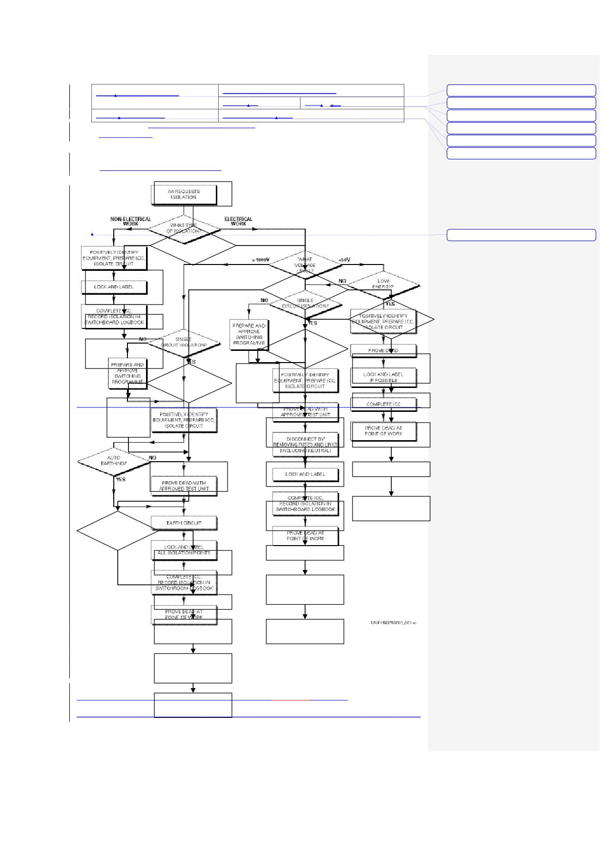
Flow Sheet Electrical Isolations
The controlled version of this document can be found at: http://baku.bpweb.bp.com/dep/hse/safe/
Next Revision Date: 01/12/2005
Print Date: 24/07/201015/11/2004
PAPER COPIES ARE UNCONTROLLED. THIS COPY VALID ONLY AT THE TIME OF PRINTING
Created on 04/02/2004 14:05
Page 15 of 23
Title: Energy Isolation -
Doc No: UNIF-HSE-PRO-106-C2
Formatted
Electrical
Rev No: C2
Page 27 of 45
Formatted
Dated: August, 2004
Originating Dept: HSE
Formatted
CASPIAN REGION: Electrical Isolation Standard
Formatted
UNIF-HSE-PRC-001
Formatted
Formatted
Flowsheet Electrical Isolations
AA REQUESTS
ISOLATION
ELECTRICAL/ INSTRUMENT
NON-ELECTRICAL WORK
WORK
Formatted
WHAT TYPE
OF ISOLATION?
POSITEVELY IDENTIFY
EQUIPMENT, PREPARE
>1000V
<50V
WHAT VOLTAGE
ICC, ISOLATE CIRCUIT
LEVEL?
NO
LOW ENERGY?
>50 & <1000
LOCK AND LABEL
COMPLETE ICC,
NO
SINGLE
YES
CIRCUIT
RECORD ISOLATION IN
ISOLATION?
SWITCHROOM LOGBOOK
POSITEVELY IDENTIFY
EQUIPMENT, PREPARE
PREPARE
ICC, ISOLATE CIRCUIT
AND
YES
NO
SINGLE
CIRCUIT
APPROVE
ISOLATION?
SWITCHING
PROGRAMME
PROVE DEAD
PREPARE
AND
APPROVE
SWITCHING
POSITEVELY IDENTIFY
PROGRAMME
EQUIPMENT, PREPARE
LOCK AND LABEL
ICC, ISOLATE CIRCUIT
IF POSSIBLE
POSITEVELY IDENTIFY
PROVE DEAD WITH
COMPLETE ICC
EQUIPMENT, PREPARE
APPROVED TEST UNIT
ICC, ISOLATE CIRCUIT
PROVE DEAD AT
DISCONNECT BY
POINT OF WORK
REMOVING FUSES AND
LINKS (INCL. NEUTRAL)
AUTO
NO
EARTH?
LOCK AND LABEL
PROVE DEAD WITH
YES
APPROVED TEST UNIT
COMPLETE ICC,
RECORD ISOLATION IN
SWITCHROOM LOGBOOK
EARTH CIRCUIT
LOCK AND LABEL
PROVE DEAD AT
ALL ISOLAION POINTS
POINT OF WORK
COMPLETE ICC,
RECORD ISOLATION IN
SWITCHROOM LOGBOOK
The controlled version of this document can be found at: http://baku.bpweb.bp.com/dep/hse/safe/
Next Revision Date: 01/12/2005
PROVE DEAD AT
Print Date: 24/07/201015/11/2004
PAPER COPIES ARE UNCONTPOINT OF WORKHIS COPY VALID ONLY AT THE TIME OF PRINTING
Created on 04/02/2004 14:05
Page 15 of 23
Title: Energy Isolation -
Doc No: UNIF-HSE-PRO-106-C2
Formatted
Electrical
Rev No: C2
Page 28 of 45
Formatted
Dated: August, 2004
Originating Dept: HSE
Formatted
CASPIAN REGION: Electrical Isolation Standard
Formatted
UNIF-HSE-PRC-001
Formatted
Formatted
The controlled version of this document can be found at: http://baku.bpweb.bp.com/dep/hse/safe/
Next Revision Date: 01/12/2005
Print Date: 24/07/201015/11/2004
PAPER COPIES ARE UNCONTROLLED. THIS COPY VALID ONLY AT THE TIME OF PRINTING
Created on 04/02/2004 14:05
Page 15 of 23
Title: Energy Isolation -
Doc No: UNIF-HSE-PRO-106-C2
Formatted
Electrical
Rev No: C2
Page 29 of 45
Formatted
Dated: August, 2004
Originating Dept: HSE
Formatted
CASPIAN REGION: Electrical Isolation Standard
Formatted
UNIF-HSE-PRC-001
Formatted
Formatted
Appendix A: Abbreviations and Definitions
11Abbreviations and Definitions
Formatted
Formatted: Bullets and Numbering
AA
Area Authority
AEP
Authorized Electrical Person
AIP
Authorized Instrument Person
BUL
Business Unit Leader
CI
Competent isolator
CMAS
Competence Management Assurance System
D
Main conductor disconnected
E
Earth the isolated conductor
IA
Isolating Authority
ICC
Isolation Control Certificate
Is
Isolate
IP
Ingress protection
SSOW
Safe System Of Work
LL
Lock and Label
LTI
Long-term isolations
P
Prove dead with proprietary voltage tester
PA
Performing Authority
REP
Responsible Electrical Person
SAEP
Senior Authorized Electrical Person
SP
Authorized Switching Programme
TA
Technical Authority
PTWW
Permit to Work
OIM
Offshore Installation Manager
OIM
Offshore Installation Manager
HV
“High Voltage” voltages that exceed 1000Vac or
1500Vdc between conductors or
600Vac or
900Vdc between conductors and earth
LV
“Low Voltage” is a voltage normally exceeding
extra low voltage by not exceeding 1000V ac or
1500 Vdc between conductors or
600Vac or
900Vdc between conductors and earth
ELV
“extra low voltage” Voltage which does not
exceed
50V ac rms between conductors or
between any conductor and earth, in a circuit
isolated from the supply be means such as a
safety isolating transformer or convertorconverter
with separate windings.
A voltage which does not exceed
50V dc
between conductors or any conductor and earth
in a circuit isolated from Higher voltage circuits
12References
Formatted: Bullets and Numbering
Hold
Authorization procedure
Hold
Electrical Safety Rules
BP CDZZZZ PM PRO 0002
Risk Assessments (Level 2 risk assessment)
UNIF -HSE-PRO-105
Work Site Risk Assessment
BP Golden Rules
Energy Isolation
The controlled version of this document can be found at: http://baku.bpweb.bp.com/dep/hse/safe/
Next Revision Date: 01/12/2005
Print Date: 24/07/201015/11/2004
PAPER COPIES ARE UNCONTROLLED. THIS COPY VALID ONLY AT THE TIME OF PRINTING
Created on 04/02/2004 14:05
Page 15 of 23
Title: Energy Isolation -
Doc No: UNIF-HSE-PRO-106-C2
Formatted
Electrical
Rev No: C2
Page 30 of 45
Formatted
Dated: August, 2004
Originating Dept: HSE
Formatted
CASPIAN REGION: Electrical Isolation Standard
Formatted
UNIF-HSE-PRC-001
Formatted
Formatted
The controlled version of this document can be found at: http://baku.bpweb.bp.com/dep/hse/safe/
Next Revision Date: 01/12/2005
Print Date: 24/07/201015/11/2004
PAPER COPIES ARE UNCONTROLLED. THIS COPY VALID ONLY AT THE TIME OF PRINTING
Created on 04/02/2004 14:05
Page 15 of 23
Title: Energy Isolation -
Doc No: UNIF-HSE-PRO-106-C2
Formatted
Electrical
Rev No: C2
Page 31 of 45
Formatted
Dated: August, 2004
Originating Dept: HSE
Formatted
CASPIAN REGION: Electrical Isolation Standard
Formatted
UNIF-HSE-PRC-001
Formatted
Formatted
13Appendix B: Applicable to ces
Formatted: Bullets and Numbering
13.1Appendix A - Applicable to
Formatted
This document applies to the following job functions:
Formatted: Bullets and Numbering
Area Authority
Authorized Electrical Personnel
Authorized Instrument Personnel
Business Unit Leader
Document Controller
Electrical Technical Authority
Isolating Authority
OIM / Site Manager / Site Controller
Operations Engineer
Performing Authority
Responsible Electrical Person
Senior Authorized Electrical Personnel
The controlled version of this document can be found at: http://baku.bpweb.bp.com/dep/hse/safe/
Next Revision Date: 01/12/2005
Print Date: 24/07/201015/11/2004
PAPER COPIES ARE UNCONTROLLED. THIS COPY VALID ONLY AT THE TIME OF PRINTING
Created on 04/02/2004 14:05
Page 15 of 23
Title: Energy Isolation -
Doc No: UNIF-HSE-PRO-106-C2
Formatted
Electrical
Rev No: C2
Page 32 of 45
Formatted
Dated: August, 2004
Originating Dept: HSE
Formatted
CASPIAN REGION: Electrical Isolation Standard
Formatted
UNIF-HSE-PRC-001
Formatted
Formatted
Appendix C
13.2: Appendix B - Adjacent Working Assessment
Formatted
Formatted: Bullets and Numbering
ADJACENT WORKING ASSESSMENT
(working adjacent to live conductors)
Sketch of Working Area
Is working position marked on sketch?
YES
NO
Is the working area clear and free of debris?
YES
NO
Are live adjacent voltages marked on sketch?
YES
NO
Is shrouding IP rating marked on sketch?
YES
NO
Size of smallest loose conductive component to be worked with?
mm
Is the IP rating below the working area adequate to prevent any loose
YES
NO
components being worked with falling on to live components?
Is the min IP protection IP2X or more?
YES
NO
Position:
Date:
Name:
Signature:
The controlled version of this document can be found at: http://baku.bpweb.bp.com/dep/hse/safe/
Next Revision Date: 01/12/2005
Print Date: 24/07/201015/11/2004
PAPER COPIES ARE UNCONTROLLED. THIS COPY VALID ONLY AT THE TIME OF PRINTING
Created on 04/02/2004 14:05
Page 15 of 23
Title: Energy Isolation -
Doc No: UNIF-HSE-PRO-106-C2
Formatted
Electrical
Rev No: C2
Page 33 of 45
Formatted
Dated: August, 2004
Originating Dept: HSE
Formatted
CASPIAN REGION: Electrical Isolation Standard
Formatted
UNIF-HSE-PRC-001
Formatted
Formatted
If any of the above are answered with “NO”, then please review work with REP
IP Classification list overleaf
The controlled version of this document can be found at: http://baku.bpweb.bp.com/dep/hse/safe/
Next Revision Date: 01/12/2005
Print Date: 24/07/201015/11/2004
PAPER COPIES ARE UNCONTROLLED. THIS COPY VALID ONLY AT THE TIME OF PRINTING
Created on 04/02/2004 14:05
Page 15 of 23
Title: Energy Isolation -
Doc No: UNIF-HSE-PRO-106-C2
Formatted
Electrical
Rev No: C2
Page 34 of 45
Formatted
Dated: August, 2004
Originating Dept: HSE
Formatted
CASPIAN REGION: Electrical Isolation Standard
Formatted
UNIF-HSE-PRC-001
Formatted
Formatted
ADJACENT WORKING ASSESSMENT
(working adjacent to live conductors)
IP - INGRESS PROTECTION
The IP classification system designates, by means of a number, the degree of
protection provided by an enclosure against impact or dust and water ingress.
Please note that the IP classification should not be construed as indicating corrosion
resistance.
Degrees of Protection to IEC 529
IP Classification list
IP0X
Non-protected.
IP1X
Protected against a solid object greater than 50mm, such as a hand.
IP2X
Protected against a solid object greater than 12mm, such as a finger.
IP3X
Protected against a solid object greater than 2.5mm, such as a tool or wire.
IP4X
Protected against a solid object greater than 1.0mm, such as wire or
thin strips.
IP5X
Dust-protected. Prevents ingress of dust sufficient to cause harm.
IP6X
Dust tight. No dust ingress.
The controlled version of this document can be found at: http://baku.bpweb.bp.com/dep/hse/safe/
Next Revision Date: 01/12/2005
Print Date: 24/07/201015/11/2004
PAPER COPIES ARE UNCONTROLLED. THIS COPY VALID ONLY AT THE TIME OF PRINTING
Created on 04/02/2004 14:05
Page 15 of 23
Title: Energy Isolation -
Doc No: UNIF-HSE-PRO-106-C2
Formatted
Electrical
Rev No: C2
Page 35 of 45
Formatted
Dated: August, 2004
Originating Dept: HSE
Formatted
CASPIAN REGION: Electrical Isolation Standard
Formatted
UNIF-HSE-PRC-001
Formatted
Formatted
The controlled version of this document can be found at: http://baku.bpweb.bp.com/dep/hse/safe/
Next Revision Date: 01/12/2005
Print Date: 24/07/201015/11/2004
PAPER COPIES ARE UNCONTROLLED. THIS COPY VALID ONLY AT THE TIME OF PRINTING
Created on 04/02/2004 14:05
Page 15 of 23
Title:
Doc No: UNIF-HSE-PRO-106-C2
Energy Isolation - Electrical
Rev No: C2
Page 36 of 45
Dated: June, 2004
Originating Dept: HSE
Appendix DC - Switching Programme:
Switching Programme
Formatted
Site:
ICC number
WCC number
Reason for switching:
Ref Drw no:
Electrical Key Single Line Diagram
Date:
The controlled version of this document can be found at: http://baku.bpweb.bp.com/dep/hse/safe/
Next Revision Date: 01/12/2005
Print Date: 24/07/201015/11/2004
PAPER COPIES ARE UNCONTROLLED. THIS COPY VALID ONLY AT THE TIME OF PRINTING
Title: Energy Isolation -
Doc No: UNIF-HSE-PRO-106-C2
Formatted
Electrical
Rev No: C2
Page 37 of 45
Formatted
Dated: August, 2004
Originating Dept: HSE
Formatted
CASPIAN REGION: Electrical Isolation Standard
Formatted
UNIF-HSE-PRC-001
Formatted
Formatted
Prepared by
Date:
Checked by
Date:
Site:
ICC
number
WCC number
Reason for switching:
Ref Drw no:
Electrical Key Single Line Diagram
Date of switching:
Item
Voltage
Switchboard
Cub/ Cir
Action
Comments
Key No
By
Ref.
The controlled version of this document can be found at: http://baku.bpweb.bp.com/dep/hse/safe/
Next Revision Date: 01/12/2005
Print Date: 24/07/201015/11/2004
PAPER COPIES ARE UNCONTROLLED. THIS COPY VALID ONLY AT THE TIME OF PRINTING
Created on 04/02/2004 14:05
Page 15 of 23
Title: Energy Isolation -
Doc No: UNIF-HSE-PRO-106-C2
Formatted
Electrical
Rev No: C2
Page 38 of 45
Formatted
Dated: August, 2004
Originating Dept: HSE
Formatted
CASPIAN REGION: Electrical Isolation Standard
Formatted
UNIF-HSE-PRC-001
Formatted
Formatted
Item
Voltage
Switchboard
Cub/ Cir
Action
Comments
Key No
By
Ref.
Prepared by
Date:
Checked by
Date:
The controlled version of this document can be found at: http://baku.bpweb.bp.com/dep/hse/safe/
Next Revision Date: 01/12/2005
Print Date: 24/07/201015/11/2004
PAPER COPIES ARE UNCONTROLLED. THIS COPY VALID ONLY AT THE TIME OF PRINTING
Created on 04/02/2004 14:05
Page 15 of 23
Title: Energy Isolation -
Doc No: UNIF-HSE-PRO-106-C2
Formatted
Electrical
Rev No: C2
Page 39 of 45
Formatted
Dated: August, 2004
Originating Dept: HSE
Formatted
CASPIAN REGION: Electrical Isolation Standard
Formatted
UNIF-HSE-PRC-001
Formatted
Formatted
The controlled version of this document can be found at: http://baku.bpweb.bp.com/dep/hse/safe/
Next Revision Date: 01/12/2005
Print Date: 24/07/201015/11/2004
PAPER COPIES ARE UNCONTROLLED. THIS COPY VALID ONLY AT THE TIME OF PRINTING
Created on 04/02/2004 14:05
Page 15 of 23
Title:
Doc No: UNIF-HSE-PRO-106-C2
Energy Isolation - Electrical
Rev No: C2
Page 40 of 45
Dated: June, 2004
Originating Dept: HSE
Appendix E: DOperational Locking System
Formatted
Locking system for electrical equipment after energisation covering operations
and isolation control
Operational locks
Each switchboard will have a locking suite of unique locks for each locking point on
the switchgear these will be housed in a lock cabinet within the switch room. Access
to the locking suite will be controlled to suitably authorized persons.
The locks should be a high security type which are tamper proof. ( an example of such a
lock is the ABLOY high security padlocks). There should only be one key that fits a lock
in the isolation system (any spares or masters are to be removed and controlled by the
site manager who should only issue these keys after the REP has made a formal request
in writing)
AUTHORIZED ACCESS
ACCESS
AIP
AEP
SAEP
HV switchboard locking suite
NO
NO
YES
SINGLE CIRCUITS
LV switchboard locking suite
NO
YES
YES
SINGLE CIRCUITS
Control locks
YES
YES
YES
Operational Locking
Formatted
Operational locks will normally be applied to:
Local remote switches
Formatted: Bullets and Numbering
Manual close switches on circuit breakers
Formatted: Bullets and Numbering
Earth switches
Formatted: Bullets and Numbering
Racking mechanisms
Formatted: Bullets and Numbering
The keys to these locks will be kept with the locking suite for the switchboard.
Isolation Locking
When the Area Authority requires an isolation to be locked off, a lock and key will be
taken from the switchboard-locking suite that the isolation is required for. Where
possible a multi-hasp will be used and the lock and label will be applied.
Once the locks are in place the keys will be returned with the ICC to the Area
Authority who will control the keys until a de-isolation or a sanction to test has been
approved.
The controlled version of this document can be found at: http://baku.bpweb.bp.com/dep/hse/safe/
Next Revision Date: 01/12/2005
Print Date: 24/07/201015/11/2004
PAPER COPIES ARE UNCONTROLLED. THIS COPY VALID ONLY AT THE TIME OF PRINTING
Doc No: UNIF-HSE-PRO-106-C2
Title: Energy Isolation -
Electrical
Rev No: C2
Page 41 of 45
Dated: August, 2004
Originating Dept: HSE
Formatted
CASPIAN REGION: Electrical Isolation Standard
UNIF-HSE-PRC-001
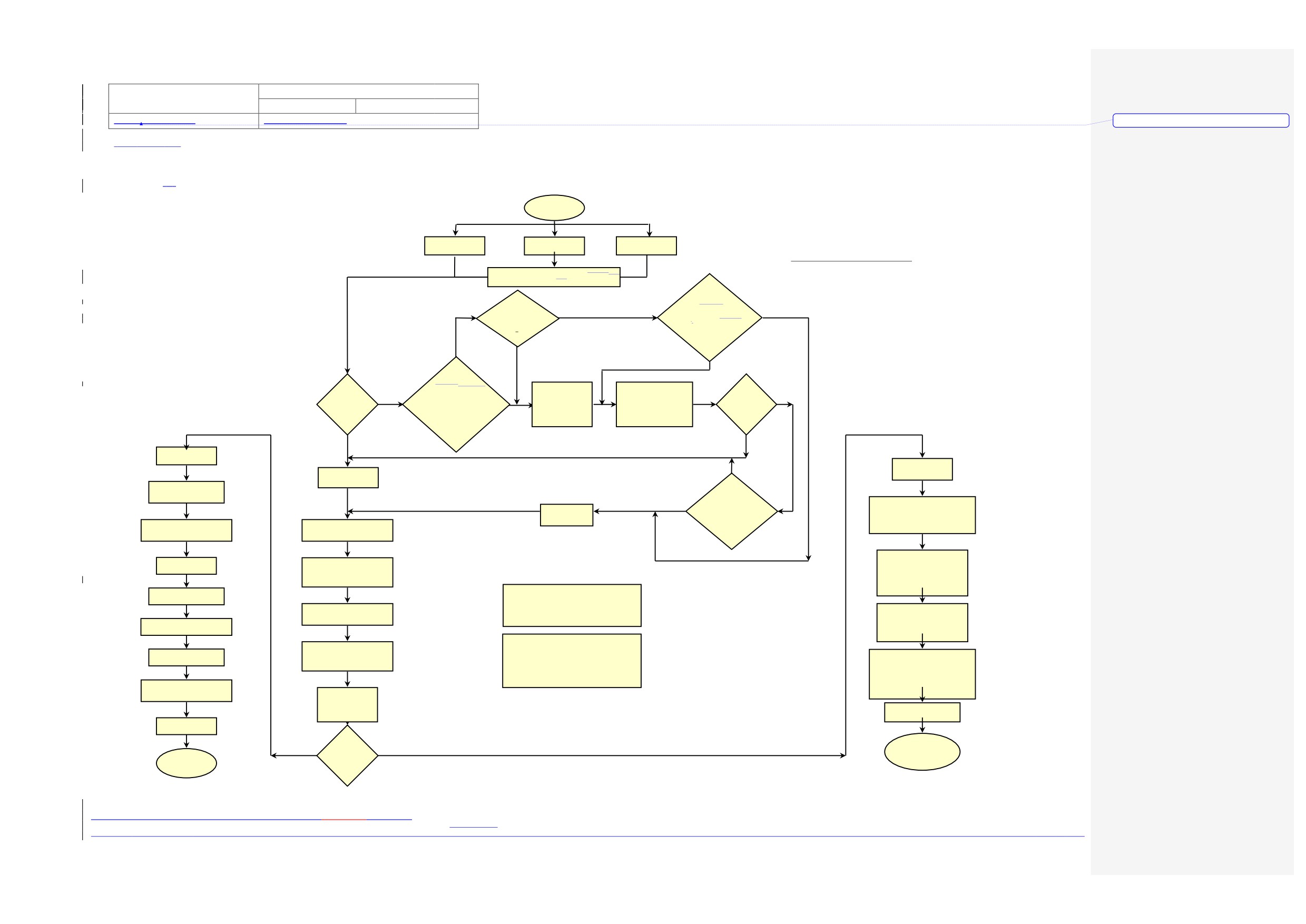
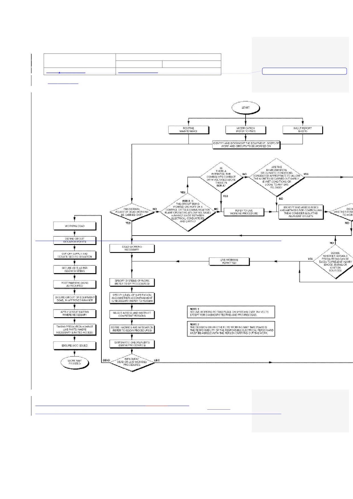
Appendix FE - : Control of Electrical Work
START
ROUT INE
MODIFICAT ION
FA ULT REPO RT
MA INTENANCE
REFER TO PMP
SHEETS
FILE NO. E96437.CHT
UPDATED 07/11/00
IDENT IFY AND DOCUMENT THE EQUIPMENT, SCOPE O F WO RK ANDWORK
AND CIRCUITS TO BETO BE W ORKED ON
ARE THE
IS
ENVIRONMENTAL
THERE A
O R CLIMATICO R CLIMATIC CONDIT IONS
POTENT IAL FO R
NO
CO NSIDERED APPROPRIATE TO
YES
CO MMING INTO CONTACT
ALLOW THE WO RK TO BE
W ITH VOLTAGES
CA RRIED OUT SAFELYOUT SA FELY.
ABOVE THOSE
iI.e. W ET CONDIT IONS
IN BOX
O R LOCAL TO ANY
A
GAS RELEASE.
YES
YES
NO
BOX A
IS THE
CIRCUIT BEINGCIRCUIT BEING
CAN
WORKED ON, PART OF A
NO RMAL
CO NT ROL O R TELECOMMUNICAT ION
REFER TO
IDENT IFY AND ASSESS
DECIDE
POLICY OF
NO
PLANT OPERATING AT LOW
RISKS AND METHODS
W HETHER IT
YES
DEAD WORKING
LIV E WORKING
FO R CONT ROLLING THEM
IS REASONABLE
VOLTAGES (<50v
PRO CEDURE
CO NSIDER ISOLATING
TO WORK
BE CA RRIED
BETWEEN ELECTRICA L
NO
ADJACENT CIRCUITS
LIV E
OUT
CO NDUCTORS AND
EA RTH)
YES
NO
WORKING DEAD
WORKING LIVE
DEAD WORKING
NO
NECESSARY
DEFINE CIRCUIT
ISO LATION POINTS
DECIDE
W HETHER SUITABLE
YES
PRECAUTIONS CAN BE
ENSURE SUITABLE WO RKING
LIV E WORKING
TAKEN TO PREVENT INJURY
PRECAUTIONS ARE TAKEN
PERMITTED
(SHOCK, BURNS OR
AND THAT SUITABLE PROTECT IVE
IGNIT ION SOURCES)
EQUIPMENT IS USED
CUT O FF SUPPLY AND
SPECIFY SYSTEMS OF W ORK
REFER BP
ISO LATE SECURE ISOLATION
PRO CEDURES
ENSURE ADEQUATE WORKING
SECURE KEYS AS PER
SPACE ACCESS & LIGHT ING,
SSOW SYSTEMS
SPECIFY LEVEL OF SUPERV ISION
REST RICT ACCESS TO A REA
AND W HETHER ACCOMPANIMENT
O F LIVE WORK AND
NECESSARY
POST DANGER SIGNS.
REFER HS(HS (G) 85
POST WARNING SIGNS
NOTE 1
AS REQUIRED
NO LIVE WORKING TO TAKE PLACE ON
SYSTEMS OVER 750 VOLTS
SELECT ACCESSAND INSTRUCT
EXCEPT FOR DIAGNOSTIC TESTING AND PROVING DEAD
CO MPETENT PERSONS
TAKE PRECAUTION AGAINST
ADJACENT LIVE PA RTS
W HERE NECESSARY
ENSURE CIRCUIT O R EQUIPMENT
(LIMITED ACCESS)
DEAD. IN APPROVED MANNER
NOTE 2
THE DECISION ON W HETHER LIVE WORKING
DEFINE HAZARDS AND MITIGATION
MAY TAKE PLACE IS THE RESPONSIBILITY
APPLY CIRCUIT EA RTHS
(REFER SSOW PROCEDURES)
O F THE RESPONSIBLE ELECTRICA L PERSON, AND
ENSURE ACCOMPANIEMENT IS
W HERE NECESSARY
ENSURE USE O F SUITABLE
MUST BE AGREED W ITH THE PERSON CARRY ING
PROTECT IVE EQUIPMENT
PROVIDED. ACCOMPANIEMENT TO BE
OUT THE WORK.
SUITABLY TRAINED IN FIRST A ID
AND TO A TECHNICA L LEVEL
TAKING PRECAUTION
AGA INST LIVE PARTS W HERE
NECESSARY (LIMITED ACCESS)
SYSTEMATIC
CHECKS/ AUDITS
(SSOW PROCEDURES)
ENSURE W CC USED
ENSURE PTW
ISSUED
IMPLEMENT
WORK MAY
DEAD
DEAD OR
LIV E
PRO CEED
LIV E WORKING
W ITH CAUTION
WORK MAY
PRO CEDURES
PRO CEED
The controlled version of this document can be found at: http://baku.bpweb.bp.com/dep/hse/safe/
Next Revision Date: 01/12/2005
Print Date: 24/07/201015/11/2004
PAPER COPIES ARE UNCONTROLLED. THIS COPY VALID ONLY AT THE TIME OF PRINTINGWorking Draft
Created on 04/02/2004 14:05
Page 23 of 25
Title: Energy Isolation -
Doc No: UNIF-HSE-PRO-106-C2
Electrical
Rev No: C2
Page 42 of 45
Dated: August, 2004
Originating Dept: HSE
Formatted
CASPIAN REGION: Electrical Isolation Standard
UNIF-HSE-PRC-001
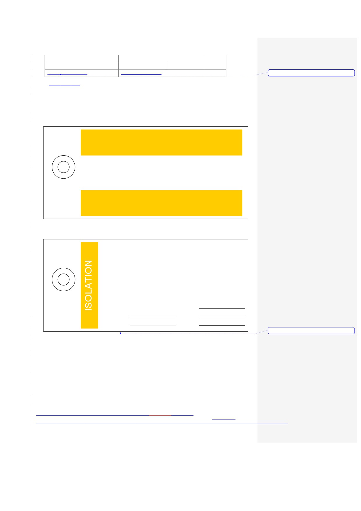
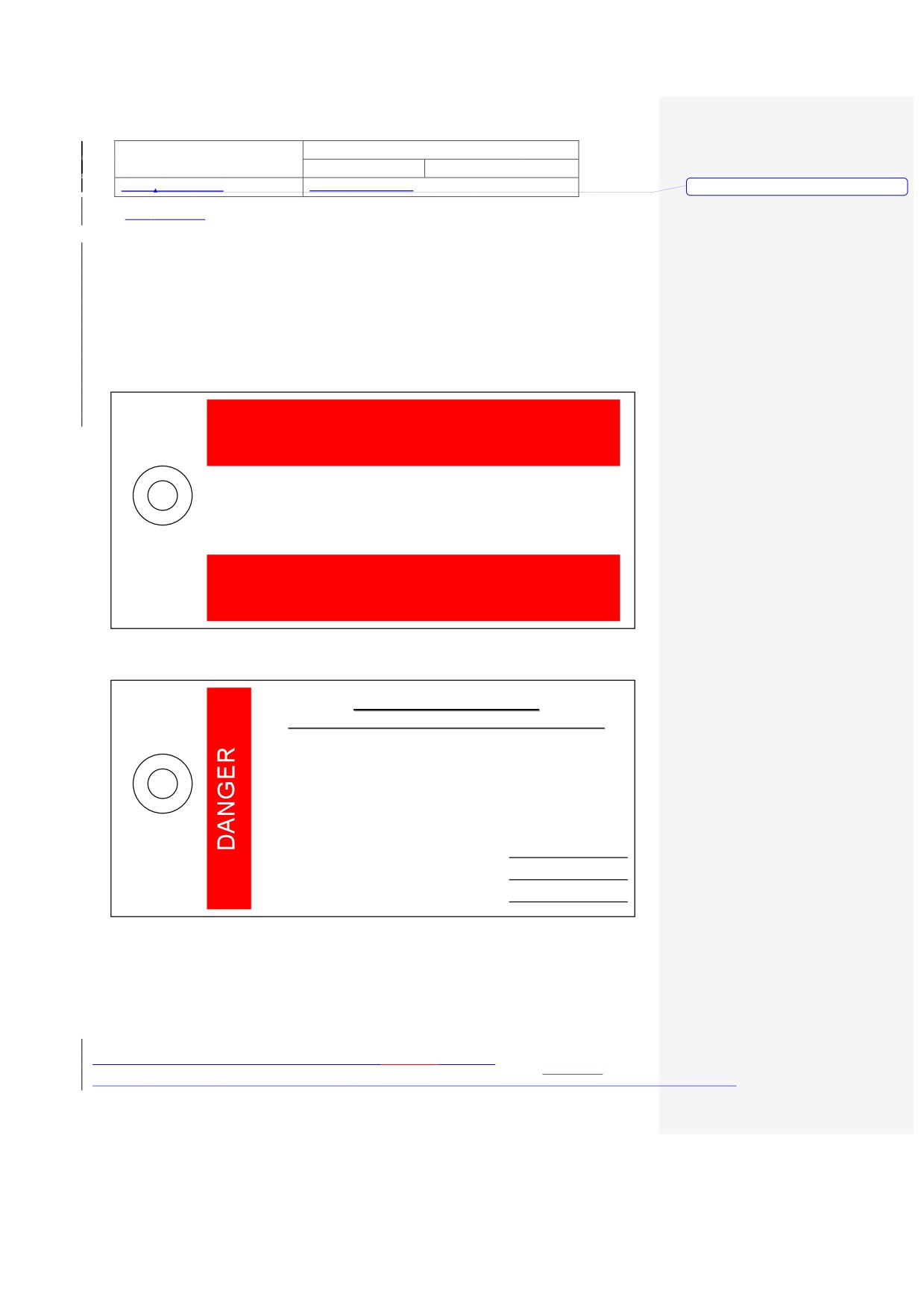
Appendix G: Labels
ISOLATION
NOTICE
REASON FOR ISOLATION :
ISOLATION
NAME
POINT
TAG No
SIGNED
ICC
DATE
o
Formatted
The controlled version of this document can be found at: http://baku.bpweb.bp.com/dep/hse/safe/
Next Revision Date: 01/12/2005
Print Date: 24/07/201015/11/2004
PAPER COPIES ARE UNCONTROLLED. THIS COPY VALID ONLY AT THE TIME OF PRINTINGWorking Draft
Created on 04/02/2004 14:05
Title: Energy Isolation -
Doc No: UNIF-HSE-PRO-106-C2
Electrical
Rev No: C2
Page 43 of 45
Dated: August, 2004
Originating Dept: HSE
Formatted
CASPIAN REGION: Electrical Isolation Standard
UNIF-HSE-PRC-001
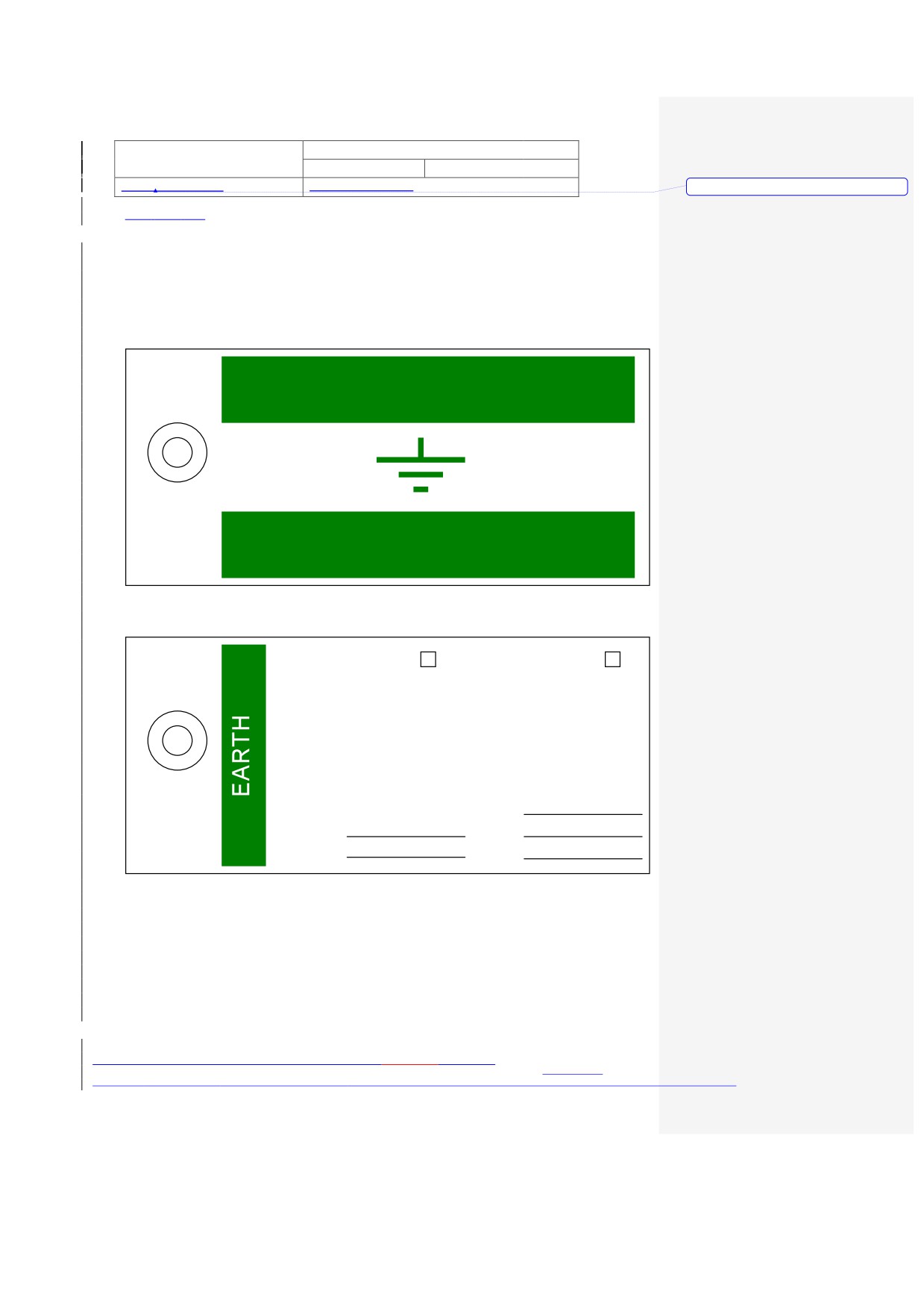
EARTH
NOTICE
CIRCUIT MAIN
ADDITIONAL
REASON FOR EARTH :
ISOLATION
NAME
POINT
TAG NO
SIGNED
ICC No
DATE
The controlled version of this document can be found at: http://baku.bpweb.bp.com/dep/hse/safe/
Next Revision Date: 01/12/2005
Print Date: 24/07/201015/11/2004
PAPER COPIES ARE UNCONTROLLED. THIS COPY VALID ONLY AT THE TIME OF PRINTINGWorking Draft
Created on 04/02/2004 14:05
Title: Energy Isolation -
Doc No: UNIF-HSE-PRO-106-C2
Electrical
Rev No: C2
Page 44 of 45
Dated: August, 2004
Originating Dept: HSE
Formatted
CASPIAN REGION: Electrical Isolation Standard
UNIF-HSE-PRC-001
DANGER
NOTICE
LIVE EQUIPMENT
DO NOT INTERFERE WITH THIS EQUIPMENT
REASON FOR DANGER NOTICE :
NAME
SIGNED
DATE
The controlled version of this document can be found at: http://baku.bpweb.bp.com/dep/hse/safe/
Next Revision Date: 01/12/2005
Print Date: 24/07/201015/11/2004
PAPER COPIES ARE UNCONTROLLED. THIS COPY VALID ONLY AT THE TIME OF PRINTINGWorking Draft
Created on 04/02/2004 14:05
Title: Energy Isolation -
Doc No: UNIF-HSE-PRO-106-C2
Electrical
Rev No: C2
Page 45 of 45
Dated: August, 2004
Originating Dept: HSE
Formatted
CASPIAN REGION: Electrical Isolation Standard
UNIF-HSE-PRC-001
The controlled version of this document can be found at: http://baku.bpweb.bp.com/dep/hse/safe/
Next Revision Date: 01/12/2005
Print Date: 24/07/201015/11/2004
PAPER COPIES ARE UNCONTROLLED. THIS COPY VALID ONLY AT THE TIME OF PRINTINGWorking Draft
Created on 04/02/2004 14:05
AZERBAIJAN BUSINESS UNIT
(AzBU)
Procedure for:
Energy Isolation - Process
Issued for
C2
09.09.04
G.Stacey
SSoW WG
N.McCleary
G. Campbell
use
Rev
Date
Reason for
Prepared by
Checked by
Approved by
Endorsed by
Issue
Notes: C2:Complete rewrite
HSE - SAFETY
taking into consideration SIRP
Azerbaijan BU Document Reference
requirements
Asset Code
Dept Code
Document Type
Sequence No
Revision Code
UNIF
HSE
PRO
107
C2
The controlled version of this document can be found at: http://baku.bpweb.bp.com/dep/hse/safe/
Next Revision Date: 30/09/2005
Print Date: 24/07/2010
PAPER COPIES ARE UNCONTROLLED. THIS COPY VALID ONLY AT THE TIME OF PRINTING
Title: Energy Isolation - Process
Doc No: UNIF-HSE-PRO-107-C2
Rev No: C2
Page 2 of 36
Dated: September, 2004
Originating Dept: HSE
TABLE OF CONTENTS
1
INTRODUCTION
4
1.1
PURPOSE
4
1.2
DEVIATIONS
4
1.3
SCOPE
4
1.4
DOCUMENT REVIEW
4
1.5
SSOW SPECIFIC CROSS REFERENCES
4
1.6
BP GOLDEN RULES
5
1.7
LANGUAGE FACILITATION
5
2
ROLES AND RESPONSIBILITIES
6
2.1
PERFORMANCE UNIT LEADER
6
2.2
ASSET MANAGER
6
2.3
OIM / SITE CONTROLLER (SC) / ONSHORE SITE MANAGER (OSM)
6
2.4
AREA AUTHORITY (AA)
6
2.5
ISOLATING AUTHORITY (IA)
7
2.6
PERFORMING AUTHORITY
7
2.7
MAINTENANCE PERSONNEL
7
2.8
THE ONSHORE SUPPORT ENGINEER
7
2.9
CUSTODIAN
7
3
MONITORING AND AUDITING OF ISOLATIONS
8
3.1
MONITORING
8
3.2
SELF-REGULATION AND AUDIT
8
4
COMPETENCY, TRAINING AND AWARENESS
9
4.1
GENERAL
9
4.2
LEVELS OF TRAINING
9
5
THE ISOLATION CONFIRMATION CERTIFICATION (ICC) PROCESS10
5.1
GENERAL
10
6
ISOLATION REVIEW AND LEVEL 2 RISK ASSESSMENT PROCESS11
6.1
REVIEW AND RISK ASSESSMENT PROCESS
11
6.2
REJECTION OF ISOLATION DESIGN
11
6.3
RISK ASSESSMENT OF NON-COMPLIANT ISOLATIONS
11
6.4
RISK ASSESSMENT RECORDS
12
6.5
HAZARDOUS WORK
12
7
TYPES OF ISOLATIONS
12
7.1
BOUNDARY ISOLATIONS
12
7.2
LONG-TERM ISOLATIONS
13
7.3
PERSONAL ISOLATIONS
13
7.4
ADDITIONAL ISOLATIONS
13
7.5
ISOLATION FOR CONFINED SPACE ENTRY
14
7.6
PROVISION FOR ISOLATIONS DURING MODIFICATION OF DESIGN AND NEW FACILITIES 14
8
REGISTERS
15
9
RECORDS
15
The controlled version of this document can be found at: http://baku.bpweb.bp.com/dep/hse/safe/
Next Revision Date: 30/09/2005
Print Date: 24/07/2010
PAPER COPIES ARE UNCONTROLLED. THIS COPY VALID ONLY AT THE TIME OF PRINTING
Title: Energy Isolation - Process
Doc No: UNIF-HSE-PRO-107-C2
Rev No: C2
Page 3 of 36
Dated: September, 2004
Originating Dept: HSE
APPENDIX A - DEFINITIONS & ABBREVIATIONS
16
APPENDIX B - ISOLATION STANDARDS
18
APPENDIX C - GUIDANCE NOTES
20
APPENDIX D - TYPICAL VALVE ISOLATIONS INTEGRITY TESTS
33
APPENDIX E - ENERGY ISOLATIONS FLOWCHART
36
The controlled version of this document can be found at: http://baku.bpweb.bp.com/dep/hse/safe/
Next Revision Date: 30/09/2005
Print Date: 24/07/2010
PAPER COPIES ARE UNCONTROLLED. THIS COPY VALID ONLY AT THE TIME OF PRINTING
Title: Energy Isolation - Process
Doc No: UNIF-HSE-PRO-107-C2
Rev No: C2
Page 4 of 36
Dated: September, 2004
Originating Dept: HSE
1
INTRODUCTION
1.1
PURPOSE
This purpose of this document is to ensure there is clarity to the detailed requirements that
applies to the preparation for isolationand reinstatement of process, utility and drilling systems.
A glossary of the terms used in the document is given in Appendix A.
1.2
DEVIATIONS
The procedures are written in sufficient detail that they should be able to be applied consistently
at all sites. There may still be the requirement for some local rules covering site-specific
logistical/administrative arrangements and local variations in responsibilities to reflect
differences in organisational arrangements. These local rules should not deviate from the core
processes within this document. Any form of deviation from this procedure, including but not
limited to local rules, shall be requested and authorised in accordance with the SSOW
Deviations from Regulations and Procedures procedure (Doc. No. UNIF-HSE-PRO-101)
1.3
SCOPE
The scope covers defined activities of BP and Contractors at all BP AzBU sites and installations.
1.4
DOCUMENT REVIEW
This document will be reviewed on an annual basis when users from the sites will have an
opportunity to propose changes to the existing processes and procedures. The document
Technical Authority will be responsible for coordinating this review.
1.5
SSOW SPECIFIC CROSS REFERENCES
This SSOW procedure shall, where appropriate, be used in conjunction with this suite of BP
AzBU SSOW Procedures referenced below.
Document Number
Title of Procedure
UNIF - HSE- PRO - 101
Deviations from Regulations and Procedures
UNIF - HSE- PRO - 102
Incident Investigation and Reporting
UNIF - HSE- PRO - 103
Permit To Work
UNIF - HSE- PRO - 104
Authorisation
UNIF - HSE- PRO - 105
Task Risk Assessment
UNIF - HSE- PRO - 106
Energy Isolations-Electrical
UNIF - HSE- PRO - 107
Energy Isolations-Process
UNIF - HSE- PRO - 108
Confined Space Entry
UNIF - HSE- PRO - 241
Leak Testing
The controlled version of this document can be found at: http://baku.bpweb.bp.com/dep/hse/safe/
Next Revision Date: 30/09/2005
Print Date: 24/07/2010
PAPER COPIES ARE UNCONTROLLED. THIS COPY VALID ONLY AT THE TIME OF PRINTING
Title: Energy Isolation - Process
Doc No: UNIF-HSE-PRO-107-C2
Rev No: C2
Page 5 of 36
Dated: September, 2004
Originating Dept: HSE
1.6
BP GOLDEN RULES
Energy Isolation is one of BP‟s Golden Rules. It states that:
“Any isolation of energy systems: mechanical, electrical, process, hydraulic and others, cannot
proceed unless:
The method of isolation and discharge of stored energy are agreed and executed by a
competent person(s)
Any Stored energy is discharged
A system of locks and tags is utilised at isolation points
A test is conducted to ensure the isolation is effective
Isolation effectiveness is periodically monitored”
1.7
LANGUAGE FACILITATION
Due to the various languages spoken at site, there is a necessity to assist all with “an ease of
understanding”. Therefore, the development and use of information tools are available.
The controlled version of this document can be found at: http://baku.bpweb.bp.com/dep/hse/safe/
Next Revision Date: 30/09/2005
Print Date: 24/07/2010
PAPER COPIES ARE UNCONTROLLED. THIS COPY VALID ONLY AT THE TIME OF PRINTING
Title: Energy Isolation - Process
Doc No: UNIF-HSE-PRO-107-C2
Rev No: C2
Page 6 of 36
Dated: September, 2004
Originating Dept: HSE
2
ROLES AND RESPONSIBILITIES
2.1
PERFORMANCE UNIT LEADER
The Performance Unit Leader is responsible for operating in accordance with this document and
for the self-regulation of compliance.
2.2
ASSET MANAGER
The Asset Managers are responsible for:
Ensuring that the Processes applied at their sites are authorised by them prior to
implementation
Periodic internal review
2.3
OFFSHORE INSTALLATION MANAGER (OIM) / SITE CONTROLLER (SC) / ONSHORE SITE
MANAGER (OSM)
The OIM/Site Controller/Site Manager is responsible for ensuring that those performing the roles
of Area Authority, Isolating Authority and Performing Authority are competent to do so and have
overall responsibility for the implementation of the Permit to Work and isolation procedures at
their site. They are responsible for:
Ensuring the operation and assurance of the isolation procedure at their site, acting
upon all recommendations and proposing system improvements
Authorising the Area Authority and Isolating Authority (in writing) as competent to
carry out their responsibilities within the Permit To Work and isolations procedures
Maintaining a control log of all authorised personnel. Details of this control log are
included in UNIF-HSE-PRO-104 Authorisation.
Communicating the responsibilities of key participants within the isolations procedures
to those personnel under their direction
Approving all Level 2 Risk Assessments undertaken for non-compliant isolations
Ensuring the required competent personnel are available at the installation to carry
out isolation activities.
Ensuring that plant and equipment isolations are subjected to the appropriate level of
self-regulation and audit.
2.4
AREA AUTHORITY (AA)
The Area Authority is responsible for approving the isolation design, providing assurance that
the design achieves the highest quality of isolation reasonably practicable. He/She can delegate
the detailed isolation design to an Isolating Authority. The Area Authority is then responsible for
authorising the work to proceed under the appropriate controls. They are responsible for:
Ensuring only authorized personnel perform isolations
Advising the OIM/Site Controller on Isolating Authority (IA) competence
Ensuring isolation specification, application, removal, certification and security are
The controlled version of this document can be found at: http://baku.bpweb.bp.com/dep/hse/safe/
Next Revision Date: 30/09/2005
Print Date: 24/07/2010
PAPER COPIES ARE UNCONTROLLED. THIS COPY VALID ONLY AT THE TIME OF PRINTING
Title: Energy Isolation - Process
Doc No: UNIF-HSE-PRO-107-C2
Rev No: C2
Page 7 of 36
Dated: September, 2004
Originating Dept: HSE
accomplished in accordance with this procedure
Facilitating the Risk Assessment process in accordance with UNIF-HSE-PRO-103 Task
Risk Assessment
Approving all Energy Isolations
The weekly review and quarterly audit of long-term isolations
The control of all lock-off devices and tags involved with isolations.
2.5
ISOLATING AUTHORITY (IA)
The Isolating Authority is responsible for:
The specification, application, removal and recording of Energy Isolations in support of a
Permit to Work
The design of process isolation when requested by the Area Authority. When designing
the isolation the Isolating Authority must agree the scope and content of isolation with
appropriate personnel e.g. the Performing Authority.
Isolating specific sections of plant or items of equipment to the highest quality and
security of isolation, which is reasonably practicable.
Demonstrating to the Performing Authority the integrity of the Energy Isolations
Monitoring of isolations in-place
2.6
PERFORMING AUTHORITY
The Performing Authority is the person charged with the responsibility of carrying out the work
and has the right to request demonstration of the integrity of any isolation. They are responsible
for checking that Energy Isolations `have been implemented in accordance with the isolation
specification before starting work.
2.7
MAINTENANCE PERSONNEL
Maintenance personnel work under the direction of the Isolating Authority and are responsible
for installing the means of isolation (e.g., spades) and removing equipment / pipe work (e.g.,
spool pieces) taking into consideration the equipment rating and service.
2.8
THE ONSHORE SUPPORT ENGINEER
The Onshore Support Engineer is responsible for providing engineering advice and guidance to
the Area Authority.
2.9
CUSTODIAN
The custodian of this document is the Technical Authority for Energy Isolations Process. The TA
is responsible for ensuring that an annual review of this document is carried out.
The controlled version of this document can be found at: http://baku.bpweb.bp.com/dep/hse/safe/
Next Revision Date: 30/09/2005
Print Date: 24/07/2010
PAPER COPIES ARE UNCONTROLLED. THIS COPY VALID ONLY AT THE TIME OF PRINTING
Title: Energy Isolation - Process
Doc No: UNIF-HSE-PRO-107-C2
Rev No: C2
Page 8 of 36
Dated: September, 2004
Originating Dept: HSE
3
MONITORING AND AUDITING OF ISOLATIONS
3.1
MONITORING
The integrity of each isolation point shall be monitored at suitable intervals to detect any actual
leakage or deterioration in condition caused, for example, by vibration or disturbance
(or
changing pressure upstream). This monitoring may involve partial testing of valve isolations as
suggested in Appendix D. The minimum recommended frequency of monitoring is once per shift
and immediately prior to breaking containment. The results of any monitoring of isolation
integrity shall be recorded and will form part of the shift handover.
3.2
SELF-REGULATION AND AUDIT
Each Business Asset shall:
Undertake internal audits of the operation of Energy Isolations at each site.
Maintain an Audit Register.
Have in place a system for tracking recommendations through to closeout.
Periodically review isolation-related activities including review of individual isolations and
the overall isolation process. Such reviews may also include.
o General compliance with this document and any local procedures
o The Level 2 Risk Assessment of non-compliant isolation and the extent of any
approved deviations
o A register of competent Isolating Authorities.
The use of a standard audit checklist is recommended, to allow comparison with externals audit
results. Audits, which are independent of the location, shall be carried out and will form part of
the Site Safety Adviser‟s audit programme and the HSE compliance assurance programme.
The recommended frequency of audit is as follows:
Installation /Site personnel
1 permit and isolation confirmation (ICC) certificate per day
Site Safety Adviser
1 permit and isolation confirmation (ICC) certificate per week
Site Manager/Controller
1 permit and isolation confirmation (ICC) certificate per month
Note: Audits should be a cross section of activities ongoing i.e. hot work, cold work, and spark
potential. Installation / Site personnel should carry out audits of individual tasks covering both
the PTW and the Isolation Confirmation Certificate (ICC) on a regular basis.
Site Managers shall carry out regular internal reviews of the findings of Energy Isolation
Certificates, to ensure that any critical failings in the system, or its manner of implementation,
have been identified and appropriate actions have been or will be taken.
The BU HSE Department as part of their audit schedule shall carry out Energy Isolation audits.
Such audits shall examine a cross section of at least 20 Energised Isolations together with
compliance to this procedure and any deviations in place.
The results of the audit shall be discussed with Management and issued for information and
action as appropriate.
The controlled version of this document can be found at: http://baku.bpweb.bp.com/dep/hse/safe/
Next Revision Date: 30/09/2005
Print Date: 24/07/2010
PAPER COPIES ARE UNCONTROLLED. THIS COPY VALID ONLY AT THE TIME OF PRINTING
Title: Energy Isolation - Process
Doc No: UNIF-HSE-PRO-107-C2
Rev No: C2
Page 9 of 36
Dated: September, 2004
Originating Dept: HSE
4 COMPETENCY, TRAINING AND AWARENESS
4.1
GENERAL
All personnel involved in Energy Isolations-Process shall be trained and deemed competent.
The competency of all relevant personnel shall be determined during the planning process for
any particular risk assessment. The Area Authority and/or Line Supervisor shall ensure that the
personnel involved in the activity have the correct competencies by examining records, or
requesting individuals to produce relevant certification.
4.2
LEVELS OF TRAINING
A training programme providing initial and refresher training and trainee assessment on the
contents of this document shall be carried out involving all personnel responsible for the
specification, approval, application and recording of process isolations.
The competency requirements for energy isolations - process for the key positions within this
document are as follows:
Area Authority, OIM/Site Controller/Onshore Site Manager, Department Heads
Theory in Energy Isolations-Process :1 day classroom, followed
Initial training
by 1 day Workplace Assessment Practical.
Practical or CBT (2 yearly), or if away from site/installation for
Refresher training
more than 12 months
Isolating Authorities
Practical in Energy Isolations-Process - 1 day classroom, 1 day
Initial training
Workplace Assessment
Practical Workplace Assessment: Before being deemed
competent to carry out process isolating duties, the Isolating
Authority must have been assessed at the workplace by a
competent Assessor. The Isolating Authority shall demonstrate
by practical example that he is competent ito design and
implement process isolations. The process for carrying out
workplace assessments is described in the workplace
Assessment Plan (see Appendix F)
Practical or CBT (2 yearly), or if away from site/installation for
Refresher training
more than 12 months
In special circumstances such as drilling operations, individuals can be assessed as competent
isolators for specific items of equipment providing that they have completed the formal training
and have been assessed as competent on the specific tasks. Site management is responsible
for ensuring that this is recorded so that it is clear which tasks these individuals are competent
to undertake.
The controlled version of this document can be found at: http://baku.bpweb.bp.com/dep/hse/safe/
Next Revision Date: 30/09/2005
Print Date: 24/07/2010
PAPER COPIES ARE UNCONTROLLED. THIS COPY VALID ONLY AT THE TIME OF PRINTING
Title: Energy Isolation - Process
Doc No: UNIF-HSE-PRO-107-C2
Rev No: C2
Page 10 of 36
Dated: September, 2004
Originating Dept: HSE
5
THE ISOLATION CONFIRMATION CERTIFICATION (ICC) PROCESS
5.1
GENERAL
Where isolations are required an Isolation Confirmation Certificate (ICC) must be completed as
detailed in the Permit To Work (PTW) procedure.
The Isolation Confirmation Certificate supports the Permit to Work by providing the means of:
Recording the isolations which are required before the task detailed on the associated
Permit to Work can proceed
Confirming that the isolations have been made for the task to proceed (subject to
authorisation of other certificates e.g., Confined Space Entry)
Authorisation and recording of de-isolations and isolations which may be required to
test equipment under a Sanction To Test (STT)
Authorisation and recording of de-isolation on completion of the task detailed on the
associated Permit to Work.
Note: The Isolation Confirmation Certificate (ICC) must be completed before the relevant
Permit to Work can be issued
The Area Authority, IA and Authorised Electrical Persons involved must be fully informed of the
plant, equipment or system to be worked upon and the scope of work to be carried out under
each permit where isolations are required. Marked-up Process & Instrument Diagrams and site
checks must be utilised to ensure that the plant, equipment or system is clearly identified for
isolation.
When each isolation is complete, the Isolating Authority/Authorised Electrical Person enters the
isolation details onto the Isolation Confirmation Certificate. The certificate must be cross-
referenced to the initial permit and any subsequent permits that utilise the same isolations.
Note: The Isolation Confirmation Certificate is raised before the permit is issued, and remains
in force (as a minimum) until the permit is cancelled.
The Isolation Certificate shall only be cancelled when “WORK is COMPLETE”. The Area
Authority can then sign the “CANCELLATION” section.
A single individual may not define and approve the design of energy isolations. The
Isolating Authorities are responsible for designing the isolation but must liase with the
Area Authority, Support Engineer (where applicable) and Performing Authority on the
scope, content and application method of proposed isolations.
The controlled version of this document can be found at: http://baku.bpweb.bp.com/dep/hse/safe/
Next Revision Date: 30/09/2005
Print Date: 24/07/2010
PAPER COPIES ARE UNCONTROLLED. THIS COPY VALID ONLY AT THE TIME OF PRINTING
Title: Energy Isolation - Process
Doc No: UNIF-HSE-PRO-107-C2
Rev No: C2
Page 11 of 36
Dated: September, 2004
Originating Dept: HSE
6
ISOLATION REVIEW AND LEVEL 2 RISK ASSESSMENT PROCESS
6.1
REVIEW AND RISK ASSESSMENT PROCESS
Where an isolation cannot achieve the standard detailed in Energy Isolations Process the Area
Authority or Support Engineer is responsible for commencing the Isolation Review and Risk
Assessment:
As a minimum, the Area Authority or Support Engineer together with the Isolating Authority, and
the Performing Authority complete a Risk Assessment. There must be three members minimum
for a Level 2 Risk Assessment.
The completed Risk Assessment shall be submitted to the OIM/Site Controller/Site Manager
who will, if necessary, discuss and clarify the isolation design with the team. If accepted, the
OIM/Site Controller/Site Manager shall approve the Risk Assessment.
When a satisfactory method of achieving isolation is agreed, isolations are planned, carried out
and documented in accordance with the methodology described in the Permit To Work
procedure, Energy Isolations Process procedure and the Task Risk Assessment procedure.
6.2
REJECTION OF ISOLATION DESIGN
Under no circumstances where the Isolation Review procedure is used, shall any proposed
isolation design be carried out without the agreement of the team involved in the Risk
Assessment.
Where the proposed isolation design is reviewed by the OIM/Site Controller/Site Manager and
rejected, new proposals in accordance with the Process Isolation Selection Chart shall be
proposed, or a new Risk Assessment Record sheet submitted.
Note: No amendments or additions to the Risk Assessment Record sheet shall be made.
6.3
RISK ASSESSMENT OF NON-COMPLIANT ISOLATIONS
In the event that the minimum recommended isolation standard cannot be achieved, a Level 2
Risk Assessment shall be carried out according to the following guidelines:
The assessment team shall specify appropriate safeguards, which may replace or be in
addition to those listed in Table 1 (Appendix B). The team shall be satisfied that these
safeguards shall reduce the risks to an acceptable level before the Level 2 Risk
Assessment is submitted to the OIM/SC/SM for the task requiring isolation is permitted to
proceed
When risk assessing non-compliant isolations, consideration shall be given to the risks
associated with swinging large spades compared with the risk associated with the lower
level of isolation
Consideration shall be given to: extended monitoring periods, prior to breaking
containment, reducing the duration of the tasks, provision of a permanent standby man,
development of a contingency plan for isolation failure.
The controlled version of this document can be found at: http://baku.bpweb.bp.com/dep/hse/safe/
Next Revision Date: 30/09/2005
Print Date: 24/07/2010
PAPER COPIES ARE UNCONTROLLED. THIS COPY VALID ONLY AT THE TIME OF PRINTING
Title: Energy Isolation - Process
Doc No: UNIF-HSE-PRO-107-C2
Rev No: C2
Page 12 of 36
Dated: September, 2004
Originating Dept: HSE
Full consideration shall be given to the alternatives including partial or full production
shutdown or deferral of the work
The recommendations from the Level 2 Risk Assessment shall be approved by the
OIM/Site Controller who may also recommend further review by technical specialists or
management before taking the decision on whether to proceed with the work
6.4
RISK ASSESSMENT RECORDS
The Risk Assessment shall be attached to the appropriate Permit(s).
6.5
HAZARDOUS WORK
Where hazardous or potentially hazardous work such as spading, removing a section of
pipeline, or electrical disconnection is required, a permit must be raised to carry out the isolation.
7
TYPES OF ISOLATIONS
There are varying types of isolations, which are described within this section. These include:
Boundary Isolations
Long Term Isolation
Personal Isolations
Additional Isolations
Isolation for Confined Space Entry
7.1
BOUNDARY ISOLATIONS
Where an area of plant is isolated such that several activities can safely take place within this
common set of strategically placed isolation points then this can be termed as a 'Boundary
Isolation'. It must be clearly identified that the isolation is appropriate for all the individual tasks to
be carried out against the Boundary Isolation. An Isolation Certificate is raised and identified, as
Boundary Isolation and all individual PTW are cross-referenced to this Boundary Isolation.
If any of the proposed tasks requires a level of isolation or implementation of control measures
greater than that covered by the Boundary then a separate Isolation Certificate should be raised
for this task.
Once work is in progress and subsequent PTW is applied for within the recognised framework of
the Boundary Isolation, they can be added providing it is clearly established that the existing
isolation is appropriate for the task. However, this should be avoided if possible and it is
preferable to identify all activities when the Boundary Isolation is being planned.
Entry to a confined space within a boundary requires separate Isolation and a Confined Space
Entry Certificate to be raised.
No isolations within Boundary isolation shall be removed until all applicable PTW having been
cancelled.
If for any reason work on a particular piece of plant within the Boundary needs to be suspended
(e.g. whilst awaiting spares) then a separate isolation shall be implemented and an ICC raised
before the Boundary Isolation can be cancelled.
Where the de-isolation of boundary isolations is proposed, an isolation review team that
The controlled version of this document can be found at: http://baku.bpweb.bp.com/dep/hse/safe/
Next Revision Date: 30/09/2005
Print Date: 24/07/2010
PAPER COPIES ARE UNCONTROLLED. THIS COPY VALID ONLY AT THE TIME OF PRINTING
Title: Energy Isolation - Process
Doc No: UNIF-HSE-PRO-107-C2
Rev No: C2
Page 13 of 36
Dated: September, 2004
Originating Dept: HSE
includes an Area Authority shall ensure that all associated PTW have been cancelled. They
should also ensure that equipment within the boundary is in a safe condition.
7.2
LONG-TERM ISOLATIONS
Long-term isolations are defined as those that no longer have work performed against them.
Each site should maintain a detailed register of long-term isolations.
Long-term isolations shall be subject to two levels of review:
A weekly review of the register to check the status of the isolations in place and
whether they should be removed or replaced by a plant modification
A quarterly audit to physically check all the isolation points to confirm their security and
integrity
Before any work is recommenced against a long-term isolation, a full integrity check of the
valved isolation shall be carried out.
7.3
PERSONAL ISOLATIONS
Personal isolations are intended for short duration tasks of relatively low risk; for example
replacing pressure gauges, filters or small valves, or other such tasks where the completion of
an ICC is considered to add no significant value in terms of risk reduction. The rules for approval
of a personal isolation are as follows:
The task and isolation are performed by one person within one shift; the person may
receive assistance from others but he shall be present at all times when work is in
progress
Before approval, the Area Authority must be satisfied with the competence of the
Performing Authority to both carry out the isolation and execute the work. Personal
isolations shall only be carried out by those deemed to be a competent Isolating
Authority. Where an isolation involves competency in more than one discipline eg
electrical, mechanical, instrument or process, personal isolation is only permissible if
the Performing Authority has all the appropriate isolating competencies
The same isolation standards apply to personal isolations other than the completion of
the ICC
The isolation points shall be labelled with a personal isolation label and locked
If the worksite is left unattended, the plant shall be left safe, including capping or
plugging of any open ends
An ICC shall be raised whenever these conditions are not adhered to.
7.4
ADDITIONAL ISOLATIONS
An individual Isolation Confirmation Certificate must be completed for each Permit to Work
requiring isolations; unless isolations are controlled by a Boundary Isolation Certificate. Where
working within a defined boundary, further isolations may not be required. However, where
additional isolations are identified, an Isolation Confirmation Certificate will be required.
The controlled version of this document can be found at: http://baku.bpweb.bp.com/dep/hse/safe/
Next Revision Date: 30/09/2005
Print Date: 24/07/2010
PAPER COPIES ARE UNCONTROLLED. THIS COPY VALID ONLY AT THE TIME OF PRINTING
Title: Energy Isolation - Process
Doc No: UNIF-HSE-PRO-107-C2
Rev No: C2
Page 14 of 36
Dated: September, 2004
Originating Dept: HSE
7.5
ISOLATION FOR CONFINED SPACE ENTRY
Positive isolation shall be effected on all live lines for any task requiring entry to a vessel or
confined space. Spool removal is to be preferred, although spade isolation may be used where
it is not reasonably practicable to remove pipework sections. It should be noted that in some
cases it may not be reasonably practicable to comply with this requirement in making entry to
mud tanks, pump pits, ballast tanks, or other utility systems. Here, a Level 2 Risk Assessment
shall be undertaken and approval obtained from the OIM or Site Controller before entry can be
permitted under work control.
Vessel nozzles should normally be left open to assist with free ventilation. Air movers or ducted
fans may also be used to create a flow of clean air through the vessel. If there is any likelihood
of fumes, water or other contaminant entering the vessel from sources other than the isolated
pipework while persons are inside, the need to blank off any affected nozzles shall be
considered. Blanks used for this purpose do not need to be pressure-rated. However non-
pressure rated blanks shall be clearly identified by either a tag, painted circumference or other
marking. In the case of tanks with „swan necks‟, mechanical plugs may be an option, to prevent
ingress of fumes, etc.
The manway doors on a vessel being prepared for entry shall be removed last and reinstalled
first to reduce the risk of unauthorised entry.
Further details on confined space entry are given in UNIF-HSE-PRO-108
7.6
PROVISION FOR ISOLATIONS DURING MODIFICATION OF DESIGN AND NEW FACILITIES
In relation to existing Installations and Sites:
The design of all modifications and new facilities shall include a review of the provision of
means of isolation for maintenance to ensure compliance with this document
Such reviews shall address both isolations within the modified/new facilities and any
opportunities to upgrade existing isolation facilities where these are inadequate
New valves supplied as part of a modification or as a replacement shall be provided with
a facility to lock off in the open or closed position
7.7
ISOLATION OF HIGH PRESSURE SMALL BORE PIPING
When isolating small bore piping consideration shall be given to the pipe connection to the
isolating valve to ensure that there is no possibility of the security of the fitting being dislodged
during disconnection or reconnection of any pipe work used for invasive maintenance. In
addition to the isolation type consideration needs to be given to the integrity of the system
fittings/connections (i.e. Swagelocks).
The controlled version of this document can be found at: http://baku.bpweb.bp.com/dep/hse/safe/
Next Revision Date: 30/09/2005
Print Date: 24/07/2010
PAPER COPIES ARE UNCONTROLLED. THIS COPY VALID ONLY AT THE TIME OF PRINTING
Title: Energy Isolation - Process
Doc No: UNIF-HSE-PRO-107-C2
Rev No: C2
Page 15 of 36
Dated: September, 2004
Originating Dept: HSE
8
REGISTERS
All Isolation Confirmation Certificates (ICCs) shall be registered on the Isolation Confirmation
Certificate Register, which is maintained by the Area Authority(s). Where a site has more than
one Area Authority, the nominated responsible Site Isolating Authority (IA) Co-ordinator shall
assume overall control of the Register.
9
RECORDS
When all the isolations have been implemented, the Area Authority signs and dates the Isolation
Confirmation Certificate. He then records the Isolation Confirmation Certificate number on the
permit. The Control Room Operator and/or the Permit Coordinator may also perform this where
they are appointed.
Isolation Confirmation Certificates shall be accessible to each Area Authority and are held in the
vicinity of the Control Room for ease of monitoring each area.
The controlled version of this document can be found at: http://baku.bpweb.bp.com/dep/hse/safe/
Next Revision Date: 30/09/2005
Print Date: 24/07/2010
PAPER COPIES ARE UNCONTROLLED. THIS COPY VALID ONLY AT THE TIME OF PRINTING
Title: Energy Isolation - Process
Doc No: UNIF-HSE-PRO-107-C2
Rev No: C2
Page 16 of 36
Dated: September, 2004
Originating Dept: HSE
APPENDIX A - DEFINITIONS & ABBREVIATIONS
Auto Ignition
The temperature at which a flammable substance would auto ignite
without an external ignition source
Competent
A person who, by reason of his or her training, knowledge, experience
Person
and judgment is considered by management to be capable of planning
and supervising the safe isolation of plant.
Confined Space
A “confined space” is any enclosed space or partially enclosed space
which is large enough that an employee can bodily enter it and perform
assigned work, has limited or restricted means of entry or exit,
unfavourable natural ventilation and is not designed for continuous
occupancy.
The general definition of “confined space” shows that many types of
spaces may be considered confined and therefore hazardous - large
pipelines, tanks, vessels, separators, ducts, sewers, mud, pits, flues,
manholes and voids between modules and in legs on offshore
installations.
The definition also includes any space in which dangerous levels of
contaminants can accumulate and ventilation is restricted, e.g.
excavations (normally deeper than 1.2m), the space above floating
roofs on floating roof tanks, open topped tanks, closed or unventilated
rooms, sumps and culverts and any other poorly ventilated areas.
Hazardous Utility
Corrosive, toxic or irritant chemical fluid, e.g., nitrogen, steam or hot
water, drilling mud, diesel oil, Aviation Turbine Kerosene, and other
fluids that could have an environmental impact.
Isolation
A method of preventing the passage of fluids through connecting pipe
work and the disconnection of all forms of motive power in order to
allow safe access to allow intrusive equipment maintenance.
Isolation
This combines in one document a record of all isolations required for a
Confirmation
task to be carried out safely.
Certificate
Long Term
An isolation that remains in place after permit to work cancellation, and
Isolation
recorded as “Long Term”. A register is maintained of all Long Term
Isolations
Mothballed
Equipment that has been taken out of service, and will not be used in
the near future. The equipment is disconnected from all energy
sources. No isolation is required.
The controlled version of this document can be found at: http://baku.bpweb.bp.com/dep/hse/safe/
Next Revision Date: 30/09/2005
Print Date: 24/07/2010
PAPER COPIES ARE UNCONTROLLED. THIS COPY VALID ONLY AT THE TIME OF PRINTING
Title: Energy Isolation - Process
Doc No: UNIF-HSE-PRO-107-C2
Rev No: C2
Page 17 of 36
Dated: September, 2004
Originating Dept: HSE
Non-hazardous
Cold water, air, etc.
Utility
Performing
These terms shall have the meanings assigned to them in UNIF-HSE-
Authority, Area
PRO-104 Authorisation.
Authority and
Isolating
Authority
Positive Isolation
Isolation by means of a fixed barrier, such as a blank flange (following
spool removal), blind plate or spectacle plate, bolted or clamped in
place and conforming to the pipe work specification, which provides an
equivalent standard of containment to the pipe work in which it is
installed.
Process Fluid
Well fluids, live crude, stabilised crude, gas, NGL or any other
produced fluid containing hydrocarbon gas or liquid. H2S, Naturally
Occurring Radio-active Material or hydrates may also be present.
Reasonably
This term implies that an evaluation of costs versus benefits must be
Practicable
made. Where the cost or difficulty of a precaution is grossly out of
proportion to the reduction in risk likely to be achieved by implementing
the precaution, the precaution can be considered not reasonably
practicable.
Any additional risks that may arise while installing or removing the
precaution must also be taken into consideration in determining what is
reasonably practicable.
Secondary
A method of isolation normally used only to support process isolation
means of
involving valves, with the objective being process isolation, e.g.,
isolation
isolation of an actuator before isolating the appropriate valve, or
isolation of an emergency shutdown panel, providing a closed signal to
a valve, disconnecting the actuator air supply and then isolating the
appropriate valve.
Spade
A physical obstruction to flow whose design characteristics are the
same as the plant, equipment and
/ or systems into which the
obstruction is inserted, e.g., a spade, spectacle blind or line blind.
Toxic Material
Material, which can cause harm by means of inhalation, ingestion or
absorption.
The controlled version of this document can be found at: http://baku.bpweb.bp.com/dep/hse/safe/
Next Revision Date: 30/09/2005
Print Date: 24/07/2010
PAPER COPIES ARE UNCONTROLLED. THIS COPY VALID ONLY AT THE TIME OF PRINTING
Title: Energy Isolation - Process
Doc No: UNIF-HSE-PRO-107-C2
Rev No: C2
Page 18 of 36
Dated: September, 2004
Originating Dept: HSE
APPENDIX B - ISOLATION STANDARDS
General
Experience has shown that for most types of fluid hazard, isolation by valves alone can be
adequate if used in conjunction with certain additional mandatory safeguards, appropriate to
the level of risk, to ensure effectiveness and security.
Minimum recommended isolation standards have been developed and should be referred to
when designing process isolation where it is not reasonably practicable to achieve positive
isolation (refer to Table 1). The minimum standard also identifies mandatory safeguards,
which the Area Authority is responsible for putting in place to reduce the risk level to as low
as reasonably practicable.
For short-term operational tasks such as corrosion coupon retrieval or filter replacements,
where no positive isolation is practicable or where the job duration is shorter than the time to
install positive isolation, then the „V‟ value from Table 1 can be considered as the minimum
recommended isolation standard. These tasks shall be conducted using a Permit and a local
operating procedure.
Note 1:
Any proposed isolation, which deviates from those shown in Table
1
(Appendix B), must be subject to an Isolation Review and a Level 2 Risk
Assessment.
Note 2:
Isolation against a tested single valve is permissible while swinging a
spectacle blind, inserting a spade or fitting a blank flange to achieve a positive
isolation.
Positive isolation is regarded as the most secure method and shall be considered when
planning maintenance work. It is mandatory for entry into confined spaces
Positive Isolation is also recommended in the following situations, in view of the additional
security it offers:
Long duration isolations, eg more than one week
Where equipment is to be removed from service, and all energy sources
disconnected
Where naked flame hot work is to be undertaken
For process fluids at or above auto-ignition temperature
When breaking containment in systems likely to contain toxic material
The controlled version of this document can be found at: http://baku.bpweb.bp.com/dep/hse/safe/
Next Revision Date: 30/09/2005
Print Date: 24/07/2010
PAPER COPIES ARE UNCONTROLLED. THIS COPY VALID ONLY AT THE TIME OF PRINTING
Title: Energy Isolation - Process
Doc No: UNIF-HSE-PRO-107-C2
Rev No: C2
Page 19 of 36
Dated: September, 2004
Originating Dept: HSE
Table 1 Minimum Recommended Isolation Standards for Predetermined Risk Levels
Fluid Type
Operating Pressure
<10barg
>10barg <55barg
>55barg
Process fluids and
V = SVI
V = SVI+B
V = DBB+A
hazardous utilities
I = SVI+A
I = DBB+B
I = DBB+B
Non-hazardous utilities
V = SVI
V = SVI+A
V = SVI+B
I = SVI
I = SVI+B
I = DBB+B
V
Valve configuration required to permit the installation of blank flanges and spades
(positive isolation)
I
Valve configuration required to permit carrying out intrusive maintenance without
positive isolation
A
Use mandatory safeguards as on List A
B
Use mandatory safeguards as on List B
SVI
Single Valve Isolation
DBB Double Block and Bleed
Mandatory Safeguards
Category A
Category B
(Low Risk)
(High Risk)
Continuous gas monitoring (for hydrocarbon systems only)
y
y
Pressure build-up to test valve integrity
y
y
Regular monitoring of isolation integrity
y
y
Control and prevent nearby work
y
y
Operations Technician in attendance
y
y
Radio link to control room when breaking containment
y
Develop contingency plan against leakage
y
Identify backup isolation valves, shutdown systems etc
y
Minimise task time
y
Portable fire-fighting equipment available (for hydrocarbon
y
systems only)
Minimise possibility of plant disturbance
y
The controlled version of this document can be found at: http://baku.bpweb.bp.com/dep/hse/safe/
Next Revision Date: 30/09/2005
Print Date: 24/07/2010
PAPER COPIES ARE UNCONTROLLED. THIS COPY VALID ONLY AT THE TIME OF PRINTING
Title: Energy Isolation - Process
Doc No: UNIF-HSE-PRO-107-C2
Rev No: C2
Page 20 of 36
Dated: September, 2004
Originating Dept: HSE
APPENDIX C - GUIDANCE NOTES
C1 ISOLATION PLANNING
C1.1 Isolation Planning
Isolation of any piece of equipment shall be planned such that the risk of removing it from
service and then reinstating it on completion of the work is minimised. The Flowchart
(Appendix E) should be referred to when planning any isolation. All isolations shall be
designed according to the standards set out in Appendix B (including Table 1).
The following key points should also be considered:
Plant and equipment isolation requirements should be identified early in the work
planning cycle for the Installation or site so that adequate time can be made
available for formal risk assessment, should it become necessary. Where
necessary, reference shall be made to the Installation or site Operations Safety
Manual (OSM) and the identification of high-risk areas
A boundary isolation may be put in place to cover several planned activities in an
area of plant. The Isolation Certificate shall describe the scope of work planned
and the Permits for these jobs shall be cross-referred to the same Isolation
Certificate
The need for good access and egress to allow isolations to be effected
Isolations should be as close to the vessel or worksite as possible, to assist in
security and ease of monitoring
Preparation for isolation involving draining, flushing, purging and venting of process
pipe-work shall be conducted under the Safe System of Work (SSOW) according
to the appropriate procedures for the task and including the appropriate isolation
Amendments shall not normally be made to isolations in place other than to allow
testing of equipment prior to return to service. Amendments may be made to
improve the integrity of the isolation with the approval of the Area Authority. The
reason for the amendment shall be recorded and the Performing Authority advised
of the change
Pressure relief valves shall only be isolated following the provision of an alternative
means of pressure relief
The controlled version of this document can be found at: http://baku.bpweb.bp.com/dep/hse/safe/
Next Revision Date: 30/09/2005
Print Date: 24/07/2010
PAPER COPIES ARE UNCONTROLLED. THIS COPY VALID ONLY AT THE TIME OF PRINTING
Title: Energy Isolation - Process
Doc No: UNIF-HSE-PRO-107-C2
Rev No: C2
Page 21 of 36
Dated: September, 2004
Originating Dept: HSE
C1.2 Isolation Methods
The highest quality of isolation which is reasonably practicable shall be applied to every
individual isolation point. The methods of isolation normally available are detailed below,
listed in decreasing order of security and effectiveness.
C1.2.1 Positive Isolation
Positive isolation may be affected by either of the following:
Spool removal - removal of pipework section and bolting/clamping blank flanges
rated for full line design pressure onto live ends
Spade isolation - witnessed insertion between bolted or clamped flanges of a blind
plate; swinging of a spectacle plate. Any such insertion must be rated to the pipe
design specification. The insertion of spades shall be witnessed by the competent
Isolating Authority
C1.2.2 Double Block and Bleed
Double Block and Bleed (DBB) consists of the closure of two block valves in series with an
intermediate bleed valve. The integrity of both valves shall be tested separately and the
bleed valve will then be left in the closed position, with periodic integrity checks. The Area
Authority shall specify how frequently this bleed valve is opened to check for pressure
buildup. As a minimum this shall include:
Prior to the issue and/or revision of a PTW
At the start of every work period (this includes after any form of work break
between normal periods of work).
Continuous monitoring during any breaking of containment activity (including but
not limited to, the removal of spools, pumps, valves; the insertion of spades)
Emergency Shutdown (ESD) valves may be used as part of a DBB isolation, providing they
can be reliably immobilised.
Single valves of a type which provide a double seal in a single body and with a bleed
between the seals are also acceptable. Examples of such valves are suitably specified
double wedge gate, parallel expanding gate, double seating ball valves, etc, but not double
piston seal ball valves where the cavity pressure provides the downstream positive seal.
Where double-seal single valves are used, additional identification of the isolation on the
valve SHALL BE INCLUDED, as full loss of isolation will occur on inadvertant valve
operation. Additional means of identification for this type of valve shall be two (2) appropriate
locking devices. Each shall be individually labelled and identified appropriately as “Upstream
Isolation” and “Downstream Isolation”. Both shall be recorded on the ICC and be sequentially
numbered.
It should be noted that „standard‟ ball valves do not provide a double seal. In such cases it is
important to note that the integrity of the isolation is critically dependent upon the security of a
single valve operating stem. Also, it is not normally possible to perform a full integrity test as
the two seals cannot be applied independently.
The controlled version of this document can be found at: http://baku.bpweb.bp.com/dep/hse/safe/
Next Revision Date: 30/09/2005
Print Date: 24/07/2010
PAPER COPIES ARE UNCONTROLLED. THIS COPY VALID ONLY AT THE TIME OF PRINTING
Title: Energy Isolation - Process
Doc No: UNIF-HSE-PRO-107-C2
Rev No: C2
Page 22 of 36
Dated: September, 2004
Originating Dept: HSE
C1.2.3 Single Valve Isolation
Single Valve Isolation (SVI) consists of the closure of a single block valve. A measure of
additional security can be achieved by closing several valves in series but the absence of a
bleed or vent in the intervening volume means that this method must be classified as SVI.
The hazard of trapped pressure due to thermal expansion may be created in this case.
Any valve used for SVI must provide a reliable seal. Non-return valves, flow control valves
and other valves which may not provide tight shut-off must not be used.
C1.2.4 Other Isolation Devices
Devices such as mechanically expanded plugs, stopple bags or frozen plugs shall not be
used as primary forms of isolation, except where the application has been properly
engineered, risk assessed and approved by the appropriate Technical Authority.
Conventional mechanical plugs or stopple bags may be used as a vapour or liquid seal to
contain and direct to vent any small amounts of vapour. Flammable vapour monitors shall be
used where the presence of vapour could create a hazard.
In all cases, contingency measures against injury or damage caused by sudden ejection of
the isolation device shall be put in place.
The controlled version of this document can be found at: http://baku.bpweb.bp.com/dep/hse/safe/
Next Revision Date: 30/09/2005
Print Date: 24/07/2010
PAPER COPIES ARE UNCONTROLLED. THIS COPY VALID ONLY AT THE TIME OF PRINTING
Title: Energy Isolation - Process
Doc No: UNIF-HSE-PRO-107-C2
Rev No: C2
Page 23 of 36
Dated: September, 2004
Originating Dept: HSE
C1.3 Precautions when Breaking Containment
The key safeguards for both low-risk and high-risk isolations (refer to Appendix B Table1
Categories A and B respectively) are the pressure buildup tests on the integrity of each valve
immediately prior to breaking containment, together with the appropriate level of regular
monitoring of the isolation integrity. The Area Authority shall control and prevent nearby work
and ensure continuous gas monitoring at the worksite. An Operations Technician shall be
present during breaking containment and any other critical phases of the task.
Isolations with Category B safeguards require additional control and contingency measures.
The key additional safeguards are to minimise the task duration, ensure plant stability and to
develop a contingency plan against leakage.
The contingency plan shall consider the following:
How to respond to a leakage
Identifying additional isolation valves and the expected action if the isolation fails
Knowing the position of the local ESD facilities
Firefighting equipment shall be readily available and the work party shall be in radio contact
with the control room.
Other precautions that should be considered when breaking containment are as follows:
Consideration should be given to hot bolting flanges prior to the operation and all
materials for the job shall be available at the job site
Bolts are to be slackened off in the correct sequence. No bolts shall be removed
until they have all been slackened and the joint cracked, and until it has been
confirmed that the line contents will not be released in an uncontrolled manner and
any appropriate gas testing has been carried out
Particular care shall be taken with clamp lock type fittings. With nuts slackened, the
fitting should be physically dislodged to confirm there is no residual pressure,
before final disassembly
The person who opens the flange shall do so in such a way as to minimise the
possibility of contact with the contained fluids and of sudden escape of large
quantities. Suitable Personal Protection Equipment (PPE) shall be worn
Where there is a danger of H2S being present, full H2S procedures covered in the
BP Hydrogen Sulphide Procedures shall be followed
The Area Classification procedure used for the selection of electrical equipment in
hazardous areas does not consider abnormal operations when breaking
containment. Consideration shall be given to restricting the use of electrical (and
other) equipment during breaking containment due to the risk of releasing
flammable gas
The controlled version of this document can be found at: http://baku.bpweb.bp.com/dep/hse/safe/
Next Revision Date: 30/09/2005
Print Date: 24/07/2010
PAPER COPIES ARE UNCONTROLLED. THIS COPY VALID ONLY AT THE TIME OF PRINTING
Title: Energy Isolation -
Doc No: UNIF-HSE-PRO-107-C2
Process
Rev No: C2
Page 24 of 36
Dated: September, 2004
Originating Dept: HSE
C2 ISOLATION IMPLEMENTATION AND CONTROL
C2.1 Security
Any isolation must achieve and maintain effective containment of the relevant fluid for as
long as required. Valves shall be locked or otherwise immobilised to prevent unauthorised
operation. It may be necessary to apply additional immobilising devices under certain
circumstances.
Where valves are required to be locked (open or closed) as part of an isolation, only the
following methods are acceptable:
The use of wire locking loops fitted through the valve handle, requiring
considerable effort to force the valve from the locked position
Padlock and chains which likewise would take considerable effort to force the
valve from the locked position. Where this method is used, padlock keys shall be
held by the Area Authority
The use of specifically designed tamper-proof valve interlocks. The activation of
the interlock shall be controlled by the Area Authority utilising the master key held
at the site
When isolating any valve that cannot be locked and may inadvertently be opened by
accidental contact, the valve handle shall be removed where practicable.
Electrically operated valves shall have the power supply positively isolated and any handjack
shall be manually locked. If the valve cannot be physically immobilised it should not normally
be used for isolation purposes.
Pneumatically and hydraulically operated valves which fail closed shall have their control
lines isolated and physically disconnected.
Pneumatically and hydraulically operated valves which fail open should not normally be used
for isolation purposes. If no other alternative is reasonably practicable, the valve shall be
prevented from moving. Under this situation the isolation shall be considered as non-
compliant with Energy Isolations-Process and a Level 2 Isolation Risk Assessment carried
out.
It is not necessary to lock bleed valves in a DBB arrangement as they are required to be
opened periodically to check the integrity of the isolation.
Personal isolations (refer to section 7.3) shall be secured to the same standard to prevent
unauthorised operation of the valves.
The controlled version of this document can be found at: http://baku.bpweb.bp.com/dep/hse/safe/
Next Revision Date: 30/09/2005
Print Date: 24/07/2010
PAPER COPIES ARE UNCONTROLLED. THIS COPY VALID ONLY AT THE TIME OF PRINTING
Title: Energy Isolation - Process
Doc No: UNIF-HSE-PRO-107-C2
Rev No: C2
Page 25 of 36
Dated: September, 2004
Originating Dept: HSE
C2.2 Identification Methods
All valves, spades and blank flanges used for isolation purposes shall be identified by
means of tag-labels. The following information shall be identified on the tags:
The Isolation Confirmation Certificate (ICC) Number
The Equipment Tag No
The IA‟s Name (clearly printed) and their Signature
The date of Isolation
Bleed points shall also be labelled with the same format.
Where padlocks are used, the individual key number shall be listed on the ICC and a means
of referencing the correct key to the isolation point included. Keys should be held centrally in
a secure fashion and controlled by the Area Authority either by using a master key cabinet or
individual key safes.
Where there are overlapping isolations where some of the isolation points are common to
more than one isolation then these points shall have a separate locking device and tag from
each isolation. Each isolation shall be registered and controlled by its own individual ICC.
C2.2.1 Flange Tagging for Breaking Containment
Flanges used in breaking containment should be identified as an aid to ensuring that they
are reinstated and their integrity is confirmed once all work is complete. A tag-label shall be
used as the method of identification. Both halves of the label are completed by the person
carrying out the work and the details recorded on a Breaking of Containment Register.
When the flange or connection has been re-made, the lower half of the tag is removed and
recorded on the register. The upper half is left to allow the integrity of the reinstated joint to
be monitored during leak testing and startup. The tag is removed when the plant is back up
to its normal operating conditions and kept in place for a minimum of 2 days after startup.
Consideration should be given to tagging critical neighbouring joints which have not been
broken but which could be affected by the reinstatement activity.
C2.3 Control of Isolations
The ICC, cross-referenced to all relevant Permits, shall be the principal means of control
once isolations are in place. The ICC performs the following functions:
Identifies the plant concerned and the reasons for isolation
Authorises isolation by disciplines
Records the complete list of isolations and valve tag numbers used for a
particular task
Records bleed points for checking valve integrity. The operation of the bleed
valves to check integrity need not be recorded as an amendment on the ICC
Confirms that the isolations have been effected
Authorises any temporary de-isolations and isolations necessary for testing
Authorises and records de-isolation on completion of the task
The controlled version of this document can be found at: http://baku.bpweb.bp.com/dep/hse/safe/
Next Revision Date: 30/09/2005
Print Date: 24/07/2010
PAPER COPIES ARE UNCONTROLLED. THIS COPY VALID ONLY AT THE TIME OF PRINTING
Title: Energy Isolation - Process
Doc No: UNIF-HSE-PRO-107-C2
Rev No: C2
Page 26 of 36
Dated: September, 2004
Originating Dept: HSE
The ICC shall show a complete list of isolations and valve tag numbers. A marked-up
P&ID/EFD or other suitable drawing must be attached to the ICC, together with a record of
the Isolation Level 2 Risk Assessment where this is needed.
C2.3.1 Control of Isolations for Well Operations Activities
During well operations the isolation of the xmas tree from the process plant shall be
controlled via an ICC. This isolation should be used in conjunction with a Well Handover
Certificate to manage the handover to well operations. The recommended practice is to
include the appropriate flowline isolation valves, the wing valve and the hydraulic supplies to
the UMV and DHSV, on the ICC, thus documenting the isolation from the process. The Well
Handover Certificate details the status of all tree valves at handover and confirms valve
integrity and depressurisation details thus documenting the isolation from the reservoir.
During the wireline operations, the swab valve, upper and lower master valves and DHSV
are under the control of the Wireline Supervisor and the appropriate detailed operating
procedure which will cover removal and reinstatement of the swab cap. On completion of the
wireline work the Wireline Supervisor will use the Well Handover Certificate to document the
tree status for handover to Operations. During production logging operations where it is
necessary to flow the well a specific PERMIT will be raised for the wireline work that requires
the well to be online and this will be cross-referenced to the ICC described above and run
under sanction to test.
C2.3.2 Locked Open/Locked Closed Valves
For integrity reasons, certain process and drain valves will be in the normally locked open or
locked closed position. It is vital that the position and security of these valves is carefully
controlled. A register shall be maintained of all these valves to record any changes from their
normal position and a regular audit shall be carried out to confirm the security and position of
these valves. It is important that these valves are in their correct position, particularly after
de-isolation where they have been part of an isolation (refer toparagraph C3.2.4). If these
valves are moved from their normal position for operational reasons or as part of an isolation
then this movement and subsequent return to their normal position shall be recorded in the
register.
C2.4 Testing Isolation Integrity
All isolations shall be tested and shown to be effective before containment is broken.
Integrity tests shall be conducted for a minimum of 10 minutes.
Typical valve isolation integrity tests for DBB and single valve isolations are described in
Appendix D. It is important that all bleeds (vents/drains) are checked free from obstruction
prior to testing. It is also important to realise that a bleed which is hard-piped to a closed
drain or flare line will provide single valve isolation only from the drain/flare line.
On completion of checking valve integrity, a bleed valve shall be left in the closed position,
unlocked to allow regular monitoring. A pressure gauge may be fitted to the bleed valve to
monitor for pressure buildup.
An isolation can only be considered to be of DBB standard if the integrity of both valves has
been proven.
If zero pressure buildup is not achievable when checking integrity of a valved isolation,
consideration should be given to either including additional isolation valves, installing positive
isolation or carrying out an assessment of risk to determine whether it is acceptable to
The controlled version of this document can be found at: http://baku.bpweb.bp.com/dep/hse/safe/
Next Revision Date: 30/09/2005
Print Date: 24/07/2010
PAPER COPIES ARE UNCONTROLLED. THIS COPY VALID ONLY AT THE TIME OF PRINTING
Title: Energy Isolation - Process
Doc No: UNIF-HSE-PRO-107-C2
Rev No: C2
Page 27 of 36
Dated: September, 2004
Originating Dept: HSE
proceed.
Alternative methods of valve integrity testing may be considered where there are practical
difficulties in using the conventional method, providing that they have been endorsed by the
relevant Technical Authority.
Once the Area Authority is satisfied with the integrity of the valved isolation and that the
system is depressurised and drained, containment may be carefully broken either to effect
positive isolation or to perform the required task
(taking into account all precautions
regarding H2S, pyrophoric scale, Low Specific Activity (LSA) scale, Naturally Occurring
Radioactive Material (NORM) or hydrates).
The extra security of untested but witnessed positive isolation, in addition to the valved
isolation used to effect it, is normally acceptable for most confined space entry tasks.
However, for longer term positive isolations (eg a week or more), or where the valved
isolation used to effect the positive isolation needs to be removed for operational reasons,
then integrity testing of the positive isolation is required. This shall be done by service leak
testing or formal leak testing of the joint, depending on the level of risk.
Where a single flare or vent valve forms part of an isolation it may not be possible to fully
test integrity. In this situation the valve cannot be considered as a reliable barrier and
therefore an isolation risk assessment shall be carried out to determine whether the task
should proceed.
C2.5 Plant Preparation - for Breaking Containment
All plant preparation work covering the draining and flushing of vessels or pipework shall be
carried out under a Permit within the Safe Systems of Work (SSOW). For more complex
operations a marked-up P&ID and a specific procedure should be used to support the
activity.
C2.5.1 Potential Hazards
Some of the potential hazards that should be considered when planning these activities are
as follows:
Chemical reactions between cleaning materials and a tank or its fittings (eg acidic
cleaning fluid attacking a blanking spade installed for isolation)
Leakage or collapse of a tank or its supports caused by reaction with cleaning
materials, excessive weight of wash solutions, or by creating vacuum conditions
Accidental spillage during draining/flushing (environmental impact)
Possibility of radiological contamination from LSA / NORM
Pyrophoric scale which can be formed in systems that may contain H2S. If these
systems are subsequently opened up and the scale is exposed to currents of air,
there is a danger that the scale could ignite. The pyrophoric scale shall be
rendered harmless by constant thorough wetting until the scale is either removed
or the system is again closed up
Gaskets containing asbestos which shall be handled and disposed of in
accordance with the guidance identified in Working with Asbestos Procedures
Explosions and fires caused by the sudden mixing of water with hot oil, either
during steam cleaning or on the admission of hot oil into systems which have just
The controlled version of this document can be found at: http://baku.bpweb.bp.com/dep/hse/safe/
Next Revision Date: 30/09/2005
Print Date: 24/07/2010
PAPER COPIES ARE UNCONTROLLED. THIS COPY VALID ONLY AT THE TIME OF PRINTING
Title: Energy Isolation - Process
Doc No: UNIF-HSE-PRO-107-C2
Rev No: C2
Page 28 of 36
Dated: September, 2004
Originating Dept: HSE
been steamed or flushed with water and which have not been thoroughly drained
and dried
Static electricity as an ignition source or electric shock during steam cleaning or
high-pressure water jetting if equipment is not earth bonded
Possible asphyxiation through personnel exposure to nitrogen
Accidental spillage and freezing effects of nitrogen
C2.5.2 Depressurising and Draining Containment Systems
For this purpose containment systems may be divided into:
Pressurised vessels and pipelines/pipework
Atmospheric tanks and vessels
C2.5.2.1 Pressurised Vessels and Pipelines/Pipework
The precautions for depressurisation and draining of pressurised hydrocarbon and chemical
containment systems include the following:
(1)
The system shall be adequately isolated from fluid pressure and inventory for
the purpose of emptying.
(2)
The appropriate Material Safety Data Sheet (MSDS) and Control of Substances
Hazardous to Health
(COSHH) or Chemicals Agent Risk Assessments
(CARA) shall be studied.
(3)
The pressure within the system shall be relieved in a safe manner and the
system drained. The residual pressure within the system shall be substantially
atmospheric before containment is broken.
(4)
Systems containing gas shall be depressurised to a closed system or a
vent/flare header designed to accept such gas. If possible, venting to flare is
preferred.
(5)
Gas systems shall only be depressurised to the atmosphere under strictly
controlled conditions. Persons working downwind of any drainage/venting
operation shall be warned by the Area Authority or his nominee and, if
instructed, shall vacate the area. All hot work shall cease within the affected
area.
(6)
Where suitable facilities exist, liquid residues shall be drained to a closed
system. Where this is not possible, an estimate should be made of the quantity
of liquid remaining in the system. Catchment facilities should then be provided
sufficient for at least this quantity. Liquid can then be drained by carefully
opening a flange at a low point in the system. Precautions should also be taken
to prevent the spread of any accidental spillage.
(7)
The existence of possible „dead-legs‟ in the system must be borne in mind.
Such traps may have to be flushed with water to remove residual liquids if there
are no flanges or connections.
(8) Oil contaminated/soaked lagging material shall be removed from hot equipment
as it is prone to spontaneous ignition.
The controlled version of this document can be found at: http://baku.bpweb.bp.com/dep/hse/safe/
Next Revision Date: 30/09/2005
Print Date: 24/07/2010
PAPER COPIES ARE UNCONTROLLED. THIS COPY VALID ONLY AT THE TIME OF PRINTING
Title: Energy Isolation - Process
Doc No: UNIF-HSE-PRO-107-C2
Rev No: C2
Page 29 of 36
Dated: September, 2004
Originating Dept: HSE
C2.5.2.2 Atmospheric Tanks and Vessels
When emptying atmospheric tanks and vessels in preparation for either changing their
contents, carrying out inspections, repairs or modifications, or prior to dismantling, the
following guidelines shall be observed:
(1)
Prior to emptying any tank/vessel, reference shall be made to the as-built
engineering drawings. These drawings show in detail the internals of the
tank/vessel which will aid in the methods to be adopted for draining and
isolation, eg a bottom offtake of a vessel from the outside may lead to the
assumption that the offtake is flush whereas the drawing may show that the
offtake is raised internally.
(2)
Storage tanks and vessels shall be emptied initially by means of the normal
off-take lines, until suction is lost. The contents should be transferred to another
suitable tank or, onshore, to a mobile tank, if appropriate.
(3)
When emptying and draining, care shall be taken to avoid pulling a vacuum.
This may occur if the atmospheric or vacuum vents are blocked, or by
excessive lowering rates through large diameter lines.
(4)
Once suction is lost through the normal offtake it may be necessary to remove
residual liquid contents by means of either a portable pump operating through
an open manhole (by the use of the tank water drain valve) or possibly by
water-flotation, taking appropriate precautions against spillage.
(5)
The hazards of using portable pumps in an area likely to be contaminated with
flammable vapour must be taken into account. Appropriately sited, air-powered
pumps should be used where possible.
(6) Residual liquids and sludge must be disposed of in accordance with the
requirements of pollution-control legislation.
C2.6 Cleaning and Gas-freeing Methods
After depressurisation and draining, residual hydrocarbon liquids, vapours and gases must
be removed before further work can proceed.
Caution: If a Confined Space Entry is required, please also make reference to procedure
UNIF HSE-PRO-108 Confined Space Entry
Various media can be used for this purpose but the choice is liable to be governed by what
is available at the work location.
C2.6.1 Water Flooding
Cold water is usually the most readily available cleaning medium. It is reasonably effective at
displacing hydrocarbons, although it does not easily remove sludges or oils trapped in
complex pipework or vessel internals.
Before a tank or vessel is flooded with water, it shall be confirmed that its supporting
structure is capable of sustaining the weight. In addition, adequate run-down and draining
facilities shall be provided, due to large volumes of water usually necessary for these
operations.
The controlled version of this document can be found at: http://baku.bpweb.bp.com/dep/hse/safe/
Next Revision Date: 30/09/2005
Print Date: 24/07/2010
PAPER COPIES ARE UNCONTROLLED. THIS COPY VALID ONLY AT THE TIME OF PRINTING
Title: Energy Isolation - Process
Doc No: UNIF-HSE-PRO-107-C2
Rev No: C2
Page 30 of 36
Dated: September, 2004
Originating Dept: HSE
To avoid a buildup of a static charge when this method is used, water shall be added from
the base of the tank or vessel. If a hosepipe is used, the velocity shall be kept low until the
end is submerged, and the nozzle shall be electrically earthed. Flooding with water shall not
be relied upon to remove all petroleum vapour, liquid or solid residues.
It is possible to carry out hot work on the external surface of a water-flooded tank or vessel
without further removal of internal hydrocarbon residue providing the work is below the water
level and an appropriate level of risk assessment has been conducted.
Water used for displacing and removing liquid hydrocarbons will be heavily contaminated
after use. It must be disposed of in an environmentally-responsible manner.
C2.6.2 Inert Gas
Nitrogen (N2), Carbon Dioxide (CO2) or combustion gas (N2/CO2 mixture) may be used to
displace hydrocarbon gas and vapour. This method may be useful if it is impracticable to
introduce water into a system in case of damage. Care should be taken to ensure when
injecting such mixtures not to induce localised freezing of valves, gauges etc due to
excessive injection rates.
Particular care should be taken with systems which may contain pyrophoric scale from high-
sulphur bearing hydrocarbons. If such scale is subsequently exposed to the air, it may
rapidly burst into flame. Water sprays may be used to prevent this by keeping the scale
constantly wetted.
A quantity of inert gas at least double the volume of the vessel being purged is likely to be
necessary to ensure adequate dispersal of hydrocarbon gases. Introduction of gas at
reasonably high velocity is also helpful in ensuring good mixing. Purge with inert gas until
concentration of flammable vapour is less than 4% in emerging mixture of flammable/inert
gas.
Normal flammable vapour monitoring devices will not work accurately in atmospheres which
are deficient in oxygen, therefore it is necessary to use specialised equipment to determine
the effectiveness of an inert gas purge.
Following the displacement of hydrocarbon vapour with inert gas, the vessel or tank should
then normally be purged again with air to displace the inert gas. This shall always be done in
cases where man-entry is planned, regardless of any intended use of PPE.
C2.6.3 Steam
At onshore sites, steam may be available in sufficient quantities to use for purging and
cleaning vessels, tanks and pipework. Steam is the most effective of the common media for
this purpose. It should be used at low pressure, not exceeding 1bar maximum.
Two methods of steaming may be employed; open or closed steaming:
Open steaming is used where the tank, vessel and its associated system is fully
open to the atmosphere
Closed steaming is used for closed vessels and their associated equipment.
During this operation, the temperature is raised allowing volatile liquids to vaporise
and disperse together with the bulk of the steam via a condensing system. The
heavy constituents can flow freely and be drained off with the condensed steam
from the base of the system
For all but the largest vessels and tanks, sufficient steam should be available to raise the
The controlled version of this document can be found at: http://baku.bpweb.bp.com/dep/hse/safe/
Next Revision Date: 30/09/2005
Print Date: 24/07/2010
PAPER COPIES ARE UNCONTROLLED. THIS COPY VALID ONLY AT THE TIME OF PRINTING
Title: Energy Isolation - Process
Doc No: UNIF-HSE-PRO-107-C2
Rev No: C2
Page 31 of 36
Dated: September, 2004
Originating Dept: HSE
external surface temperature to at least 95°C. Steaming should be continued until the
condensate flowing from the vessel is substantially free of hydrocarbon.
Steam may be used in the case of process vessels, small storage tanks and medium sized
insulated tanks. It is essential that following a period of closed steaming, adequate provision
is made to prevent damage due to a vacuum being drawn by condensation of steam. In
large tanks, the rate of condensation of steam is such that adequate purging is not possible.
After steaming, it is normal practice to cool down the equipment with copious quantities of
water, this gives an additional wash to help remove residual hydrocarbons.
Where residual material is left on the tank or vessel surface after prolonged steaming, such
residual material may still evolve vapour on application of heat, eg burning or welding. In
such cases, cold cutting may be employed or the internal surface kept thoroughly wet during
the heating operation.
All temporary steam hoses used shall be electrically bonded and earthed.
C2.6.4 Air
Where it is not possible or practicable to use any of the foregoing methods, it may be
necessary to use air directly to ventilate equipment and remove hydrocarbon vapour.
When a decision is made to use this technique, every effort shall be made to pump out as
much oil and sludge as possible before opening the tank or vessel. Where practicable,
forced ventilation shall be used so that flammable vapour is cleared in the shortest possible
time. During this purging operation, the flammable range will be passed through, presenting
an explosion hazard if an ignition source is nearby. All electrical equipment used shall
therefore be suitable for use in a Zone 1 Hazardous Area. Other equipment within the
hazard range of flammable vapour shall be effectively isolated.
Air movers shall be fitted at the roof or top manhole so as to pull air in at low level.
Temporary trunking may be needed to achieve high-level disposal. In order to minimise the
emission of gas/vapour when the lower manhole door is opened, the air movers shall be
started up first to obtain a slightly negative pressure before the lower manhole is opened.
Vapour issuing from shell manholes may give rise to a dangerous concentration in a bunded
or confined area and, under such conditions, no kind of ignition source is allowed. Removal
of vapour by air movers attached to the roof manhole is the recommended safe practice.
Care shall be taken when using natural draught ventilation during periods of calm weather at
onshore sites, since vapour released from tanks can travel considerable distances without
being dispersed. Due regard shall be taken of wind direction and the risk to adjacent
premises or to the public.
Owing to the possible presence of pyrophoric scale within tanks or vessels which have
contained sour crude or products, provision shall be made for continuous wetting of the
internal surfaces by means of water from one or more water fog nozzles inserted into the
roof opening. The nozzles shall be turned on first and the air movers opened immediately
afterwards. A shell manhole shall be opened after approximately 5 minutes operation, when
the internals are thoroughly wet. With the air movers still in operation, the fog nozzles should
then be removed and loose scale dislodged with high-pressure water streams.
CAUTION: WHEN THIS METHOD IS EMPLOYED, THE WATER NOZZLES SHALL BE
EARTHED
The controlled version of this document can be found at: http://baku.bpweb.bp.com/dep/hse/safe/
Next Revision Date: 30/09/2005
Print Date: 24/07/2010
PAPER COPIES ARE UNCONTROLLED. THIS COPY VALID ONLY AT THE TIME OF PRINTING
Title: Energy Isolation - Process
Doc No: UNIF-HSE-PRO-107-C2
Rev No: C2
Page 32 of 36
Dated: September, 2004
Originating Dept: HSE
C 3 PLANT REINSTATEMENT
C3.1 General
The reinstatement of plant and equipment requires equal attention to planning and detail as
the initial isolation. Historical data shows that many incidents involving failure of an
isolation occur during reinstatement. Reinstatement of process plant is not complete until
the section where containment was broken has been leak tested.
The reinstatement leak test is different from strength tests as required by Code, which are
pressure/strength tests to prove the structural integrity of the system.
The purpose of reinstatement leak testing is to render the production equipment and piping
systems safe for the introduction of hydrocarbon gases and liquids, and to create an
auditable record to demonstrate the integrity of all hydrocarbon production systems.
For an an overview of the leak testing process refer to the SSOW for Leak Testing
(Document No. UNIF-HSE-PRO-202-C2).
C3.2 De-isolation of Plant
C3.2.1 Integrity Checks
Prior to reinstatement, the integrity of any isolations associated with the removal of spades
or other isolations devices should be reassessed to confirm that it is safe to proceed with the
reinstatement work.
C3.2.2 Sequence of De-isolation
In some cases the sequence of de-isolating plant is critical and requires planning to ensure
safe reinstatement.
C3.2.3 De-isolation of Non-manual Valves
Removal of a valved isolation does not necessarily involve any opening or closing of the
valves, just the removal of locking devices and/or other immobilising equipment. Particular
care should be taken with regard to electrically, pneumatically or hydraulically operated
valves, which may open or close on reinstatement of the operating source/medium.
C3.2.4 De-isolation of Safety Critical Valves
Care must be taken to ensure that safety critical valves are returned to their correct position
during de-isolation. These valves are registered as Locked Open (LO) or Locked Closed
(LC) and each site holds a register which records the current position of all LO/LC valves.
During de-isolation, these valves should be returned to their correct position for plant
operation and the register updated accordingly.
The controlled version of this document can be found at: http://baku.bpweb.bp.com/dep/hse/safe/
Next Revision Date: 30/09/2005
Print Date: 24/07/2010
PAPER COPIES ARE UNCONTROLLED. THIS COPY VALID ONLY AT THE TIME OF PRINTING
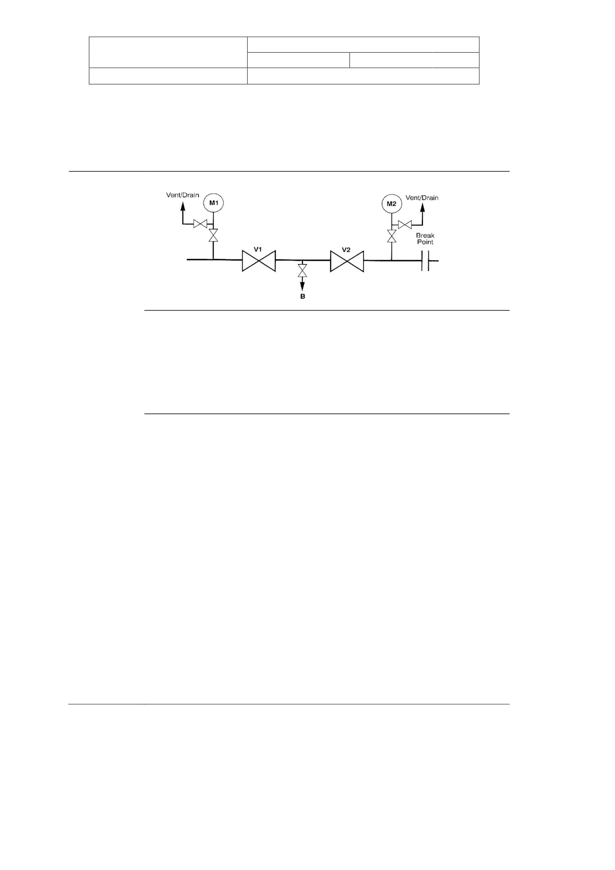
Title: Energy Isolation - Process
Doc No: UNIF-HSE-PRO-107-C2
Rev No: C2
Page 33 of 36
Dated: September, 2004
Originating Dept: HSE
APPENDIX D - TYPICAL VALVE ISOLATIONS INTEGRITY TESTS
Double Block and Bleed Isolation Integrity Test (Two Valves)
Diagram
Key
V1 - First (upstream) isolation valve from live system.
M1 - Live side-monitoring point (pressure gauge or vent/drain).
V2 - Second (downstream) isolation valve from live system.
M2 - Monitoring point between valves and break point (pressure gauge or vent/drain).
B - Bleed point between the isolation valves.
Procedure
1. If possible, ensure tapings at M1, M2 and B are not blocked and pressure
gauges, where installed, are operating.
2. Close downstream valve V2 and secure in closed position.
3. Record pressure at monitoring points M1 and M2.
4. Vent/drain section of line to be broken and monitor at M2 until the pressure is
near zero.
5. Close vent/drain at break point and monitor at M2 for a minimum of 10 minutes.
No pressure build-up at M2 indicates the integrity of the downstream valve V2.
6. Close upstream valve V1 and secure in closed position.
7. Record pressure at M1 and B.
8. Vent/drain between V1 and V2 (B) and monitor at B until pressure is near zero.
9. Close vent/drain (B) and monitor at M1 and B for a minimum of 10 minutes. (No
pressure build-up at B indicates integrity of upstream valve V1).
10. Leave vent/drain (B) in closed position to allow further monitoring.
Isolation
Both block valves are now closed and secured. The bleed valve is closed but not
Summary
locked. It is possible for pressure to build up between the two block valves therefore
regular monitoring of the isolation is essential; a suitable calibrated pressure gauge
may be fitted to the vent to monitor for any pressure.
For further information refer to Section C1.2.2 Double Block and Bleed
The controlled version of this document can be found at: http://baku.bpweb.bp.com/dep/hse/safe/
Next Revision Date: 30/09/2005
Print Date: 24/07/2010
PAPER COPIES ARE UNCONTROLLED. THIS COPY VALID ONLY AT THE TIME OF PRINTING
Title: Energy Isolation - Process
Doc No: UNIF-HSE-PRO-107-C2
Rev No: C2
Page 34 of 36
Dated: September, 2004
Originating Dept: HSE
Isolation Integrity Test (BP-Approved Double Sealed, Single Valve)
Diagram
Key
M1 - Live (upstream) side monitoring point.
M2 - Monitoring point between valve and break point (downstream).
C - Cavity drain (between seals).
Procedure
1. If possible, ensure tapings at M1, M2 and C are not blocked and pressure
gauges, where installed, are operating.
2. Close isolation valve and secure in closed position.
3. Record pressure at M1, C (in cavity) and M2.
4. Vent/drain downstream section of line to be broken and monitor pressure at M2
until pressure is near zero.
5. Close vent/drain at break point and monitor at M2 and C for a minimum of 10
minutes. (No pressure build-up at M2 and no pressure fall-off at C indicates
integrity of downstream seal.)
6. Record pressure at M1 and C.
7. Vent/drain off fluid in cavity (between seals) and monitor at C until the pressure
is near zero.
8. Close cavity vent/drain (C) and monitor at M1 and C for a minimum of 10
minutes. (No pressure build-up at C indicates integrity of upstream seal).
9. Leave vent/drain C in closed position to allow further monitoring.
Isolation
The double sealed, single block valve is now closed and secured. The bleed valve is
Summary
closed but not locked. Any fluid passing through the upstream seal will be detected at
the cavity drain C. Regular monitoring of the isolation is therefore essential and a
suitable calibrated pressure gauge may be fitted to the vent to monitor the pressure.
For further information refer to Section C1.2.2 Double Block and Bleed
The controlled version of this document can be found at: http://baku.bpweb.bp.com/dep/hse/safe/
Next Revision Date: 30/09/2005
Print Date: 24/07/2010
PAPER COPIES ARE UNCONTROLLED. THIS COPY VALID ONLY AT THE TIME OF PRINTING
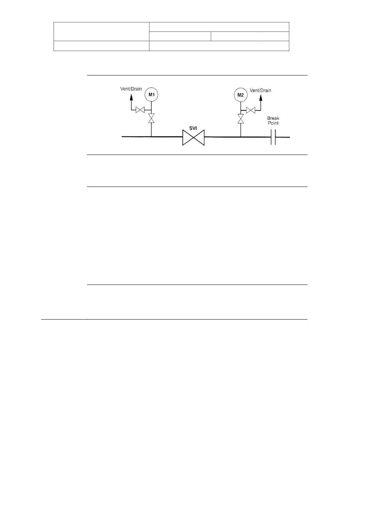
Title: Energy Isolation - Process
Doc No: UNIF-HSE-PRO-107-C2
Rev No: C2
Page 35 of 36
Dated: September, 2004
Originating Dept: HSE
Single Valve Isolation Integrity Test
Diagram
Key
M1 - Live (upstream) side monitoring point.
M2 - Monitoring point between valve and break point (downstream).
Procedure
1. Ensure tapings at M1 and M2 are not blocked and pressure gauges, where
installed, are operating.
2. Close isolation valve and secure in closed position.
3. Record pressure at M1 and M2.
4. Vent/drain downstream section of line to be broken into and monitor at M2
until pressure is near zero.
5. Close downstream vent/drain and monitor at M2 for a minimum of 10
minutes. (No pressure build-up at M2 indicates integrity of single valve.)
6. Leave downstream vent/drain at break point in closed position to allow
further monitoring.
Isolation
The single isolation valve is now closed and secured, and the downstream vent/drain
Summary
is closed. Any fluid passing through the single valve seal would be monitored by
means of the mandatory additional safeguards listed in Appendix B Table 1.
The controlled version of this document can be found at: http://baku.bpweb.bp.com/dep/hse/safe/
Next Revision Date: 30/09/2005
Print Date: 24/07/2010
PAPER COPIES ARE UNCONTROLLED. THIS COPY VALID ONLY AT THE TIME OF PRINTING
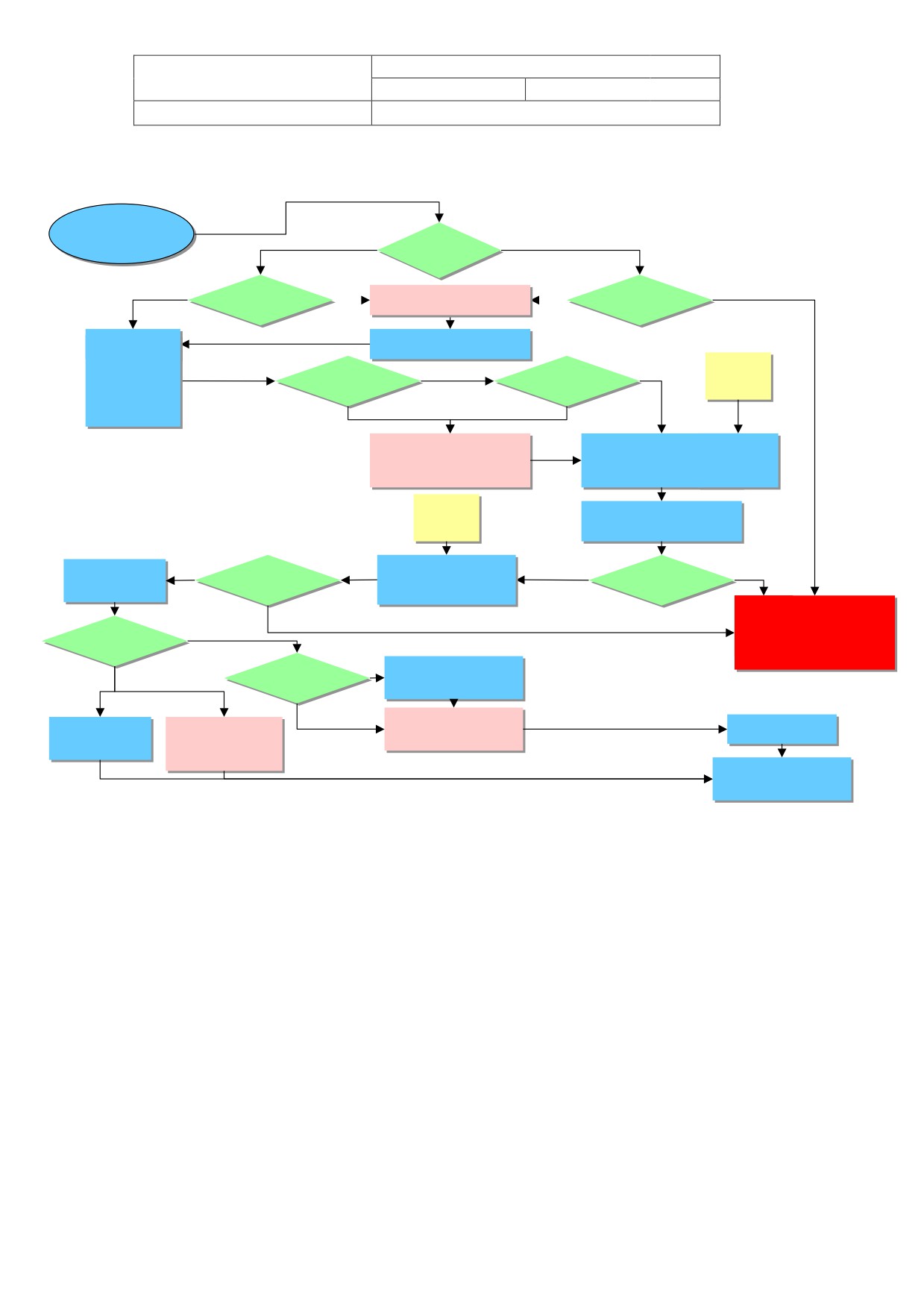
Title: Energy Isolation -
Doc No: UNIF-HSE-PRO-107-C2
Process
Rev No: C2
Page 36 of 36
Dated: September, 2004
Originating Dept: HSE
APPENDIX E - ENERGY ISOLATIONS FLOWCHART
Requirement
for
Isolation
No
Is this
Yes
a CSE?
Is this
Positive
No
Yes
Assess breaking
Yes
No
breaking
isolation
Containment risks/hazards
co
tainment?
available?
Define cleaning / flushing /
purging method
Select
Is this a
Can minimum
No
Yes
ICC
Isolation
Special isolation
Isolation standard
method
technique
be ac
ieved
Yes
No
L2RA
Install initial isolation
ICC
Complete draining / flushing /
Purging of eqpt where necessary
Isolation
Progress work, monitor
Yes
Install final
Yes
Isolation
No
successfully
isolation integrity
isolation
roved?
roved?
STOP
No
Reassess and consider
Yes
production shutdown,
Job complete
lleak test req‟d?
deferral of work and
further risk assessment
Is leak test
No
No
Prepare specific
covered by existing
Leak test procedure
rocedure
Yes
Carry out appropriate
Carry out leak test
Service test for
Service test for
Level of risk assessment
And record results
Non-haz utilities
Process hydrocarbons.
Mandatory L2RA
Fully de-isolate and
return to service
The controlled version of this document can be found at: http://baku.bpweb.bp.com/dep/hse/safe/
Next Revision Date: 30/09/2005
Print Date: 24/07/2010
PAPER COPIES ARE UNCONTROLLED. THIS COPY VALID ONLY AT THE TIME OF PRINTING
AZERBAIJAN BUSINESS UNIT
(AzBU)
Procedure for:
Confined Space Entry
Issued
C2
09.09.2004
G.Stacey
SsoW WG
N. McCleary
G. Campbell
for use
Rev
Date
Reason
Prepared by
Checked by
Approved by
Endorsed by
for Issue
Notes: C2: Updated to
HSE - SAFETY
provide more clarity and detail
Azerbaijan BU Document Reference
Asset Code
Dept Code
Document Type
Sequence No
Revision Code
UNIF
HSE
PRO
108
C2
The controlled version of this document can be found at: http://baku.bpweb.bp.com/dep/hse/safe/
Next Revision Date: 30/09/2005
Print Date: 24/07/2010
PAPER COPIES ARE UNCONTROLLED. THIS COPY VALID ONLY AT THE TIME OF PRINTING
Title: Confined Space Entry
Doc No: UNIF-HSE-PRO-108-C2
Procedure
Rev No: C2
Page 2 of 31
Dated: September, 2004
Originating Dept: HSE
TABLE OF CONTENTS
1.0 INTRODUCTION
3
2.0 ROLES AND RESPONSIBILITIES
6
3.0 AUDITING AND MONITORING
10
4.0 COMPETENCY, TRAINING AND AWARENESS
11
5.0 PLANNING AND PROCEDURE
13
6.0 WELDING
21
7.0 CONFINED SPACE PLANNING FLOW-SHEET
21
8.0 JOB COMPLETION
21
9.0 RESCUE
23
APPENDIX A: DEFINITIONS AND ABBREVIATIONS
24
APPENDIX B: HAZARDS ASSOCIATED WITH CONFINED SPACES
26
APPENDIX C: PERSONAL PROTECTIVE EQUIPMENT
28
APPENDIX D: EXAMPLES OF A CONFINED SPACE
30
APPENDIX E: EXAMPLES OF A RESCUE PLAN
31
The controlled version of this document can be found at: http://baku.bpweb.bp.com/dep/hse/safe/
Next Revision Date: 30/09/2005
Print Date: 24/07/2010
PAPER COPIES ARE UNCONTROLLED. THIS COPY VALID ONLY AT THE TIME OF PRINTING
Title: Confined Space Entry
Doc No: UNIF-HSE-PRO-108-C2
Procedure
Rev No: C2
Page 3 of 31
Dated: September, 2004
Originating Dept: HSE
1.0
INTRODUCTION
1.1
Purpose
The purpose of this procedure is to:
Identify and define confined spaces
Describe the proper procedures and preparations to protect the health and safety of
all personnel who must work in confined spaces.
1.2
Deviations
The procedures are written in sufficient detail that they should be able to be applied
consistently at all sites. There may still be the requirement for some local rules covering site
specific logistical/administrative arrangements and local variations in responsibilities to
reflect differences in organisational arrangements. These local rules should not deviate from
the core processes within this document. Any form of deviation from this procedure,
including but not limited to local rules, shall be requested and authorised in accordance with
the SSOW Deviations from Regulations and Procedures procedure (Doc. No. UNIF-HSE-
PRO-101)
1.3
Scope
The scope covers defined activities of BP and Contractors at all BP AzBU sites and
installations.
1.4
Document Review
This document will be reviewed on an annual basis when users from the sites will have an
opportunity to propose changes to the existing processes and procedures. The document
Technical Authority will be responsible for coordinating this review.
1.5
SSOW Specific Cross references
This SSOW procedure shall, where appropriate, be used in conjunction with this suite of
AzBU SSOW Procedures referenced below.
Document Number
Title of Procedure
UNIF - HSE- PRO - 101
Deviations from Regulations and Procedures
UNIF - HSE- PRO - 102
Incident Investigation and Reporting
UNIF - HSE- PRO - 103
Permit To Work
UNIF - HSE- PRO - 104
Authorization
UNIF - HSE- PRO - 105
Task Risk Assessment
UNIF - HSE- PRO - 106
Energy Isolations-Electrical
UNIF - HSE- PRO - 107
Energy Isolations-Process
UNIF - HSE- PRO - 108
Confined Space Entry
UNIF - HSE- PRO - 241
Leak Testing
The controlled version of this document can be found at: http://baku.bpweb.bp.com/dep/hse/safe/
Next Revision Date: 30/09/2005
Print Date: 24/07/2010
PAPER COPIES ARE UNCONTROLLED. THIS COPY VALID ONLY AT THE TIME OF PRINTING
Title: Confined Space Entry
Doc No: UNIF-HSE-PRO-108-C2
Procedure
Rev No: C2
Page 4 of 31
Dated: September, 2004
Originating Dept: HSE
1.6
BP Golden Rules
Entry to Confined Spaces is covered specifically by one of BP‟s 8 Golden Rules, which
states:
“Entry to such spaces must be controlled, and only authorised following a risk assessment
and the establishment of controls over the hazards. The actual detailed permitting
requirements will be based on local rules and national regulatory requirements, the
frequency of entry, and full knowledge of the hazards present”
1.7
Caution
A Level 2 Risk Assessment (L2RA) must be completed before any entry into a
confined space (See UNIF-HSE-PRO-105).
The Risk Assessment should identify the:
The Process and Electrical positive Isolation of the area to be entered
Sequence of work to be performed in the confined space for which a separate permit
to work is mandatory
Specific hazards known or anticipated
Control measures to be implemented to eliminate or reduce each of the hazards to an
acceptable level.
In order to allow a gas tester to test the atmosphere in a confined space a Confined
Space Entry Permit must be issued - the gas tester then records the concentrations of
gas found and signs that the atmosphere is safe for people to enter. The Confined
Space Entry Permit may then be used with a Permit to Work to control the work in the
Confined Space
No entry shall be permitted until the Risk Assessment and the completed Confined Space
Entry (CSE) Permit and the appropriate Permit to Work have been reviewed and discussed
in a Toolbox Talk by all persons engaged in the activity.
1.8
Definition
A confined space is a place which is substantially, though not always entirely, enclosed and
where serious injury can occur from hazardous substances or conditions within the space or
nearby. This includes large pipelines, tanks, vessels, separators, silos, ducts, sewers, pits,
flues, manholes and voids between modules and in legs on offshore Installations. It also
includes any space in which dangerous levels of contaminants can accumulate and
ventilation is restricted, eg excavations
(normally deeper than 1.2m), the space above
floating roofs on floating roof tanks, open-topped tanks, closed or unventilated rooms,
sumps and culverts, and any other poorly ventilated areas.
The controlled version of this document can be found at: http://baku.bpweb.bp.com/dep/hse/safe/
Next Revision Date: 30/09/2005
Print Date: 24/07/2010
PAPER COPIES ARE UNCONTROLLED. THIS COPY VALID ONLY AT THE TIME OF PRINTING
Title: Confined Space Entry
Doc No: UNIF-HSE-PRO-108-C2
Procedure
Rev No: C2
Page 5 of 31
Dated: September, 2004
Originating Dept: HSE
The hazards that this document addresses arise through the confined nature of the place of
work in combination with one or more of the following:
1. The possible presence of flammable and/ or toxic substances
2. An oxygen-deficient atmosphere
3. An oxygen-enriched atmosphere
4. Ingress of solids or liquids
5. The presence of excessive heat
For more information on hazards associated with CSE see Appendix B.
1.9
Language Facilitation
Due to the various languages spoken at site, there is a necessity to assist all with “an ease
of understanding”. Therefore, the development and use of information tools are available.
The controlled version of this document can be found at: http://baku.bpweb.bp.com/dep/hse/safe/
Next Revision Date: 30/09/2005
Print Date: 24/07/2010
PAPER COPIES ARE UNCONTROLLED. THIS COPY VALID ONLY AT THE TIME OF PRINTING
Title: Confined Space Entry
Doc No: UNIF-HSE-PRO-108-C2
Procedure
Rev No: C2
Page 6 of 31
Dated: September, 2004
Originating Dept: HSE
2.0
ROLES AND RESPONSIBILITIES
Note: For all confined space work, the responsibility for safety, during the entire operation,
rests with the Performing Authority, Confined Space Attendant, Authorised Entrants
and Rescue Team personnel. These personnel must ensure that adequate steps
have been taken to eliminate or control the hazards present.
2.1
OIM / Site Controller / Site Manager
Is responsible for the implementation of this Safe System of Work procedure on all his/her
facilities. This includes the training of staff and contractors in the use of the procedure and
the keeping of records. The OIM/Site Controller is responsible for ensuring the competence
of all authorities involved in Confined Space Entry Permit work. He must approve the
outcome of the Level 2 Risk Assessment (see UNIF-HSE-PRO-105)
2.2
Area Authority (AA)
Area Authorities are responsible for:
Identifying and labelling all confined spaces existing within their areas of responsibility that
require a Confined Space Permit to enter
Ensuring all persons involved in confined space entry work have received
appropriate training and certification
Leading the Level 2 Risk Assessments for Confined Space Entry (CSE) operations
to ensure personnel are protected from confined space hazards, using a Level 2
Risk Assessment (see UNIF-HSE-PRO-105)
Issuing the Entry Permit and Permit to Work authorising entry for the work to begin
(provided that the requirements of this procedure have been met)
Cancelling or suspending the Confined Space Entry (CSE) Permit when the job is
complete or when unacceptable conditions arise.
2.3
Performing Authority
The Performing Authority shall:
Know and recognise hazards that may be faced during entry by participating in a
Level 2 Risk Assessment before entry
Ensure that he understands all the conditions on the PTW and cross-referenced
Certificates and signs to confirm his responsibility for complying with all the conditions
on the Permit
Ensure that roles and responsibilities are effectively communicated to ensure the
competence of the workforce - including leading a toolbox talk
Ensure that personnel entering a confined space have all necessary personal
protective equipment
Ensure that rescue services are informed about the entry and that they are readily
The controlled version of this document can be found at: http://baku.bpweb.bp.com/dep/hse/safe/
Next Revision Date: 30/09/2005
Print Date: 24/07/2010
PAPER COPIES ARE UNCONTROLLED. THIS COPY VALID ONLY AT THE TIME OF PRINTING
Title: Confined Space Entry
Doc No: UNIF-HSE-PRO-108-C2
Procedure
Rev No: C2
Page 7 of 31
Dated: September, 2004
Originating Dept: HSE
available in an emergency
Ensure that the necessary rescue and resuscitation equipment are readily available
Ensure acceptable safe entry conditions are maintained consistent with the terms of
the Confined Space Entry (CSE) Permit.
Stop work and remove everyone from the confined space if the conditions of entry,
including the scope of work, change
2.4
Gas Tester
Approved persons who have been fully trained and certified in gas testing for confined space
entry purposes, i.e. Authorised Gas Tester Level 1 (AGT1), Is trained to gas test prior to
work in confined spaces.
There are two levels of AGT - 1/2. Only AGT1 can test for CSE.
The AGT1 shall:
Prove the safe atmosphere (i.e. free of toxic and flammable gases) in the confined
space using correctly calibrated gas testing equipment in his charge with an
understanding of the limitations of the equipment
Prove Oxygen Levels within levels required
Enter the readings obtained while testing the atmosphere in the Confined Space onto
the Confined Space Entry Permit
If the atmosphere is within the acceptable limits for entry, sign section 8 of the Work
Permit.
Where the gas concentrations are outside the acceptable limits sign the permit to this
effect discuss with the Area and Performing Authorities measures to further purge
the space.
Observe and record any sludge or scale in the Confined Space and record it on the
Confined Space Permit ensuring that the findings are clear and easy to read.
2.5
Authorised Entrants
The authorised entrants shall:
Follow established safety standards and practices
Participate in a Toolbox Talk
Read the conditions required by the Confined Space Entry Permit and the associated
Permit to Work
Know and recognise the hazards that may be faced during entry including signs or
symptoms, and consequences of the exposure
Inspect, test and make proper use of equipment and protective devices
Maintain communication with the Confined Space Attendant to enable the attendant
to monitor the entrants‟ status
Alert the attendant if an unsafe condition exists or when symptoms of exposure
The controlled version of this document can be found at: http://baku.bpweb.bp.com/dep/hse/safe/
Next Revision Date: 30/09/2005
Print Date: 24/07/2010
PAPER COPIES ARE UNCONTROLLED. THIS COPY VALID ONLY AT THE TIME OF PRINTING