Military reference books and manuals (2009-2023, Volume 5) - page 42
SW820-AP-MMI-010
REVISION 15
27 MARCH 2009
CHAPTER 4
4.15.2.3
5-Cell Strikedown Module. The 5-cell strikedown module replaces three cells with a
crane on an elevator, both hydraulically operated. The crane is used for maintenance, loading
STANDARD Missile-2 BLK II and VLA canisters, removing empty canisters and reconfiguring
cells. The crane is stowed inside the module when not in use.
4.15.3
Remote Launch Enable Panel (RLEP). The RLEP (Figure 4-27 "Remote Launch
Enable Panel (RLEP)"⇒), located in the Combat Information Center (CIC), interfaces directly
with the status panel and is used to control Remote Launch Enable and Remote Magazine Power
Enable signals when the status panel permits remote operation.
4.15.4
Status Panel. The status panel (Figure 4-28 "Status Panel"⇒) receives and displays
module status and launcher hazard signals from sensors within the launcher, forwards such
signals to the Central Control Station (CCS), and receives enable signals from the RLEP to enable
launcher enable power and launch enable functions within the launcher when the CONTROL
key-switch is set to REMOTE.
4.15.5
TOMAHAWK Weapon Control System (TWCS). The TWCS is a general purpose
computer system that receives track and target data from weapon and sensor systems from own
and other ships. Targets are selected by operators for engagement by the VLS. Missile select
commands, target related data, and launch commands are transmitted to the VLS for launch
control. The VLS provides the TWCS with missile inventory and equipment availability status.
The TWCS is comprised of two functional groups: Track Control Group and Launch Control
Group.
4.15.5.1
Track Control Group (TCG). The TCG performs targeting and track data processing,
threat evaluation and weapon assignments using an Operator Interactive Display Terminal and
TCG Preprocessor Control Center, Data Processor Control Center and Data Storage Control
Center equipment.
4.15.5.2
Launch Control Group (LCG). The LCG receives engagement plans and launch
orders from the TCG to prepare, control, evaluate and launch TCMs using Operator Interactive
Display Terminals and LCG Data Processor Control Center and Data Storage Control Center
equipment. The LCG also provides direct interface with LCU data processors.
4.16 ONLOAD, OFFLOAD AND CROSSDECK WEAPONS.
This paragraph provides general information regarding preparation for, and onload and offload of
weapons as well as offload of a spent canister. Technical manual SW394-EE-PRO-010 contains
the procedures for shore base personnel to prepare the weapon for onload and to perform weapon
onload or offload. Technical manual SW394-AF-MMO-050 provides a detailed discussion of on
board procedures for: preparing launchers and cells for onload and offload; securing weapons in
launch cells; preparing weapons/canisters for offload; and activating launchers upon completion
of operations.
4.16.1
Onload. Ship onload begins when the ship arrives at a designated shore activity to
receive a complement of weapons. Wind and sea motion, which affect the ship’s position and
movement, are factors in determining the feasibility of loading operations. The shore base loading
supervisor and the ship’s commanding officer will determine if conditions are satisfactory prior
228
SW820-AP-MMI-010
REVISION 15
27 MARCH 2009
CHAPTER 4
to commencing onload. Prior to onload, launchers are neutralized and placed in the strikedown
mode at the status panel. During onload, responsibility for operations is shared between the ship’s
commanding officer and the shore base loading supervisor. All actions involving ship system
preparation are the responsibility of the ship’s commanding officer. His permission is required
prior to commencing loading operations. His designated representative is responsible for weapon
handling operations and ensures that a weapon transfer inspection is conducted. Upon completion
of ship preparation, responsibility for loading transfers to the shore base loading supervisor. The
ship’s crew conducts the final hookup and closeout of the launcher upon disconnect and removal
of the loading equipment. The following paragraphs provide a general overview of procedures
used during loading operations. For purposes of illustration, loading of a generic weapon into one
launcher is discussed. For multiple loadings, the procedures are the same except that multiple
actions may be occurring simultaneously to prepare launch cells and weapons. Additionally,
loading equipment is moved from missile to missile until the full complement of weapons is
aboard the ship. Similarly, post-loadout is accomplished on a cell by cell basis until full closeout
is accomplished. Onload terminates when the ship has received its scheduled complement, final
hookup has been accomplished, all loading equipment has been removed, cell hatches are closed
and secured, and ship system equipment has been activated.
4.16.1.1
Prepare Launcher. Launcher preparations include preparing below-deck and
above-deck areas for loading. The launcher entry procedure takes the launcher offline, puts
the launcher in strikedown, ensures power is available to strikedown controls, and, if required,
performs launcher blowout to ensure residual launch gases are not present in the plenum area.
In addition, the launcher crew performs the prior-to-use inspection of torque tools to be used to
undog and dog the dogdown latches. The above-deck preparations include positioning required
handling equipment and ensuring the area is free of unnecessary equipment.
4.16.1.2
Prepare Cell. Cell preparation may include the requirement to transfer weapons
between cells prior to commencing onload of new weapons. This may be necessitated by the need
for certain missiles to be located in certain cells for accessibility to telemetry connections or the
Critical Function Interrupt Switch. Transfer of missiles between cells may involve removal and/or
installation of sill assemblies, canister adapters and plenum cell covers. Exact requirements for
tasks to be performed are dictated by the types of missiles to be transferred between cells.
4.16.1.3
Prepare Weapon. As the launchers and cells are being prepared for onload, shore base
personnel prepare the weapon for loading. If using a Mk 3 Horizontal Strongback, the strongback
is installed and secured to the canister. A crane hook is attached to the strongback lifting shackle,
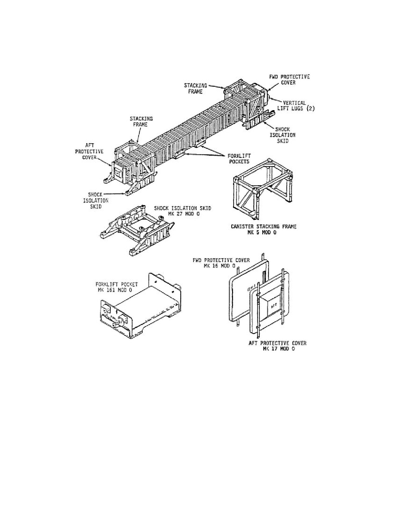
and the canister is raised to remove the packaging, handling, storage, and transport (PHS&T)
equipment (Figure 4-29 "Mk 14 VLS Canister PHS&T Equipment"⇒) from the canister. If a
forklift is used, the fork tines are inserted into the canister forklift channels, the canister is raised
and all PHS&T equipment except the forklift channels are removed. FWD and AFT protective
covers are removed. The canister is then moved to, and secured on, the Tilt Fixture, Mk 23 Mod 0
with Kit A (Figure 4-30 "Secure Canister to Mk 23 Tilt Fixture"⇒) in the horizontal position.
The strongback or forklift and forklift channels are removed.
4.16.1.4
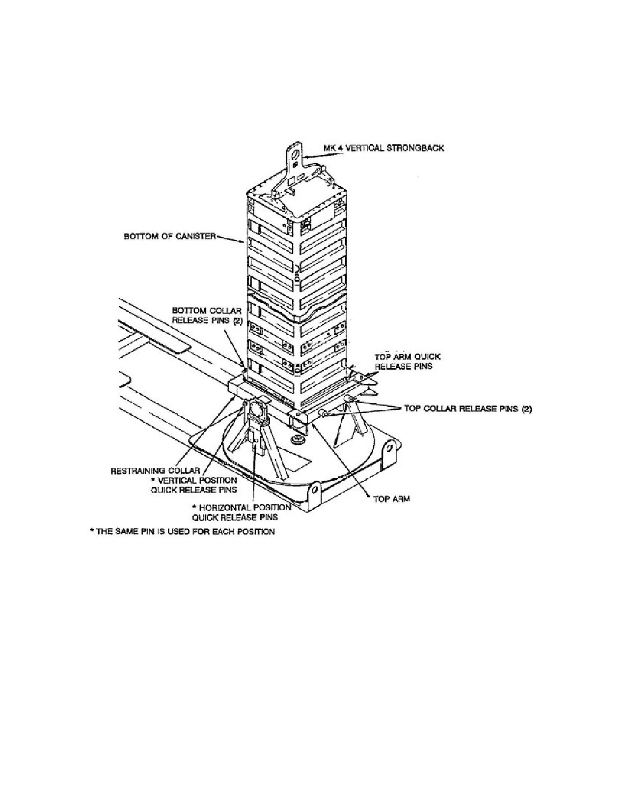
Load Weapon. The Mk 4 Vertical Strongback is installed on the FWD canister lifting
lugs. Pins securing the canister in the horizontal position are removed and the canister is raised to
229
SW820-AP-MMI-010
REVISION 15
27 MARCH 2009
CHAPTER 4
the vertical position (Figure 4-31 "Upright Mk 14 VLS Canister to Vertical Position"⇒). Pins
securing the canister to the tilt fixture are removed and the canister is raised and positioned over
the launch cell. The canister is oriented so that the umbilical connector will be on the walkway
side of the canister when installed in the launch cell. The canister is slowly lowered into the
launch cell until the bottom of the canister contacts the sill assembly. The strongback is removed
from the canister and lowered to the pier. The canister is secured in the cell and connected to the
electronic circuitry of the VLS and the deluge system.
4.16.1.5
Post-Loadout. Post-loadout is the reactivation of the launcher. This process brings
the launcher back on line and able to launch missiles. It includes returning power to the launch
sequencer and taking the launcher out of strikedown mode at the status panel.
4.16.2
Offload. Ship offload begins when the ship arrives at a designated shore base activity to
discharge a complement of weapons or expended canisters. Wind and sea motion, which affect the
ship’s position and movement, are factors in determining the feasibility of offloading operations.
The shore base loading supervisor and the ship’s commanding officer will determine if conditions
are satisfactory prior to commencing offload. Prior to offload, launchers are neutralized and
placed in the strikedown mode at the status panel. During offload, responsibility for operations is
shared between the ship’s commanding officer and the shore base loading supervisor. All actions
involving ship system and weapon preparation are the responsibility of the ship’s commanding
officer. His permission is required prior to commencing offloading operations. His designated
representative is responsible for weapon handling operations and ensures that a weapon transfer
inspection is conducted. Upon completion of ship and weapon preparation, responsibility for
offload transfers to the shore base loading supervisor. The following paragraphs provide a general
overview of procedures used during offload operations. For purposes of illustration, offloading
of a generic weapon from one launch cell is discussed. For multiple offloads, the procedures
are the same except that multiple actions may be occurring simultaneously to prepare launch
cells and weapons. Additionally, loading equipment is moved from missile to missile until the
full complement of weapons is offloaded from the ship. Similarly, post-offload procedures are
accomplished on a cell by cell basis until full closeout is accomplished. Offload terminates when
all weapons scheduled for offload have been removed from the ship.
4.16.2.1
Prepare Launcher. Launcher preparations include preparing below-deck and
above-deck areas for offload. The launcher entry procedure takes the launcher offline, puts the
launcher in strikedown, ensures power is available to strikedown controls, and, if required,
performs launcher blowout to ensure residual launch gases are not present in the plenum area.
In addition, the launcher crew performs the prior-to-use inspection of torque tools to be used to
undog and dog the dogdown latches. The above-deck preparations include positioning required
handling equipment and ensuring the area is free of unnecessary equipment.
4.16.2.2
Prepare Crane. If the offload involves expended Mk 14 Canisters, the shipboard
strikedown crane may be utilized for offload. Preparation of the crane includes bringing the crane
up to the 01 level and preparing it for operation.
4.16.2.3
Remove Weapon. The weapon is disconnected from all VLS electrical circuitry and
the deluge system. Additionally, all devices securing the canister in the cell are removed. The
230
SW820-AP-MMI-010
REVISION 15
27 MARCH 2009
CHAPTER 4
Mk 4 Vertical Strongback is installed on the FWD canister lifting lugs. The canister is slowly
extracted from the launch cell and swung outboard to the pier. The canister is oriented so that
the canister bottom faces the Tilt Fixture, Mk 23 Mod 0 with Kit A, FWD rest. The canister is
lowered to and locked on the tilt fixture. The canister is lowered to the horizontal position and the
Mk 4 Strongback is removed. The Mk 3 Horizontal Strongback or forklift channels/forklift are
installed, the canister is removed from the tilt fixture and PHS&T equipment is installed.
4.16.3
Crossdeck Weapons. Crossdecking of weapons is performed similar to onload and
offload except weapons may be transferred from one launcher to another aboard the same ship
or between different ships without lowering the weapon to the pier into the Mk 23 Tilt Fixture.
Crossdecking is accomplished using the Mk 4 Vertical Strongback and crane hook arrangement
to extract, transfer and insert weapons between launch cells.
4.17 OPERATIONAL CONSTRAINTS/RESTRICTIONS.
Tactical employment of the TCM imposes a number of constraints on the operating parameters of
the ship. The constraints imposed during tactical launch operations of the TOMAHAWK Cruise
Missile are provided in applicable tactical publications. Employment also places restrictions on
the ship’s tactical flexibility which are described in Operating Guidelines, tactical employment
manuals and operation manuals.
4.17.1
Weapon Mix. Weapon mix will depend on the particular conditions that exist at the time
the decision is made to prepare weapons for launch. The TWCS is capable of processing a
combination of TOMAHAWK Cruise Missile variants. Other weapons control systems are used
to launch STANDARD missiles and VLA. Prime consideration for selecting a specific weapon
for launch should be the time required to prepare and launch a single TCM. Additionally, the
VLS will neither select a TCM in a module with a launch in progress nor suspend a launch in
progress in order to support a TCM launch.
4.17.2
Weapon Availability. Various factors are used by the VLS to verify that a particular
TCM is available for selection. These factors summarize missile, cell and module status
conditions. A particular missile is available for selection if no availability factor applies. If any
factor does apply, the missile may still be available if the factor can be overridden. Table 4-1
"Missile Availability Factors"⇒ identifies availability factors and the capability for override.
4.18 LAND-ATTACK TCM OPERATIONAL SEQUENCE.
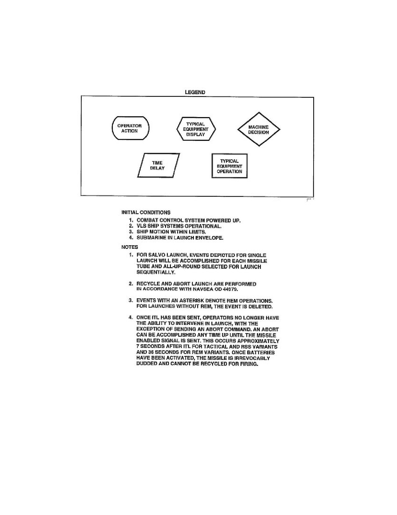
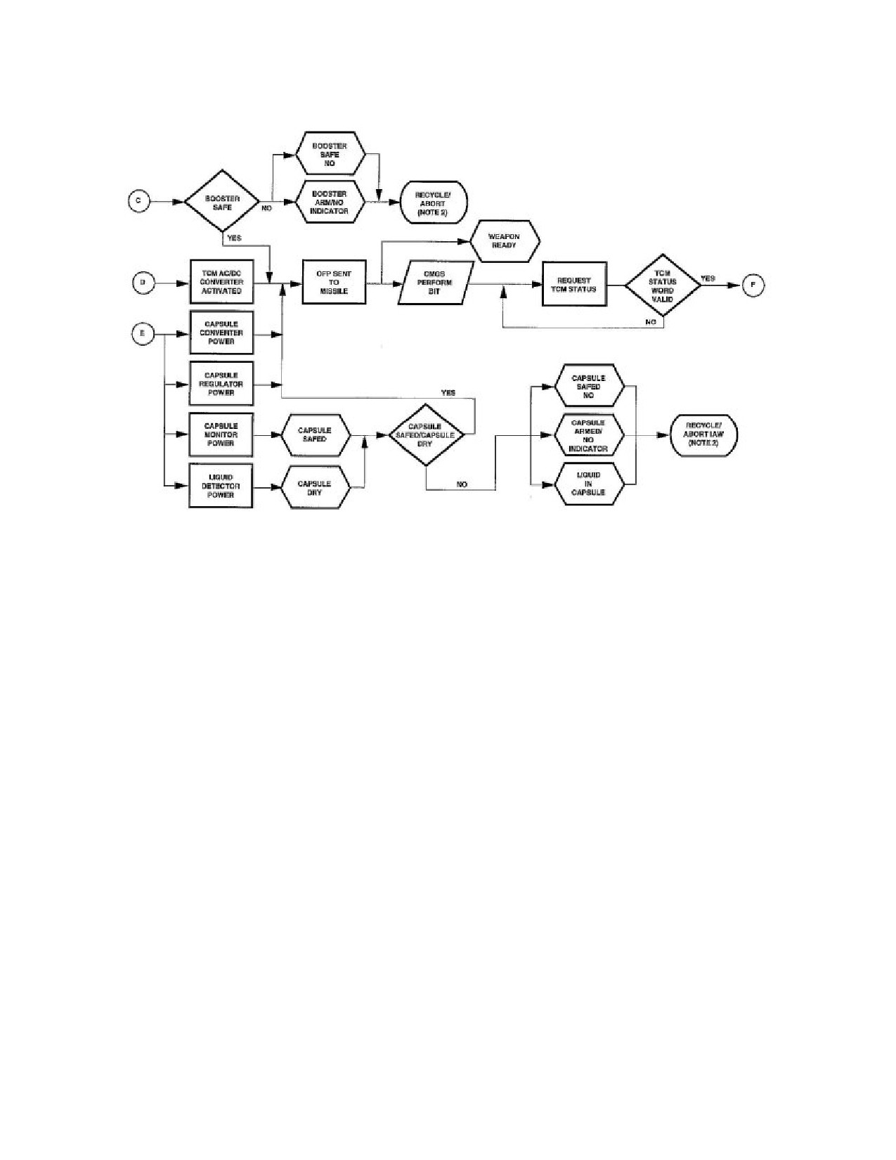
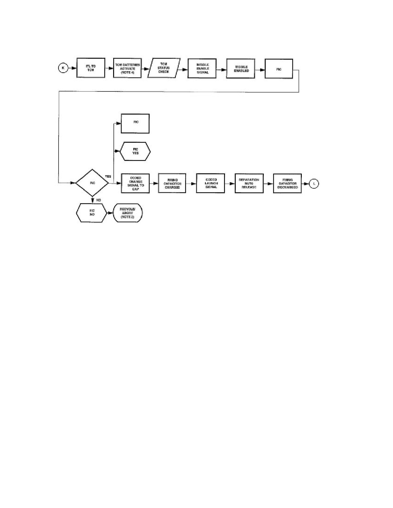
This paragraph describes typical actions and responses required to launch a land-attack TCM.
Primary coverage is given to normal launch of a single weapon. For multiple launch, the
operational steps for a single launch are sequentially accomplished for each weapon selected for
launch. Abnormal launch conditions and abort procedures are discussed by highlighting only
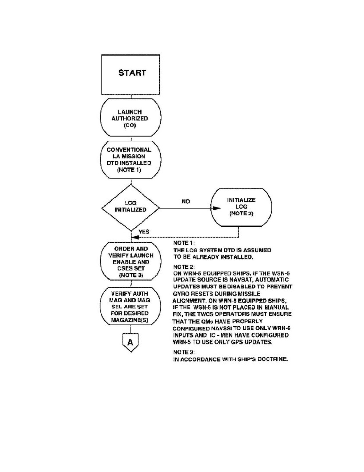
those events that differ from a normal launch. Typical launch operations are shown in Figure 4-32
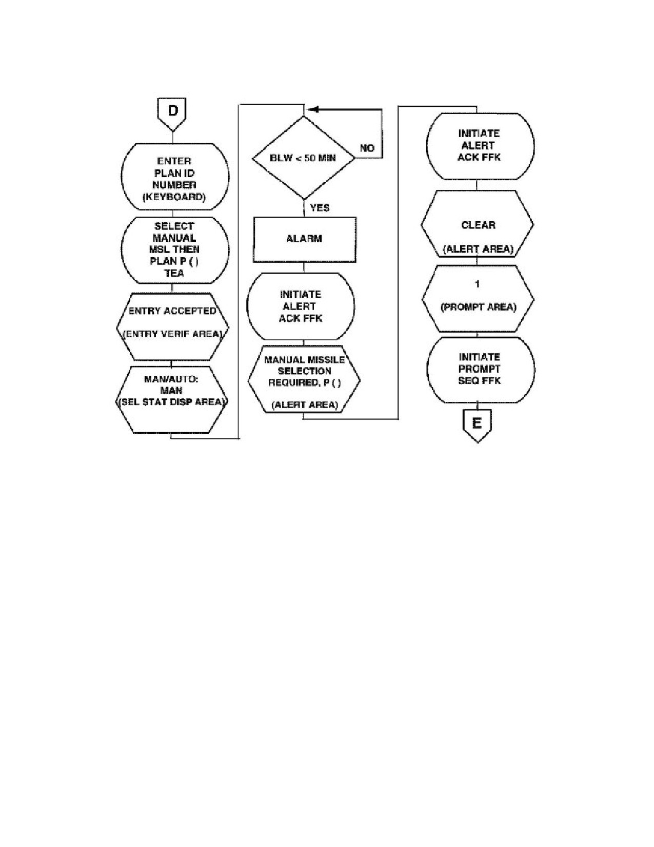
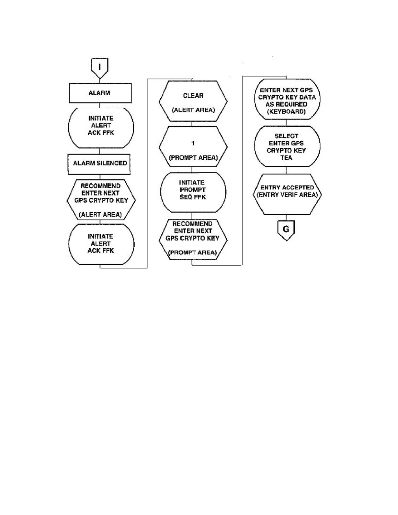
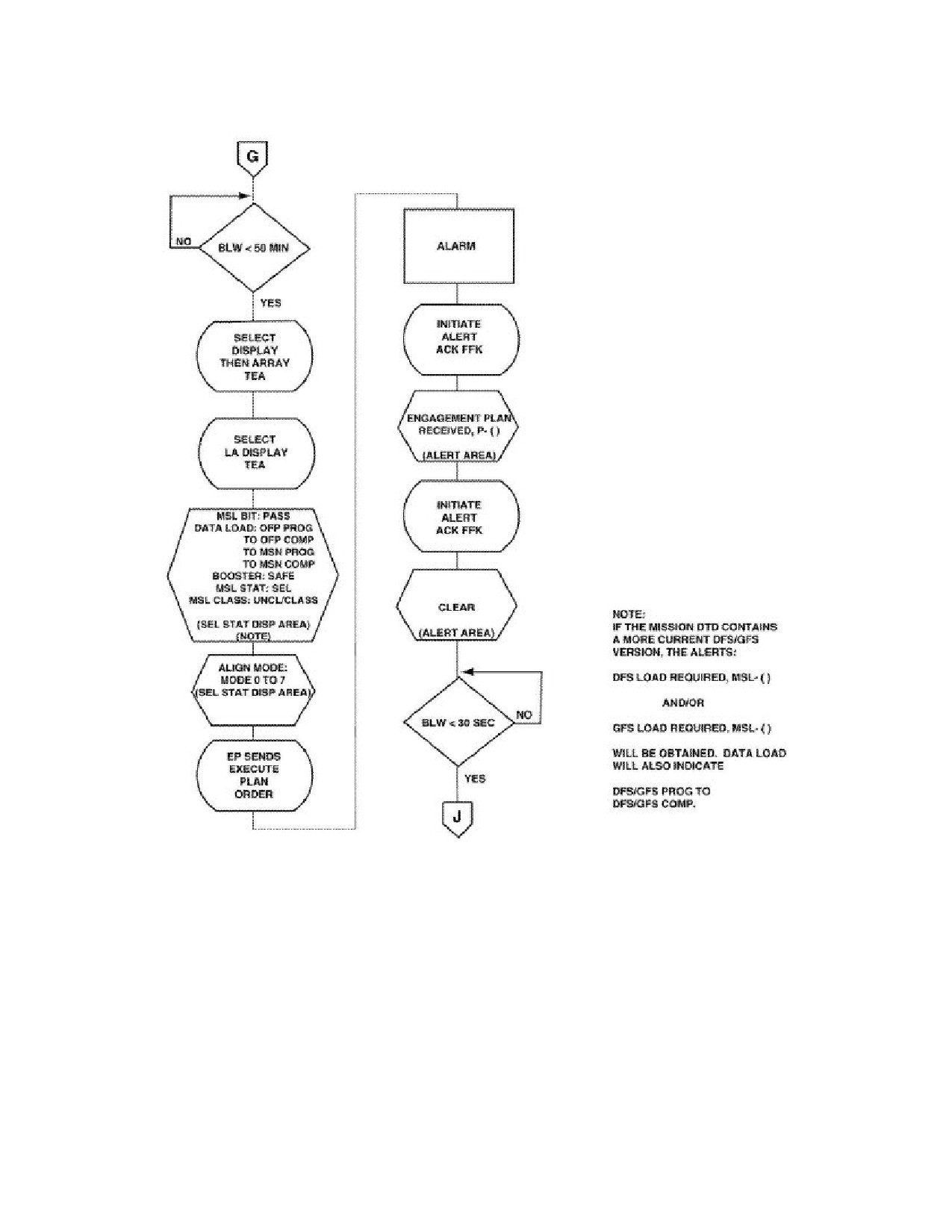
"RGM-109-4 Land-Attack TCM Operational Sequence (15 Sheets)"⇒. The figure illustrates the
orders given by the ship’s commanding officer, typical actions taken by equipment operators and
typical equipment operations, status displays and machine decisions. The operational sequence is
described in the following paragraphs. For a full discussion of operating procedures, as well as
actions to be taken under abnormal conditions, refer to SW261-DE-MMO-030.
231
SW820-AP-MMI-010
REVISION 15
27 MARCH 2009
CHAPTER 4
4.18.1
Prelaunch Reprogramming. Before Intent to Launch is signalled, the TWCS can
identify and reprogram land-attack Block III TCMs. During the reprogramming process, TWCS
issues a READY ALERT request to the VLS, issues a non-launch select order, and applies power
to the missile in the selected cell. The TWCS downloads mission information and updates
DSMAC and GPSS Flight Software. When download is complete, the missile is deselected,
power is removed and the TWCS orders the VLS to STANDBY.
4.18.2
Missile Selection. Missile selection is controlled by the MISSILE SELECT ORDER
issued by the TWCS. The TWCS may select a specific missile by launcher, module and cell
(WCS MISSILE SELECTOR ORDER) or the TWCS may designate a type missile and allow
the VLS to select the specific TCM to be launched (VLS MISSILE SELECT ORDER). Upon
receipt of the VLS MISSILE SELECT ORDER, the VLS selects the cell to be used for launch
based on the following:
a. The cell selected must have the least number of launches of those TCMs available.
b. The TCM must be in a module or half-module which contains the most available TCMs
with no TCM launch that has progressed beyond rocket motor arming.
c. If all modules or half-modules have the same number of TCMs available that satisfy a
and b above, the module or half-module with the lowest designation number is selected.
If the same number module in both forward and aft launchers can meet the criteria, the
forward magazine is selected.
4.18.3
Cell Selection. When the MISSILE SELECT ORDER is received by the launch control
unit (LCU), the LCU determines if the ordered TCM is available, confirms missile identification,
and sends cell identification, position and alignment data to the TWCS. The LCU also sends a cell
select message to the launch sequencer (LSEQ) and starts a 650-ms timer.
4.18.4
Cell/Missile Preparation. Upon receipt of the cell select order, the LSEQ begins to
prepare the cell and the missile for launch. The LSEQ performs a status check to verify missile
selection as well as warhead and rocket motor safed. If missile selection is not verified or
warhead and/or rocket motor safe indications are not received, the LSEQ takes no further action
until the LCU completes evaluation of the failure. With missile selection and warhead and rocket
motor safed verified, the LSEQ applies OPERATE POWER, and, if applicable, REM HEATER
POWER to the missile and starts a 400-ms timer. At the end of 400-ms delay, the LSEQ sends
a select response message to the LCU confirming the type missile and warhead selected. The
LSEQ continuously monitors missile functions and sends a failure message to the LCU if monitor
functions change to an improper condition.
4.18.5
Select Response Evaluation. If the LCU receives the select response message prior
to the end of the 650-ms delay, the LCU starts an 80 second clock and updates the missile
availability file. This delay is used to ensure that the TWCS remains in communication with the
LCU throughout the launch sequence. The 80 second delay is reset each time a valid message
pertaining to the selected missile is received from the TWCS. If 80 seconds pass without
receiving a message, the LCU sends an equipment failure status message and commences the
cell safing procedure.
232
SW820-AP-MMI-010
REVISION 15
27 MARCH 2009
CHAPTER 4
4.18.6
Mission Assignment. The appropriate mission disk pack is removed from secure storage
and mounted on the random access storage set (RASS). The disk pack serial number is entered
and the RASS initialized. With RASS initialized, the TWCS is ready to transmit missile and
alignment data messages to the missile via the LCU. THEATER, MPS, MISSION and VERIFY
codes are received from the appropriate authority and entered. Mission data are then indicated and
transferred to the central computer resident memory. The operator enters the target number and
the pre-established waypoints to that target are displayed. The operator reviews the mission data
and approximate flight path to the target and makes route alterations by introducing or deleting
waypoints. The operator then assigns the mission to the designated cell and a verification that
the mission is assigned to the correct cell is performed. Once a mission has been assigned, no
further modifications can be made without resetting the mission and then reentering the mission
number and verification code.
4.18.6.1
CMGS alignment begins automatically upon completion of a successful upload
of the Operational Flight Program (OFP). Alignment data are repeatedly sent about each
second during the prelaunch stage. A two-position alignment technique eliminates the need to
perform maneuvers at latitudes below 75°. Launches at latitudes above 75°, however, require
maneuvers to meet the alignment timeline. Upon completion of alignment, the CMGS provides
an ALIGNMENT COMPLETE message.
4.18.6.2
If CMGS computer built-in test (BIT) is not passed, or valid communications can
not be established or becomes lost with the CMGS computer, an alert message is provided. To
establish or restore communications, a controlled shutdown of the CMGS is performed and
missile electrical power recycled. The normal start-up sequence is then repeated and program load
reattempted. When program load is accomplished, the reprogram command is sent to the CMGS.
4.18.7
Rocket Motor Arm. When all data has been loaded into the CMGS, the TWCS orders
BOOSTER ARM via the LCU to the LSEQ. When this order is received by the LCU, the LCU
dedicates the half-module containing the selected missile to a TOMAHAWK launch and activates
the circuits necessary for launch. The LSEQ removes REM power, if applied, and prepares the
cell for firing. The cell and uptake hatches are opened and the plenum drain closed. The rocket
motor is then armed.
4.18.8
Missile Activation. After receiving the missile/module ready status message from the
LCU, the TWCS issues a MISSILE FIRE ORDER to the LCU. Upon receipt of this order, the
LCU issues a BATTERY ACTIVATE command to the TCM which causes the CMGS to terminate
alignment and activates missile batteries. When the batteries are fully operational, the TCM sends
a MISSILE ENABLE signal to the LSEQ. The LSEQ removes power to the TCM and reports
the missile enabled. The LCU sends a launch status message to the TWCS to report MISSILE
ENABLED. If the launch sequence is stopped after battery activation, the missile is dudded
and cannot be recycled for firing.
4.18.9
Rocket Motor Ignition and Missile Release. After receiving MISSILE ENABLED,
the TWCS send a BOOSTER IGNITION order to the LCU. Upon receipt of this order, the LCU
checks the status of current launches and waits until launch rate and priority requirements are
met before issuing the IGNITION command to the LSEQ. The LSEQ applies booster ignition
233
SW820-AP-MMI-010
REVISION 15
27 MARCH 2009
CHAPTER 4
voltages to the TCM causing the rocket motor to ignite. After rocket motor ignition and receipt
of the CLOSURE RUPTURE signal indicating the aft closure plate has been blown open, the
LSEQ applies power to detonate the explosive restraining bolts allowing release of the TCM.
When the canister forward closure is broken, the breakwire opens to send a MISSILE AWAY
signal to the LSEQ which, in turn, notifies the LCU of missile away.
4.18.10
Cell Safing. The cell safing sequence may begin at any time when an unsafe condition
is monitored, a launch sequence is terminated (ABORT command issued), interrupted (SAFE
command issued by the TWCS), or when a MISSILE AWAY signal is not sent (missile misfire
or restrained fire). During this sequence, the SAFE MISSILE command is sent, relays open to
disconnect power and data lines to the cell. In the case of a restrained fire, the deluge system is
activated. If missile batteries were activated prior to an unsuccessful firing attempt, missile
inventory is updated to reflect the unavailability of that TCM for launch. If batteries were not
activated, the TCM is placed in a 30-minute cool down period prior to being made available
for future launch.
4.19 POST-LAUNCH.
When the LSEQ receives the MISSILE AWAY signal, the LSEQ disconnects prelaunch cell
power and signals from the cell and cancels the missile/cell selection. After a delay to allow the
missile and exhaust gases to clear the launcher, cell and uptake hatches are closed.. The LCU
evaluates the launch and updates missile inventory and cell firing count to reflect the change in
status brought about by the launch.
4.20 LAND-ATTACK TCM CASUALTY MODE.
There is no casualty mode for land-attack TCM variants.
234
SW820-AP-MMI-010
REVISION 15
27 MARCH 2009
CHAPTER 4
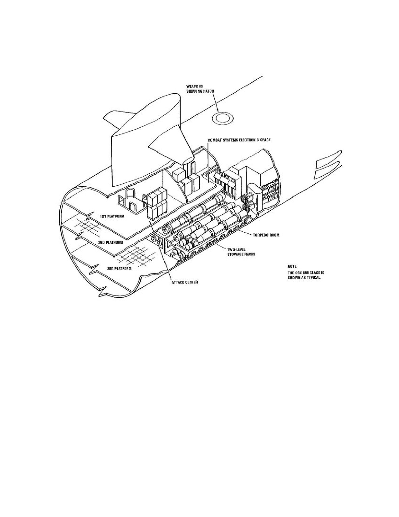
Figure 4-1. General Locations of SSN Complexes
235
SW820-AP-MMI-010
REVISION 15
27 MARCH 2009
CHAPTER 4
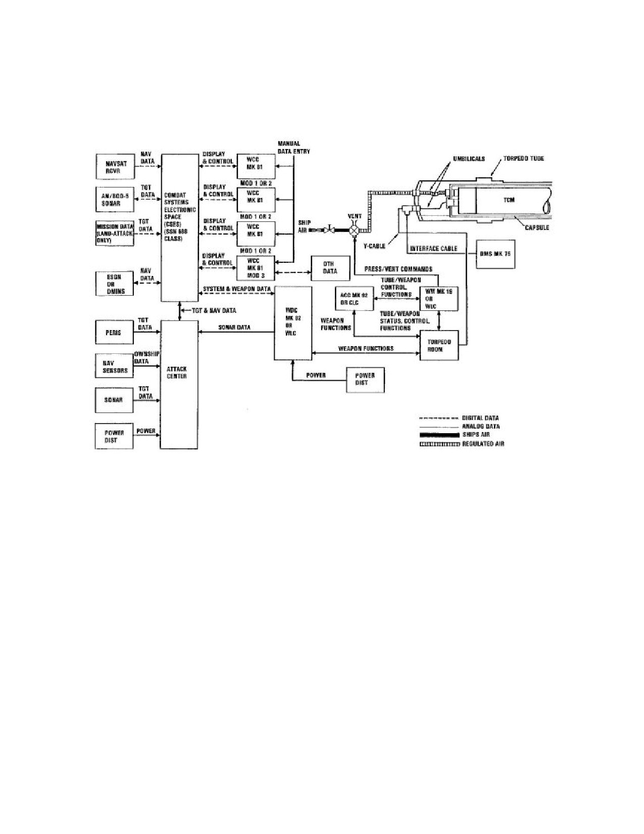
Figure 4-2. SSN/TWS-related Equipment TTL
Interfaces
236

SW820-AP-MMI-010
REVISION 15
27 MARCH 2009
CHAPTER 4
Figure 4-3. SSN TTL Pressurization/Vent Control
System
237

SW820-AP-MMI-010
REVISION 15
27 MARCH 2009
CHAPTER 4
Figure 4-4. MTEL Work Platforms
238

SW820-AP-MMI-010
REVISION 15
27 MARCH 2009
CHAPTER 4
Figure 4-5. TTL Weapon Shipping, Handling and
Stowage Equipment (SSN 688 Class)
239

SW820-AP-MMI-010
REVISION 15
27 MARCH 2009
CHAPTER 4
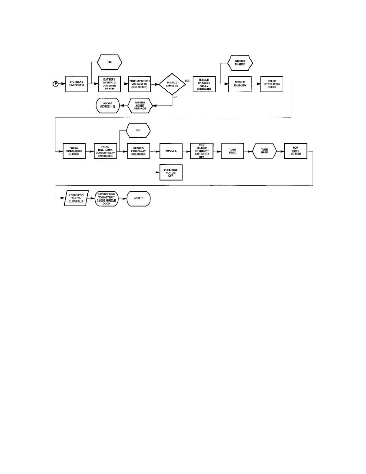
Figure 4-6. UGM-109-1 Land-Attack TCM
Operational Sequence (7 Sheets)
240

SW820-AP-MMI-010
REVISION 15
27 MARCH 2009
CHAPTER 4
241

SW820-AP-MMI-010
REVISION 15
27 MARCH 2009
CHAPTER 4
242

SW820-AP-MMI-010
REVISION 15
27 MARCH 2009
CHAPTER 4
243

SW820-AP-MMI-010
REVISION 15
27 MARCH 2009
CHAPTER 4
244

SW820-AP-MMI-010
REVISION 15
27 MARCH 2009
CHAPTER 4
245
SW820-AP-MMI-010
REVISION 15
27 MARCH 2009
CHAPTER 4
246

SW820-AP-MMI-010
REVISION 15
27 MARCH 2009
CHAPTER 4
Figure 4-7. MTEL With MTEL Adapter Installed
247
SW820-AP-MMI-010
REVISION 15
27 MARCH 2009
CHAPTER 4
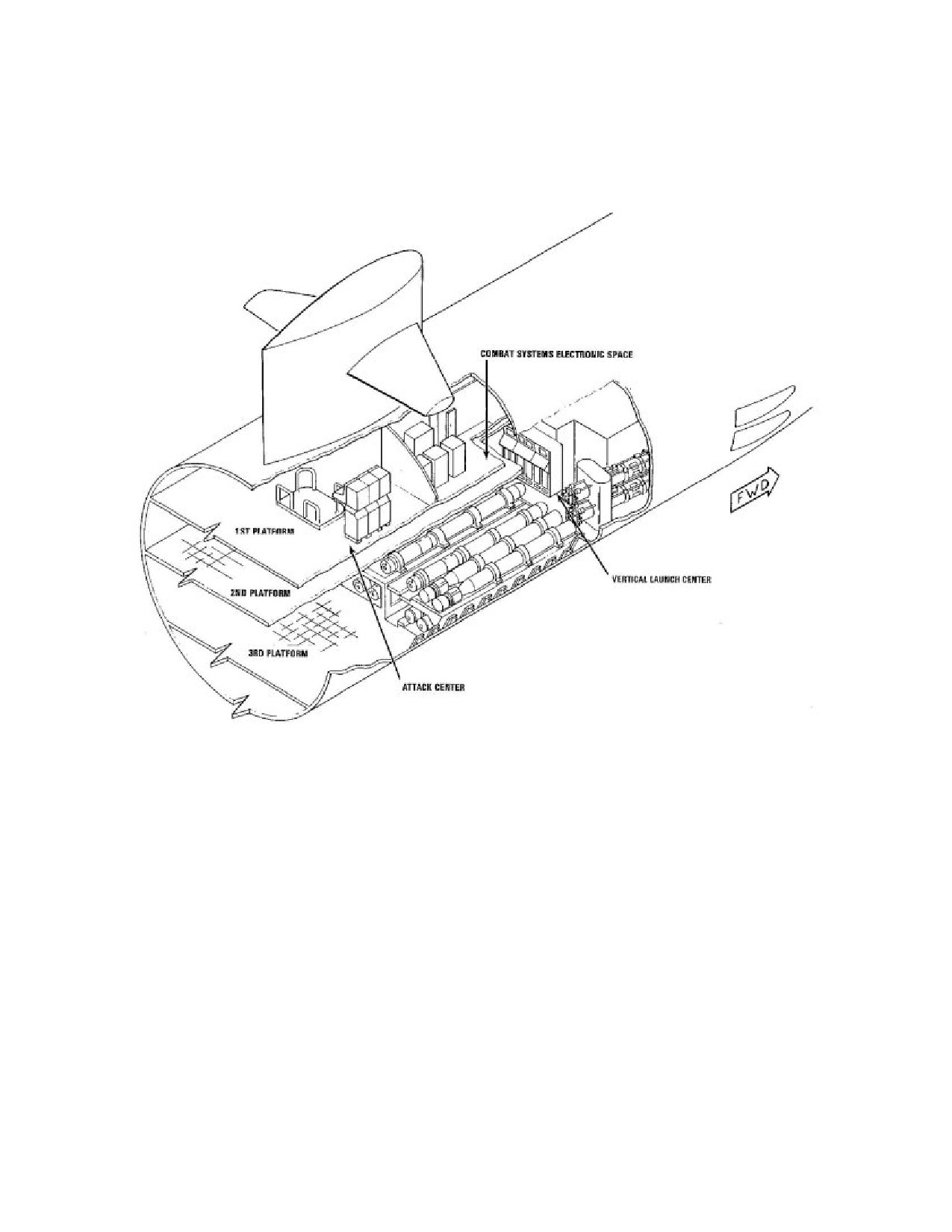
Figure 4-8. General Locations of SSN 688 Class
Submarine Complexes
248

SW820-AP-MMI-010
REVISION 15
27 MARCH 2009
CHAPTER 4
Figure 4-9. SSN 688 Class Submarine TWS-related
Equipment Interfaces (2 Sheets)
249

SW820-AP-MMI-010
REVISION 15
27 MARCH 2009
CHAPTER 4
250

SW820-AP-MMI-010
REVISION 15
27 MARCH 2009
CHAPTER 4
Figure 4-10. SSN 688 Class Submarine Missile Tube
Assembly
251

SW820-AP-MMI-010
REVISION 15
27 MARCH 2009
CHAPTER 4
Figure 4-11. SSN 688 Class Submarine Hydraulic
System
252

SW820-AP-MMI-010
REVISION 15
27 MARCH 2009
CHAPTER 4
Figure 4-12. SSN 688 Class Submarine
Pressurization/Vent System
253

SW820-AP-MMI-010
REVISION 15
27 MARCH 2009
CHAPTER 4
Figure 4-13. SSN 688 Class Submarine Flood and
Drain System
254

SW820-AP-MMI-010
REVISION 15
27 MARCH 2009
CHAPTER 4
Figure 4-14. SSN 688 Class Submarine Missile Tube
Control System
255

SW820-AP-MMI-010
REVISION 15
27 MARCH 2009
CHAPTER 4
Figure 4-15. Loading Platform Installed
256

SW820-AP-MMI-010
REVISION 15
27 MARCH 2009
CHAPTER 4
Figure 4-16. SSN 688 Class Submarine Missile Tube
Equipment
257

SW820-AP-MMI-010
REVISION 15
27 MARCH 2009
CHAPTER 4
Figure 4-17. CLS Weapon Onload
258
SW820-AP-MMI-010
REVISION 15
27 MARCH 2009
CHAPTER 4
Figure 4-18. CLS Weapon Seating in Missile Tube
259

SW820-AP-MMI-010
REVISION 15
27 MARCH 2009
CHAPTER 4
Figure 4-19. Secure CLS Weapon in Missile Tube
260
SW820-AP-MMI-010
REVISION 15
27 MARCH 2009
CHAPTER 4
Figure 4-20. UGM-109-2 Land-Attack TCM
Operational Sequence (10 Sheets)
261

SW820-AP-MMI-010
REVISION 15
27 MARCH 2009
CHAPTER 4
262

SW820-AP-MMI-010
REVISION 15
27 MARCH 2009
CHAPTER 4
263
SW820-AP-MMI-010
REVISION 15
27 MARCH 2009
CHAPTER 4
264

SW820-AP-MMI-010
REVISION 15
27 MARCH 2009
CHAPTER 4
265

SW820-AP-MMI-010
REVISION 15
27 MARCH 2009
CHAPTER 4
266

SW820-AP-MMI-010
REVISION 15
27 MARCH 2009
CHAPTER 4
267

SW820-AP-MMI-010
REVISION 15
27 MARCH 2009
CHAPTER 4
268
SW820-AP-MMI-010
REVISION 15
27 MARCH 2009
CHAPTER 4
269

SW820-AP-MMI-010
REVISION 15
27 MARCH 2009
CHAPTER 4
270
SW820-AP-MMI-010
REVISION 15
27 MARCH 2009
CHAPTER 4
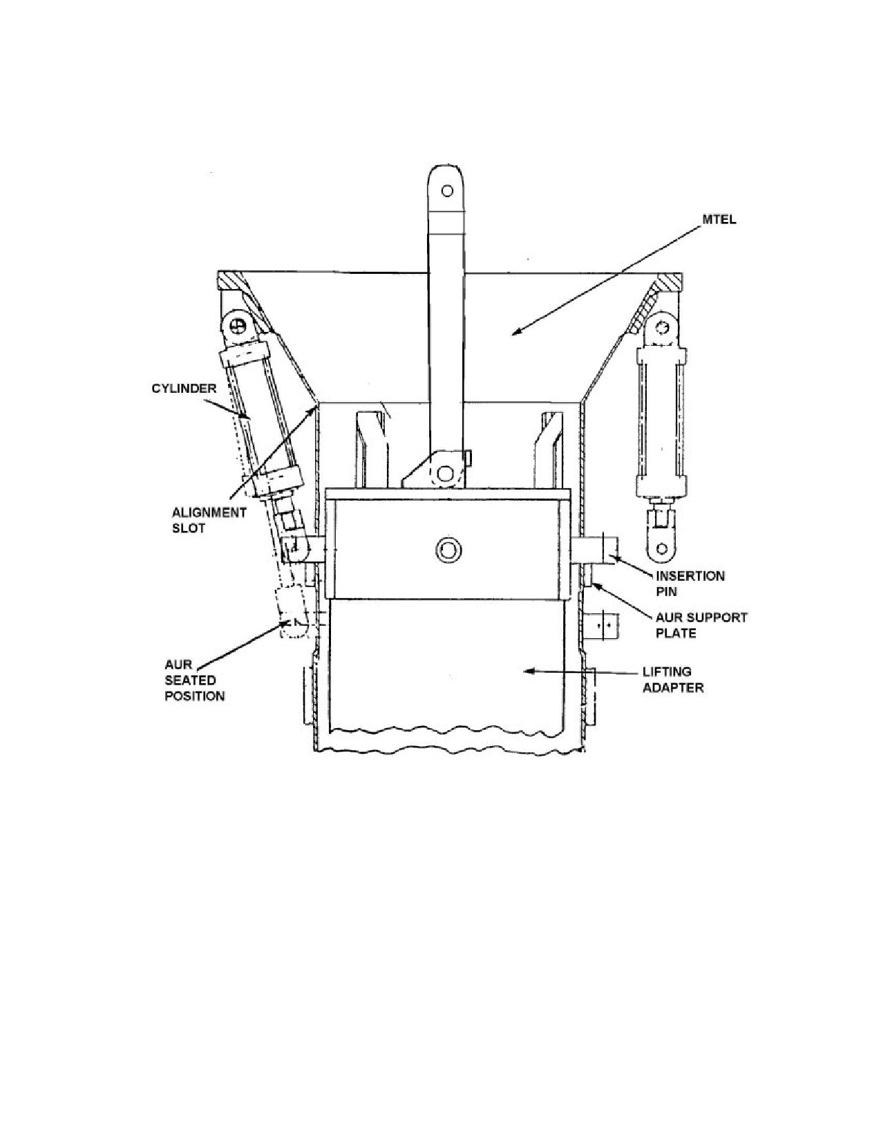
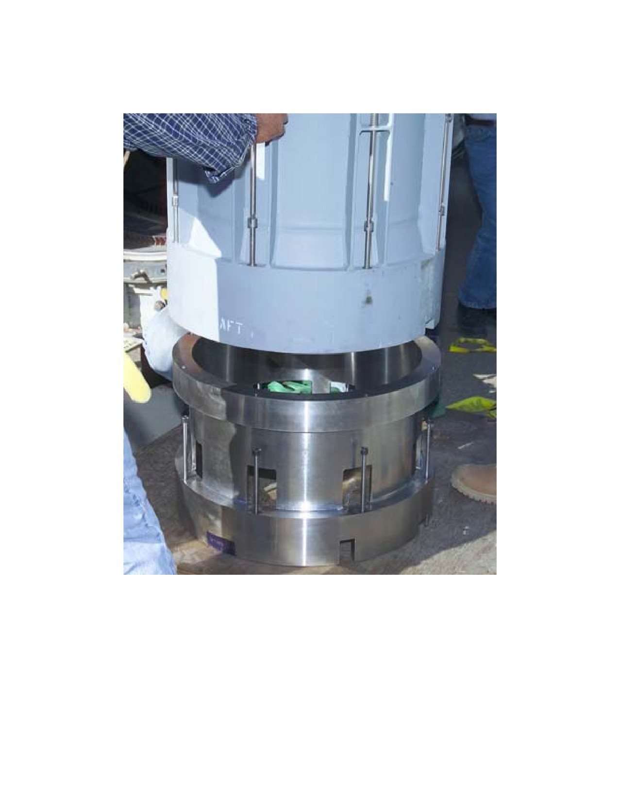
Figure 4-21. Lifting Adapter and Extension
271

SW820-AP-MMI-010
REVISION 15
27 MARCH 2009
CHAPTER 4
Figure 4-22. Vertical Launching System Mk 41 Mod 0
272

SW820-AP-MMI-010
REVISION 15
27 MARCH 2009
CHAPTER 4
Figure 4-23. Vertical Launching System Mk 41 Mod 1
273

SW820-AP-MMI-010
REVISION 15
27 MARCH 2009
CHAPTER 4
Figure 4-24. Vertical Launching System Mk 41 Mod 2
274

SW820-AP-MMI-010
REVISION 15
27 MARCH 2009
CHAPTER 4
Figure 4-25. Launch Control Unit (LCU)
275

SW820-AP-MMI-010
REVISION 15
27 MARCH 2009
CHAPTER 4
Figure 4-26. Vertical Launching System Launcher
276

SW820-AP-MMI-010
REVISION 15
27 MARCH 2009
CHAPTER 4
Figure 4-27. Remote Launch Enable Panel (RLEP)
277

SW820-AP-MMI-010
REVISION 15
27 MARCH 2009
CHAPTER 4
Figure 4-28. Status Panel
278
SW820-AP-MMI-010
REVISION 15
27 MARCH 2009
CHAPTER 4
Figure 4-29. Mk 14 VLS Canister PHS&T Equipment
279

SW820-AP-MMI-010
REVISION 15
27 MARCH 2009
CHAPTER 4
Figure 4-30. Secure Canister to Mk 23 Tilt Fixture
280
SW820-AP-MMI-010
REVISION 15
27 MARCH 2009
CHAPTER 4
Figure 4-31. Upright Mk 14 VLS Canister to Vertical
Position
281

SW820-AP-MMI-010
REVISION 15
27 MARCH 2009
CHAPTER 4
Figure 4-32. RGM-109-4 Land-Attack TCM
Operational Sequence (15 Sheets)
282
SW820-AP-MMI-010
REVISION 15
27 MARCH 2009
CHAPTER 4
283

SW820-AP-MMI-010
REVISION 15
27 MARCH 2009
CHAPTER 4
284

SW820-AP-MMI-010
REVISION 15
27 MARCH 2009
CHAPTER 4
285

SW820-AP-MMI-010
REVISION 15
27 MARCH 2009
CHAPTER 4
286
SW820-AP-MMI-010
REVISION 15
27 MARCH 2009
CHAPTER 4
287

SW820-AP-MMI-010
REVISION 15
27 MARCH 2009
CHAPTER 4
288

SW820-AP-MMI-010
REVISION 15
27 MARCH 2009
CHAPTER 4
289

SW820-AP-MMI-010
REVISION 15
27 MARCH 2009
CHAPTER 4
290
SW820-AP-MMI-010
REVISION 15
27 MARCH 2009
CHAPTER 4
291
SW820-AP-MMI-010
REVISION 15
27 MARCH 2009
CHAPTER 4
292

SW820-AP-MMI-010
REVISION 15
27 MARCH 2009
CHAPTER 4
293

SW820-AP-MMI-010
REVISION 15
27 MARCH 2009
CHAPTER 4
294

SW820-AP-MMI-010
REVISION 15
27 MARCH 2009
CHAPTER 4
295

SW820-AP-MMI-010
REVISION 15
27 MARCH 2009
CHAPTER 4
296
SW820-AP-MMI-010
REVISION 15
27 MARCH 2009
CHAPTER 4
Figure 4-33. Multiple All-Up-Round Canister (Fully
Loaded)
297
SW820-AP-MMI-010
REVISION 15
27 MARCH 2009
CHAPTER 4
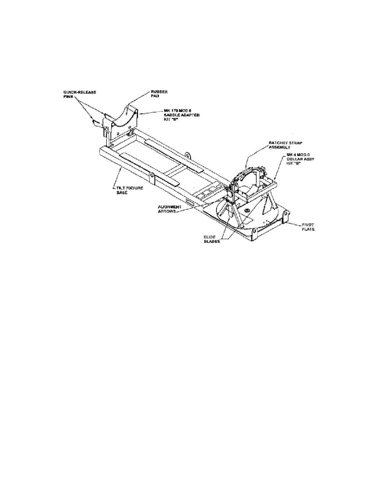
Figure 4-34. Tilt Fixture Mk 23 Mod 0 with Kit B
298

SW820-AP-MMI-010
REVISION 15
27 MARCH 2009
CHAPTER 4
Figure 4-35. Multiple All-Up-Round Canister MTEL
Orientation
299

SW820-AP-MMI-010
REVISION 15
27 MARCH 2009
CHAPTER 4
Figure 4-36. AUR Aft Cover Viewed in MAC
300
SW820-AP-MMI-010
REVISION 15
27 MARCH 2009
CHAPTER 4
Table 4-1. Missile Availability Factors
AVAILABILITY FACTOR
OVERRIDE
Failure in cell
Yes
Number of firings from cell exceeds eight (w/o
Yes
ORDALT 16235)
Number of firing counts from cell is/will be
Yes
10.75 or greater (w/ ORDALT 16235)
Missile in cooldown
Yes
Missile fuel leak
Yes
Module hazard/fault
Yes
Module BITE faults
Yes
Launch-sequence detected fault
Yes
Launcher unauthorized by TWCS
No
Canister or plenum cover not present/not
No
dogged down
Module declared unavailable
No
Restrained missile firing within module
No
MCP BITE is on but should not be
No
Module set to an offline status
No
No missile in cell
No
Cell and missile already selected for a
No
launching
Fault previously reported in half module
No
containing the missile
Fault previously reported in missile
No
Launch sequence failure previously reported
No
Launch operations not enabled in VLS
No
Cell-select relay (K1) not energized
No
301