Military reference books and manuals (2009-2023, Volume 5) - page 19
CJCSM 3212.02C
20 March 2011
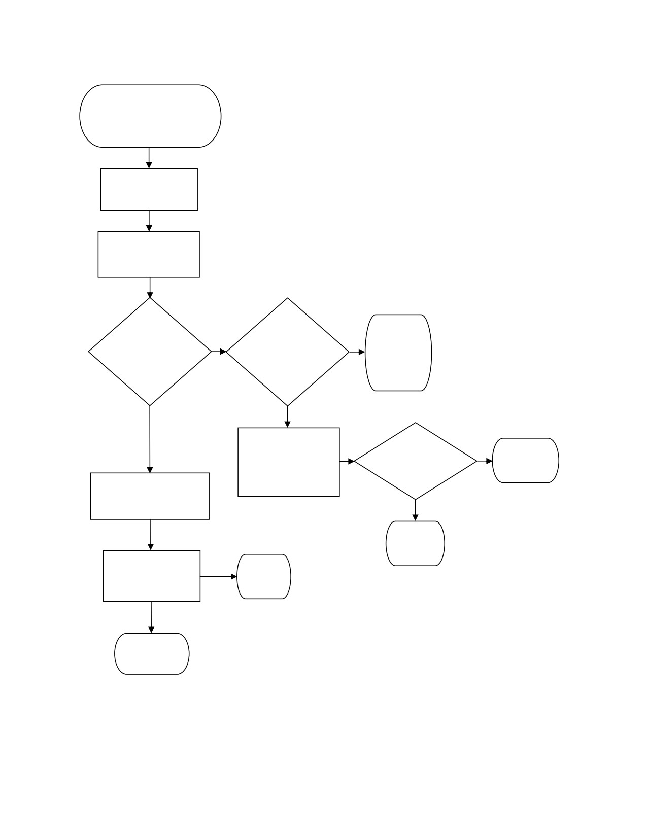
Coordination other than
DOD AFC or FACSFAC
User coordinates
w/Service POC
Service POC
validates request
No
No
No
National
Require local
coordination
FCC or other
approval
required?
coordination?
required
End
Yes
Yes
User/Service POC
Yes
coordinates with
Local
Approved
local FCC or
Approval?
End
specified agency
Service POC submits
(Note 1)
EA request to MILDEP
FMO
No
Denied
End
MILDEP FMO
Denied
coordinates EA
End
request
Approved
End
Note 1: FCC Watch Officer 202-418-1122
Figure 5. Coordination other than DOD AFC or FACSFAC
E-5
Enclosure E
CJCSM 3212.02C
20 March 2011
(INTENTIONALLY BLANK)
E-6
Enclosure E
CJCSM 3212.02C
20 March 2011
ENCLOSURE F
OPSEC CONSIDERATIONS
OPSEC advisories are transmitted as messages from Service agencies (for
example: USAF, AFSIRA, AFIOC). These advisories must be consulted, and
Services must ensure a collection threat does not exist during times of EA
transmissions of a classified nature. OPSEC considerations must be applied to
EW tests, exercises, and training activities to minimize the disclosure of
friendly capabilities while allowing for an effective training program across the
spectrum of EW operations.
F-1
Enclosure F
CJCSM 3212.02C
20 March 2011
(INTENTIONALLY BLANK)
F-2
Enclosure F
CJCSM 3212.02C
20 March 2011
ENCLOSURE G
EA FREQUENCY CLEARANCE NOTIFICATION
1. Office Responsible for EA Clearance Notification. EA frequency clearance
approval notification will be issued by the MILDEP FMO not later than (NLT) 10
working days prior to the proposed start date.
2. Contents of EA Approval Clearance Notification. Approval notification will
contain the following information:
a. Action Addressees. Service frequency coordinator and controlling
agency that initiated request.
b. Subject.
“EA Clearance Notification for National Frequencies.”
c. Reference. EA clearance request control number.
d. Initiation and Expiration Dates
e. Area of Operation. Name of range, MOA, restricted area, warning area
and coordinates and approved altitudes for airborne operations.
f. Hours. Weekly or daily operating hours, EA start/stop times (in UTC
and local) and duration of EA in hours.
g. Frequencies Approved
(1) Buzzer. Bands, channels, or specific frequencies approved for
jamming with BWs will be listed. Frequencies denied may be listed as well.
(2) Chaff. For burst or stream, frequency bands affected will be
indicated.
“NONE” will be indicated, if denied.
h. Remarks. Information on restrictions, distribution, and special
procedures will be placed here. Include statement “CEASE BUZZER
procedures will be in effect.” List EA mission POC, telephone (DSN and
commercial), and organization. If clearance approval notification does not
provide specific dates and times, include the statement, “Note: EA notification
message will be sent by operating unit to addressees as above, NLT 10 working
days prior to EA operations. Reference this clearance approval notification,
and state date and time EA will be conducted.”
G-1
Enclosure G
CJCSM 3212.02C
20 March 2011
3. In-Flight EA Notification
a. ARTCC, NORAD, and Range Controller Notification. Clearance requests,
which have been approved at the national level, allow EW users to conduct air,
land, or sea-based operations within the CONUS. Direct in-flight notification of
EA activity to ARTCC, NORAD, and/or the range controller, which have
jurisdiction over the areas where operations have been approved, is mandatory.
No additional in-flight clearance requests for EA outside the planned training
scenario should be attempted. Only EA activity previously approved may be
conducted. The previously approved EA activity will be indicated on the flight
plan (DD Form 175). The Cheyenne Mountain Operations Center (CMOC),
Command Director (CD), as CDR NORAD/CDR USNORTHCOM representative,
is authorized to direct the termination of any EA activity adversely affecting the
ability to carry out the mission of the surveillance of air and space against an
attack on North America. Additionally, agencies (air space managers and DOD
AFC offices) having jurisdiction over airspace involved in EW activity can deny
EW activity for safety-of-flight considerations or scheduling conflicts.
(1) Notification Information. Notify FAA, NORAD, and/or range
controllers (as appropriate) of the following flight information to confirm EW
activity:
(a) Aircraft call sign and flight level.
(b) FAA approval number (EW request number, e.g., 1ECRG90-4).
(c) Type of EW (electronic jamming “buzzer” or EA expendables
(burst or stream chaff, active decoys, unattended jammers)).
(d) Frequency bands and channels affected (see Enclosure I for
band designations).
(e) Location and duration of EW activity. NOTE: Chaff fall rate and
wind factors are used to determine area of burst or stream activity.
(2) Frequency Band Designators. All references to RF bands for EA
clearance purposes will use numeric designations in MHz. For example,
“Center, buzzer three one two five megahertz through three three zero zero
megahertz.” The entire list and a cross-reference graph to former designators
are in Enclosure I.
(3) Notification of the EA activity must be relayed to the NORAD
region/sector having jurisdiction over the involved airspace. EA activity will be
coordinated with the applicable ARTCC. In CONUS when NORAD is not within
radio range, aircrews must contact the ARTCC and request they notify NORAD
G-2
Enclosure G
CJCSM 3212.02C
20 March 2011
of EA activity. In-flight EA notification must be accomplished at least 10
minutes before desired EA start time.
(4) In Canada, aircrews are to contact the Mission Crew Commander,
North Bay, at telephone numbers (DSN) 319-628-6401(6402, 6404, or 6405) or
commercial 705-494-6011, then local 6401 (6402, 6404, or 6405).
(5) Previously approved burst chaff drops will only be accomplished
after final approval is received immediately preceding the drop, from the
ARTCC, NORAD, and/or range controller having jurisdiction over the airspace.
(6) If approved EA activity is denied, the reason for denial will be given
and treated as a CEASE BUZZER. Document appropriate information for
reference.
b. NORAD Notification Procedures. For pre-approved EW clearance
requests, if activity, will affect national frequencies within bands D-3, D-4, E-8,
E-9, G-6, I-3, I-4, I-5, I-6, I-7, I-8, K-2, or K-3 (see Enclosure I); or if activity
will affect FAA or NORAD joint-surveillance radars, NORAD will notify the
applicable AFC when EW operations may impact operations in an EW
geographic area of cognizance (see Enclosure M).
4. Clearance Notification. After validating the EA clearance notification
received from the MILDEP FMO, the Service frequency coordinator will provide
approval notification to the controlling agency making the request. The Service
frequency coordinator will also send the EA clearance notification to the
following as information addressees:
a. CDR USNORTHCOM//J3/J6/J653/J7/JFMO//.
b. CDR USJFCOM NORFOLK VA//J3/J6/J7// and JFMO LANT
NORFOLK VA (for training/exercises conducted under USJFCOM auspices).
c. Operating units as appropriate.
d. CMOC CHEYENNE MOUNTAIN AFS CO//J3/J35/AWC/MWC/SCC//.
e. DOD AFC (see Enclosure L).
f. HQ FAA Washington DC/ASR-100 if applicable.
g. FCC Washington DC/Frequency Liaison Branch, if applicable.
h. National Weather Service, as appropriate.
i. Appropriate FCC field operations office (see Enclosure J), if applicable.
G-3
Enclosure G
CJCSM 3212.02C
20 March 2011
j. Appropriate FAA ARTCC, if applicable.
k. FAA Regional FMO (see Enclosure K), if applicable.
l. For Canadian clearances, refer to Enclosure C, subparagraph 4d.
m. Appropriate NORAD regions/sectors that may be affected
n. HQ USAF WASHINGTON DC//AF/A5RE//, and additionally for space-
related operations:
AF/A3Z-SC, AF/A3Z-ST, AF/A3Z-SO.
o. COGARD NAVCEN ALEXANDRIA VA//NIS// (for maritime operations).
p. DISA JSC COMMCTR
q. NATIONAL TELECOMMUNICATIONS AND INFORMATION
ADMINISTRATION WASHINGTON DC.
r. AFFMA ALEXANDRIA VA//DOO//; (Note: AFFMA SIPRNET address is:
MLA-AFFMA-EW@affma.af.smil.mil).
s. GPS SUPPORT CENTER SCHRIEVER AFB CO.
t. NAVEMSCEN WASHINGTON DC//323//.
u. ARMY SPECTRUM MGT ALEXANDRIA VA//NETC-EST-V//.
G-4
Enclosure G
CJCSM 3212.02C
20 March 2011
ENCLOSURE H
CEASE BUZZER/CEASE MUSIC PROCEDURES
1. CEASE BUZZER/CEASE MUSIC Procedures. When suspension of EW
activity is required for safety-of-flight reasons, in cases of harmful interference
to authorized users of the RF spectrum, or for OPSEC reasons, the following
procedures will be used:
a. Communications Monitoring. During airborne EW, all EW aircraft must
monitor the emergency guard frequency (either 121.5 or 243.0 MHz)
continuously, in addition to the frequency designated for CEASE BUZZER
requests.
b. Safety of Flight. Authorized users of the spectrum requesting CEASE
BUZZER / CEASE MUSIC for safety-of-flight reasons will broadcast the request
directly to the EW originator on the frequency in use or on an emergency guard
frequency or will request CEASE BUZZER / CEASE MUSIC through the
controlling agency or AFC via ground to air radio. Everyone else must contact
Range Control or the AFC by phone for a CEASE BUZZER / CEASE MUSIC
order. EW originator will immediately cease the EW activity and notify the
requester of termination.
c. Other than Safety of Flight. Authorized users of the spectrum
requesting CEASE BUZZER / CEASE MUSIC for other than safety-of-flight
reasons will contact the appropriate controlling agency and provide
identification, type of facility, RF bands involved, and duration of suspension.
For example, “Boston Sector, this is Boston Center request CEASE BUZZER
2,200 megahertz through 2,300 megahertz for 5 minutes.” The controlling
agency will immediately pass the CEASE BUZZER request to the EW source
relaying the appropriate information. For example, “Bounder 31 this is Boston
Sector. CEASE BUZZER 2,200 megahertz through 2,300 megahertz for 5
minutes.”
d. Reinstatement of EW. Facilities requesting suspension of EW will notify
the controlling agency or EW originator when EW activity may be resumed.
e. Documentation. EW operators and controlling agencies, as appropriate,
will log all pertinent information regarding the CEASE BUZZER / CEASE
MUSIC request and compliance; i.e., time, RF bands, requester, time of
reinstatement and method by which request was received. Logs will be
retained in accordance with Service directives governing control logs.
H-1
Enclosure H
CJCSM 3212.02C
20 March 2011
(INTENTIONALLY BLANK)
H-2
Enclosure H
CJCSM 3212.02C
20 March 2011
ENCLOSURE I
EW FREQUENCY BAND DESIGNATIONS
1. Operational Band and Channel Codes. The bands and channels listed in
Table 3 are set up to give one standard system of frequency band designations
for EW operations and to facilitate the operational control of EW. The bands
are identified in alphabetical sequence. Each band is divided into 10
numerical channels. The phonetic alphabet and numerical channel numbers
are used to identify the EW frequency. During operations, when it becomes
necessary to identify an exact frequency, the frequency is specified as a
numerical designation (lowest frequency in any channel) plus frequency in MHz
above the base frequency. Example for 1315 MHz: DELTA 4 covers the
frequency range 1,300-1,400 MHz; 1,315 MHz would therefore be designated
DELTA 4 plus 15.
Band
Frequency (MHz)
Channel Width (MHz)
A(lpha)
0 - 250
25
B(ravo)
250 - 500
25
C(harlie)
500 - 1,000
50
D(elta)
1,000 - 2,000
100
E(cho)
2,000 - 3,000
100
F(oxtrot)
3,000 - 4,000
100
G(olf)
4,000 - 6,000
200
H(otel)
6,000 - 8,000
200
I(ndia)
8,000 - 10,000
200
J(uliet)
10,000 - 20,000
1,000
K(ilo)
20,000 - 40,000
2,000
L(ima)
40,000 - 60,000
2,000
M(ike)
60,000 - 100,000
4,000
N(ovember)
100,000 - 200,000
10,000
O(scar)
200,000 - 300,000
10,000
Table 3. EW Frequency Band Designations
I-1
Enclosure I
CJCSM 3212.02C
20 March 2011
2. EA Coordination Requirements by Frequency Band
a. Canada: All EA performed in Canada requires national coordination.
b. United States: Table 4 has been coordinated at the national level. The
status of the frequency bands for EW in the United States is annotated below
as “Local,” “Local (FCC),” or “National.” Each status is defined in the Glossary
of this manual and in the procedures in Enclosure C.
c. National Coordination: In Table 4, “National” coordination requires the
request be forwarded to the cognizant MILDEP FMO for coordination. The
frequency bands are listed consecutively to include all frequencies for ease of
understanding. Obviously, one frequency cannot be both national and local.
Therefore, the following rules apply. All frequency bands designated national
are inclusive. All “Local” or “Local (FCC)” frequencies adjacent to a national
frequency band begin or end at the first increment adjacent to the national
frequencies. Local (FCC) frequencies are inclusive when adjacent to a local
frequency. For example, in the band 25-50 MHz, all frequencies from 25 MHz
through 50 MHz require national coordination; frequencies 50.001 MHz
through 53.999 MHz require local coordination; and frequencies 54MHz
through 72.999 MHz require local (FCC) coordination. NOTE: The reallocation
of federal RF spectrum is an ongoing process. Reallocation may affect testing
in some of the spectrum bands listed in Table 4. The MILDEP FMOs have the
latest information on spectrum reallocation actions and will factor this
knowledge into the national coordination process.
Channel
(MHz)
United States
A-1
0-25
National
A-2
25-50
National
A-3
50-75.2
[50-54
Local
54-73
Local (FCC)
73-75.2]
National1
A-4
75.2-100
[75.2-75.4
National
75.4-100]
Local (FCC)
A-5
100-125
[100-108
Local (FCC)
108-125]
National1
A-6
125-150
[125-138
National1
138-150]
Local
Table 4 Coordination Level Required by Channel and Frequency
I-2
Enclosure I
CJCSM 3212.02C
20 March 2011
Channel
(MHz)
United States
A-7
150-175
[150-156
Local
156-158
National
158-161
Local
161-174
National
174-175]
Local (FCC)
A-8
175-200
Local (FCC)
A-9
200-225
[200-216
Local (FCC)
216-222
National
222-225]
Local
A-10
225-250
[225-242.5
National1
242.5-243.5
National (Guard
Frequency)1
243.5-250]
National1
B-1
250-275
National1
B-2
275-300
National1
B-3
300-325
National1
B-4
325-350
National1
B-5
350-375
National1
B-6
375-400
National1
B-7
400-425
[400-420
National
420-425]
Local
B-8
425-450
[425-448
Local
448-450]
National
B-9
450-475
National
B-10
475-500
National
C-1
500-550
[500-512
National1
512-550]
Local (FCC)
Table 4 Coordination Level Required by Channel and Frequency (Continued)
I-1
Enclosure I
CJCSM 3212.02C
20 March 2011
Channel
(MHz)
United States
C-2
550-600
Local (FCC)
C-3
600-650
[600-608
Local (FCC)
608-614
National
614-650]
Local (FCC)
C-4
650-700
Local (FCC)
C-5
700-750
Local (FCC)
C-6
750-800
Local (FCC)
C-7
800-850
[800-806
Local (FCC)
806-850]
National
C-8
850-900
National
C-9
900-950
[900-902
National
902-928
Local
928-950]
National1
C-10
950-1,000
[950-960
National
960-1000]
National1
D-1
1,000-1,100
National1
D-2
1,100-1,200
National1
D-3
1,200-1,300
National1
D-4
1,300-1,400
[1,300-1,390
National1
1,390-1,400]
National
D-5
1,400-1,500
National1
D-6
1,500-1,600
National1
D-7
1,600-1,700
National1
D-8
1,700-1,800
National
D-9
1,800-1,900
National
D-10
1,900-2,000
National
Table 4 Coordination Level Required by Channel and Frequency (Continued)
I-1
Enclosure I
CJCSM 3212.02C
20 March 2011
Channel
(MHz)
United States
E-1
2,000-2,100
National
E-2
2,100-2,200
National
E-3
2,200-2,300
National
E-4
2,300-2,400
[2,300-2,305
Local
2,305-2,390
National
2,390-2,400]
Local
E-5
2,400-2,500
[2,400-2,483.5
Local
2,483.5-2,500]
National
E-6
2,500-2,600
National
E-7
2,600-2,700
National
E-8
2,700-2,800
National1
E-9
2,800-2,900
National1
E-10
2,900-3,000
National
F-1
3,000-3,100
National
F-2
3,100-3,200
Local
F-3
3,200-3,300
Local
F-4
3,300-3,400
Local
F-5
3,400-3,500
Local
F-6
3,500-3,600
Local
F-7
3,600-3,700
[3,600-3,650
Local
3,650-3,700]
National
F-8
3,700-3,800
National
F-9
3,800-3,900
National
F-10
3,900-4,000
National
G-1
4,000-4,200
National
Table 4 Coordination Level Required by Channel and Frequency (Continued)
I-1
Enclosure I
CJCSM 3212.02C
20 March 2011
Channel
(MHz)
United States
G-2
4,200-4,400
National1
G-3
4,400-4,600
Local
G-4
4,600-4,800
[4,600-4,635
Local
4,635-4,685
National
4,685-4,800]
Local
G-5
4,800-5,000
[4,800-4,990
Local
4,990-5,000]
National
G-6
5,000-5,200
National1
G-7
5,200-5,400
[5,200-5,250
National1
5,250-5,400]
Local
G-8
5,400-5,600
Local
G-9
5,600-5,800
[5,600-5,650
National1
5,650-5,800]
Local
G-10
5,800-6,000
[5,800-5,850
Local
5,850-6,000]
National
H-1
6,000-6,200
National
H-2
6,200-6,400
National
H-3
6,400-6,600
National
H-4
6,600-6,800
National
H-5
6,800-7,000
National
H-6
7,000-7,200
National
H-7
7,200-7,400
National
H-8
7,400-7,600
National
H-9
7,600-7,800
National
H-10
7,800-8,000
National
Table 4 Coordination Level Required by Channel and Frequency (Continued)
I-1
Enclosure I
CJCSM 3212.02C
20 March 2011
Channel
(MHz)
United States
I-1
8,000-8,200
National
I-2
8,200-8,400
National
I-3
8,400-8,600
[8,400-8,500
National
8,500-8,600]
Local
I-4
8,600-8,800
Local
I-5
8,800-9,000
Local
I-6
9,000-9,200
National1
I-7
9,200-9,400
[9,200-9,300
Local
9,300-9,400]
National
I-8
9,400-9,600
[9,400-9,500
National
9,500-9,600]
Local
I-9
9,600-9,800
Local
I-10
9,800-10,000
Local
J-1
10,000-11,000
[10,000-10,550
Local
10,550-11,000]
National
J-2
11,000-12,000
[11,000-11,700
National
11,700-12,000]
Local (FCC)
J-3
12,000-13,000
Local (FCC)
J-4
13,000-14,000
[13,000-13,250
Local (FCC)
13,250-14,000]
Local2
J-5
14,000-15,000
National
J-6
15,000-16,000
National1
J-7
16,000-17,000
National1
J-8
17,000-18,000
[17,000-17,700
National1
17,700-18,000]
Local (FCC)
Table 4 Coordination Level Required by Channel and Frequency (Continued)
I-1
Enclosure I
CJCSM 3212.02C
20 March 2011
Channel
(MHz)
United States
J-9
18,000-19,000
Local (FCC)
J-10
19,000-20,000
[19,000-19,700
Local (FCC)
19,700-20,000]
National
K-1
20,000-22,000
National
K-2
22,000-24,000
National
K-3
24,000-26,000
[24,000-24,050
Local
24,050-26,000]
National
K-4
26,000-28,000
[26,000-27,500
Local
27,500-28,000]
National
K-5
28,000-30,000
National
K-6
30,000-32,000
[30,000-31,300
Local (FCC)
31,300-31,800
National
31,800-32,000]
Local
K-7
32,000-34,000
Local
K-8
34,000-36,000
Local
K-9
36,000-38,000
National
K-10
38,000-40,000
National
L-1
40,000-42,000
National
L-2
42,000-44,000
[42,000-42,500
National
42,500-44,000]
Local
L-3
44,000-46,000
[44,000-44,500
Local
44,500-46,000]
National
L-4
46,000-48,000
National
L-5
48,000-50,000
National
Table 4 Coordination Level Required by Channel and Frequency (Continued)
I-1
Enclosure I
CJCSM 3212.02C
20 March 2011
Channel
(MHz)
United States
L-6
50,000-52,000
[50,000-51,400
Local
51,400-52,000]
National
L-7
52,000-54,000
National
L-8
54,000-56,000
National
L-9
56,000-58,000)
National
L-10
58,000-60,000
National
M-1
60,000-64,000
Local
M-2
64,000-68,000
Local
M-3
68,000-72,000
Local
M-4
72,000-76,000
Local
M-5
76,000-80,000
[76,000-77,000
National
77,000-80,000]
Local
M-6
80,000-84,000
Local
M-7
84,000-88,000
[84,000-86,000
Local
86,000-88,000]
National
M-8
88,000-92,000
National
M-9
92,000-96,000
Local
M-10
96,000-100,000
Local
N-1
100,000-110,000
[100,000-100,200
Local
100,200-102,000
National
102,000-105,000
Local
105,000-110,000]
National
N-2
110,000-120,000
[110,000-116,000
National
116,000-120,000]
Local
N-3
120,000-130,000
Local
Table 4 Coordination Level Required by Channel and Frequency (Continued)
I-1
Enclosure I
CJCSM 3212.02C
20 March 2011
Channel
(MHz)
United States
N-4
130,000-140,000
Local
N-5
140,000-150,000
Local
N-6
150,000-160,000
Local
N-7
160,000-170,000
[160,000-164,000
Local
164,000-168,000
National
168,000-170,000]
Local
N-8
170,000-180,000
Local
N-9
180,000-190,000
[180,000-182,000
Local
182,000-185,000
National
185,000-190,000]
Local
N-10
190,000-200,000
Local
O-1
200,000-210,000
Local
O-2
210,000-220,000
[210,000-217,000
Local
217,000-220,000]
National
O-3
220,000-230,000
Local
O-4
230,000-240,000
[230,000-231,000
National
231,000-240,000]
Local
O-5
240,000-250,000
Local
O-6
250,000-260,000
[250,000-252,000
National
252,000-260,000]
Local
O-7
260,000-270,000
Local
O-8
270,000-280,000
Local
O-9
280,000-290,000
Local
O-10
290,000-300,000
Local
Table 4. Coordination Level Required by Channel and Frequency
1 FAA coordination required.
2 Except that national coordination is required for the 13,750-14,000 MHz frequency band
within 200 nm of the NASA site at Las Cruces, NM.
I-1
Enclosure I
CJCSM 3212.02C
20 March 2011
ENCLOSURE J
FCC FIELD OFFICES
NOTE: Local FCC offices and phone numbers are not listed. All local
coordination is conducted through the FCC watch officer at (202) 418-1122.
The watch officer will provide the appropriate local POC. EA notifications
should also be faxed to the FCC watch officer at (202) 418-0908.
J-1
Enclosure J
CJCSM 3212.02C
20 March 2011
(INTENTIONALLY BLANK)
J-2
Enclosure J
CJCSM 3212.02C
20 March 2011
ENCLOSURE K
FAA REGIONAL OFFICES AND AREAS OF RESPONSIBILITY
Region
Address
Area of
Responsibility
Head-
Federal Aviation Administration
quarters
Spectrum Policy and Management,
ASR-100
800 Independence Avenue, SW
Washington, D.C. 20591
Phone: 202-267-9710
MSG ADD: FAA NATIONAL HQ
WASHINGTON DC//ASR-100//
Alaskan
Federal Aviation Administration
Alaska
Spectrum Management Office, AAL-470
222 West 7th Avenue, P.O. Box 14
Anchorage, AK 99513-7987
Phone: 907-271-5800/2238
MSG ADD: FAA ALASKAN RGN HQ
ANCHORAGE AK//AAL-470/AAL-530//
Central
Federal Aviation Administration
Iowa, Kansas,
Spectrum Management Office, ACE-474
Missouri, and
901 Locust ATTN: ACE 474
Nebraska
Kansas City, MO 64106
Phone: 816-329-3466/3467
MSG ADD: FAA CENTRAL RGN HQ
KANSAS CITY MO//ACE-474/ACE-530//
Eastern
Federal Aviation Administration
Delaware, D.C.,
Spectrum Management Office, AEW-472
Maryland, New
One Aviation Plaza
Jersey, New York,
Jamaica, NY 11434-4809
Pennsylvania,
Phone: 718-977-6608
Virginia, and West
MSG ADD: FAA EASTERN RGN HQ
Virginia
JAMAICA NY//AEA-483/AEA-530//
K-1
Enclosure K
CJCSM 3212.02C
20 March 2011
Region
Address
Area of
Responsibility
Great
Federal Aviation Administration
Illinois, Indiana,
Lakes
Spectrum Management Office, AGL-474B
Michigan,
2300 E. Devon Ave.
Minnesota, North
Des Plaines, IL 60018
Dakota, South
Phone: 847-294-8471
Dakota, Ohio, and
MSG ADD: FAA GREAT LAKES RGN HQ
Wisconsin
DES PLAINES IL//AGL-474B/AGL-530//
Hawaiian-
Federal Aviation Administration
Hawaii and U.S.
Pacific
Spectrum Management Office, AWP-476
possessions in the
300 Ala Moana Blvd Rm 7-128
Pacific Ocean
Honolulu, HI 96813
Phone: 808-541-1241
MSG ADD: FAA HONOLULU CERAP
HONOLULU HI//AWP-476//
New
Federal Aviation Administration
Connecticut,
England
Spectrum Management Office, ANE-471
Maine, Vermont,
12 New England Executive Park
Massachusetts,
Burlington, MA 01803
New Hampshire,
Phone: 781-238-7490
and Rhode Island
MSG ADD: FAA NEW ENGLAND RGN HQ
BURLINGTON MA//ANE-471/ANE-530//
Northwest
Federal Aviation Administration
Colorado, Idaho,
Mountain
Spectrum Management Office, ANM-473
Montana, Oregon,
1601 Lind Ave. SW
Utah, Washington,
Renton, WA 98055-4056
and Wyoming
Phone: 206-227-2328
MSG ADD: FAA NORTHWEST MOUNTAIN
RGN HQ SEATTLE WA//ANM-473/ANM-
530//
Southern
Federal Aviation Administration
Alabama, Florida,
Spectrum Management Office, ASO-473
Kentucky,
P.O. Box 20636
Mississippi, North
Atlanta, GA 30320
Carolina, Georgia,
Phone: 404-305-6672
South Carolina,
MSG ADD: FAA SOUTHERN RGN HQ
Tennessee, U.S.
ATLANTA GA//ASO-483/ASO-530//
possessions in the
Caribbean, Virgin
Islands
K-2
Enclosure K
CJCSM 3212.02C
20 March 2011
Region
Address
Area of
Responsibility
Southwest
Federal Aviation Administration
Arkansas, New
Spectrum Management Office, ASW-473
Mexico,
2601 Meacham Blvd.
Oklahoma, Texas,
Fort Worth, TX 76193-0473
and Louisiana
Phone: 817-222-4762
MSG ADD: FAA SOUTHWEST RGN HQ FT
WORTH TX//ASW-473/ASW-530//
Western
Federal Aviation Administration
Arizona,
Pacific
Spectrum Management Office, AWP-475
California,
P.O. Box 92007
including off-shore
Worldway Postal Center
islands, and
Los Angeles, CA 90009-2007
Nevada
Phone: 310-725-3475
MSG ADD: FAA WESTERN PACIFIC RGN
HQ LOS ANGELES CA//AWP-475/AWP-
530//
K-3
Enclosure K
CJCSM 3212.02C
20 March 2011
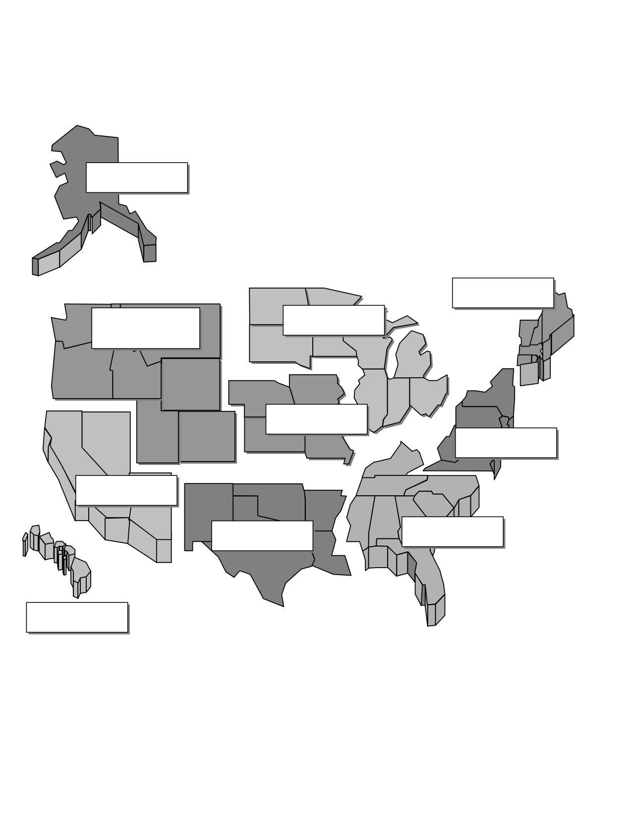
ALASKA
REGION
NEW ENGLAND
REGION
GREAT LAKES
NORTHWEST
MOUNTAIN
REGION
REGION
CENTRAL
REGION
EASTERN
REGION
WESTERN
PACIFIC REGION
SOUTHERN
SOUTHWEST
REGION
REGION
HAWAIIAN-
PACIFIC REGION
Figure 6. FAA Region Map
K-4
Enclosure K
CJCSM 3212.02C
20 March 2011
ENCLOSURE L
GEOGRAPHIC AREA OF COGNIZANCE/AGENCIES, DOD AREA FREQUENCY
COORDINATORS
1. EA Geographic Area of Cognizance. EW is strictly controlled within
geographic areas in accordance with Joint Staff directives governing test and
exercise ranges. Clearance to operate in these areas must be granted by the
appropriate area frequency coordinator in addition to the coordination
requirements of Enclosure C.
2. DOD Geographic Area of Cognizance and AFCs
Geographic Area
Controlling Agency
Alaska, including the Aleutian Area Frequency Coordinator
Island Chain.
JFMO AK
9480 Pease Avenue, Suite 310
Elmendorf AFB, AK 99506-2100
DSN: 317-552-8223/7183
MSG ADD: RUHHHGA/ALCOM
ELMENDORF AFB AK//J6//
Arizona
Area Frequency Coordinator
ATTN: SFIS-FAC-SH
Ft Huachuca, AZ 85613-5000
Tel:
602-538-6423
DSN: 879-6423
MSG ADD: DOD AFC AZ FT
HUACHUCA AZ//SFIS-FAC-SH//
Colorado, west of 108oW; New
Area Frequency Coordinator
Mexico; Utah, east of 111o;
White Sands Missile Range,
and Texas, west of 104oW.
NM 88002-5526
Tel:
505-678-5417
DSN: 258-5417
MSG ADD: DOD AFC WHITE SANDS
MISSILE RANGE NM//SFIS-FAC-SS//
L-1
Enclosure L
CJCSM 3212.02C
20 March 2011
Geographic Area
Controlling Agency
Florida, east of 83oW; and
Eastern Area Frequency Coordinator
Georgia, east of 83oW and
Patrick AFB, FL 32925-6345
south of 31o30' N.
Tel:
321-494-5837
DSN: 854-5837/5838
MSG ADD: DOD EAFC PATRICK AFB
FL
Puerto Rico, 200 nm radius of
DOD Area Frequency Coordinator
18o 15'N, 65o 38'W (AFWTF,
Puerto Rico
Puerto Rico)
CODE 096
PSC 1008, Box 3023
FPO AA 34051-9000
Tel: 809-865-5227/7001
DSN: 831-5227
MSG ADD: DOD AFC PR ROOSEVELT
ROADS PR
California, south of 37o30'N,
Western Area Frequency Coordinator
including all off-shore islands
Code 521700E
575 I Ave., Suite 1
Point Mugu, CA 93042-5049
Tel:
805-989-7983
DSN: 351-7983/7981
MSG ADD: WAFC PT MUGU CA
Alabama, south of 33o30'N;
Gulf Area Frequency Coordinator
Florida, west of 83oW; Georgia,
201 W. Eglin Boulevard, Suite 206,
west of 83oW and south of
Eglin AFB, FL 32542-6829
33o30'N; Louisiana, east of
Tel:
904-882-4416
90oW; and Mississippi, east of
DSN: 872-4416
90oW and south of 33o30'N.
MSG ADD: DOD GAFC EGLIN AFB FL
L-2
Enclosure L
CJCSM 3212.02C
20 March 2011
Geographic Area
Controlling Agency
Nevada; Utah, west of 111oW;
DOD Area Frequency Coordinator
and Idaho, south of 44oN.
Nellis AFB, NV 89191
Tel:
702-652-3417
DSN: 682-3417
MSG ADD: DOD AFC NELLIS AFB NV
Hawaiian Islands and Guam,
Area Frequency Coordinator,
200 nm radius outward from
JFMO PAC
the center of each island.
USPACOM J613, Box 64029 Camp H.
Oahu - 2127’34’’N,
M. Smith, HI 96861-4029
15759’54’’W,
Tel:
808-477-1051/50
DSN: 315-477-1051/50
Kauai - 2202’28’’N,
AUTODIN MSG ADD: JFMO PAC
15929’03’’W Maui -
HONOLULU HI//J613//
2042’59’’N, 15615’43’’W
DMS ADD: JFMOPAC (SC)
Hawaii - 1940’03’’N,
AUTODIN MSG ADD: JFMO GUAM
15530’14’’W. Guam -
ISLAND GU//J613//
1333’54’’N, 14453’45’’E.
DMS ADD: JFMO GUAM ISLAND GU
(SC)
Kwajalein Atoll, 200 nm radius
DOD Area Frequency Coordinator
outward from 0843’07’’N,
Kwajalein
16743’52’’E.
U.S. ARMY KWAJALEIN
ATOLL\REAGAN TEST SITE (RTS)
PO Box 1706
APO AP 96555
Tel:
805-335-2953
DSN: 315-254-2953
AUTODIN MSG ADD: DOD AFC
KWAJALEIN MH
DMS ADD: KWAJALEIN USAKA DOD
AFC
L-3
Enclosure L
CJCSM 3212.02C
20 March 2011
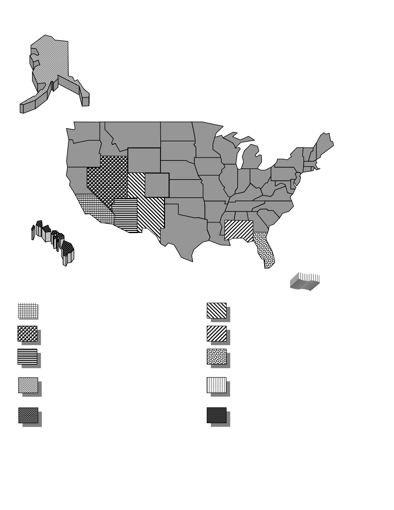
DOD AFC WHITE SANDS
DOD AFC WESTERN AREA (WAFC)
MISSILE RANGE (WSMR)
DOD AFC GULF AREA
DOD AFC NELLIS
(GAFC)
DOD AFC EASTERN AREA
DOD AFC FT HUACHUCA
(EAFC)
JFMO ALASKA
DOD AFC PUERTO RICO
JFMO PACIFIC
DOD AFC Kwajalein Atoll
(Guam not depicted)
(not depicted)
Figure 7. Map of Geographic Areas
L-4
Enclosure L
CJCSM 3212.02C
20 March 2011
ENCLOSURE M
NORAD EA COORDINATION ADDRESSES
NORAD Regions/Sectors Message Address
Alaskan NORAD Region ANR ELMENDORF AFB AK//DO/DOC//
(ANR)
Canadian NORAD Region
1 CAD/CANR//DCR/A3//
(CANR)
CONUS NORAD Region CONR TYNDALL AFB FL//DO/DOC//
(CONR)
Eastern Air Defense
EAST AIR DEFENSE SECTOR ROME
Sector (EADS)
NY//DO/DOC//
Western Air Defense
WESTERN AIR DEFENSE SECTOR
Sector (WADS)
MCCHORD AFB WA//DO/DOC//
M-1
Enclosure M

CJCSM 3212.02C
20 March 2011
ANR
CANR
WADS
CONR
EADS
Figure 8. Map of NORAD Regions and Sectors
M-2
Enclosure M
CJCSM 3212.02C
20 March 2011
ENCLOSURE N
REFERENCES
a. Communications Act of 1934, Pub. L. No. 416, ch. 652; 48 Stat. 1064,
(1934); Chapter 5 47 U.S.C. § 151 et seq; as amended by the
Telecommunications Act of 1996
b. CJCSI 3210.03 Series, “Joint EW Policy”
c.
“CJCS Directives Electronic Library,” Information Management Division,
21 December 2010, <http://www.dtic.mil/cjcs_directives> (accessed: January
5, 2010)
d. Federal Aviation Act of 1958, Pub. L. No. 85-726, 72 Stat. 731, (1958);
Chapter 1 49 U.S.C. § 106 et seq, as amended
e.
“International Telecommunication Union,” Radio Regulations,
<http://www.itu.int/publ/R-REG-RR/en> (accessed: January 18, 2010)
f. National Environmental Policy Act of 1969, Pub. L. No. 91-190, 83 Stat. 852
(1969); Chapter 55 42 U.S.C. § 4321 et seq.
g. Federal Aviation Administration Order JO 7610.4G, and 7610.11, and
Range Regulation MSD 55-3.
h. DODD 5200.1-R, 14 January 1997, (certified current as of 24 November
2003) “Information Security Program”
i. OPNAVINST S5513.8B-88, “JOINT COUNTER RADIO CONTROLLED
IMPROVISED EXPLOSIVE DEVICE ELECTRONIC WARFARE (CREW)
PROGRAM SECURITY CLASSIFICATION GUIDE,” Rev 1, 2 April 2007
SUPPORTING DOCUMENTS
DODD 3222.3, 4 September 2004 “Electromagnetic Environmental Effects
Program
N-1
Enclosure N
CJCSM 3212.02C
20 March 2011
(INTENTIONALLY BLANK)
N-2
Enclosure N
CJCSM 3212.02C
20 March 2011
GLOSSARY
PART I -- ABBREVIATIONS/ACRONYMS
ABBREVIATION
Phrase
ADIZ
Air Defense Identification Zone
AFB
Air Force Base
AFC
area frequency coordinator
AFFMA
Air Force Frequency Management Agency
AFIOC
Air Force Information Operations Center
AFWTF
Atlantic Fleet Weapons Training Facility
AGL
above ground level
ANR
Alaskan NORAD Region
AOR
area of responsibility
ARTCC
Air Route Traffic Control Center
ATC
air traffic control
BMW
Beamwidth
BW
Bandwidth
CANR
CONUS NORAD Region
CD
command director
CDR
Commander
CJCSI
Chairman of the Joint Chiefs of Staff instruction
CJCSM
Chairman of the Joint Chiefs of Staff manual
CMOC
Cheyenne Mountain Operations Center
COCOM
Combatant Commander
CONR
CONUS NORAD Region
CONUS
continental United States
CREW
Counter RCIED Electronic Warfare
dB
Decibel
dBm
decibels referenced to one milliwatt
DDGO
Deputy Director for Global Operations (Joint Staff
J3 deputy directorate)
DDIO
Deputy Director for Information Operations (Joint
Staff J3 deputy directorate)
DE
directed energy
DEW
directed energy warfare
DTSES 5
Director, Telecommunications and Spectrum
Engineering Support 5 (Canadian MILDEP
FMO)
DOD
Department of Defense
DOD AFC
Department of Defense area frequency coordinator
GL-1
Glossary
CJCSM 3212.02C
20 March 2011
ABBREVIATION
Phrase
DODD
Department of Defense directive
DMS
Defense Message System
DSN
Defense Switched Network
DOT
Department of Transportation
EA
electronic attack
EADS
Eastern Air Defense Sector
EAFC
eastern area frequency coordinator
ECM
electronic countermeasures
EMI
electromagnetic interference
EP
electronic protect
ES
electronic warfare support
EW
electronic warfare
FAA
Federal Aviation Administration
FACSFAC
fleet area coordination and surveillance facility
FCC
Federal Communications Commission
FMO
frequency management office
GHz
Gigahertz
GPS
global positioning system
GPSSC
GPS support center
HQ
Headquarters
IAW
in accordance with
ICAO
International Civil Aviation Organization
IRAC
Interdepartmental Radio Advisory Committee
ISM
Installation Spectrum Manager
ITU
International Telecommunications Union
JFCOM
Joint Forces Command
JFMO
Joint Frequency Management Office
JSC
Joint Spectrum Center
kHz
Kilohertz
LAT
Latitude
LONG
Longitude
LOS
line of sight
MHz
Megahertz
MILDEP
Military Department
MOA
Military Operating Area
MSL
mean sea level
GL-2
Glossary
CJCSM 3212.02C
20 March 2011
ABBREVIATION
Phrase
NAVCAN
A private, nonprofit agency responsible for the
management and operation of the Canadian
National Air Traffic Control System.
Transport Canada retains responsibility for
policy, etc.
NAVCEN
navigation center
NAVMARSPECCEN
Navy Marine Corps Spectrum Center
NDHQ
National Defence Headquarters (Canada)
NEPA
National Environmental Policy Act
NLT
not later than
nm
nautical miles
NORAD
North American Aerospace Defense Command
NTIA
National Telecommunications and Information
Administration
OPSEC
operations security
POC
point of contact
PWR
Power
RCIED
Radio-controlled improvised explosive device
RF
radio frequency
SOCAL
Southern California Operating Area
US&P
United States and Possessions
USA
U.S. Army
USAF
U.S. Air Force
USCENTCOM
United States Central Command
USJFCOM
United States Joint Forces Command
USMC
U.S. Marine Corps
USN
U.S. Navy
USNORTHCOM
United States Northern Command
USPACOM
United States Pacific Command
USSOCOM
United States Special Operations Command
USSOUTHCOM
United States Southern Command
USSTRATCOM
United States Strategic Command
UTC
Coordinated Universal Time
VACAPES
Virginia Capes Operating Area
VFR
visual flight rules
VHF
very high frequency
WADS
Western Air Defense Sector
GL-3
Glossary
CJCSM 3212.02C
20 March 2011
PART II -- DEFINITIONS1
Airborne EA. All types of electronic jamming, electronic deception, or the use
of EA expendables including chaff, flares, unmanned vehicles, decoys, and
unattended jammers dispensed by aircraft or other vehicles during flight.
Barrage Jamming. Simultaneous electromagnetic jamming over a broad band
of frequencies.
(Joint Pub 1-02)
Big Photo. A general call sign used to contact aircraft performing airborne EA.
Burst. Chaff dropped with a separation (time interval) great enough to appear
on a radarscope as individual target returns.
Buzzer. Electronic noise jamming or deception.
Canada. For purposes of this manual, Canada includes the 10 Provinces; the
Yukon; the Northwest and Nunavut; the Arctic Islands and surrounding
waters; the area extending to the outer boundaries of the Atlantic and Pacific
Canadian Air Defense Identification Zone (ADIZ); and the Northern Domestic
Airspace; or a perimeter 200 nm seaward from the coastal provinces and
territories, whichever is further out, except where this infringes on territorial
limits of other nations or states.
Cease Buzzer/Music. Unclassified term used to terminate EA activities,
including the use of EW expendables. CEASE BUZZER is used to cease
jamming communications and CEASE MUSIC refers to stopping radar
jamming.
Chaff. Radar confusion reflectors, consisting of thin, narrow metallic strips of
various lengths and frequency responses, which are used to reflect echoes for
confusion purposes. Causes enemy radar guided missiles to lock onto it
instead of the real aircraft, ship, or other platform.
(Joint Pub 1-02)
Directed Energy. Also called DE. An umbrella term covering technologies
relating to the production of a beam of concentrated electromagnetic energy or
atomic or subatomic particles. (Joint Pub 1-02)
Directed-Energy Warfare. Also called DEW. Military action involving the use
of directed-energy weapons, devices, and countermeasures to either cause
direct damage or destruction of enemy equipment, facilities, and personnel, or
to determine, exploit, reduce, or prevent hostile use of the EMS through
damage, destruction, and disruption. It also includes actions taken to protect
1 Used only in context with this manual unless otherwise denoted.
GL-4
Glossary
CJCSM 3212.02C
20 March 2011
friendly equipment, facilities, and personnel, and retain friendly use of the
EMS. (Joint Pub 1-02)
Directed-Energy Weapon. A system using directed energy primarily as a
direct means to damage or destroy enemy equipment, facilities, and personnel.
(Joint Pub 1-02)
Electromagnetic Deception. The deliberate radiation, re-radiation, alteration,
suppression, absorption, denial, enhancement, or reflection of electromagnetic
energy in a manner intended to convey misleading information to an enemy or
to enemy electromagnetic-dependent weapons, thereby degrading or
neutralizing the enemy's combat capability. Among the types of
electromagnetic deception are:
a. Imitative Electromagnetic Deception. The introduction of
electromagnetic energy into enemy systems that imitate enemy emissions.
b. Manipulative Electromagnetic Deception. Actions to eliminate
revealing, or convey misleading, electromagnetic telltale indicators that may be
used by hostile forces.
c. Simulative Electromagnetic Deception. Actions to simulate friendly,
notional, or actual capabilities to mislead hostile forces.
Electromagnetic Interference. Also called EMI. Any electromagnetic
disturbance that interrupts, obstructs, or otherwise degrades or limits the
effective performance of electronics and electrical equipment. It can be induced
intentionally, as in some forms of EW, or unintentionally, as a result of
spurious emissions and responses, intermodulation products, and the like.
(Joint Pub 1-02)
Electromagnetic Intrusion. The intentional insertion of electromagnetic
energy into transmission paths in any manner with the objective of deceiving
operators or causing confusion. (Joint Pub 1-02)
Electromagnetic Jamming. The deliberate radiation, re-radiation, or
reflection of electromagnetic energy for the purpose of preventing or reducing
an enemy's effective use of the EMS with the intent of degrading or neutralizing
the enemy's combat capability. (Joint Pub 1-02)
Electromagnetic Spectrum. The range of frequencies of electromagnetic
radiation from zero to infinity. It is divided into 26 alphabetically designated
bands. (Joint Pub 1-02)
GL-5
Glossary
CJCSM 3212.02C
20 March 2011
Electronic Attack. Also called EA. A subdivision of EW involving the use of
electromagnetic, directed energy or antiradiation weapons to attack personnel,
facilities, or equipment with the intent of degrading, neutralizing, or destroying
enemy combat capability. EA includes:
a. Actions taken to prevent or reduce an enemy's effective use of the EMS,
such as jamming and electromagnetic deception.
b. Employment of weapons using either electromagnetic or directed energy
as their primary destructive mechanism (lasers, RF weapons, particle beams)
or anti-radiation weapons.
Electronic Attack Expendables. Nonrecoverable EA devices such as chaff,
flares, unmanned vehicles, decoys, and unattended jammers.
Electronic Attack Frequency Clearance. Authorization to conduct EW in a
specific area on designated frequencies and under specific conditions and
parameters.
Electronic Attack Frequency Deconfliction. Actions taken to predict and
protect potential users who could be impacted by proposed EA.
Electronic Attack Planning Factors. Information required when submitting a
formal clearance request. Factors address the environment (airspace and
topography), parameters of the EA transmissions, timing, and scope of test or
training.
Electronic Masking. The controlled radiation of electromagnetic energy on
friendly frequencies in a manner to protect the emissions of friendly
communications and electronic systems against enemy electronic support
measures/signals intelligence without significantly degrading the operation of
friendly systems.
(Joint Pub 1-02)
Electronic Protection. Also called EP. A subdivision of EW involving passive
and active means taken to protect personnel, facilities, and equipment from
any effects of friendly or enemy employment of EW that degrade, neutralize, or
destroy friendly combat capability.
(Joint Pub 1-02)
Electronic Warfare. Also called EW. Any military action involving the use of
electromagnetic and directed energy to control the EMS or to attack the enemy.
The three major subdivisions within EW are: EA, EP, and ES. (Joint Pub 1-02)
Electronic Warfare Support. Also called ES. A division of EW involving
actions tasked by, or under direct control of, an operational commander to
search for, intercept, identify, and locate or localize sources of intentional and
unintentional radiated electromagnetic energy for the purpose of immediate
GL-6
Glossary
CJCSM 3212.02C
20 March 2011
threat recognition, targeting, planning, and conduct of future operations.
Thus, ES provides information required for decisions involving EW operations
and other tactical actions such as threat warning, avoidance, targeting, and
homing. ES data can be used to produce signals intelligence, provide targeting
for electronic or destructive attack, and produce measurement and signature
intelligence.
(Joint Pub 1-02.)
Ground Photo. A general call sign for surface sites actively performing EA.
Harmful Interference. Interference that endangers the functioning of a radio
navigation service or of other safety services, or seriously degrades, obstructs,
or repeatedly interrupts a radio communication service. (NTIA Manual of
Regulations and Procedures for Federal RF Management.)
In-Flight EA Notification. Notification provided in-flight to ARTCC, NORAD,
and/or the range controller prior to initiating EA activities previously approved.
In-Flight EA Request. In-flight requests are no longer authorized. See
Enclosure G for in-flight notification procedures.
Local Coordination. Frequency coordination where an EA clearance request
to the national level is not required. However, coordination must be
accomplished with the appropriate DOD AFC or FACSFAC if EA is conducted in
or within LOS of that DOD AFC or FACSFAC area (see Enclosure L). EA
requests for EA operations not within or in LOS of a DOD AFC or FACSFAC
must be coordinated through a Service POC familiar with local EA restrictions.
Local (FCC) Coordination. Frequency coordination conducted with the FCC
regional representative. Cleared for EA use in the United States after FCC
regional coordination. An EA clearance request to the national level is not
required; however, coordination must be accomplished with the appropriate
DOD AFC/FACSFAC if EA is conducted within or in LOS of a DOD
AFC/FACSFAC (see Enclosure L). NOTE: All Canadian EA operations require
submission of an EA clearance request IAW
Enclosure C.
Military Department (MILDEP) Frequency Management Office (FMO). Army
Communications-Electronic Services Office, Naval Electromagnetic Spectrum
Center, and Air Force Frequency Management Agency.
Military Frequency Coordinator. The DOD AFC, Army FMO CONUS, Naval
AFC, and Air Force major command FMO.
National Coordination. Frequency coordination requiring national (FAA, FCC,
Department of State, and other agencies) coordination with a Service FMO. An
GL-7
Glossary
CJCSM 3212.02C
20 March 2011
EA clearance request IAW Enclosure C is required. NOTE: All Canadian EA
operations require submission of an EA clearance request IAW Enclosure C.
Rope Chaff. An element of chaff consisting of a long roll of metallic foil or wire,
which is designed for broad, low-frequency response. (Joint Pub
1-02)
Routine EA Operations. Frequently recurring training or EA equipment
checks using EW equipment with standardized times, and/or procedures in an
approved area.
Service Pocs. Service POCs are familiar with the EA coordination process as
well as local EA coordination issues. These POCs vary between Services and
geographical areas and are not listed in this manual. EA users who are not
aware of the proper Service POC to use in the EA coordination process should
contact their MILDEP FMO for that information.
Special EA Operations. Tests and/or training, which are conducted on other
than a frequent recurring basis and may require a planning conference or
coordination of operating areas, times, and/or procedures.
Spot Jamming. The jamming of a specific channel or frequency.
(Joint Pub 1-02)
Stream. Dispensing of chaff (solid/random interval/burst) at short intervals
over an extended period of time and appearing on a radar scope as a
continuous line of interference.
Surface EA. All types of electronic jamming, electronic deception, or chaff
dispensing done by ground-based or shipboard equipment.
Sweep Jamming. A narrow band of jamming that is swept back and forth over
a relatively wide operating band of frequencies.
(Joint Pub 1-02)
United States And Possessions (US&P). Includes CONUS area, Alaskan area,
Hawaiian area, island of Guam area, and Puerto Rican island area as explained
below.
a. Alaska Area. The landmass of Alaska, including the Aleutian Chain,
plus the area extending to the outer boundaries of the Alaskan Coastal ADIZ.
b. CONUS Area. The 48 states and the District of Columbia, plus the area
extending to the outer boundaries of the coastal ADIZ or a perimeter 200 nm
seaward from the coastal states, whichever is further out, except where this
infringes on territorial limits of other nations.
GL-8
Glossary
CJCSM 3212.02C
20 March 2011
c. Guam Area. The area within a 200-nm radius of 13o33'54”N,
144o53'45”E (Andersen AFB, Guam).
d. Hawaii Area. The area within a 200-nm radius of the center of each
island.
Hawaii - 1940’03’’N, 15530’14’’W
Kauai - 2202’28’’N, 15929’03’’W
Maui - 2042’59’’N, 15615’43’’W
Oahu - 2127’34’’N, 15759’54’’W
e. Kwajalein Atoll Area. The area within a 200-nm radius of 08o43'07”N,
167o43'52”E Reagan Test Site (RTS). Includes Wake Island, located 1,100
kilometers north of the Kwajalein Atoll, is a functional adjunct to RTS,
providing a launch site for intermediate range NMD and TMD target missiles.
Program requirements, mission planning and implementation, and logistics
support are coordinated through the RTS.
f. Puerto Rico Operating Area. The area within a 200-nm radius of
18o15'N, 65o38'W (Atlantic Fleet Weapons Training Facility, Roosevelt Roads,
Puerto Rico). For naval operations: Commander Naval Forces Caribbean
Instruction 3430.1 applies for EA operations in the Caribbean.
GL-9
Glossary
CJCSM 3212.02C
20 March 2011
(INTENTIONALLY BLANK)
GL-10
Glossary
The author(s) shown below used Federal funds provided by the U.S.
Department of Justice and prepared the following final report:
Document Title:
Body Cavity Screening for Criminal Justice:
Market Survey (Version 1.1)
Author(s):
Chad Huffman, Ph.D., Lars Ericson, Ph.D.
Document No.:
246710
Date Received:
May 2014
Award Number:
2010-IJ-CX-K024
This report has not been published by the U.S. Department of Justice.
To provide better customer service, NCJRS has made this Federally-
funded grant report available electronically.
Opinions or points of view expressed are those
of the author(s) and do not necessarily reflect
the official position or policies of the U.S.
Department of Justice.
Body Cavity Screening for Criminal Justice:
Market Survey
(Version 1.1)
DOJ Office of Justice Programs
National Institute of Justice
Sensor, Surveillance, and Biometric Technologies (SSBT)
Center of Excellence (CoE)
April 24, 2014
Prepared by
ManTech Advanced Systems International
1000 Technology Drive, Suite 3310
Fairmont, West Virginia 26554
Telephone: (304) 368-4120
Fax: (304) 366-8096
Dr. Chad Huffman, Senior Scientist
Dr. Lars Ericson, Director
UNCLASSIFIED
This project was supported by Award No. 2010-IJ-CX-K024, awarded by the National
Institute of Justice, Office of Justice Programs, U.S. Department of Justice. The opinions,
findings, and conclusions or recommendations expressed in this publication are those of the
author(s) and do not necessarily reflect those of the Department of Justice.
This document is a research report submitted to the U.S. Department of Justice. This report has not
been published by the Department. Opinions or points of view expressed are those of the author(s)
and do not necessarily reflect the official position or policies of the U.S. Department of Justice.
Body Screening Market Survey
April 2014
NIJ SSBT CoE
TABLE OF CONTENTS
LIST OF FIGURES
iii
LIST OF TABLES
iv
1.0 INTRODUCTION
1
1.1 About the SSBT CoE
1
1.2 Need for Contraband Scanners
1
1.3 BCS Information Sought
2
2.0 DISCLAIMERS
4
3.0 TECHNOLOGIES USED FOR BODY SCANNING
5
3.1 Metal Detection
5
3.2 Types of Imaging Technologies
7
3.2.1 X-Ray Screening Devices
8
3.2.1.1 Transmission X-Ray
8
3.2.1.2 Backscatter X-Ray
9
3.2.2 Millimeter Wave (MMW)
10
3.2.3 Thermal Conductivity
10
4.0 CONTRABAND SCREENING SYSTEMS
11
4.1 Millimeter Wave (MMW) Systems
11
4.1.1 ProVision Imaging
11
4.1.2 ProVision ATD
12
4.1.3 ProVision 2
13
4.2 Transmission X-Ray Systems
14
4.2.1 RadPro SecurPASS
14
4.3 Backscatter X-Ray
15
4.3.1 Rapiscan Secure 1000 DP
15
4.3.2 Rapiscan Secure 1000 SP
16
4.3.3 SmartCheck HT
17
4.3.4 SmartCheck
18
4.4 Thermal Conductivity
19
4.4.1 Iscon 1000D Portal
19
4.4.2 1000M Mini Portal
20
4.4.3 GameChangIR
21
4.5 Metal Detection
22
4.5.1 BOSS Series (Xeku Corporation)
22
5.0 BCS TECHNICAL SUMMARY COMPARISON
23
6.0 CONCLUSIONS
24
APPENDIX A: ACRONYMS, ABBREVIATIONS, AND REFERENCES
A-1
A.1 Acronyms and Abbreviations
A-2
A.2 References
A-4
UNCLASSIFIED
ii
This document is a research report submitted to the U.S. Department of Justice. This report has not
been published by the Department. Opinions or points of view expressed are those of the author(s)
and do not necessarily reflect the official position or policies of the U.S. Department of Justice.
Body Screening Market Survey
April 2014
NIJ SSBT CoE
LIST OF FIGURES
Figure 1: Magnetic fields produced by DC current in a loop of wire
6
Figure 2: Alternating magnetic field induces an opposing magnetic field in a conductor
7
Figure 3: Transmission X-ray devices rely on X-rays passing through the subject
9
Figure 4: Backscatter X-ray devices rely on X-rays scattered from the subject
9
Figure 5: ProVision Imaging
11
Figure 6: ProVision ATD
12
Figure 7: ProVision 2
13
Figure 8: RadPro SecurPASS
14
Figure 9: Rapiscan Secure 1000 DP
15
Figure 10: Rapiscan Secure 1000 DP
16
Figure 11: SmartCheck HT
17
Figure 12: SmartCheck
18
Figure 13: Iscon 1000D
19
Figure 14: Mini Portal
20
UNCLASSIFIED
iii
This document is a research report submitted to the U.S. Department of Justice. This report has not
been published by the Department. Opinions or points of view expressed are those of the author(s)
and do not necessarily reflect the official position or policies of the U.S. Department of Justice.
Body Screening Market Survey
April 2014
NIJ SSBT CoE
LIST OF TABLES
Table 1: Information Sought from Vendors
2
Table 2: Examples of Radiation Dosages
8
Table 3: Technical Summary Comparison
23
UNCLASSIFIED
iv
This document is a research report submitted to the U.S. Department of Justice. This report has not
been published by the Department. Opinions or points of view expressed are those of the author(s)
and do not necessarily reflect the official position or policies of the U.S. Department of Justice.
Body Screening Market Survey
April 2014
NIJ SSBT CoE
1.0 INTRODUCTION
Body scanners are used to screen for contraband in a variety of places. Airports, schools,
government buildings, and corrections facilities are examples of the types of places that have
employed body scanners. Different types of body scanners have different capabilities based on
the imaging technologies used and the sophistication of the internal system analysis. Metal
detection was one of the first technologies developed to identify metallic objects on a person, but
contraband can take many other forms, such as powders (e.g., drugs), paper (e.g., money), and
even ceramic or plastic weapons. Correctional facilities in particular are faced with various forms
of contraband, and with elaborate methods of evading detection employed by the local
population.[1] Manufacturers have responded by producing scanners that are able to detect non-
metallic contraband, as well as systems that can detect contraband inside body cavities. This
report identifies commercially available body scanners and discusses the technologies used by
these products. Technological limitations pertaining to the type of materials detected and/or the
ability to detect contraband inside body cavities are discussed.
1.1 About the SSBT CoE
The NIJ SSBT CoE is a center within the National Law Enforcement and Corrections
Technology Center (NLECTC) System.[2] The Center provides scientific and technical support to
NIJ’s research and development (R&D) efforts. The Center also provides technology assistance,
information, and support to criminal justice agencies. The Center supports the sensor and
surveillance portfolio and biometrics portfolio. The CoEs are the authoritative resource within
the NLECTC System for both practitioners and developers in their technology area(s) of focus.
The primary role of the CoEs is to assist in the transition of law enforcement technology from
the laboratory into practice by first adopters.
1.2 Need for Contraband Scanners
Body scanners have been in use for the detection of contraband in many different scenarios
where there is a heightened risk of individuals attempting to pass contraband materials into a
controlled environment. Environments such as airports, corrections facilities, government
buildings, and schools are some examples where contraband screening has been incorporated.
A large number of weapons are constructed (at least in part) out of metal. Metal detectors have
been used for this purpose for many years, but they do not detect non-metallic objects, such as
drugs, explosives, or plastic weapons. Pat-downs are effective at finding items concealed on a
person, but these are time consuming, and have heightened scrutiny with respect to privacy and
appropriate officer conduct. Body scanners may help reduce the burden of manually searching
for contraband, however there are technological limitations.
Ideally, a body scanner would be able to detect metallic as well as non-metallic contraband that
is hidden underneath clothing as well as detect contraband hidden inside body cavities. The ideal
scanner would also perform these tasks without the possibility of harmful effects (short or long
term) to the subject or the operator(s) of the scanner, and maintain the privacy of individuals to
the fullest extent possible.
UNCLASSIFIED
1
This document is a research report submitted to the U.S. Department of Justice. This report has not
been published by the Department. Opinions or points of view expressed are those of the author(s)
and do not necessarily reflect the official position or policies of the U.S. Department of Justice.
Body Screening Market Survey
April 2014
NIJ SSBT CoE
1.3 BCS Information Sought
In December 2013, the SSBT CoE (through NIJ) published a notice within the Federal Register
requesting information and comments from vendors in support of this market survey
sought for the various systems contained herein. As needed, additional comments for the
categories are also included here. This report relies heavily on the information provided by the
manufacturers that responded to this Request For Information (RFI); however some information
was also obtained through literature review and online research of product information.
Table 1: Information Sought from Vendors
Information Categories
1.
Model Number and Name of the screening system/device.
2.
Technology used by the system/device for detection (e.g., transmission X-ray, active
millimeter wave).
3.
Size Class of the system/device: Fixed, Portable, or Handheld.
4.
Physical Dimensions of the system/device.
5.
Weight of the system/device.
6.
Whether the system/device Detects Metal objects.
If YES, whether there are any types of metals that are NOT detected by the system.
7.
Whether the system/device Detects Non-Metal objects.
If YES, whether any of the following can be detected by the system/device: Liquids
(in a container or bag), Gels (in a container or bag), Plastic, Wood, Ceramic, Powder
(in a small packet), and/or Paper (e.g., folded currency).
8.
Whether the system/device can detect objects Concealed within Body Cavities.
If YES, whether any screening limitations exist or if all body cavities are covered by
the system/device.
9.
For object materials detected by the system/device (Question #6-7), the minimum
Detected Size of objects on a person and concealed within body cavities.
10.
Scan Rate of the system/device.
11.
Total Inspection Time per individual screened with the system/device (i.e.
Throughput).
12.
Penetration Depth of the system/device’s scan when used on a clothed person.
UNCLASSIFIED
2
This document is a research report submitted to the U.S. Department of Justice. This report has not
been published by the Department. Opinions or points of view expressed are those of the author(s)
and do not necessarily reflect the official position or policies of the U.S. Department of Justice.
Body Screening Market Survey
April 2014
NIJ SSBT CoE
Information Categories
13.
Whether the system/device scan penetrates concealed Body Armor. If so, what
classifications or types of armor can be imaged through.
14.
Spatial Resolution of the system/device scan with respect to concealed object
dimensions/features (indicate Not Applicable for a system/device that only provides a
detection alarm and no image).
15.
When scanning a person, the Information View displayed to the operator - Alarm
Only, Body Location Alarm, Anomaly Image, Body Region Image, or Full Body
Image.
16.
Whether the system/device includes any Privacy safeguards or features (e.g., remote
viewing, body masking).
17.
Image Visualization Time of the system/device - Alarm Only, Real-Time Dynamic
Imaging, Delayed Dynamic Imaging, or Static Imaging.
18.
Data Management provided for images and alarms, with respect to saving,
archiving, retrieving, and printing subject scan information.
19.
Power requirements of the system/device.
20.
Regulatory & Compliance Safety requirements and/or standards that the
system/device adheres to.
21.
Warranty that comes standard with the system/device.
22.
Manufacturer Suggested Retail Price (MSRP).
23.
Extended Maintenance plans available.
24.
Cost(s) of any Service Contracts.
25.
Other information or notes that is relevant to the system/device.
UNCLASSIFIED
3
This document is a research report submitted to the U.S. Department of Justice. This report has not
been published by the Department. Opinions or points of view expressed are those of the author(s)
and do not necessarily reflect the official position or policies of the U.S. Department of Justice.
Body Screening Market Survey
April 2014
NIJ SSBT CoE
2.0 DISCLAIMERS
1. This project was supported by Award No. 2010-IJ-CX-K024, awarded by the National
Institute of Justice, Office of Justice Programs, U.S. Department of Justice (DOJ). The opinions,
findings, and conclusions or recommendations expressed in this publication are those of the
author(s) and do not necessarily reflect those of the Department of Justice.
2. Commercial products included herein do not constitute an endorsement by NIJ, DOJ,
NLECTC, or ManTech. NIJ, DOJ, NLECTC, and ManTech assume no liability for any use of
publication content. This publication is a reference for educational purposes only. Please
carefully consider the particular needs/requirements of your agency and any applicable laws
before developing policies or procedures governing the use of any technology.
3. All legal aspects regarding expectation of privacy issues, probable cause, warrants, and any
other operational law enforcement procedures should be researched by agencies and their
officers in accordance with local, state, and federal laws prior to the implementation of
technology described herein.
UNCLASSIFIED
4
This document is a research report submitted to the U.S. Department of Justice. This report has not
been published by the Department. Opinions or points of view expressed are those of the author(s)
and do not necessarily reflect the official position or policies of the U.S. Department of Justice.
Body Screening Market Survey
April 2014
NIJ SSBT CoE
3.0 TECHNOLOGIES USED FOR BODY SCANNING
Metal detectors have been used for a while at entrances and screening areas, but they are limited
to the detection of metals. X-ray devices and Millimeter Wave (MMW) devices are able to detect
metallic and non-metallic contraband. Backscatter X-ray devices are able to detect contraband
hidden beneath clothing, but do not image “through” a person. The imaging depth is typically a
few mm below the skin surface. Devices using MMW technology are also able to image beneath
typical clothing and to the surface of the skin. Neither of these techniques is able to detect
contraband hidden inside the human body (e.g. swallowing contraband or contraband hidden in
body cavities). Transmission X-ray based systems are able to image through the entire body, and
are able to detect contraband hidden on and inside a subject.
There are safety and privacy concerns associated with some of these technologies. The exposure
level of X-rays devices have been tested by several government agencies and found to be within
acceptable limits set by governing bodies.[4,5] Even so, concerns regarding the safe use of X-rays
to scan individuals can be an issue.[6] At a minimum, using X-rays is a public perception concern
that should be considered when comparing these devices. Privacy issues have also been a
concern, especially in public areas such as airports. Manufacturers responded to privacy concerns
by producing devices that use generic
“mannequins” to indicate suspicious areas during
scanning. Once scanned, suspicious areas are highlighted on a generic mannequin and the subject
undergoes additional screening. No images are viewed, or even produced. Privacy issues in non-
public areas such as corrections facilities may not be as large a concern as compared to public
areas, such as airports and schools.
3.1 Metal Detection
Metal detection is based on the way metallic objects react to magnetic fields. Metal detectors are
designed such that it does not matter whether the object is magnetic or not, the main criterion for
detection is that the object be an electrical conductor. Magnetic fields can be created using a loop
of wire with an electrical current running through them. If current goes around the loop in only
one direction, the magnetic field will have a specific North/South directionality. If the current is
reversed and passed through the loop in the opposite direction then the directionality of the
magnetic field produced will be in the opposite direction. Current that only goes in one direction
through a wire is known as direct current, or DC. These single direction magnetic fields will
interact strongly with magnetic materials, but they do not interact strongly with non-magnetic
metals such as copper or certain stainless steel.
UNCLASSIFIED
5
This document is a research report submitted to the U.S. Department of Justice. This report has not
been published by the Department. Opinions or points of view expressed are those of the author(s)
and do not necessarily reflect the official position or policies of the U.S. Department of Justice.

Body Screening Market Survey
April 2014
NIJ SSBT CoE
Figure 1: Magnetic fields produced by DC current in a loop of wire.
Note that the current direction is opposite to the flow of electrons in conductive wires.
In order to detect both magnetic and non-magnetic metals, the directionality of the magnetic field
is switched very fast by quickly alternating the direction that the current passes through the loop.
This type of current is known as alternating current (AC). When the alternating magnetic field
interacts with a conductor (a metal), an opposing magnetic field is produced by the conductor. It
does not matter whether the conductor is magnetic or not, an opposing magnetic field is set up in
either case. The magnetic field that is produced by the loop is called the applied field, and the
opposing magnetic field set up by the conductor is known as an induced magnetic field. The
induced field can be detected directly by the use of a second loop of wire, or indirectly by the
effect it has on the applied magnetic field. Either way, the presence of an induced magnetic field
is strong evidence that a metallic object is close by. The magnetic field produced by the coils is
able to penetrate through the human body and therefore able to detect metallic contraband hidden
both underneath clothing and inside of body cavities as long as the metallic contraband can be
placed close enough to the applied magnetic field. These devices do not produce images. In
addition, they are unable to detect non-metallic contraband.
UNCLASSIFIED
6
This document is a research report submitted to the U.S. Department of Justice. This report has not
been published by the Department. Opinions or points of view expressed are those of the author(s)
and do not necessarily reflect the official position or policies of the U.S. Department of Justice.

Body Screening Market Survey
April 2014
NIJ SSBT CoE
Figure 2: Alternating magnetic field induces an opposing magnetic field in a conductor
Note that the current direction is opposite to the flow of electrons in conductive wires.
3.2 Types of Imaging Technologies
Other technologies have the ability to produce images that can then be examined to determine
the presence of hidden contraband. To produce the images, X-rays, MMW, and thermal imaging
devices can be used. If an image is produced, the image is typically inspected by security
personnel in order to identify the presence of contraband. Health concerns have been raised with
X-ray devices, and privacy concerns have been raised with devices that produce images with
anatomical detail.
In response to privacy issues, the US Congress has disallowed the use of imaging producing
devices during airport screening. Manufacturers responded by making devices that do not rely on
image analysis by security personnel, but instead use computer algorithms to analyze the data
without images being stored or even produced. If the algorithm detects something suspicious,
security personnel are alerted by highlighted areas on a generic mannequin computer graphic.
The subject then undergoes secondary screening by security personnel with a focus on the area(s)
indicated by the initial scan. Privacy issues may not be as large a concern for non-public areas
such as correctional facilities.
X-rays are known as ionizing radiation and are known to be a health risk under certain
circumstances. The risk increases with exposure time and exposure intensity. Manufacturers
attempt to minimize the intensities and the times that individuals must be exposed to X-rays
when undergoing screening. Government agencies have also set limits on devices that use
ionizing radiation for contraband detection.[4,5] Approved devices are tested to operate within the
limits set by government agencies. However, the details and specifics of the tests are often
UNCLASSIFIED
7
This document is a research report submitted to the U.S. Department of Justice. This report has not
been published by the Department. Opinions or points of view expressed are those of the author(s)
and do not necessarily reflect the official position or policies of the U.S. Department of Justice.
Body Screening Market Survey
April 2014
NIJ SSBT CoE
withheld because of security concerns. Even though these devices have been certified to operate
within limits set by the government, there are some critics still question the safety aspects of
devices that use ionizing radiation. Note that the European Union has also tested these devices
and has disallowed their use for airport screening of passengers.[7]
Table 2: Examples of Radiation Dosages
Dose
Example
0.05 - 0.25 µSv
Dose from scanners described in this report
0.25 µSv
US limit on effective dose from a single airport security screening[8]
5 - 10 µSv
One set of dental radiographs[9]
1 mSv
US dose limit for members of the public per year[10]
1.5 - 1.7 mSv
Annual dose for flight attendants[11]
15 - 30 mSv
Single full-body CT scan[12]
500 mSv
US occupational dose limit per year[13]
3.2.1 X-Ray Screening Devices
X-ray devices come in two types - Transmission X-ray devices and Backscatter X-ray devices.
Transmission X-ray devices use X-rays that pass through the body; these are the types of devices
that people are most familiar with for dental and medical purposes. Backscatter X-ray devices
use X-rays that are scattered off the subject and travel back toward the source of X-rays.
Backscatter devices expose the subject to less ionizing radiation than transmission devices, but
they do not image the interior of the body.
3.2.1.1 Transmission X-Ray
Devices that rely on transmission produce higher energy X-rays that penetrate through the
subject. Materials of different composition and density absorb or reflect X-rays differently.
Bones and metal objects are better able to block X-rays than soft tissue. This difference shows up
on an image produced by X-rays passing through the subject to a detector. The image produced
is then examined for contraband. Since transmission devices use X-rays that pass completely
through the body, metallic and non-metallic contraband material concealed either on or inside the
body have the potential of being detected.
UNCLASSIFIED
8
This document is a research report submitted to the U.S. Department of Justice. This report has not
been published by the Department. Opinions or points of view expressed are those of the author(s)
and do not necessarily reflect the official position or policies of the U.S. Department of Justice.

Body Screening Market Survey
April 2014
NIJ SSBT CoE
Figure 3: Transmission X-ray devices rely on X-rays passing through the subject
3.2.1.2 Backscatter X-Ray
Backscatter devices use X-rays to image through clothing, but do not image inside the human
body. This is because backscatter X-ray devices use lower energy radiation that reflects off of the
target to be detected from the same side as the emitter. Backscatter X-rays devices have the
potential to detect metallic and non-metallic contraband hidden on a person and underneath
clothing, but they would not be able to detect contraband hidden within body cavities.
Figure 4: Backscatter X-ray devices rely on X-rays scattered from the subject
UNCLASSIFIED
9
This document is a research report submitted to the U.S. Department of Justice. This report has not
been published by the Department. Opinions or points of view expressed are those of the author(s)
and do not necessarily reflect the official position or policies of the U.S. Department of Justice.
Body Screening Market Survey
April 2014
NIJ SSBT CoE
3.2.2 Millimeter Wave (MMW)
MMW are high frequency electromagnetic radio waves that have much less energy than X-rays;
they are not considered ionizing radiation. The use of MMW devices is generally considered safe
to the subject and the operators. MMWs are able to pass through typical clothing and bounce off
of the skin’s surface and other objects beneath the clothing. While an image of the subject may
be produced, US Congress has disallowed the use of devices that produce images in US airports
because of privacy concerns.[14] MMW devices have the potential to detect metallic and non-
metallic contraband beneath clothing, but would be unable to detect contraband hidden in body
cavities.
3.2.3 Thermal Conductivity
Thermal conductivity imagers does not use electromagnetic radiation to penetrate the body or
clothing, but instead use slight temperature differences on the surface of clothing to detect the
presence of foreign objects. Thermal conductivity relies on the ability of contraband hidden
under clothing to heat or cool the surface of the clothing faster than the skin surface. Warm air is
used to heat up the surface of the clothing. How fast the clothing cools is dependent, in part, on
what is beneath it. Items that cool the clothing faster or slower than the surface of the skin will be
identified by a thermal image of the clothing.
Images produces by this method are images of temperature variations on clothing. Privacy issues
should not be a concern for this technology, nor should safety issues that are associated with the
use of ionizing radiation. In principle, this technology is able to detect metallic and non-metallic
contraband hidden beneath clothing, but because it images the surface of clothing, contraband
hidden in body cavities would not be detected.
UNCLASSIFIED
10
This document is a research report submitted to the U.S. Department of Justice. This report has not
been published by the Department. Opinions or points of view expressed are those of the author(s)
and do not necessarily reflect the official position or policies of the U.S. Department of Justice.

Body Screening Market Survey
April 2014
NIJ SSBT CoE
4.0 CONTRABAND SCREENING SYSTEMS
4.1 Millimeter Wave (MMW) Systems
MMW devices produce images of contraband beneath clothing by using
extremely
high
frequency radio waves that are able to detect objects through typical clothing.
4.1.1 ProVision Imaging
Characteristic
Details[15, 16, 17, 18]
Model and
ProVision Imaging
Name
Technology
Active Millimeter Wave
Size Class
Fixed
Dimensions
105 x 77 x 104 inches
Weight
1500 lbs
Detect Metals
Yes
Detect Non-
Yes
Metals
Detect Cavity
No
Concealed
Which Cavities
N/A
Size of Detected
―Detection is consistent with TSA and EU regulations
Objects
for Aviation threats‖
Scan Rate
< 1.5 seconds
Figure 5: ProVision
Inspection Time
10 - 30 seconds
Imaging
Penetration
2 - 4 layers of typical clothing for indoor environment
Image Reproduced with
Depth
Permission
Spatial
< 0.42” (10 mm)
Resolution
Manufacturer:
Info View
Full Body Image
L-3 Security &
Image
3D image ~3 seconds after scanning
Detection Systems
Visualization
Power
100/240 VAC 50/60 Hz
Regulatory &
UL-61010-1, CFR Title 47 15.107 and 15.109, IEC
Compliance
61000-6-3, IEEE C95.1, Safety Code 6, RSS 102,
3com.com/advancedimagi
Safety
ICNIRP
ng/provision.htm
Warranty
1+ Year
MSRP
GSA Schedule: $148,362.72[18]
Other
The ProVision Imaging device is an active MMW device that is able to image metallic and non-
metallic contraband including liquids, gels, rubber, wood, ceramic, powder, and explosives (both
sheet and bulk). The scan can penetrate some body armor (contact vendor for specifics). It
generates a three dimensional (3D) image that can be inspected by security personnel. Saved
images include a scan ID, date and time stamp, and location of alarms identified. Privacy
safeguards include remote viewing and body masking (face, chest, crotch, and others). ProVision
Imaging systems can reveal threats smaller than the aviation regulations to an image analyst.
UNCLASSIFIED
11
This document is a research report submitted to the U.S. Department of Justice. This report has not
been published by the Department. Opinions or points of view expressed are those of the author(s)
and do not necessarily reflect the official position or policies of the U.S. Department of Justice.
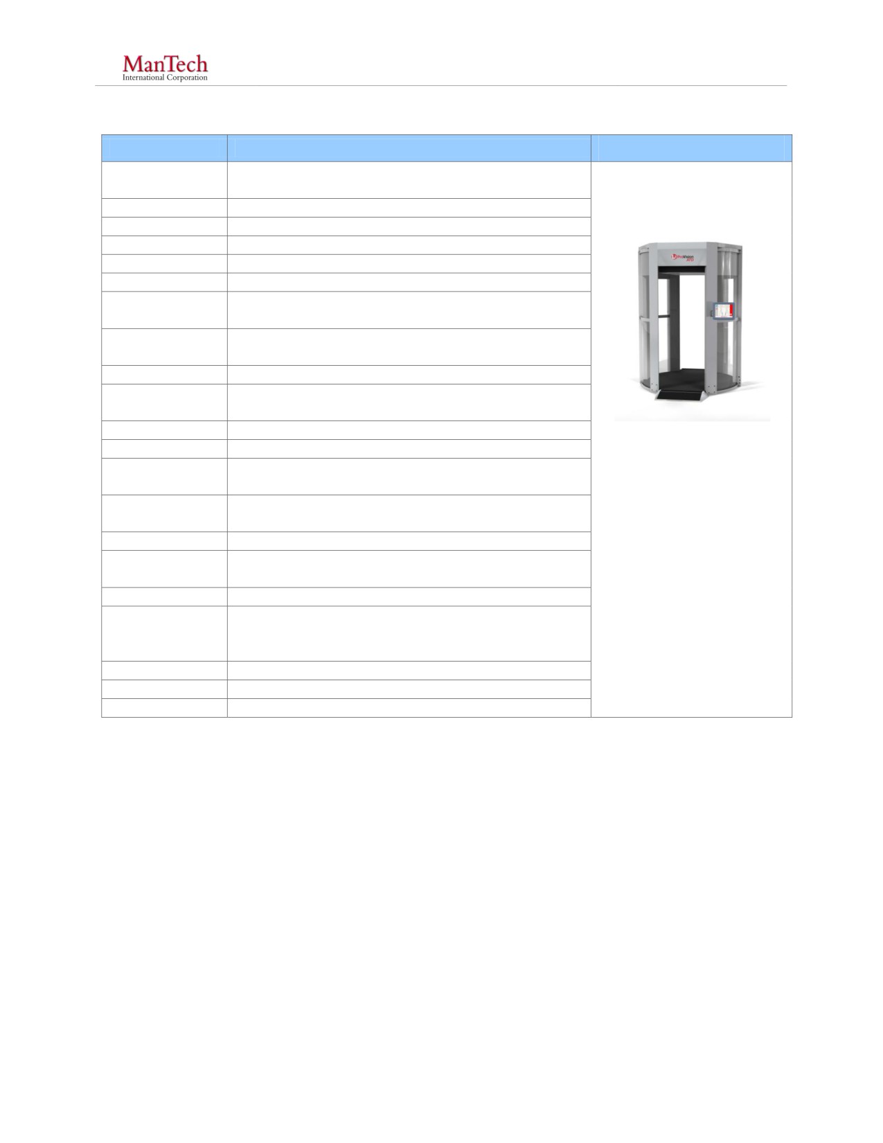
Body Screening Market Survey
April 2014
NIJ SSBT CoE
4.1.2 ProVision ATD
Characteristic
Details[16, 18, 19]
Model and
ProVision ATD
Name
Technology
Active Millimeter Wave
Size Class
Fixed
Dimensions
105 x 77 x 104 inches
Weight
1500 lbs
Detect Metals
Yes
Detect Non-
Yes
Metals
Detect Cavity
No
Concealed
Which Cavities
N/A
Size of Detected
―Detection is consistent with TSA and EU regulations
Objects
for Aviation threats‖
Scan Rate
< 1.5 seconds
Inspection Time
12 - 15 seconds
Figure 6: ProVision ATD
Penetration
2 - 4 layers of typical clothing for indoor environment
Image Reproduced with
Depth
within 6 seconds
Permission
Spatial
< 0.42” (10 mm)
Resolution
Manufacturer:
Info View
Body Location Alarm
L-3 Security & Detection
Image
Systems
Alarm area marked on generic mannequin figure
Visualization
Power
100/240 VAC 50/60 Hz
Regulatory &
UL-61010-1, CFR Title 47 15.107 and 15.109, IEC
3com.com/advancedimagi
Compliance
61000-6-3, IEEE C95.1, Safety Code 6, RSS 102,
ng/provision-at.htm
Safety
ICNIRP
Warranty
1+ Year
MSRP
GSA Schedule: $162,720.40[18]
Other
The ProVision ATD is an active MMW device that is able to detect metallic and non-metallic
contraband, including liquids, gels, rubber, wood, ceramic, powder, and explosives (both sheet
and bulk). The scan can penetrate some body armor (contact vendor for specifics). Potential
contraband is automatically identified by computer algorithms with no image produced. Scan ID,
date, time, and location of alarms produced can also be stored. The system is completely private
with contraband indications displayed on a generic mannequin figure.
UNCLASSIFIED
12
This document is a research report submitted to the U.S. Department of Justice. This report has not
been published by the Department. Opinions or points of view expressed are those of the author(s)
and do not necessarily reflect the official position or policies of the U.S. Department of Justice.

Body Screening Market Survey
April 2014
NIJ SSBT CoE
4.1.3 ProVision 2
Characteristic
Details[16, 18, 20]
Model and
ProVision 2
Name
Technology
Active Millimeter Wave
Size Class
Fixed
Dimensions
93 x 59 x 89 inches
Weight
1500 lbs
Detect Metals
Yes
Detect Non-
Yes
Metals
Detect Cavity
No
Concealed
Which Cavities
N/A
Size of Detected
―Detection is consistent with TSA and EU regulations
Objects
for Aviation threats‖
Scan Rate
< 1.5 seconds
Figure 7: ProVision 2
Inspection Time
12 - 15 seconds
Image Reproduced with
Penetration
2 - 4 layers of typical clothing for indoor environment
Permission
Depth
within 6 seconds
Spatial
< 0.42” (10 mm)
Manufacturer:
Resolution
L-3 Security &
Info View
Body Location Alarm
Detection Systems
Image
Alarm area marked on generic mannequin figure
Visualization
Power
100/240 VAC 50/60 Hz
3com.com/advancedima
Regulatory &
UL-61010-1, CFR Title 47 15.107 and 15.109, IEC
Compliance
61000-6-3, IEEE C95.1, Safety Code 6, RSS 102,
ging/provision-2.htm
Safety
ICNIRP
Warranty
1+ Year
MSRP
GSA Schedule: $177,078.09[18]
Other
The ProVision 2 is a more compact version of the ProVision ATD, and is able to be deployed in
checkpoints with low (2.4 m / 8 ft) ceilings. It is an active MMW device that is able to detect
metallic and non-metallic contraband, including liquids, gels, rubber, wood, ceramic, powder,
and explosives (both sheet and bulk). The scan can penetrate some body armor (contact vendor
for specifics). Potential contraband is automatically identified by computer algorithms with no
image produced. Scan ID, date, time, and location of alarms produced can also be stored. The
system is completely private with contraband indications displayed on a generic mannequin
figure.
UNCLASSIFIED
13
This document is a research report submitted to the U.S. Department of Justice. This report has not
been published by the Department. Opinions or points of view expressed are those of the author(s)
and do not necessarily reflect the official position or policies of the U.S. Department of Justice.
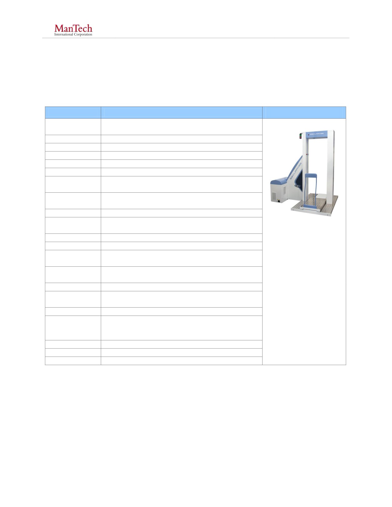
Body Screening Market Survey
April 2014
NIJ SSBT CoE
4.2 Transmission X-Ray Systems
Transmission X-ray systems use X-rays that pass through a subject to reveal contraband hidden
under clothing or even inside the body of the subject.
4.2.1 RadPro SecurPASS
Characteristic
Details[21, 22, 23]
Model and
RadPro SecurPASS
Name
Technology
X-ray Transmission
Size Class
Fixed
Dimensions
101 x 86 x 89 inches
Weight
1433 lbs (650 kg)
Detect Metals
Yes
Detect Non-
Yes
Metals
Detect Cavity
Yes
Concealed
Which Cavities
All
Size of Detected
Spatial Resolution: 0.25 mm
Objects
Figure 8: RadPro
Scan Rate
7 seconds
SecurPASS
Inspection Time
15 - 20 seconds (based on 4 - 5 people per min)
Image Reproduced with
Penetration
Permission
Through Body
Depth
Spatial
Manufacturer:
0.25 mm
Resolution
Virtual Imaging
Info View
Full Body Image
Canon Security
Image
Real Time Dynamic or Scroll Bar
Visualization
Power
110V, 30A
ng-fl.com/
Regulatory &
Compliance
ETL, UL, ANSI
Safety
Warranty
1+ year
MSRP
$215,000
Other
Dose per inspection = 0.25µSv (25µREM) / scan
The SecurPASS is a transmission X-ray system that is able to detect metallic and non-metallic
contraband hidden both on a person and inside the body. Example non-metallic materials that
can be detected include liquids, plastic, powders, paper, and wood. Scans can penetrate ceramic
body armor and steel armor up to 30 mm in thickness. Images can be stored on the device and
are stamped with the time, date, scan number, subject’s name, number and operator’s name. The
device has the ability to track the scan history of an individual or scans can be automatically
saved in a “Daily No ID Folder”. For privacy reasons, images can be masked and a remote
viewing station can also be incorporated.
UNCLASSIFIED
14
This document is a research report submitted to the U.S. Department of Justice. This report has not
been published by the Department. Opinions or points of view expressed are those of the author(s)
and do not necessarily reflect the official position or policies of the U.S. Department of Justice.

Body Screening Market Survey
April 2014
NIJ SSBT CoE
4.3 Backscatter X-Ray
Backscatter X-ray devices detect contraband beneath clothing by imaging the X-rays that scatter
off a subject and their surface clothing/objects.
4.3.1 Rapiscan Secure 1000 DP
Characteristic
Details[24, 25, 26]
Model and
Rapiscan Secure 1000 DP
Name
Technology
X-ray Backscatter
Size Class
Fixed
Dimensions
54 x 36 x 80 inches
Weight
1097 lbs
Detect Metals
Yes
Detect Non-
Yes
Metals
Detect Cavity
No
Concealed
Which Cavities
N/A
Size of Detected
~0.05” (1 mm) metallic; 0.25” (~6.35 mm) non-
Objects
metallic
Scan Rate
6.5 seconds
Inspection Time
24 - 30 seconds
Figure 9: Rapiscan
Penetration
Secure 1000 DP
0.25 - 0.5 inches
Depth
Image Reproduced with
Spatial
~0.05” (1 mm) metallic; 0.25” (~6.35 mm) non-
Permission
Resolution
metallic
Info View
Full Body
Manufacturer:
Image
Rapiscan Systems
Static image reviewed in approximately ~15 seconds
Visualization
Power
120/240 VAC @ 16/8 A
Regulatory &
Safety Act Certified:
ems.com/en/products/ite
Compliance
ISO 9001: 2008 Certified
m/productsrapiscan_sec
Safety
ure_1000_dual_pose/
Warranty
1+ year
MSRP
$124,000
Other
Dose per inspection < 0.05 µSv (5 µREM)
The Rapiscan DP is Backscatter X-ray system that is able image
metallic and non-metallic
contraband including liquids, gels, plastic, wood, ceramic, powder, and paper. The device is
intended to image through clothing, but will not image through body armor. An image is
produced and requires ~15 seconds to analyze. Face masking and remote viewing options are
available for privacy concerns. Standard data records for each scan are available, including scan
time, decision time, and decision result (Clear/Search). All reports are in text and/or CSV format
for easy transport to standard PC programs for printing.
UNCLASSIFIED
15
This document is a research report submitted to the U.S. Department of Justice. This report has not
been published by the Department. Opinions or points of view expressed are those of the author(s)
and do not necessarily reflect the official position or policies of the U.S. Department of Justice.

Body Screening Market Survey
April 2014
NIJ SSBT CoE
4.3.2 Rapiscan Secure 1000 SP
Characteristic
Details[24, 27, 26]
Model and
Rapiscan Secure 1000 SP
Name
Technology
X-ray Backscatter
Size Class
Fixed
Dimensions
142 x 36 x 80 inches
Weight
2194 lbs
Detect Metals
Yes
Detect Non-
Yes
Metals
Detect Cavity
No
Concealed
Which Cavities
NA
Size of Detected
~0.05” (1 mm) metallic; 0.25” (~6.35 mm) non-
Objects
metallic
Figure 10: Rapiscan
Scan Rate
6.5 seconds
Secure 1000 DP
Inspection Time
12 - 15 seconds
Image Reproduced with
Penetration
Permission
0.25 - 0.5 inches
Depth
Manufacturer:
Spatial
~0.05” (1 mm) metallic; 0.25” (~6.35 mm) non-
Resolution
metallic
Rapiscan Systems
Info View
Full Body
Image
Static image reviewed in ~15 seconds
Visualization
ems.com/en/products/ps/
Power
120/230 VAC at 12/6 Amps
productsrapiscan_secure
Regulatory &
_1000_single_pose/
Safety Act Certified:
Compliance
ISO 9001: 2008 Certified
Safety
Warranty
1+ year
MSRP
$220,000
Other
Dose per inspection < 0.05 µSv (5 µREM)
The Rapiscan SP is a Backscatter X-ray system that is able to image metallic and non-metallic
contraband including liquids, gels, plastic, wood, ceramic, powder, and paper. The device is
intended to image through clothing, but will not image through body armor. An image is
produced and requires ~15 seconds to analyze. Face masking and remote viewing options are
available for privacy concerns. Standard data records for each scan are available including scan
time, decision time, and decision result (Clear/Search). All reports are in text and/or CSV format
for easy transport to standard PC programs for printing. The 1000 SP scans the front and back of
a subject at once. This reduces subject interaction and improves throughput as compared to the
1000 DP.
UNCLASSIFIED
16
This document is a research report submitted to the U.S. Department of Justice. This report has not
been published by the Department. Opinions or points of view expressed are those of the author(s)
and do not necessarily reflect the official position or policies of the U.S. Department of Justice.
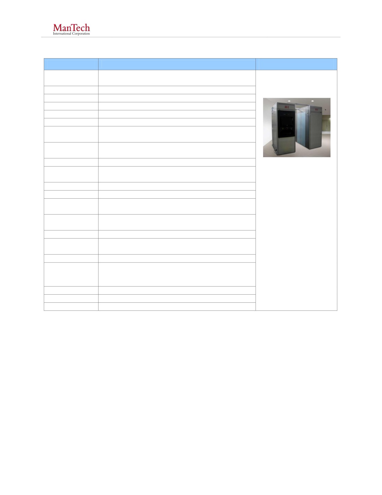
Body Screening Market Survey
April 2014
NIJ SSBT CoE
4.3.3 SmartCheck HT
Characteristic
Details[28, 29]
Model and
SmartCheck HT Inspection Module System
Name
Technology
X-ray Backscatter w/ Edge Transmission
Size Class
Fixed
Dimensions
90 x 64 x 97 inches
Weight
3,000 lbs
Detect Metals
Yes
Detect Non-
Yes
Metals
Detect Cavity
No
Concealed
Which Cavities
N/A
Figure 11: SmartCheck
Size of Detected
~ 1" (metallic), ~ 1 - 2” (nonmetallic)
Objects
HT
Image Reproduced with
Scan Rate
~ 10 seconds
Permission
Inspection Time
~ 15 seconds
Penetration
Proprietary
Manufacturer:
Depth
American Science &
Spatial
~ 0.08” (2 mm)
Resolution
Engineering (AS&E)
Info View
Full Body Image
Image
Real-Time Dynamic Imaging
Visualization
e.com/products-
Power
120 VAC (2 20 amp circuits required)
solutions/personnel-
Regulatory &
screening/checkpoint-
ANSI N43.17-2009, 21 CFR 1020.40, ISO 9001:2000,
Compliance
29 CFR 1910, UL 61010-1A, ISO 1600, 47 CFR 15
lobby/product/smartchec
Safety
k-ht/
Warranty
1+ year
MSRP
$195,000
Other
Dose per scan < 0.1 µSv (10 µREM)
The SmartCheck HT system is a dual Backscatter X-ray system capable of taking three images
simultaneously: two backscatter images (front and back) and one transmission image used to
identify metallic threats on the edges of the subjects image. The system can detect non-metallic
objects, such as liquids, gels, plastic, wood, ceramic, powder, and paper. The device is able to
penetrate non-metallic body armor, and up to 0.25” thickness of steel armor. Photo-like images
are produced; the system has the capacity to store 15,000 images in non-volatile media. The
system can be configured with export to TIF and/or printing. Remote viewing and image
modification (production of an outline of the raw image) are available for privacy concerns.
UNCLASSIFIED
17
This document is a research report submitted to the U.S. Department of Justice. This report has not
been published by the Department. Opinions or points of view expressed are those of the author(s)
and do not necessarily reflect the official position or policies of the U.S. Department of Justice.

Body Screening Market Survey
April 2014
NIJ SSBT CoE
4.3.4 SmartCheck
Characteristic
Details[28, 30]
Model and
SmartCheck Inspection Module System
Name
Technology
X-ray Backscatter
Size Class
Fixed
Dimensions
90 x 64 x 34 inches
Weight
1,500 lbs
Detect Metals
Yes
Detect Non-
Yes
Metals
Detect Cavity
No
Concealed
Which Cavities
N/A
Size of Detected
~ 1" (metallic), ~1 - 2” (nonmetallic)
Objects
Scan Rate
~ 10 seconds
Figure 12: SmartCheck
Inspection Time
30 - 45 seconds (two scans / person)
Image Reproduced with
Penetration
Permission
Proprietary
Depth
Spatial
Manufacturer:
~0.08” (2 mm)
Resolution
AS&E
Info View
Full Body Image
Image
Real-Time Dynamic Imaging
Visualization
e.com/products-
Power
110/220 VAC 50/60 Hz
solutions/personnel-
Regulatory &
ANSI N43.17-2009, 21 CFR 1020.40, ISO 9001:2000,
screening/checkpoint-
Compliance
29 CFR 1910, UL 61010-1A, ISO 1600, 47 CFR 15
lobby/product/smartchec
Safety
k/
Warranty
1+ Year
MSRP
$100,000
Other
Dose per scan < 0.1 µSv (10 µREM)
The SmartCheck system is a Backscatter X-ray system able to detect metallic and non-metallic
contraband including liquids, gels, plastic, wood, ceramic, powder, and paper. The device is able
to detect contraband underneath non-metallic body armor. Photo-like images are produced; the
system has the capacity to store 15,000 images in non-volatile media. Remote viewing and image
modification (production of an outline of the raw image) are available for privacy concerns.
Unlike the SmartCheck HT model, the SmartCheck scans only one side of the subject at a time,
and does not have the option to check the edges of a subject using a transmission type mode.
UNCLASSIFIED
18
This document is a research report submitted to the U.S. Department of Justice. This report has not
been published by the Department. Opinions or points of view expressed are those of the author(s)
and do not necessarily reflect the official position or policies of the U.S. Department of Justice.
Body Screening Market Survey
April 2014
NIJ SSBT CoE
4.4 Thermal Conductivity
Thermal conductivity devices detect contraband underneath typical clothing by imaging slight
changes in temperature that occur on the surface of clothing from concealed objects.
4.4.1 Iscon 1000D Portal
Characteristic
Details[31,32]
Model and
1000D Portal
Name
Technology
Thermo Conductive IR
Size Class
Fixed
Dimensions
97 x 51 x 45 inches
Weight
800 lbs
Detect Metals
Yes
Detect Non-
Yes
Metals
Detect Cavity
No
Concealed
Which Cavities
N/A
Size of Detected
Approximately the size of a single 500 mg pill
Objects
Scan Rate
Varies
Inspection Time
~30 seconds
Penetration
2 - 3 layers of cotton clothing
Depth
Figure 13: Iscon 1000D
Spatial
Image Reproduced with
~ 0.04 - 0.1” (1 - 3 mm)
Resolution
Permission
Info View
Region or Full Body Image
Image
Manufacturer:
Real Time Imaging
Visualization
Iscon Imaging
Power
208 VAC, 10KW
Regulatory &
Compliance
UL / CE Compliant
/iscon1000d.htm
Safety
Warranty
1+ year
MSRP
$110,000
Other
The Iscon 1000D Portal system is a thermal conductivity based system that is able to detect
metallic and non-metallic contraband including liquids, gels, plastic, wood, ceramic, powder, and
paper hidden underneath clothing. The device is not able to detect contraband underneath body
armor. Subtle temperature differences of the subjects clothing are imaged. Because clothing is
imaged, privacy issues are minimized. Streaming video and individual images can be saved
and/or printed.
UNCLASSIFIED
19
This document is a research report submitted to the U.S. Department of Justice. This report has not
been published by the Department. Opinions or points of view expressed are those of the author(s)
and do not necessarily reflect the official position or policies of the U.S. Department of Justice.
Body Screening Market Survey
April 2014
NIJ SSBT CoE
4.4.2 1000M Mini Portal
Characteristic
Details[31, 33]
Model and
1000M Mini Portal
Name
Technology
Thermo Conductive IR
Size Class
Fixed
Dimensions
91 x 59 x 37 inches
Weight
300 lbs
Detect Metals
Yes
Detect Non-
Yes
Metals
Detect Cavity
No
Concealed
Which Cavities
N/A
Size of
Detected
Approximately the size of a single 500mg pill
Objects
Scan Rate
Varies
Inspection
~7 - 11 seconds
Time
Penetration
2 - 3 layers of cotton clothing
Figure 14: Mini Portal
Depth
Image Reproduced with
Spatial
~ 0.04 - 0.1” (1 - 3 mm)
Permission
Resolution
Info View
Region or Full body image
Manufacturer:
Image
Real Time Imaging
Iscon Imaging
Visualization
Power
208 VAC, 30 A
Regulatory &
Compliance
UL / CE Compliant
/miniportal.htm
Safety
Warranty
1+ yr
MSRP
$75,000
Other
The Iscon 1000M Mini Portal system is a thermal conductivity based system that is able to detect
metallic and non-metallic contraband including liquids, gels, plastic, wood, ceramic, powder, and
paper hidden underneath clothing. The device is not able to detect contraband underneath body
armor. Subtle temperature differences of the subjects clothing are imaged. Because clothing is
imaged, privacy issues are minimized. Streaming video and individual images can be saved
and/or printed.
UNCLASSIFIED
20
This document is a research report submitted to the U.S. Department of Justice. This report has not
been published by the Department. Opinions or points of view expressed are those of the author(s)
and do not necessarily reflect the official position or policies of the U.S. Department of Justice.
Body Screening Market Survey
April 2014
NIJ SSBT CoE
4.4.3 GameChangIR
Characteristic
Details[31, 34]
Model and
GameChangeIR
Name
Technology
Thermo Conductive IR
Size Class
Portable
Dimensions
32 x 18 x 11 inches
Weight
80 lbs
Detect Metals
Yes
Detect Non-
Yes
Metals
Detect Cavity
No
Concealed
Which
N/A
Cavities
No Image
Size of
Available
Detected
Approximately the size of a single 500mg pill
Objects
Scan Rate
Varies
Manufacturer:
Inspection
Iscon Imaging
Varies
Time
Penetration
2 - 3 layers of cotton clothing
Depth
/gamechangeir.htm
Spatial
~ 0.04 - 0.1” (1 - 3 mm)
Resolution
Info View
Region or Full body image
Image
Real Time Imaging
Visualization
Power
110/220 VAC 50-60Hz
Regulatory &
Compliance
UL / CE Compliant
Safety
Warranty
1+ yr
MSRP
$25,000
Other
The Iscon GameChangeIR system is a thermal conductivity based system that is able to detect
metallic and non-metallic contraband including liquids, gels, plastic, wood, ceramic, powder, and
paper hidden underneath clothing. The device is not able to detect contraband underneath body
armor. Subtle temperature differences of the subjects clothing are imaged. Because clothing is
imaged, privacy issues are minimized. Streaming video and individual images can be saved
and/or printed. The entire system is portable and folds into its own compact suitcase for re-
location or other transportation
UNCLASSIFIED
21
This document is a research report submitted to the U.S. Department of Justice. This report has not
been published by the Department. Opinions or points of view expressed are those of the author(s)
and do not necessarily reflect the official position or policies of the U.S. Department of Justice.