Military reference books and manuals (2009-2023, Volume 3) - page 27
NATO-UNCLASSIFIED
ATP-17(C)
eastwards into the Barents Sea, and the West Spitsbergen Current, which continues northwards
past Vestspitsbergen to enter the North Polar Basin where the Atlantic water forms an intermediate
warm layer. Part of the West Spitsbergen Current turns westwards off the northern part of
Vestspitsbergen and flows towards the Greenland Shelf. It then turns south and proceeds below
the East Greenland Current as a warmer, more saline, intermediate layer at 175-350 m (95--190
fathoms) depth.
d. The main cold current of the region is the East Greenland Current. This carries ice and Arctic
water, with subzero temperatures and low salinity, from the North Polar Basin along the whole
length of the East Greenland Shelf to round Kap Farvel and enter Davis Strait. There are two
branches of the East Greenland Current: the first, the Jan Mayen Current, flows eastward to the
north of Jan Mayen in the region of the Mohn Ridge. The second, the East Icelandic Current,
flows southeastwards past the northeast coast of Iceland to sometimes reach the north coast of the
Faroe Islands and beyond. A smaller source of Arctic water and ice are the Bjornoya and East
Spitsbergen Currents. These originate in the northeastern part of the Barents Sea and move
southwestwards over the Svalbard Shelf, the former to reach Bjornoya and the latter to round
Sorkapp in Vestspitsbergen and flow northwards between the Vestspitsbergen coast and the West
Spitsbergen Current. The distribution of the sea ice is deterrnined by the East Greenland Current
and its two branches, and to a lesser extent by the East Spitsbergen Current.
e. The speeds of the various currents are not well established. There is evidence to suggest that
there are frequent changes because of the wind. Some estimates put the speeds of the Atlantic
Current and East Greenland Current at 12-24 nautical miles (22-44 km) per day. Locally the East
Greenland Current can reach very high speeds, for example, 3 knots (150 cm/sec) just south of the
Denmark Strait. The basins of the Norwegian and Greenland Seas contain a very nearly uniform
deep water with a salinity of about 34.92 parts per 1000 and a temperature of about-1°C. Seventy
percent of the combined basins is below 550m (300 fathoms) depth and filled with this Norwegian
Sea Deep Water. The mixed water in the upper layers, primarily in the Greenland Sea and to a
smaller extent in the Norwegian Sea, is cooled in winter, but before it can freeze it reaches a
higher density than that of water below it and so sinks to form the Deep Water. In the region of the
Iceland-Jan Mayen and Mohn Ridges, Arctic Intermediate Water appears above the Norwegian
Sea Deep Water and below the Arctic Water of the East Greenland Current system. It has its core
at about 400 m (220 fathoms) depth and has a temperature between 0 and 2° C and a salinity
between 34.8 and 35.0 parts per 1000. It is formed by the cooling of Atlantic Water and mixing
with the Deep Water and, to a lesser degree, Arctic Water. Further south in the Icelandic coastal
area, vertical mixing of Atlantic Water and Arctic Water in winter results in a homogeneous water
in the uppermost 175-350 m (95-190 fathoms). This water has a temperature of 2-3°C and a
salinity of 34.85-34.90 parts per 1000, and is called North Icelandic Winter Water.
f. The Norwegian Sea Deep Water escapes into the North Atlantic Basin through the channel
between Faroe Bank and the Faroe Islands. It flows at the bottom of this channel at a speed in
excess of 2 knots (100 cm/sec) and as it does so the Northeast Atlantic Water, which lies above it,
is entrained into the flow. The resultant mixing produces the Northeast Atlantic Deep Water. This
water mass has minor constituents because, at times, the Arctic Intermediate Water flows through
the same channel and the Norwegian Sea Deep Water, Arctic Intermediate Water and North
Icelantic Winter Water overflow the Faroes-Iceland Ridge, particularly near Iceland, proceed
down its southern flanks, entraining overlying Northeast Atlantic Water as they do so, and
eventually join the outflow from the Faroe Bank Channel as it flows westwards at the foot of the
ridge.
g. The Northeast Atlantic Deep Water eventually turns south when it meets the Reykjanes Ridge;
at about latitude 63°N it breaks through this ridge and flows northwards along its western flanks to
3-13
ORIGINAL
NATO-UNCLASSIFIED
NATO-UNCLASSIFIED
ATP-17(C)
fill most of the Irminger Sea at a depth of 1750-2500 m (950- 1360 fathoms). Above it, in the
Irminger Sea, is Labrador Sea Water with its core at 500-1275 m (275-700 fathoms). This water is
formed as the result of the vertical mixing from the surface to a 1500 m (820 fathoms) depth of
low-salinity water in the Labrador Sea in winter. Below the Northeast Atlantic Deep Water in the
Irminger Sea is the Northwest Atlantic Bottom Water, which originates with the overflow of water
from the Norwegian Sea across the Iceland-Greenland Ridge, in the region of the narrow deep
channel in the Denmark Strait. The overflowing water is at times Norwegian Sea Deep Water and
at times Arctic Intermediate Water. In both cases the overflow proceeds at high speed down the
East Greenland Continental Slope and entrains, first, overlying Irminger Atlantic Water and, later,
Labrador Sea Water and Northeast Atlantic Deep Water, to produce a water mass of high density
which fills the bottom part of the basins of the Irminger and Labrador Seas. Thus, in addition to
there being a counter-clockwise horizontal circulation in the upper part of the water column, with
the Northeast Atlantic Water entering our area and the East Greenland Current leaving it, there is
also a circulation in the vertical plane with the inflow of the Northeast Atlantic Water being
compensated by deeper outflows, over the Scotland--Greenland Ridge, of Norwegian Sea Deep
Water and Arctic Intermediate Water.
Table 3-1 Temperature and Salinity Characteristics of the Water Masses of the European and
American Arctic and Subarctic Seas
Northeast Atlantic Water
9.5°C; 35.35 parts/1000
Irminger Atlantic Water
4.6°C; 34.95-35.10 parts/1000
Arctic Water
< 0°C; < 34.0 parts/1000
Labrador Sea Water
3.4°C potential temperature; 34.89 parts/1000
Northeast Atlantic Deep Water
3.0°C potential temperature; 34.95 parts/1000
Northeast Atlantic Bottom Water
0.8°C 1.5°C; 34.91 parts/1000
Norwegian Sea Deep Water
< 0°C; 34.92 parts/1000
Arctic Intermediate Water
0° - 2°C; 34.8 - 35.0 parts/1000
North Icelandic Winter Water
2° - 3°C; 34.85 - 34.9 parts/1000
Skagerrak Water
3°- 16° C (according to season); < 34 parts/1000
309 EURASIAN COASTAL WATERS
1. Bathymetry
a. The Barents Sea occupies nearly 1 400 000 km2 on the continental shelf of Eurasia. It has free
contact with the Norwegian Sea on the west and with the Arctic Ocean on the north, and it is
deeper than the other peripheral seas, much of it being greater than 185 m (100 fathoms) deep. The
bottom is more like a continental borderland than a shelf, as it has both exceptionally shallow and
deep areas scattered through it. The flat shelf areas are east and southeast of Svalbard and in the
southeastern part of the sea. An east-west ridge at a depth of 185 m (100 fathoms) connects the
shore areas around Z. Frantsa Iosifa with Svalbard, and a north-south ridge at 300 m (165
fathoms) separates the western Bjornoya basin with depths of over 350 m (190 fathoms) from the
eastern basin. The eastern depression extends southwest between Z. Frantsa Iosifa and Novaya
Zemlya with general depths over 275 m (150 fathoms) and occasional depths over 350 m (190
fathoms). In the extreme north there is a third depression between Svalbard and Z. Frantsa Iosifa.
b. The White Sea is a large arm of the Barents Sea that projects more than 270 NM (500 km) into
the European mainland. The approach from the Barents Sea is appropriately called Voronka
(Funnel), and is about 60 NM (110 km) wide. The entrance narrows to the southwest until
between the Kol'skiy P-ov. and the mainland it becomes a strait, called Gorlo (the Throat), 27 NM
ORIGINAL
3-14
NATO-UNCLASSIFIED

NATO-UNCLASSIFIED
ATP-17(C)
(50km) wide, where ice obstructs navigation even when the western, inland and wider part of the
White Sea is reasonably ice-free. The White Sea is mostly less than 100 m (55 fathoms) deep.
Figure 3-4 Water Masses--Norwegian and Adjacent Seas
c. The Kara Sea is exceptionally shallow in the east but relatively deep for its position on the
continental shelf in the west. Off the east coast of Novaya Zemlya there is a 43 NM (80 km) wide
basin that in some places is 550 m (300 fathoms) deep. A ridge in the north of the Kara Sea
separates the basin from the Arctic Ocean. Between Yamal P-ov and Novaya Zemlya there is
another trough of deeper water. There are two more basins in the north of the sea, which have
maximum depths of about 550 m (300 fathoms) and are separated by a ridge. O. Uyedineniya,
Vize and Ushakova form the highest elevations of this ridge. In the southeast of the Kara Sea
depths average only 50 m (27 fathoms) 50-135NM (93-250km) from the shore. The water adjacent
to the Ob and the Yenisey rivers is also exceptionally shallow.
3-15
ORIGINAL
NATO-UNCLASSIFIED
NATO-UNCLASSIFIED
ATP-17(C)
2. Currents
a. The surface characteristics of both climate and sea ice in the Barents Sea result primarlly from
an lnflux of warm water from the Norwegian Sea. This warm current flows north along the coast
of Norway; a southern branch enters the Barents Sea along the north coast of Norway and Kol'skiy
P-ov. as the North Cape Current; the northern branch flows north of Bjornoya and then turns
northwest, passing along the south and west coasts of Svalbard as the West Spitsbergen Current.
Off Varanger Halvoya, the North Cape Current flows at 8 nautical miles (15 km) a day but the
velocity decreases to the east. The current splits at Varanger Fjord, one part flows in a belt 40-50
NM (75-90 km) wide to the entrance of the White Sea, the other curves northeastwards across the
Barents Sea and passes north of Novaya Zemlya into the Kara Sea. This branch is weak in the
north and south of its course, but between 36°E and 44°E it runs at approximately 18 nautical
miles (33 km) a day.
b. The major inflow of cold water into the Barents Sea is between Novaya Zemlya and Z. Frantsa
Iosifa. This current also branches into two parts: one part flows southwest of the archipelago, and
the other west, as the Bear Island Current. In the southeast the general movement of water is
towards the Kara Sea except for the Litke Current, which has the reverse direction. It moves west
through the northern half of Proliv Karskiye Vorota, and then northwest along Novaya Zemlya,
joining the general northerly movement there. In the White Sea is a weak outward current in the
spring and summer, and an equally weak counter-clockwise eddy within the basin.
c. The only important current in the Kara Sea forms a closed counter-clockwise circulation in the
west. The gyre begins in the east with Ob and Yenisey waters which broaden as they leave the
estuaries. One branch flows to Novaya Zemlya where it turns southwest to Proliv Karshiye
Vorota. Within the main circulation are two small weak counter- clockwise eddies. Water also
enters the Kara Sea around the north of Novaya Zemlya from the Barents Sea and eventually
mixes with the Ob-Yenisey waters.
d. Tides in the Kara Sea are semi--diurnal and relatively weak. They come from the Barents Sea
along eastern Novaya Zemlya and from the Arctic Ocean along western Severnaya and progress
southwest. The average amplitude is 0.5 to 1 metre. Winds commonly increase the tidal range by 1
metre or more.
310 EASTERN SIBERIAN COASTAL WATERS
1. Bathymetry. Both the Laptev and the East Siberian Seas are shallow basins with gentle shores.
The edge of the continental shelf is up to 430 NM (800 km) offshore. Only in the northwest Laptev
Sea, off Severnaya Zemlya, are depths greater than 90 m (50 fathoms). The western sector of the East
Siberian Sea south of the Ostrova Novosibirskiye and east to the Kolyma River, is exceptionally
shallow with many shoals. Between the Indigirka and the Kolyma Rivers, and almost continuous
shorebank, defined by the 5.5 m (3-fathom) curve, extends about 24 NM (44 km) out from the shore.
From the Kolyma east to Mys Shmidta, the coastal water is deeper. There are only a few islands, and
these, with the exception of Ostrova Medvezh'i, are close to the shore. The sea deepens slowly to the
northeast; maximum depths are 45-55 m (25-30 fathoms).
2. Currents
a. The general flow of water in both the East Siberian and Laptev Seas is counter-clockwise.
There is a weak, easterly coastal current which is modified by water from the large rivers which
forces it offshore in a northeasterly direction at 1 kt (2 km/h); counter-clockwise eddies develop
when it is caught in coastal indentations. The major current entering the Laptev Sea comes through
ORIGINAL
3-16
NATO-UNCLASSIFIED
NATO-UNCLASSIFIED
ATP-17(C)
Proliv Vil'kitskogo between M. Chelyuskin and Severnaya Zemlya. It is joined by a cold current,
flowing southeastward along Severnaya Zernlya, at 0.2 kt (0.4 km/h) and the combined waters
move along the Taymyr coast into the shallow part of the Laptev Sea. At the Lena Delta the
current splits. One part, flowing along the west side of the Ostrova Novosibirskiye at 0.5-1 kt (1-2
km/h), sets to the north of the archipelago and joins the main Arctic drift. The other part flows
through Proliv Dmitriya Lapteva and other straits into the Eastern Siberian Sea.
b. The waters that pass through the straits separating Ostrova Novosibirskiye and the mainland
spread out on reaching the East Siberian Sea. The main branch near the coast flows at
approximately 0.3 - 1 kt (0.5-2 km/h). A branch of this current is believed to pass north and west
of Ostrov Vrangelya. In summer a current reaches through Bering Strait and flows northwest to
the middle of Proliv Longa; its direction may be reversed in the winter.
c. North of the coastal currents in both the Laptev and the East Siberian Seas, the water flows in
large counter-clockwise eddies. Father north still is a west-northwest current, which runs
northwest at the Ostrova De-Longa and passes north of the Ostrova Novosibirskiye into the
Laptev Sea. It continues northwest across the northern margin of the sea and flows north of
Severnaya Zemlya.
d. Tidal progression is southwards from the Arctic Ocean in both seas. Tides are semidiurnal and
their range is 30 cm, although it may be raised to 3 to 3.5 m with an onshore wind. Tidal currents
flow from 0.5 to 0.8 kt (1 to 1.5 km/h) in the Laptev Sea, but are weaker in the East Siberian Sea.
311 CENTRAL POLAR BASIN
1. Bathymetry and Submarine Topography
a. The Arctic Ocean is a true ocean. Beneath the deepest parts, the crust of the earth is about 10
km thick, a figure that is fairly typical of the other oceans. The Arctic Ocean also shares with other
oceans the characteristic that relief occurs at two predominant levels: the continental shelves with
depths of a few hundred metres, and the deep basins with depths of several thousand metres. A
sharp break in slope between the continental shelf and the continental slope marks the boundary
between the shelves and basins, and defines the edge of the Central Polar Basin. In most oceans,
the shelf break is at about 185 m (100 fathoms) depth, but in the Arctic it is deeper in some
localities (365-475 m: 200-260 fathoms). First recognition that the Arctic Ocean was not a shallow
sea but contained a true deep basin came from the soundings of the Norwegian North Polar
Expedition during the drift of the Fram (1893-1896). The North Pole has been reached twice by
ice-breakers and Arctic exploration has been conducted with aircraft, drifting ice stations, and
nuclear submarines. Oceanographic research proceeded slowly after the successful voyage of the
Fram and it has only been in the last two decades that renewed efforts by the USA and USSR have
resulted in our present level of understanding.
b. Early bathymetric maps of the oceans usually showed smooth and unrealistic contours based
on wire soundings. With the introduction of the continuous echo-sounder, it became clear that the
contours often cut across regions with quite different bottom characteristics. Recently there has
been a trend to analyse the ocean floor in terms of physiographic provinces which cover areas of
similar topographic textures and which contrast with surrounding areas. Almost all the various
provinces found in other oceans, except deep-sea trenches, are known in the Arctic Ocean. The
first--order features are the continental margins and the ocean basins. The continental margin is
made up of the continental shelf, continental slope, continental rise, and marginal plateaux. The
3-17
ORIGINAL
NATO-UNCLASSIFIED
NATO-UNCLASSIFIED
ATP-17(C)
ocean basin consists of ridges, rises, and abyssal plains. A map of the major physiographic
provinces of the Arctic Ocean is shown in Figure 3-5.
2. The Continental Margin
a. Shelves, Slopes and Canyons. The continental margin on the Eurasian side contains some of
the broadest continental shelves in the world. The East Siberian Shelf is 270-485 NM (500-900
km) wide and the Barents and Kara shelves are 380-50 NM (700-1200 km) wide. In contrast the
shelves off Greenland and northwest Canada are only 16-38 NM (30-70 km) wide. North of
Alaska the continental slope has a gradient (1:15 to 1:40) which is comparable to that in other
parts of the world. In contrast, the continental slope between the New Siberian Islands and the
Chukchi Sea is apparently formed of several level surfaces and has been likened to a "giant
staircase". Submarine canyons cut across continental shelves and slopes in the Arctic as in other
oceans. Two prominent ones, Barrow Canyon and Harald Canyon, incise the Chukchi Shelf
between Wrangel Island and Point Barrow. SSN Nautilus, during her 1958 Arctic cruise, made use
of the deeper water of Barrow Canyon to cross the shelf below the ice.
b. Rises and Plateaux. A gently sloping continental rise usually lies at the foot of the continental
slope. North of Alaska, this rise is 27-54 NM (50-100 km) wide. Much greater widths of 160-270
NM (300-500 km) occur in the continental rise off the Canadian Archipelago. A system of deep-
sea channels with a relief of 5 m crosses the Canadian continental rise. A marginal plateau is a
level feature which borders the continental shelf at a greater depth. Several are known in the
Arctic Ocean. The Chukchi Rise is crowned at its outer end by the Chukchi Plateau or Cap which
has a flat summit with a diameter of about 54 NM (100 km) at depths of 300 m (165 fathoms). The
surface is marked by a small-scale relief of 5-30 m. Two submarine canyons indent the southwest
side of the plateau. Southeast of the Chukchi Plateau is an area of rough topography which has
been described as a "continental borderland". Within this area is another plateau, the Northwind
Cap. Other marginal plateaux include the Beaufort Terrace, which on its outermost edge, is
similarly elevated above the saddle which connects to the continental shelf, and the Morris Jesup
and the Yermak rises in the Greenland-Svalbard area.
3. The Ocean Basin
a. Lomonosov Ridge. The Central Polar Basin is crossed by three submarine mountain ranges.
The ridges and rises are nearly parallel to one another and span the basin from the Eurasian to the
Canadian side. A bathymetric profile (Figure 3-6) based on SSN Nautilus soundings, shows two of
these ranges, the Lomonosov Ridge and the Alpha Cordillera. The Lomonosov Ridge stretching
970 NM (1800 km) between the New Siberian Islands and the Greenland-Ellesmere Shelf, was
discovered by Soviet scientists in 1948. It is a single continuous feature, 54-108 NM (100-200 km)
in width. Available echograms show a steep-sided ridge with a rather smooth profile. Minimum
depth reported is 950 m (520 fathoms). Saddles along the crest have depths of 1500-1600 m (820-
875 fathoms). A flat surface near the crest of the ridge has been noted on two different crossings.
An offshoot of the Lomonosov Ridge is known as the Marvin Spur.
ORIGINAL
3-18
NATO-UNCLASSIFIED
NATO-UNCLASSIFIED
ATP-17(C)
Figure 3-5 Physiographic Regions of the Arctic Ocean and Adjacent Seas
b. Other Ridges. The Alpha Cordillera is about the same length as the Lomonosov Ridge but it
is much broader, ranging from 135-430NM (250-800km) in width. The crest of the Cordillera is
1500-1975 m (820-1080 fathoms) deep. Topography is much rougher than that of the Lomonosov
Ridge. The magnetic fields over these two features also differ. The field over the Alpha Cordillera
3-19
ORIGINAL
NATO-UNCLASSIFIED
NATO-UNCLASSIFIED
ATP-17(C)
is rough, with many anomalies exceeding 1000 gammas, while there is little disturbance over the
Lomonosov Ridge. Neither of these ranges is seismically active. The Nansen Cordillera is an
extension of the Mid-Atlantic Oceanic Ridge into the Arctic Ocean. Where the topography has
been sampled, it is rough, as it is on the Mid-Atlantic Ridge. The most distinctive characteristic of
the Nansen Cordillera is the narrow earthquake belt along its crest (Figure 3-7). The belt of
earthquake epicentres crosses Iceland and then changes direction abruptly north of the island,
where a large east-west fracture zone intercepts the mid-oceanic ridge near Jan Mayen Island.
Between northeastern Greenland and northern Siberia, the earthquake belt is narrow and straight
for a distance of over 1080 NM (2000km). Within Siberia, the earthquake zone spreads out and
disappears. In the Atlantic a similar earthquake belt coincides with a central rift valley at the crest
of the mid-oceanic ridge.
c. Abyssal Plains. These are the ultimate repositories for sediments, which have been transported
across the continental shelves and down the continental slopes via the submarine canyons. In the
deep basins the sediments collect to form the most extensive level surfaces on the globe, with
gradients of 1:1000 or less. Four of the abyssal plains in the Arctic Ocean are arranged in step-like
pairs. Each pair is connected by an abyssal gap through which sediments are transported from the
upper to the lower plain. The Canada and Chukchi Abyssal Plains are connected by, the Charlie
Gap. The complete route of sediment flow is from Herald Canyon to the Chukchi Abyssal Plain
and then through the Charlie Gap to the Canada Abyssal Plain; Wrangel and Fletcher Abyssal
Plains are connected through the Arlis Gap. Abyssal gaps are commonly named after the ship of
discovery. In this case, the discovering "ships" were drifting ice stations, Charlie and Arlis,
respectively. Seismic reflection profiles show that a prominent sub-bottom basement ridge exists
in the vicinity of the Arlis Gap. Sediments move from the Siberian Shelf to the Wrangel Abyssal
Plain and then through the Arlis Gap to the Fletcher Abyssal Plain. A system of interplain
channels funnels the flow across the plain and into the gap. The right bank of these channels is
higher than the left bank, apparently due to the influence of the earth's rotation.
Figure 3-6 Topographic Profile Across the Arctic Ocean
d. The most extensive plain in the Arctic Ocean is the Canada Abyssal Plain which covers an
area of 254 000 km2. It is remarkably flat, with depths ranging from 3750 m (2050 fathoms) in the
north to 3850 m (2100 fathoms) in the south. On its northern and western edges, it is bonded by
the scarps of the Alpha Cordillera and Chukchi Rise. The eastern and southern boundaries grade
smoothly into the continental slope. The Pole Abyssal Plain is deeper than the four plains
previously mentioned. In the neighbourhood of the North Pole it is flat and smooth with a depth of
4085 m (2230 fathoms). Away from the Pole the depth of the plain increases to 4575 m (2500
fathoms).
4. Bottom Sediments
a. Light-brown foraminiferal oozes are generally intermixed with sands and gravels on elevated
topography such as ridges and rises. This is known as, a glacial marine sediment. The ooze
represents normal pelagic sedimentation. The sands and gravels are ice-rafted material, which has
been carried out from shore on ice floes and ice islands to be dumped when the ice melted or
broke up. Rocks are often observed strewn over the bottom in deep-sea photographs. The unsorted
ORIGINAL
3-20
NATO-UNCLASSIFIED
NATO-UNCLASSIFIED
ATP-17(C)
ice-rafted rocks range greatly in size. A cobble weighing over 7 kg has been dredged. In bottom
photographs, rocks with dimensions of about one metre have been seen. These rocks show
faceting and striation, which are typical of glacial deposits. On the ridge and rise areas,
sedimendation is extremely slow, only a few millimetres accumulating in 1000 years. Thus many
thousands of years are required to bury an ice--rafted rock. Signs of bottom life are rare in these
regions.
b. Sediments on the Canada Abyssal Plain are greyer in colour and lack the ice-rafted debris
found on the elevated areas. The sediments of the abyssal plains presumably also contain the
pelagic and glacial components but these have been inundated and diluted by turbidity-current
deposits. Turbidity currents originate on continental slopes when oversteepened sediments slump
and flow down submarine canyons a, a slurry of mud and water. They flow and spread out on
reaching the abyssal plain, depositing the mud over the level surface. The coarsest material settles
first so that the beds are usually graded. No rocks are found in photographs taken on the Canada
Abyssal Plain. Signs of animal life, such as intricate patterns of tracks and burrows, are abundant.
c. Seismic reflection profiles give a thickness of about one kilometre for the unconsolidated
sediments near the northern edge of the Canada Abyssal Plain. The thickness must be greater near
the centre of the plain. The same technique has shown at least a 3.5 km thickness of nearly
horizontally stratified sediments underlying the Wrangel Abyssal Plain. The layer of
unconsolidated sediment is much thinner on the ridges and rises. Measurements on the Alpha
Cordillera generally give thickness between 300 and 500 metres.
5. Water Masses. Four water masses are recognized in the Central Polar Basin:
a. The Arctic Surface Water lies between the surface and a depth of 200 m (110 fathoms).
Salinity may be as low as 30 parts per 1000 in this layer at the surface, but it increases rapidly
below 55 m (30 fathoms). Temperature is generally close to the freezing point.
b. On the Alaskan-Canadian side of the ocean, there is a small temperature maximum (-0.7°C) at
about 70 m (38 fathoms), which is known as the Pacific Water. The temperature maximum
decreases with distance from the Chukchi Shelf.
c. The Atlantic Water is marked by positive temperatures between -relatively uniform salinities
of 34.9 to 35.0 parts per 1000 are attained. The depth of the maximum temperature in the Atlantic
Layer increases with distance from its source northwest of Svalbard. It is initially at 300 m (165
fathoms) but increases to 500 m (275 fathoms) north of Alaska. The temperature maximum
decreases with distance from Svalbard from an initial value of 3°C to 0.5°C north of Alaska.
d. The Arctic Deep Water lies between the Atlantic Water and bottom. Temperatures are below
0°C and salinities increase very slowly with depth, from 34.93 to 34.99 parts per 1000. Below
1375-1500 m (750-820 fathoms), the temperatures are 0.5°C warmer on the Canadian side than on
the Eurasian side. These deep waters are presumably formed during cold winters in the Norwegian
Sea. They first enter the basin on the Eurasian side of the Lomonosov Ridge. Some of the water
flows over the saddles in the Lomonosov Ridge to form the warmer bottomwater of the Canadian
side.
6. Tides. Tides in the Arctic Ocean are small. For example, the mean spring tide range at Point
Barrow, Alaska, is only 15 cm. The semi-diurnal tide is derived almost entirely from the Atlantic. It
enters the Arctic Ocean between Svalbard and Greenland, travelling across the Arctic Ocean in about
12 hours as a progressive wave. On the Siberian shelves the tidal currents usually rotate clockwise.
Storm surges may exceed the height of the tides and can cause damage to low-lying Arctic coasts.
3-21
ORIGINAL
NATO-UNCLASSIFIED

NATO-UNCLASSIFIED
ATP-17(C)
Figure 3-7 Earthquakes in the Arctic, January '55--March '64
ORIGINAL
3-22
NATO-UNCLASSIFIED
NATO-UNCLASSIFIED
ATP-17(C)
7. Underwater Sound
a. The propagation of underwater sound in the Arctic Ocean differs in several ways from that in
non-polar oceans. In the Atlantic and Pacific Oceans, the SOFAR channel lies at depths of 1000-
1375 m (550-750 fathoms), but in the Arctic it is at the surface. Low-frequency sound is
propagated to great distances in the Arctic SOFAR channel. Sound rays are alternately refracted
upward in the water and reflected downward from the base of the ice. At great ranges signals
consist predominantly of low frequencies, 8-100 Hz. Roughnesses on the lower surface of the ice
strongly attenuate the high frequencies but have a negligible effect on the low frequencies. Signals
generated by small explosions have been recorded clearly at distances from 43 NM up to about
1620 N M (80-3000 km). Beyond a range of 325 NM (600 km), waves above 100 Hz are very
weak. The Arctic SOFAR signal is dispersed so that an impulsive signal increases in duration as
the range is increased. At a range of 325 NM (600 km) the duration of a signal from a small
explosion is about 5 seconds. At shorter ranges, and over smooth bottoms such as abyssal plains,
bottom-reflected arrivals can be of importance. They are late signals and increase still further the
duration of the signal.
b. In the shallow water of the shelves, propagation characteristics depend strongly on bottom
parameters. In general, long-range transmission is much more strongly attenuated along shallow-
water paths than it is along deep-water paths. Dispersion is even more pronounced in shallow-
water transmission. A shallow sound-scattering layer has been observed beneath the central Arctic
Ocean during the summer months. This scattering layer appears on echograms made at a drifting
station with a 12 Hz sounder. Information on the sound velocity structure of the ocean can be
obtained from measurements of temperature, salinity and depth. For very precise measurements of
these factors at specific depths, Nansen bottles and reversing thermometers are employed.
Information thus obtained can be converted into sound velocity by various methods.
312 ARCTIC OCEAN FRONTS
1. General
a. Ocean fronts are, boundaries separating one water mass from another somewhat like weather
fronts in the atmosphere. Unlike atmospheric fronts however, ocean fronts do not move great
distances, but rather remain in a given area. Because of this, "regional" characteristic ocean fronts
can be classified by the region where they are found and by the characteristic water masses they
separate (See Figure 3-8).
b. Ocean fronts themselves are usually associated with cold or warm currents and can be
influenced by subsurface topographic features such as submarine ridges. In any case, they are
boundaries between water masses of different temperatures, salinities or both.
2. Iceland-Faeroe Front
a. The Iceland-Faeroe Front forms the boundary between the warm, saline Atlantic water and
cold, relatively fresh Arctic water. The front is located near the extension of the submarine ridge
that runs between Scotland and Greenland with depths over the ridge shoaling from 360 to 550 m.
The ridge forms a wall separating the deep waters of the Atlantic Ocean and the Norwegian Sea. It
blocks the flow of most of the nearly homogenous Norwegian Sea Deep Water into the North
Atlantic, thereby affecting the formation and dynamics of the front.
3-23
ORIGINAL
NATO-UNCLASSIFIED
NATO-UNCLASSIFIED
ATP-17(C)
b. Although the surface reflects a rather complex mixing pattern, sea-surface temperature
gradients across the front are present during all seasons. Frontal intensity increases and shows
more definition with increasing depth. At depths of 180 to 275 m, the horizontal temperature
gradient reaches its maximum of -8°C in the winter and -12°C in the summer. Below 275 m,
frontal features weaken and become less defined due to the influence of the nearly homogeneous
Norwegian Sea Deep Water.
c. Although the position of the front is mainly determined by the Iceland-Faeroe Ridge short
period meandering within a 45 NM envelope is not infrequent.
3. Greenland-Norwegian Sea Front
a. The Greenland-Norwegian Sea Front is sometimes referred to as the North Polar Front and is
associated with the Norwegian Current. The Norwegian Current is an extension of the North
Atlantic Current. The current flows northward along the eastern Norwegian Sea at speeds
averaging 0.5 knots and brings warm, saline Atlantic water with it.
b. Like all ocean fronts the Norwegian Sea Front, is the boundary between two water masses of
different temperature-salinity combinations. Atlantic water with temperatures of 6 to 7°C and
salinities slightly greater than 35 parts per thousand are found east of the front. The colder, less
saline waters of the Norwegian-Greenland Seas are found to the west of the front.
c. The Norwegian Sea Front is present year-round, and shows significant short term variability (2
to 3 days). This variability takes the form of cyclonic and anticyclonic meanders and eddies on the
order of 16 to 32 NM. The surface expression of the front is difficult to locate due to wind mixing
of the near-surface waters and the extensive cloud cover limiting the usefulness of satellite
imagery. Because the maximum horizontal temperature gradient is found at a depth of 200 to 300
m, SXBT traces can be extremely useful in determining position.
4. Bear Island Front
a. The Bear Island Front is located midway between Spitsbergen and the Norwegian coast and
results from the interaction of the Bear Island Current and the eastern branch of the Norwegian
Current. The Bear Island Current carries relatively cold, low-salinity Arctic water down into the
northeastern Norwegian Sea. The Norwegian Current, also known as the North Cape Current in
the region, carries modified Atlantic water around the North Cape into the Barents Sea. The
temperature of the modified Atlantic water ranges from 1-7°C at a salinity of about 35 parts per
thousand.
b. The Bear Island Front lies in shallow water in the vicinity of the Bear Island shelf break near
the 90-m curve. The front is closely linked to the bathymetry and shows some light meandering of
about 30 NM from year to year. This phenomenon may be due to periods of northeasterly or
southwesterly winds that favor the transport of Arctic or Atlantic waters respectively, or tidal
effects.
c. Typically, temperatures across the front range from 4-5°C and salinity changes about 1 parts
per thousand. The associated sound speed change is on the order of 21 m/sec. Also, one may
expect a shoaling off the bottom to 185 m in the vicinity of the front.
ORIGINAL
3-24
NATO-UNCLASSIFIED
NATO-UNCLASSIFIED
ATP-17(C)
5. West Spitsbergen Front
a. The West Spitsbergen and Greenland Sea Fronts form the northern and western boundaries of
the large cyclonic gyre. The West Spitsbergen Front forms the boundary between the modified
Atlantic water found adjacent to the southwest coast of Spitsbergen and the colder, less saline
water found in the interior of the Greenland-Norwegian Sea.
b. The temperature gradient associated with the front is evident at the surface where the
temperature changes from an average 7 to 1°C. The warmer temperature is associated with the
modified Atlantic water, which, has a salinity greater than the 34.88 parts per thousand found in
the Greenland-Norwegian Seas.
6. East Greenland Front
a. The East Greenland Front is the result of the East Greenland Current, which is the western
extension of the Spitsbergen Current. The front separates the cold, less saline waters adjacent to
the east coast of Greenland from the warmer, saline water of the Greenland Sea.
b. The water off the coast of Greenland is characterized by seasonal temperatures ranging from-1
to 0°C and salinities from 30 to 34 parts per thousand owing to ice melt. In the summer, strong
vertical salinity gradients may be expected to depths of 15 to 23 m. The intermediate and deep
waters are made up of Atlantic Intermediate Water found to depths of 730 m, temperatures of 0°C,
and salinities of 34.88 to 35 parts per thousand. Below 730 m, Norwegian and Greenland Sea deep
water is found with temperatures less than 0°C and salinities between 34.87 and 34.95 parts per
thousand.
7. Kolbeinsey Front
a. In the region between Iceland, Jan Mayen, and Greenland known as the Iceland Sea, colder,
lower-salinity Polar water exists. The Kolbeinsey Front is the boundary between the Iceland Sea
Water and warmer, saline water adjacent to the west and northern coast of Iceland. The surface
temperature of the Atlantic water ranges from 2°C in the winter to 5°C in the summer.
b. Even in the winter, surface ducts and sound channels should be expected in the Atlantic Water
along the Iceland shelf. North of the front in the Iceland Sea Water, either very weak surface
ducting or half-channel conditions prevail.
8. Denmark Strait Front. The Denmark Strait Front is the boundary between cold Polar water
carried southward by the East Greenland Current and warm Atlantic Water carried north into the
Irminger Sea along the west coast of Greenland. The Front follows the ice edge and continental shelf
break fairly closely, but is known to vary from 30 to 60 NM (See Figure 3-9).
9. Jan Mayen Front. The Jan Mayen Front is located south of the Jan Mayen Island and forms the
boundary between two Arctic intermediate waters of slightly different temperatures and salinities. To
the west of the Front, the water temperature is less than 0°C and the salinity is less than 34.9 parts per
thousand, and to the east of the front temperatures are greater than 2°C and salinity is greater than 34.9
parts per thousand.
10. Norwegian Sea Coast Front. This front is formed when North Atlantic water flowing northward
along the western slope of the Norwegian Trench makes contact with colder, low-salinity waters
flowing from the Norwegian Fiords and the Danish shelf around the Skagerrak. A decrease in the sea-
surface temperature of about-13°C occurs along an eastward crossing of the front. Although the front
3-25
ORIGINAL
NATO-UNCLASSIFIED
NATO-UNCLASSIFIED
ATP-17(C)
characteristics are strongest along the southern coast of Norway, the front is detectable on satellite
imagery all the way to North Cape and into the Barents Sea. The front meanders and generates
numerous eddies on the scale of 54 NM.
11. Murmansk Front
a. The Murmansk Front, also known as the polar Front, forms the boundary between Atlantic
water and Polar water. The Atlantic water flows into the Barents Sea over North Cape with
temperatures ranging from 4 to 12°C and salinities of 34.8 to 35 parts per thousand. As the
Atlantic water moves eastward it begins to cool. Over the central/eastern Barents Sea, the flow
turns northward and splits into two branches south of Franz Josef. The main branch curves west
and further cools and sinks deeper. The smaller branch flows over the north coast of Novaya
Zemlya.
b. The front is rather weak and separates waters of similar temperatures but different salinities.
The Atlantic water has a salinity of about 34.8 parts per thousand in this region while the Arctic
surface water has a salinity of less than 34 parts per thousand. Intense, vertical circulation of water
has been observed in the frontal zone. This mixing provides a good supply of nutrients to the
surface waters, resulting in increased biological activity in the vicinity of the front.
12. Novaya Zemlya and Kara Sea Fronts
a. The extension of the North Cape current that flows over the north coast of Novaya Zemlya
carries highly modified Atlantic water with temperatures around freezing and salinities of 34 to
34.8 parts per thousand into the Kara Sea. The Atlantic water then flows southwest along the coast
of Novaya Zemlya and into the southern Kara Sea.
b. Coastal fresh water input from the Obskaya and Yenisey Rivers amounts to about 940 cubic
km annually. This water is relatively warm and has salinities of from 2 to 20 parts per thousand.
The general flow for this water is northerly into the central Kara Sea. In the southern Kara Sea, the
Novaya Zemlya Front is the boundary between the Atlantic water and the river runoff. A diffuse
front, the Kara Sea Front, exists over the central Kara Sea and forms the boundary between the
Arctic and river runoff waters.
c. Both the Novaya Zemlya and Kara Sea Fronts are seasonal features that begin to develop soon
after the ice melts in the late spring. They reach their peaks in the summer and persist through the
fall.
13. Laptev Sea Front
a. A weak front similar to the Kara Sea Front exists in the Laptev Sea. Fresh water input into the
southern Laptev Sea from the Lena and Olenek Rivers amounts to 554 cubic km per year. This
amount is augmented by the inputs of the Khgatanga and Anabar Rivers into the western Laptev
(no data available on their output). The river runoff water is relatively warm and has salinities that
range from 2 parts per thousand coastally to 28 parts per thousand near the central Laptev Sea.
b. The Laptev Sea Front forms a diffuse boundary between the southern fresh water and the
northern Arctic water, and is more or less a continuation of the Kara Sea Front. Like the Kara Sea
Front, the Laptev Sea Front is seasonally diffuse and therefore not tactically significant.
ORIGINAL
3-26
NATO-UNCLASSIFIED
NATO-UNCLASSIFIED
ATP-17(C)
14. East Siberian Sea Front
a. There are two general types of water masses found in the East Siberian Sea; Arctic and
Siberian Coastal waters. The Arctic water is the same basic water mass found in the northern
Laptev and Kara Seas and has a temperature near freezing and salinities of from 28 to 33 parts per
thousand. The Siberian Coastal water begins to develop after the spring melt and is composed of
input from the Indigirka and Kalyma Rivers. This water is fresher than the Arctic water, with
salinities less than 20 parts per thousand.
b. The East Siberian Sea Front separates the two water masses and extends eastward from the
New Siberian Islands to Ostrov Vranglya (Wrangel Island). The front continues east of Wrangel
Island into the western Chukchi Sea where it serves as a boundary between the Siberian Coastal
water and the Bering Sea water flowing into the Chukchi from the Bering Strait.
c. The East Siberian Sea Front is a weak seasonal front, sharing the same basic characteristics,
which are found in both the Laptev and Kara Sea Fronts.
15. Alaskan Coastal and Beaufort Sea Fronts
a. The Alaskan Front is the boundary between central Chukchi and Alaskan coastal waters
flowing north along the eastern side of the Bering Strait and coastally in the eastern Chukchi Sea
to Point Barrow. Alaskan coastal water originates with fresh water input from Katzebue Sound.
The central Chukchi Sea water is composed of Bering Sea and Arctic waters. The central Chukchi
water is colder and more saline than the Alaskan Coastal water.
b. The Alaskan Coastal Front extends from the Kotzebue Sound coastally to Point Barrow, and is
a relatively weak front (even compared to the East Siberian Sea Front).
c. East of Pont Barrow, the Colville and Mackenzie Rivers provide fresh water input into the
coastal water of the Beaufort Sea. The Beaufort Sea Front forms the boundary between the coastal
water and the Arctic water of the Central Beaufort Sea.
d. The Beaufort Sea Front is a continuation of the Alaskan Coastal Front and is a rather weak
front.
3-27
ORIGINAL
NATO-UNCLASSIFIED

NATO-UNCLASSIFIED
ATP-17(C)
Figure 3-8 General Position of Ocean Fronts
ORIGINAL
3-28
NATO-UNCLASSIFIED

NATO-UNCLASSIFIED
ATP-17(C)
Figure 3-9 Fronts in the Norwegian Sea
3-29(Reverse Blank)
ORIGINAL
NATO-UNCLASSIFIED
INTENTIONALLY BLANK
NATO-UNCLASSIFIED
ATP-17(C)
CHAPTER 4
SEA ICE
401 INTRODUCTION
1. The single feature that makes the Arctic Ocean markedly different from most of the world's oceans
is the presence of a perennial cover of sea ice.
2. Ages and Stages of Development of Sea Ice. There are four broad categories of sea ice age: new,
young, first-year, and old. There are several stages of development that occur within these ages:
a. New Ice. New sea ice is very elastic sea ice that may be up to 10 cm thick. Depending upon
the conditions under which it was formed, new sea ice may have several different stages:
(1) Slush, shuga, frazil and grease ice are all comprised of unconsolidated ice crystals or
platelets.
(2) Nilas is a consolidated form of new ice that remains very elastic. It is divided into dark
nilas (0-5 cm) and light nilas (5-10 cm).
b. Young Ice. Young ice is considerably harder, thicker (10-30 cm), and more brittle than new
ice. There are two subdivisions of young ice:
(1) Grey ice (10-15 cm); and
(2) Grey-white ice (15-30 cm).
c. First-Year Ice. Once ice has grown past 30 cm in thickness, it is considered to be first-year
ice. Although there is no upper limit on the thickness of first-year ice, it generally does not exceed
2 metres. First year ice is subdivided into three categories based on thickness:
(1) First-year thin (30-70 cm);
(2) First-year medium (70-120 cm); and
(3) First-year thick (greater than 120 cm).
d. Old Ice. Old ice is ice that has survived at least one summer's melt. This ice is considerably
less saline and harder than first-year ice. There are no thickness limits on multi-year ice as the
distinction is based on physical properties and not thickness. There are two categories of old ice:
(1) Second-year ice - ice that has survived one summer's melt; and
(2) Multi-year ice - ice that has survived two or more summers' melt.
4-1
ORIGINAL
NATO-UNCLASSIFIED

NATO-UNCLASSIFIED
ATP-17(C)
* Approximately
Figure 4-1 Floe Size
ORIGINAL
4-2
NATO-UNCLASSIFIED
NATO-UNCLASSIFIED
ATP-17(C)
3. Concentration. The amount of ice or the area coverage of sea ice is measured in tenths. The
following descriptions apply to various concentrations:
a. Very open ice - 1 to 3 tenths;
b. Open ice - 4 to 6 tenths;
c. Close ice - 7 to 8 tenths;
d. Very close ice - 9 to less than 10 tenths; and
e. Compact or consolidated ice - 10 tenths.
4. Floe Size. Floe size varies greatly with location and time of year. A descriptive representation of
floe size is found in Figure 4-1.
5. Ice Topography. When driven by the forces of wind, seas and currents, sea ice may take many
forms. As the ice is forced together, it will fracture to raft or ridge on top of itself. When the ice is
forced apart, it will break to form fractures and leads. Similarly, at the ice edge, the forces of nature
may create "ice tongues", "belts and strips", or a "diffuse ice edge". During the summer melt, melt
ponds and thaw holes will appear on the ice.
402 ICE FORMATION
1. When salt is added to fresh water, the temperature at which it freezes is lowered. The higher the
salt content, the lower the freezing point of the salt solution. Seawater, with a salinity of
approximately 32 parts per thousand in the Arctic, freezes at about -1.8°C.
2. Unlike fresh water, the temperature of the maximum density of seawater is lower than the freezing
point (for salinities greater than 24.7 parts per thousand). Consequently, as seawater cool, it becomes
more dense and sinks. Theoretically, in order for ice to form, the entire water column from the surface
to the bottom must be cooled to the freezing point. In reality, only the upper layers of the water
column must be cooled because deep water that is more saline provides the water column stability that
is necessary for ice formation.
3. As the ice forms, there is no room in the crystal structure for the dissolved salts. As a result, these
salts are expelled from the ice. If the ice were formed very slowly it would be practically pure.
However, the freezing process is never a slow one and the salts are trapped within the ice structure as
it freezes. The salinity of sea ice is on the order of 4 to 6 parts per thousand.
403 STRUCTURE AND PROPERTIES OF SEA ICE
1. When seawater is cooled to its freezing point and more heat is removed, ice forms initially as very
thin disks or platelets known as frazil ice. These platelets average 2-3 mm in width and about 0.5 mm
in thickness but vary considerably in shape from hexagonal "snow flakes" to almost square plates. As
further heat is removed, these pure ice crystals grow and multiply. They are less dense than water so
they float to the surface and give the water a slightly oily appearance (grease ice). Further cooling
results in growth of the ice crystals and mechanical entrapment of small brine cells between them.
Ultimately, these cells become separated from the water below the ice by selective downward growth
of the ice crystals.
4-3
ORIGINAL
NATO-UNCLASSIFIED
NATO-UNCLASSIFIED
ATP-17(C)
2. The physical properties of sea ice are almost entirely dependent on its salt content. The detailed
crystal structure, which results dominates these properties to the extent that one can relate any of them
to "brine volume". The brine volume is defined as the fraction of the volume of sea ice occupied by
fluid (liquid brine or air bubbles).
3. The strength of the ice is dependent upon the brine volume. The larger the brine volume, the
weaker the ice is. For this reason, old ice has a much lower salinity than first-year ice, and is much
stronger.
404 ANNUAL ICE CYCLE
1. The process of ice formation has been discussed in some detail in article 402, but this is only the
initial stage of ice growth, which is always dependent upon heat loss from the sea. This heat must flow
upward through the ice layer and through any snow lying on the ice so that the insulating qualities of
these two materials are important factors in determining the rate and amount of ice growth. Air
temperature and the amount of radiant energy falling on the surface are also important factors.
2. In the Arctic, radiation is almost completely dominant in determining the ice surface temperature
and hence the duration of ice growth. This will continue until some time in spring when the increasing
solar radiation changes the heat budget of the ice from a loss to a gain. This usually happens before the
air temperature rises above the melting point of the snow cover. Pure white snow reflects as much as
90 percent of the radiation falling on it, and although the quantity of heat absorbed by the ice is small
at first, the 24 hours of daylight soon result in a gradual increase in the temperature of the ice. When
the air temperature reaches the melting point, the snow surface begins to melt rapidly; it absorbs about
60 percent of the radiant energy and puddles of melt-water become very extensive.
3. In temperate latitudes, the air temperature can contribute to the change from heat loss to heat gain
by the ice, for it can rise above the melting point for appreciable periods, if only in the daytime. The
situation is thus more complicated but the reversal of heat flux is still the controlling factor.
4. Puddling is the first apparent stage of deterioration of the ice cover. The water surface absorbs heat
readily, permitting the puddle to widen and deepen and also to warm the ice. Later, flaws and cracks
develop in the floe through which much of the surface water drains away, leaving dry hummocks of
ice separated by ponds and streams of melt-water. When the ice has this appearance, operations on it
must be carried out with caution for the bearing strength is uncertain and a wind can cause it to break
up rapidly.
5. In temperate latitudes the ice is reduced to a grey, water-saturated matrix (rotten ice), which finally
melts, and the cycle is complete. Farther north, the summer is too brief for complete melting to take
place, and by late August or September puddles begin to freeze and new ice forms between the floes.
After a time the floes themselves start growing again. A floe formed in one year, which survives
through the following summer differs chemically and physically from ice that is less than one year old.
During the summer most of the brine drains out of the ice so that the typical salinity of old ice
(secondary multi-year ice) is about 0.5 to 1 parts per thousand. Melt-water from this ice is quite
potable. The crystal structure of the ice becomes less regular, the crystals themselves are smaller, and
the ice is extraordinarily tough, even in summer.
6. In summer, old floes may be distinguished from first-year ice by their color. The melt-water
puddles on an old floe have a very characteristic pale-blue color, which persists after they freeze. On
first-year ice, these puddles have a green-to-brownish appearance. The old ice itself has a pale-blue
color whereas first-year ice is much more a greenish-white color. The surface of first year ice is
ORIGINAL
4-4
NATO-UNCLASSIFIED
NATO-UNCLASSIFIED
ATP-17(C)
comparatively smooth except for pressure ridges and hummocks. Old ice has a characteristic uneven
surface as a result of the differential melting of puddles and old hummocks.
405 OCCURRENCE OF SEA ICE
1. In the Arctic there are no generalizations that can be made about the occurrence of sea ice in
relation to latitude. This is evident when comparing the winter maximum extent of sea ice in the Sea
of Okhotsk and the Gulf of St. Lawrence, which extend south to 45 degrees North, and winter
maximum extent in the Norwegian Sea, which never penetrates south of 70 degrees North. The
amount of seasonal variation in the sea ice cover is considerable and varies markedly from region to
region. The Permanent Sea Ice Zone is the region that is perennially covered with sea ice. The
seasonal sea ice zone is the region that is ice covered only part of the year and extends from the
summer minimum sea ice extent to the winter maximum sea ice extent.
2. The mean thickness of sea ice varies greatly by region. The average thickness for undisturbed old
sea ice in the central Arctic is about 3.5 m. These thickness averages are misleading because the
dynamic nature of sea ice creates ridges and the corresponding keels in the ice. Ridges of up to 15 m
and keels of over 45 m have been found. This type of ridging is particularly evident where the ice
pressure is impinging upon a coast. Submarine and, ice-breaker observations show that the normal
ratio between ridge height and keel depth is between 1:4 and 1:6, with ridge/keel ratios being observed
over a very wide range.
406 ICE FORECASTING
1. The date of freeze-up of the sea depends on both the oceanographical and meteorological regimes
encountered in the area. Only rarely is the knowledge of water currents, and of the actual temperature-
salinity variations with depth, available for forecasts of this type to be made. The rate of ice growth on
the other hand can be predicted with fair accuracy from meteorological data, as can the maximum
thickness, which will be obtained. It is much more difficult to predict rates of decay, for the process is
slow and long-range predictions of both wind and cloudiness are required for accurate results.
2. One of the most important forecasting problems is ice motion. The general pattern of sea ice
motion in the Arctic is indicated in Figure 4-2. Recent studies have revealed that 70 percent of the ice
motion is due to wind forcing. This pattern is of course affected by tides and currents as well as, land
masses, and bathymetric features such as shoals. A general rule of thumb is that the ice will drift about
45 degrees to the right of the wind direction at about 2 percent of the wind speed.
4-5
ORIGINAL
NATO-UNCLASSIFIED

NATO-UNCLASSIFIED
ATP-17(C)
3. Ice routing information for the Arctic can be obtained from the following national agencies:
Nation
Agency
Services Offered
CAN
Environment Canada,
Information on ice conditions such as ice hazard bulletins and
Canadian Ice Center, Ottawa
special warnings for ships are freely available through weather
and marine radio broadcasts. Commercial products including
detailed ice analysis charts and radar and satellite imagery are also
available. A detailed listing of products and services can be
accessed at http://www.cis.ec.gc.ca.
CAN
Canadian Coast Guard Ice
Ice routing information for the Canadian Arctic can be obtained
Operations
via any Coast Guard Radio Station. Further information on
contacting Ice Operations may be obtained from the Ice
Navigation in Canadian waters (TP 5064E).
DNK
Danish Ice Information
Ice charts of the areas East, West and South of Greenland are
Service (DIIS),
promulgated on a regular basis. Ice charts and ice reports can be
Narssarssuaq, Greenland
obtained from all Greenland Coastal Radio Stations and on the
internet at http://www.iserit.greenet.gl/isc/ice.
DEU
Federal Maritime and
Ice routing information can be obtained from this civil agency.
Hydrographic Agency
E-mail: ice.at.bsh.d400.de. Internet site at
http://www.bsh.de/oceanography/ice/ice/htm.
CINCGERFLEET does not maintain a special agency but can
provide ice routing information upon request. This information is
primarily available for the North Sea and Baltic but is also
available for other areas. Messages should be sent to
CINCGERFLEET for GEOPHYS, SIC JOG.
GBR
CINCFLEETWOC
The position of 10 percent of the ice edge is shown on routine Sea
Surface Temperature fax charts. This data is not available west of
045W.
USA
National Ice Center (NIC),
The NIC provides operational sea ice analyses and forecasts for
Washington
the Arctic, Antarctic, Great Lakes and Chesapeake Bay. Their
products and services can be accessed at
http://www.natice.noaa.gov.
USA
US Coast Guard
The USCG IIP monitors ice conditions in the vicinity of the Grand
International Ice Patrol (IIP),
Banks of Newfoundland, and pending severity, broadcasts the
Groton CT
Southeastern, Southern and Southwestern limits of all known ice
in two daily message bulletins. The IIP can also provide a daily
fax chart containing ice information. For a comprehensive listing
of products and services and instructions on accessing them use
the IIP homepage at
http://www.uscg.mil/lantarea/iip/home.html.
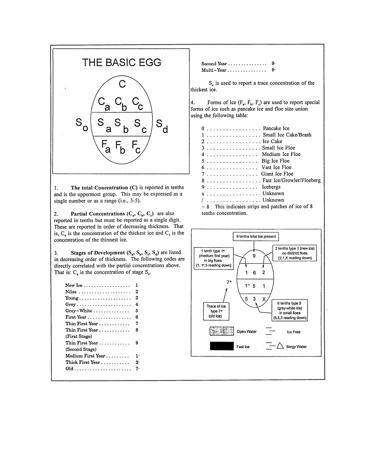
Sea ice
information is encoded according to the World Meteorological Organization
(WMO)
symbology known as the egg code, due to the oval shape of the symbols. The egg code shown in
Figure 4-3 provides information on types and concentrations of ice in each area of the chart. Figures 4-
4 and 4-5 are examples of charts distributed by the Center using egg code symbology.
407 OTHER ICE ENCOUNTERED AT SEA
1. River Ice. There is appreciable difference in the strength of freshwater ice and sea ice, and
consequently, in or near the estuaries of major rivers an additional hazard to shipping may be
ORIGINAL
4-6
NATO-UNCLASSIFIED

NATO-UNCLASSIFIED
ATP-17(C)
encountered in the spring when river ice is carried into the sea. This is particularly true of the rivers of
the Soviet Arctic.
2. Ice Islands. These are masses of ice that have broken away from an ice shelf and have an
undulating surface. They may have thicknesses of up to 60 m with areas of up to 400 km2. In the
final stages of melting they usually break up into a group of tabular icebergs.
3. Icebergs. Icebergs are large masses of freshwater ice and compacted snow that have broken away
or "calved" from a glacier. The Greenland Ice Cap is the single largest source of icebergs, with the
largest concentration of icebergs found in Baffin Bay and the Davis Strait. In the East Greenland Sea
icebergs are found imbedded in and sometimes outside the drift-ice, particularly south of Scores by
Sound. Icebergs have been found in excess of 90 m in height and 500 m in length. Their draft varies
from two to more than 10 times their height due to their irregular shapes. Iceberg location information
can be obtained from the International Ice Patrol. Icebergs do not always travel in the direction of the
wind. They have a small sail area relative to total size and travel in the direction of the current, which
may be against the wind. Figure 4-6 shows the general drift pattern of Atlantic icebergs. Figure 4-7
shows typical areas where icebergs can be anticipated in the Pacific region.
Figure 4-2 General Pattern of Ice Movement in the Arctic Ocean
4-7
ORIGINAL
NATO-UNCLASSIFIED
NATO-UNCLASSIFIED
ATP-17(C)
Figure 4-3 Egg Code Symbology
ORIGINAL
4-8
NATO-UNCLASSIFIED

Figure 4-4 (Sheet 1 of 6) Summer Ice Limit Charts

Figure 4-4 (Sheet 2 of 6) Summer Ice Limit Charts

Figure 4-4 (Sheet 3 of 6) Summer Ice Limit Charts

Figure 4-4 (Sheet 4 of 6) Summer Ice Limit Charts

Figure 4-4 (Sheet 5 of 6) Summer Ice Limit Charts

Figure 4-4 (Sheet 6 of 6) Summer Ice Limit Charts
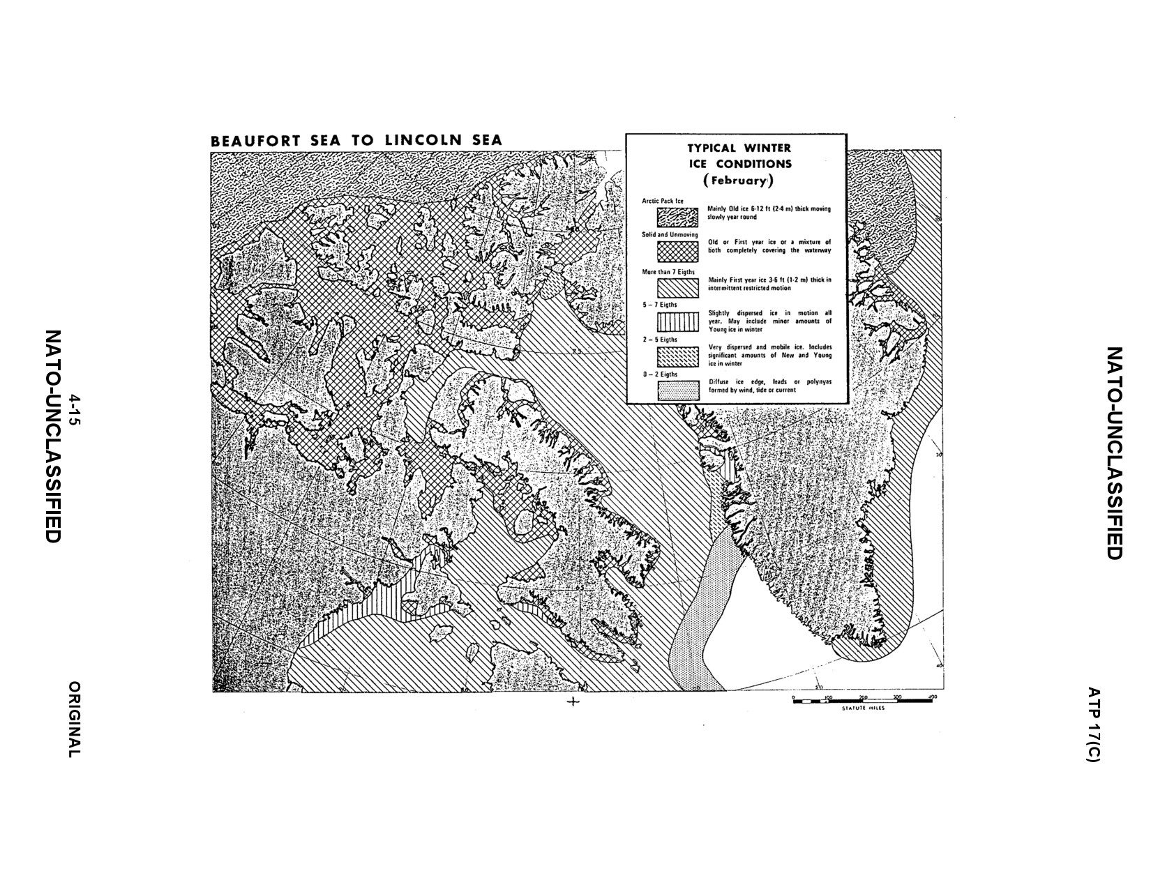
Figure 4-5 (Sheet 1 of 3) Winter Ice Limit Charts

Figure 4-5 (Sheet 2 of 3) Winter Ice Limit Charts

Figure 4-5 (Sheet 3 of 3) Winter Ice Limit Charts

NATO-UNCLASSIFIED
ATP-17(C)
Figure 4-6 General Drift Pattern of Atlantic Icebergs
ORIGINAL
4-18
NATO-UNCLASSIFIED

NATO-UNCLASSIFIED
ATP-17(C)
Figure 4-7 Pacific Ocean Icebergs
4-19 (Reverse Blank)
ORIGINAL
NATO-UNCLASSIFIED
INTENTIONALLY BLANK
NATO-UNCLASSIFIED
ATP-17(C)
CHAPTER 5
GENERAL PREPARATIONS FOR ARCTIC OPERATIONS
501 GENERAL
1. Weather conditions in the North Atlantic, particularly during winter, can be more severe than those
experienced above the Arctic Circle during the short navigation season. Indeed, the Arctic summer can
be quite pleasant, with warm sunshine, temperatures well above freezing, dear skies, little wind, and,
because of the dampening effect of ice, calm seas. There is, in fact, a threat of sunburn and a definite
need for sunglasses.
2. Climatic and other environmental conditions affecting ships and their equipment during Arctic
operations includes:
a. Low surface air temperatures at certain seasons.
b. Sudden changes in air temperatures.
c. High winds.
d. Low seawater injection temperatures.
e. Low humidity.
f. Ice conditions ranging from slush and brash to solid pack.
g. Snow, sleet and freezing rain.
h. Fog and overcast, occurring at the ice/water interface.
i. Heavy seas with attendant spray in areas clear of pack-ice.
j. The possibility of heavy and rapid ice accretion, with consequent loss of stability.
k. Abnormal magnetic conditions and low directivity of magnetic compasses.
l. The possibility of gyro compass errors.
502 TOPSIDE PREPARATIONS
1. Prevention of Slippery Decks
a. Ensure that deck tread ladders, and deck nonskid areas meet safety standards (renew
if
necessary). Non-skid areas can be expanded to enhance traction.
b. Thin ice can be removed most effectively from decks and other flat surfaces by the use of dry
chemicals such as sodium chloride (rock salt), calcium chloride and urea. These materials are
simply spread over the frozen surfaces in a thin layer as required. Rock salt is the most economical
material and is effective above -9øC. Calcium chloride gives off heat when mixed with water so it
5-1
ORIGINAL
NATO-UNCLASSIFIED
NATO-UNCLASSIFIED
ATP-17(C)
acts faster than rock salt. A mixture of one part calcium chloride and three parts rock salt will be
effective to temperatures of-18°C.
c. Urea
(granular or pellets) is effective for melting thin layers of ice above-9°C and for
preventing ice accumulation in freezing rain.
d. Sand can be used alone or in combination with any de-icing chemicals to improve traction on
ice-covered decks.
2. Develop procedures for entry, egress, and safety of topside personnel:
a. Topside personnel must use two-man buddy system.
b. Topside personnel will need to be tethered with tended safety lines during heavy weather.
c. Temporary lifelines and guide-ropes can be run along flight-decks attached to tiedowns (during
non-flying hours) to permit watch personnel crossing on LPDs and LPHs.
3. Lubricate all topside fittings with appropriate cold-weather greases.
4. When selecting covers for equipment, the most important characteristics to look for are strength,
durability and water resistance. Non-porous, fire-retardant covers are recommended for
(at a
minimum):
a. Ship's boats. (Complete boat must be covered.)
b. Davit winches.
c. Capstan/windlass and associated controls. (Because of exposure to severe weather forward,
extra covers will be required.)
d. Unheated combat system equipment.
e. Sound-powered phone boxes.
f. All outside (exposed) command, control, communications stations.
5. Precautions taken to protect hydrostatic release mechanisms on life rafts should include the fitting
of polyethylene sleeves over the devices and sealing them.
6. Develop and promulgate ice accretion removal procedures and instructions to avoid damage to
equipment or undue hazard to personnel during removal operations.
7. Obtain and install, when necessary, temporary shelters or windscreens for exposed personnel and
topside watch-keepers.
8. Rig, when necessary, additional life and safety lines for protection of personnel. Heavy-weather
lifelines should be rigged well in advance to facilitate early identification and correction of
deficiencies. Set up cargo lines on lifelines at UNREP stations to prevent line handlers from falling
overboard.
ORIGINAL
5-2
NATO-UNCLASSIFIED
NATO-UNCLASSIFIED
ATP-17(C)
9. Ice removal equipment and de-icing materials should include those items listed in Tables 5-1 and
5-2.
10. Firemain valves topside will have to be cracked sufficiently to prevent freezing. Run an old hose
section over the side to prevent ice buildup. Securing the risers from below deck is effective, as is
filling piping and stations with antifreeze.
11. Topside Damage Control Equipment
a. Fire hoses and nozzles will perform satisfactorily at freezing temperatures and below, provided
water is kept flowing and a good pressure is maintained. If the pressure is reduced or the hose is
secured, the nozzle and plug may become frozen. If a long lead of hose is to be secured at
temperatures below -12 øC, stop the flow only for the time necessary to disconnect each length of
hose. After securing, hoses and nozzles should be taken below decks and completely dried prior to
returning to topside stowages.
b. Duplex proportioners should be drained after use, dismantled, dried, oiled, and the chamber
change-over valves reassembled. Oxygen-breathing apparatus (OBA) with spare canisters should
be returned to below-decks stowage as soon as no longer needed.
c. Portable water pumps should be stowed below decks.
d. External connections on the firemain will need to be isolated and drained or kept on a tickle
flow. Dead ends or low flow spots such as magazine or cargo storeroom sprinkles on the firemain
should be watched closely to avoid freezing.
503 SHIP'S BOATS PREPARATION
1. The use of boat engine heaters (engine block, oil system or cooling system) will ensure easier
starting. Equipment from auto parts stores such as dipstick heaters are effective. Other means to keep
boat engines warm include heat lamps, flood lights, drop lights and insulation blankets.
2. Utilize antifreeze in engine cooling water system to prevent freezing. Cold-weather lubricants and
oils should be used for engines and transmissions. Circulating water heater and heat strips around
engine block and oil pan is effective. Ethylene glycol (60/40) in the bilges and saltwater pumps will
prevent ice buildup.
3. Install and utilize boat jump-start connections. A constant trickle charge is recommended.
4. Obtain spare boat batteries.
5. Lubricate and protect davits and winches. Boat falls can be prevented from birdcaging by keeping
them clean, and running the winch machinery to heat lubricants prior to use.
6. Fabricate boat covers for each boat. The cover must protect the entire boat down to the water-line
and should be made out of heavy canvas, not herculite.
7. Ensure that procedures are developed to drain salt-water cooling systems and top off fuelling
systems daily.
8. Ensure that adequate repair parts are available.
5-3
ORIGINAL
NATO-UNCLASSIFIED
NATO-UNCLASSIFIED
ATP-17(C)
9. During very cold conditions, provisions must be made for periodically starting and warming boat
engines if no use, is expected to be made of them. Time frame varies from once daily to once per
watch, depending upon the weather.
10. Lubricate entire boat throttle cable to prevent freezing and binding.
11. Not only may boats become damaged by ice, they can also be cut off from their parent ship by
poor visibility or by drifting ice floes brought down by a change of wind or tide. Thus all boats should
be equipped with emergency rations and survival kits including first-aid supplies, sleeping bags,
firearms, and a suitable selection of hand-held pyrotechnics. In addition, all boats ought to be radio-
equipped. Boats' crews should always have their cold-weather clothing with them while away from
their ship. For larger boats, an inflatable life-raft ought to be carried, and all boats should be fitted with
radar reflectors.
12. Additional suggestions include:
a. Hoisting slings may need reinforcement for rough-weather handling of boats.
b. Wooden boats should be copper-sheathed along the water-line, especially forward.
c. Foam flotation material (e.g., styro-foam), which must remain impervious to both water and
fuel, should be applied to boats to provide an additional measure of buoyance in the event they are
holed by ice. Boats in excess of 9 m should have some form of watertight subdivision for the same
reason.
d. In Arctic service, outboard motors are reliable and efficient. While damaged propellers can be
easily repaired or replaced, consideration should also be given to the fitting of some form of
propeller guard.
e. Fuel tanks should be kept topped up in order to minimize condensation.
f. Fill drinking water containers in boats to only
75 percent capacity to avoid bursting the
containers.
504 MOORING LINES AND ANCHOR GEAR PREPARATIONS
1. Mooring lines should be kept dry and stowed under cover when not in use. Manilla lines can freeze
and dry rot if exposed to cold for long periods. Polypropylene and polyethylene lines absorb little
water but are stiff and brittle in the cold. Nylon and darcon lines, particularly braided type, aborb more
water but remain easy to work with.
2. Particular attention should be paid to the small sizes of wire rope where the component wires are
of small diameter, since frost and ice can cause them to break.
3. When proceeding in waters calling for constant use of soundings, steps should be taken to ensure
that anchors and cables are ice-free and ready for use at short notice.
505 ENGINEERING PREPARATION
1. Window Heaters
ORIGINAL
5-4
NATO-UNCLASSIFIED
NATO-UNCLASSIFIED
ATP-17(C)
a. All heaters must be checked, and their operability ensured, before leaving port.
b. Overheating may cause lamination to separate on windows, so ensure that temperature
controlling mechanism is functioning.
c. Determine means to clear ice from area in front of bridge windows. Using the window wash
system, with a water/antifreeze (50/50) fluid mix, is an effective de-icing method. Ensure wash
system is operated after addition of water/anti-freeze solution to purge fresh water from system
piping.
2. Turbine and Ventilation System Intakes
a. Provisions must be made to ensure that intakes are cleared of snow and ice. Accumulation can
be controlled by the use of LP air to blow snow from demister pads.
b. Ensure that turbine de-icing systems and inlet heaters are operable and effective.
3. Sea-Chest Inlet and Outlet Blockage
a. Use steam blow-out connections or LP air to de-ice engineering intakes.
b. Monitor freezing of overboard discharges, such as CHT, and develop an ice removal plan for
these systems.
4. Main Engineering Plant Spaces
a. Check all air reducers by operating them at their proper pressure and ensure that they can be
adjusted so that a drop in air pressure in cold weather can be overcome.
b. Add sufficient antifreeze to diesel freshwater system to preclude freezing.
c. Obtain extra batteries for all requirements. Battery locker temperature should be maintained
above 15°C or store batteries elsewhere.
d. Monitor water/steam usage during ice removal operations. Inefficient ice removal may lead to
excessive water usage.
e. Install insulation behind and above main switchboards where condensation may form.
f. Ensure that a full allowance of damage control and repair material such as shores, plates,
clamps, wedges and plugs are on board.
g. Monitor temperature of idle machinery.
h. Prepare evaporators for cold-weather operations. Prior to sailing, hydro the freshwater side of
the evaporators. Locate and fix all leaks. Use new gaskets when reassembling the units. Check air
ejector nozzles for proper operation. The best way to maintain capacity is to start with a "tight
plant".
i. Very high vacuums occur during cold-weather operations. Throttling the main condenser
overboard valve to control condensate depression does not work well. Use of the masker belts
5-5
ORIGINAL
NATO-UNCLASSIFIED
NATO-UNCLASSIFIED
ATP-17(C)
causes air to be entrapped, and air may bind the main condenser. Venting of the condenser
regularly has proven effective in maintaining vacuum and efficient engine operations.
5. Interior Space Heating and Ventilation
a. Ventilation heater controls should be adjusted to maintain space temperatures of 19- 20°C in
lieu of 21-27°C. This will minimize the drying effect in living compartments, since the relative
humidity of the compartment air will be greater at the lower space temperature differential for
personnel going to and from topside or exposed locations.
b. Machinery space ventilation fans should be operated to give a slight positive pressure within
the area. This will avoid creating drafts through the ship proper and will conserve the heat in the
interior of the ship. All living space ventilation supply fans should be operated on low speed to
reduce the amount of outside air taken into the ship.
c. To avoid freezing of ventilation heaters, it is essential that condensate lines are kept open and
that traps are in proper operating condition.
d. To ensure that blowers are operated at low speed, that thermostats are not tampered with, and
that thermostatic traps or preheaters are operative, it is suggested that a heating patrol be
established as part of each watch. This procedure is particularly recommended for large ships
engaged in low-temperature operations. A roving watch, checking berthing spaces, fan rooms and
heating boundaries, has proven effective.
506 TOWING CONSIDERATIONS
1. Long Stay. Ships operating in Arctic waters should be equipped and ready to tow or be taken in
tow at short notice. Towing at long stay can be difficult because ice, if there is any present, can get
between the ships involved. Some ice-breakers are equipped with a notched stern, suitably padded, in
which the stem of the ship to be towed can be secured. Ships with high freeboards, however, are
unsuited for this method.
2. Short Stay. Towing at short stay can be undertaken though the ship towed should not use its
engines because of the risk of overrunning and striking the towing vessel.
507 ICE PREPARATIONS/CONSIDERATIONS
1. Removal Techniques
a. Topside icing can result in a dangerous loss of stability, reduction in reserve buoyance, and
critical impairment of a ship's ability to withstand damage. Other adverse effects are the increased
load on decks, masts, and other structures, and the danger that men will slip on icy decks or be
struck by falling ice from aloft.
b. There are various methods by which ice can be removed:
(1) Manual. Ice is broken away and chipped off using mallets, clubs and scrapers. Caution
must be exercised to avoid damage to metal surfaces, electric cables (including degaussing
cables) and equipment. Ships should lay in a stock of wooden mallets, shovels, wire brooms
and scrapers suitable for the removal of ice and snow. Table 5-1 provides a list of ice removal
equipment.
ORIGINAL
5-6
NATO-UNCLASSIFIED
NATO-UNCLASSIFIED
ATP-17(C)
(2) Steam Jet. A steam lance can be used to undercut layer ice as, for example, in freeing an
anchor which has become frozen in its hawse pipe. It can also be used for spot heating.
(3) Anti-Icing Coatings. These coatings can be used to protect comparatively small areas or
items. Anti-icing compounds retard the formation of ice and contribute somewhat to the ease
of its removal.
(4) Heated Salt Water Under Pressure. This is sea water heated to at least 50°C, or higher
if possible. It is used in high- pressure steams to slot, undercut, and break up large
accumulations of ice. No attempt is made to melt ice directly, but rather to break it up or
weaken it to facilitate removal. When using water to clear ice, scuppers and overboard drains
must be clear.
(5) De-icing. Use of Ethylene Glycol, Methanol or other de-icing chemicals can be used to
remove ice build-up on exterior surfaces.
2. Superstructure Icing Considerations
a. When severe topside icing occurs and ice continues to accumulate, despite all attempts to
remove it, it may become necessary to alter course, heave to, or make for an area of more
moderate weather. Icing can occur when heading into strong winds and heavy seas and in
conditions of low air and seawater temperatures. Smaller ships having low free boards and reserve
stability are particularly vulnerable.
b. The rate of ice accretion from ocean spray is related to surface wind speed roughness of the
sea, air temperature
(below
1.67°C), and duration of exposure. Figure
5-1, the Overland
Monograms, offer the most current prediction method for icing conditions.
c. The smaller the vessel, the more serious the problem of ship icing. Any prolonged exposure to
gale-force winds and below-freezing air temperatures could ultimately result in the vessel
capsizing. Fishing trawlers approximately 52 m long have capsized and sunk as a result of rapid
ice accumulations on the hull and superstructure; freezing spray accumulating at a rate of two tons
an hour over a period of 24 hours has been reported. Meteorological observations taken in the
vicinity of Iceland indicate that storms of gale force accompanied by freezing air temperatures and
lasting as long as three days may occur as often as three times a year. Sparseness of synoptic
meteorological information in this area makes forecasting of such prolonged periods of gale-force
winds and below-freezing temperatures quite difficult.
d. The use of aircraft engines can be effective in removing snow from around closely parked
aircraft. Rock salt should not be used because of its corrosive effect on metals.
508 CARGO HANDLING CONSIDERATIONS
1. Cargo should be stowed in such a manner that it cannot shift as a result of repeated impacts between
the ship and the ice. It should be stowed well away from the sides of the ship thus allowing easy
access to the side plating in case of damage and to permit passage of water to the bilges. Ships
operating in ice, should be so loaded that they will be trimmed by the stern. If in ballast, consideration
should be given to flooding so as to immerse the rudder and propellers to minimize the risk of damage
to them by ice.
5-7
ORIGINAL
NATO-UNCLASSIFIED
NATO-UNCLASSIFIED
ATP-17(C)
2. Helicopters should be fitted with hoisting gear and quick - release hooks. There may be occasions
when ice floes block beach unloading sites, or ice-pack prevents a ship getting close enough to employ
boats and landing-craft effectively.
ORIGINAL
5-8
NATO-UNCLASSIFIED

NATO-UNCLASSIFIED
ATP-17(C)
Table 5-1 Ice Removal Equipment
5-9
ORIGINAL
NATO-UNCLASSIFIED

NATO-UNCLASSIFIED
ATP-17(C)
Table 5-2 De-icing Materials
ORIGINAL
5-10
NATO-UNCLASSIFIED

NATO-UNCLASSIFIED
ATP-17(C)
Figure 5-1 The Most Recent Nomograms (Overland et al. 1986)
5-11 (Reverse Blank)
ORIGINAL
NATO-UNCLASSIFIED
INTENTIONALLY BLANK
NATO-UNCLASSIFIED
ATP-17(C)
CHAPTER 6
HULL, ENGINEERING AND ELECTRICAL
601 COLD-WEATHER PREPARATIONS
1. Check all heating and cooling systems.
2. Check coolers for leaks. Weather leakage can occur because of contracting of the tubes in the
cooler tube sheet/plate due to colder salt-water inlet temperatures.
3. Identify unheated or inadequately heated spaces. Air, cooling-water, salt-water, and other lines
running through spaces should be insulated for protection. Heaters should be installed. Portable items
subject to freezing should be moved to heated spaces. Other ad hoc measures to improve temperature
control include fans and other ventilation techniques to draw warm air from other areas. Additional
heating will be needed to maintain crew comfort.
4. Check areas where condensation and frost may form on interior metal surfaces adjacent to exterior
bulkheads.
a. Hatches, doors and lagging buttons are likely to be most frequently affected. If interior ambient
temperature is cool, heavy frost will form. If interior spaces warm up, condensation will drip onto
deck and equipment.
b. More insulation may be needed on exterior bulkheads, overheads, and especially on doors and
hatches.
c. Check all watertight doors' gaskets and knife/sealing edges.
5. Where it is determined that spaces require portable heaters, check wiring set-ups. Ensure that vital
electronic equipment (navigation gear, etc.) is not wired to the same circuit breaker as a high-
amperage portable heater.
602 EXPOSED PIPING AND SCUPPERS
1. Overflow pipes from fresh water gravity tanks should be led inside the ship to a warmed scupper
and not be allowed to drain onto an open deck. Deck-edge waterways should be kept clear of
obstructions so that a clear passage will exist when snow is being washed down.
2. Lagging by itself will not keep liquid in a pipe from freezing if the ambient temperature falls
below the freezing point. Liquid must be warmed and kept in continuous motion; failing this, heating
of all the piping lying outside the insulated structure will be necessary.
603 HULL DAMAGE AND REPAIR IN THE ICE
1. Ice damage can take the following forms:
a. Bending or loss of propeller blades.
b. Steering gear damage, including the rudder head and/or the rudder.
6-1
ORIGINAL
NATO-UNCLASSIFIED
NATO-UNCLASSIFIED
ATP-17(C)
c. Propeller shaft fracture.
d. Damage to the stem, puncturing and tearing of plating.
e. Buckling of plating and the tearing out of rivets due to ice pressure.
2. Should the steering gear break down in a single-screw ship, it may be possible to steer with the aid
of two rudder pendants secured to the rudder and led to a stern capstan or cargo winch.
3. Although every reasonable precaution may have been taken against damage to a ship, it is possible
that damage or breakdowns will occur which will be of such a nature as to necessitate major repairs. In
such circumstances, ships should be detached and directed to the nearest shipyard or be taken under
tow.
604 STOWAGE SPACE REQUIREMENTS
1. Additional stowage space will be required to accommodate Arctic equipment and material. Space
will also be required for the stowage of anti-ice compounds and liquids.
2. Crew members will need extra stowage space for their gear. Space should also be set aside for
Arctic clothing in living spaces or in compartments immediately adjacent thereto. Similarly, suitable
facilities should be provided for the drying of heavy Arctic clothing.
3. Allot additional stowage space for food storage since a 10 percent increase in food consumption
will be experienced.
605 FRESH WATER SUPPLY
1. Suction pipes in freshwater storage tanks should be insulated to prevent ice from blocking the
lower ends.
2. Freshwater gravity and any similar tanks fitted in exposed positions should be heated and amply
lagged. Arrangements should also be made to warm the pressure switch gear if fitted. Leads of
freshwater supply and drain pipes must also be lagged and heated if they lie outside an insulated
structure.
606 SALT WATER SUPPLY
1. Leak-offs should be fitted at the ends of the firemain to assure a continuous circulation of water.
These leak-offs must be at least 13mm in diameter, be well lagged, and discharge either directly
overboard or into a scupper with a warmed non-return flap valve.
2. Firemain risers can have water secured at the main deck, or for flight deck supplies use antifreeze
in the riser itself.
3. Salt-water hydrants fitted in exposed positions should be isolated inside the main structure, and
arranged so that the exposed length of the hydrant supply pipe can be drained and left empty in cold
weather.
4. Careful attention must be paid to the lagging of salt-water supply pipes which, although not
directly exposed to weather, can be subject to low temperatures, e.g., those fitted in the hangar of
ORIGINAL
6-2
NATO-UNCLASSIFIED
NATO-UNCLASSIFIED
ATP-17(C)
aircraft-carriers near lift openings.
5. Careful attention must also be paid to spraying arrangements in ready-use magazines, to similar
compartments in exposed positions, and to magazine-flooding lockers if these are located on weather
decks.
6. Fire pumps should be capable of taking their suction from the discharge side of a main engine or
generator condenser or cooler, so that warm water can be delivered to the fire main.
607 GENERAL INSTRUCTIONS FOR MACHINERY
1. Machinery space temperatures should be maintained at or above 4.4oC.
2. In systems containing a mixture of glycerine and water, a check on the homogeneity of the mixture
should be made by taking samples from both the top and the bottom of the mixing tank, and testing
with a glycerometer. A homogeneous 50/50 mixture will remain completely fluid down to -27oC. A
60/40 mixture will remain fluid down to -40oC.
3. When engines which have salt-water cooling systems are not required for immediate use, the
circulating water system should be kept empty. Engines with a freshwater cooling system should have
the system charged with an approved antifreeze solution. The raw water side of the heat exchanger
system should be drained. Glycerine and water should not be used as an antifreeze solution. Because
of the fine clearances in the water pumps of both types of cooling systems, drops of water remaining
after draining may cause seizure of the pump, so pumps should be warmed before turning the engines.
608 EXPOSED EQUIPMENT
1. Particular attention should be given to equipment on deck, to guard against congealing of lubricant
or formation of ice. Covers should be used, where possible, to maintain all equipment at operable
temperatures.
2. Pressure gauges in exposed positions should be disconnected when non-essential.
3. When removing ice from any mechanism by use of steam jet, care should be taken to avoid ingress
of steam which will condense and freeze on interior working parts.
609 GENERAL INSTRUCTIONS
1. Fire Hoses. Hoses should be drained, dried, and stowed below deck.
2. Fire Extinguishers. Foam-type and soda-acid extinguishers should be stowed in a warm place.
Arrangements should be made to ensure that the supply from the firemain for continuous foam is
warm and that foam compound is stowed in a position protected from the cold.
3. Arrestor Gear and Safety Barrier System. Heating should be provided to air-reducing valves
fitted in the arrestor gear and barrier system to prevent freezing.
4. Telemotor Systems and Hydraulically Operated Mechanisms. These should be charged with a
50/50 mixture of glycerine and water or a national approved liquid as directed, and be tested
periodically.
6-3
ORIGINAL
NATO-UNCLASSIFIED
NATO-UNCLASSIFIED
ATP-17(C)
5. Pressure Gauges. Except where they are essential, pressure gauges in exposed positions should be
removed.
6. Motor Boats. To prevent damage to the engines and to ensure that they can be started when
required, the following precautions should be taken:
a. An external source of heat should be provided to maintain the engines and pipe systems at a
reasonable temperature. It may also be necessary, under conditions of extreme cold, to warm the
lubricating oil and diesel fuel tanks.
b. When engines are not in use, or at "short notice", the seawater circulating system should be
kept empty. Engines with freshwater cooling systems should have them charged with an approved
anti-freeze solution. To facilitate draining the system, drain cocks should be fitted where necessary
to drain water from any pockets in the system. On account of the fine clearances in the water
pump, small drops of water remaining after draining may be sufficient to cause seizure of the
pump if the temperature has not been above -2.2oC. To avoid damage to the pump, special
measures should be taken to warm the pump before turning the engine.
c. Full use should be made of devices fitted to assist cold starting of diesel engines, such as
heater plugs, ether, etc.
610 INSULATION
Thermal insulation should be applied to the shell and bulkheads behind and above switchboards if
such areas suffer from condensation. All cold-weather piping and equipment such as fire, sanitary and
freshwater systems, soil pipes and freshwater tanks should be insulated where damage to equipment or
discomfort to personnel may result from dripping condensate. All ventilation supply and exhaust
ducting and heaters, including flanges and joints, must be insulated to prevent sweating and heat loss.
611 GAS CYLINDERS
Pressure in compressed gas cylinders subjected to cold temperatures will drop considerably and may
be insufficient for practical use. Therefore, bottled gases should be stowed inside if safety regulations
permit. If they are used directly from an outside stowage in cold weather, as much as 2m3(75ft3) of
volume can be lost.
612 BATTERIES
1. Cold temperatures drastically reduce the output of all types of batteries (both dry cells and storage
batteries). For example, at -18oC, the ampere-hour capacity of a typical dry cell battery is reduced to
about 25 percent of the 20oC rated capacity. At this temperature, capacities of lead-acid and nickel-
cadmium storage batteries are down to about 35 percent and 50 percent respectively.
2. The lowest temperature for reliable cranking is about -18oC. The output of all batteries reaches
essentially zero at about -34oC to -40oC. The rate at which storage batteries can accept a recharge is
also reduced in cold temperatures. To obtain a good recharge in a reasonable amount of time, the
temperature of the battery should be about 15oC or higher.
3. The sulphuric-acid electrolyte in a discharged acid battery can freeze at -15oC. If the battery is
fully charged, the electrolyte freezing point is depressed to
-60oC or below. Freezing may damage the
plates, crack the battery case, split the cover-to-case seal or the terminal-to-cover seal, thus leading to
electrolyte spillage. Freezing of electrolyte may also form crystals which can pierce separators,
ORIGINAL
6-4
NATO-UNCLASSIFIED
NATO-UNCLASSIFIED
ATP-17(C)
eventually leading to internal short-circuits and premature failure of the battery.
4. The potassium hydroxide electrolyte in a nickel-cadmium battery does not vary significantly with
the state of charge and the freezing point is essentially constant at -60oC. Freezing of this type of
battery is not a problem.
5. Storage batteries should be kept fully charged and stowed in a heated space or equipped with
heaters.
6. Flashlight and other dry cell batteries should be kept warm when not in use.
7. For more detailed information on handling of batteries in a cold environment, see Annex D.
613 SHIP COLD WEATHER SOAKING
1. Ship cold weather soaking is defined as long-term exposure of the ship to sub-zero temperatures
and near freezing seas. The ship gradually reaches thermal equilibrium with its environment after
about a two to three week exposure. The ship is considered cold-soaked when the heat loss rate drops
to the same point as the heat production rate. The net heat transfer rate is zero and therefore the
amount of heat the ship contains is constant.
2. When a ship transits from a moderate climate to a cold climate, its exterior and topside equipment
will cool down to ambient temperatures. Low seawater temperatures may cause high vacuums in
condensers, condensation on air and seawater pipes and low temperatures in cooling systems. Spaces
near the skin of the ship and interior spaces containing seawater piping and/or unheated ventilation
will cool rapidly, particularly unheated spaces. After an initial rapid drop, air temperatures in these
spaces will stabilize into a slow downward drift until the soak is complete.
3. Spaces below the waterline have a low temperature limit of approximately -2.2oC. However, heat
is lost more easily at the water/hull interface than at the air/hull interface. One effect of this is that
ship's skin temperatures above the waterline may be higher than those below the waterline even
though air temperatures are well below freezing. Topside exterior spaces, subject to solar heating,
wind and weather, can experience temperatures far below seawater temperatures and wider, more
frequent temperature variations.
4. As temperatures in the outer spaces fall, temperature drops will progress toward the ship's interior.
In general, once soaking is complete, the spaces farthest from the exterior of the ship will be the
warmest; however, the locations and sizes of heat sources and/or whether the fresh air supply is heated
will have the greatest effect on which parts of the ship will have cold problems.
5. Exterior Effects of Soaking. The exterior of the ship (and all equipment located there) is
essentially at the temperature of the environment.
6. Non-Arctic internal combustion engines, such as those found on small boats, will be difficult to
turn over without Arctic-grade oil. Engine fuels will thicken and suffer from wax formation. Water in
the fuel will freeze causing fuel flow blockage. Diesels, in particular, become increasingly harder to
start as the weather gets colder. High fuel viscosity may prevent proper oil flow through the engine,
once it has been started. Tighter clearances due to cold-induced contraction can exacerbate these
effects. The film of lubricant protecting engine internals and separating surfaces such as
journal/bearing and piston ring/cylinder breaks down more quickly at cold temperatures, allowing
adhesion (engine seize) and corrosion to occur.
6-5
ORIGINAL
NATO-UNCLASSIFIED
NATO-UNCLASSIFIED
ATP-17(C)
7. Unprotected freshwater engine cooling systems may experience fractured heat exchangers and/or
popped freeze plugs.
8. Interior Effects of Soaking
a. Unheated Spaces. Because many unheated spaces are infrequently occupied, damage to items
in those spaces could go unnoticed. Cold spaces containing low or no-flow water lines are of
particular concern. An example of such a space is an unused head, often found on ships designed
to carry embarked troops. Prolonged cold weather could also cause damage to the contents of
storage spaces.
b. Heated Spaces. Ships have reported that typical heated space temperatures reached the 10oC
range during long-term Arctic exposure. Living and working in temperatures of around 10oC
increases fatigue, as has been reported from previous ships operating in a cold-soaked condition.
The constant discomfort has generally diminished the ability of the crew to perform at its best.
c. Engineering Spaces. Under normal conditions, engineering spaces do not require additional
heat to maintain acceptable living temperatures. However, during cold weather operations, a
number of ships have experienced the need to shut down part of engineering space ventilation in
order to keep ambient temperatures above freezing.
d. Ships have reported the need to make impromptu modifications to the ventilation system line-
up in order to keep engineering space air above freezing temperatures. Only the waste heat
emanating from the various engineering systems keeps conditions in these spaces from being as
severe as the exterior of the ship.
e. Condensation/Standing Water. During prolonged cold weather operations, condensation can
occur on the coldest interior surfaces of the ship, leading to preservation problems, water damage
and slippery surfaces. Freshwater in contact with the hull will freeze, including bilge water and
condensation. Ice build-up can occur on the inside, especially in humid spaces. Frozen bilges will
impair the ship's dewatering capability if the bilge suctions are covered. Hatches and scuttles will
become frozen shut down from the inside.
f. Condensation will occur on any piece of equipment taken from a cold storage area into a warm
space. Of particular concern is electronic equipment. Condensation hazard to electronic gear arises
when a cooling medium operates at temperatures below the design point. Significant delays can be
expected during start-up while electronic gear warms up and stabilizes. Condensation occurring
inside fuel tanks can freeze. Prevent condensation by insulating or lagging cold surfaces and using
a desiccant to lower humidity in small spaces.
9. In-Port Effects of Soaking. A ship tied to the pier in a cold weather environment gets colder
faster than when it is at sea. A large amount of heat-producing equipment is normally shut down.
Likewise there can be a lack of sufficient shore power and use of the ship's own resources means the
use of fuel and watchstanders.
614 YELLOW GEAR
1. Operational yellow gear in cold weather is very important. Failure of vehicles, which move aircraft
equipment, supplies or ammunition could interrupt ship's operation.
ORIGINAL
6-6
NATO-UNCLASSIFIED
NATO-UNCLASSIFIED
ATP-17(C)
2. Normal greasing, filter cleaning, electronics and hydraulic checks are extremely important. Just as
essential are the use of fuel, oil and lubricants designed to allow the vehicles to operate effectively and
efficiently in cold weather.
3. The use of ether starting systems already installed on the vehicles or manual applications of ether
to the air intake regions will provide the necessary cold weather starting assistance. Ether canisters
should be stocked in sufficient quantities to ensure quick starts throughout the deployment. Excessive
use of ether damages the internal seals and gaskets of the engine. An engine may need to be
overhauled in warmer temperatures after being started with ether.
4. Air tanks on all yellow gear vehicles should be drained daily. The air drain should be left open to
allow all condensate to drain and to prevent freezing the air lines. Use of air dryers and their
maintenance will be covered in vehicle maintenance manuals.
5. Cold weather affects pneumatic equipment as much as diesel or gas equipment or vehicles, so
preventive maintenance and daily checks for moisture in the system needs to be accomplished.
Pneumatic systems should be fitted with dryer units which use methanol.
6. Cold weather can cause severe stress on metal. Inspections of the yellow gear stress points, the
fork lift carriage and points where hydraulic cylinders attach to the frame need to be completed to
ensure no corrosion or stress fractures are evident prior to the deployment.
615 UNDERWAY REPLENISHMENT
1. Training. Before a cold weather cruise, personnel should receive training on special aspects of
cold weather Underway Replenishment (UNREP) operations, including:
a. Cold weather hazards of hypothermia and frostbite.
b. How to function in special cold weather clothing.
c. Proper relieving procedures.
d. General cold weather UNREP operations.
2. Preparation for UNREP. As a preventive measure, covers for deck equipment should be
provided, where possible, to reduce the penetration of water and subsequent formation of ice. Because
of cold weather effects on UNREP equipment, more time and effort must be devoted to getting the
equipment ready to begin UNREP operations:
a. Ice and snow must be removed from covered and uncovered equipment, including decks and
hatches.
b. De-icing chemicals will be needed to remove ice from equipment and decks.
c. Equipment must be started and operated at low speed to check for proper operation and to
allow warm-up prior to full speed operation.
d. The non-skid surface should be extended to cover as much deck area as possible.
6-7
ORIGINAL
NATO-UNCLASSIFIED
NATO-UNCLASSIFIED
ATP-17(C)
e. The technical manuals for all UNREP equipment exposed to the weather should be reviewed to
determine what cold weather lubricants and hydraulic fluids will be needed.
f. Some specific preparations for UNREP include:
(1) Grease wire ropes and sheaves.
(2) Put cold weather hydraulic fluid in winches and cold weather lubricating oil in the winch
gear boxes.
(3) Drain the water and purge the moist air from compressed air systems to prevent freezing
of on-deck pneumatic equipment. Check air dryers to ensure that the dew point temperature of
the compressed air is maintained within the proper range.
(4) Make room below decks to store all small equipment and fibre ropes used during UNREP
operations. Break equipment out when needed and replace it below when the operation is
completed.
(5) Procure winch covers to protect UNREP equipment from spray and to facilitate de-icing
without damage to equipment by ice removal tools. These covers should be part of the ship's
"Cold Weather Kit".
(6) Check the gaskets in refuelling probes and bellmouths to preclude leaks during refuelling
operations. Stock extras because gaskets may become brittle and crack in cold weather.
(7) Stock a large supply of chemlites because they will lose intensity after an hour or two in
cold weather, and because of the reduced number of daylight hours.
(8) Fiberglass reinforced plastic traction mats may be obtained which give effective traction
even when partially iced over.
(9) Stock alkaline flashlight batteries rather than the ordinary cells. Alkalines are degraded
less by cold temperatures.
(10) Conduct an electrical check to ensure traffic lighting and other necessary control
measures are operational.
g. Provide for portable, topside heaters or enclosures for personnel involved in extended topside
evolutions. Hangar space heaters have proven effective.
h. Anticipate that routine evolutions could take twice as long in cold weather.
i. Periodically inspect berthing spaces for warmth and ventilation. Ensure that adequate bedding
materials are available.
j. Provide for additional heaters for particularly exposed areas, such as the Signal Bridge and
Pilot House.
k. Hot beverages and soup should be available on the mess deck 24 hours a day and distributed to
look-outs, RAS and flight-deck crews.
l. Stripping of waxed decks and the addition of non-skid strips is recommended.
ORIGINAL
6-8
NATO-UNCLASSIFIED
NATO-UNCLASSIFIED
ATP-17(C)
CHAPTER 7
COMBAT SYSTEMS
701 COLD-WEATHER PREPARATIONS
1. Gun Mounts, Missile Launchers and Torpedo Tubes.
a. Check topside mounts for watertightness.
b. Check drive motors.
c. Ensure that heating coils/base ring heaters are operable.
d. Obtain additional seals, plugs, and O-rings to provide redundancy, since cold temperatures
increase the failure rate.
e. Ensure that window heaters are operable.
f. Lubricate with required oils and greases. (Old grease will have to be purged.)
g. Verify that the installed heating system can maintain hydraulic oils above 15oC, or provide
supplementary heaters.
h. Check the magazine sprinkler systems for proper operation and insulation of piping in
unheated spaces. Pipework to upperdeck magazine lockers should be insulated and is best drained
down to an isolation valve within the ship.
i. Ensure that instructions for the operation of these systems in extreme cold weather are
prepared. Include the following:
(1) Protection of exposed hydraulic lines, high-pressure air piping, and gas ejection piping.
(2) Use of heat strips in gun barrels. (Insert/retract from breech.)
(3) Protection of electrical cables.
(4) Use of cold-weather hydraulic fluids and lubricants.
(5) Monitoring of cooling and other fluid systems for leakage.
(6) Regulation of inlet pressure on CIWS cooling water to maintain required temperature.
(7) Increase of frequency of routine checks and movement of systems through full arcs. If
seizure is considered possible, operate systems initially in "hand control".
j. Openings into mountings of breech mechanisms should be fitted with removable canvas
covers, including separate covers for gun sights and breeches of guns.
k. Due to cold moisture in air systems, valves may freeze open, causing constant HP air leaks.
Secure valves until weather improves. This will lock snubbers and retaining latch, requiring delay
7-1
ORIGINAL
NATO-UNCLASSIFIED
NATO-UNCLASSIFIED
ATP-17(C)
in firing.
l. Torpedo tube heating system must be checked. It may be necessary to regularly fire air slugs.
m. Launcher barrels should be checked for build-up of condensation after heaters have been left
switched on for 2 days or more.
2. All Sonars, Torpedo Countermeasure Hoists and Towed Arrays
a. Verify operability of installed heaters.
b. Obtain spare seals, particularly for topside, exposed hoists.
c. Lubricate with cold-weather greases.
d. Ensure that hydraulic oil is maintainable above 15oC, or obtain supplementary heater.
e. Equipment cabinets and other components may develop condensation because of cold
temperatures. Transmitters may have to be dried out before applying full power.
f. Towed Array System/VDS
(1) The hoist motor can be operated to keep the hydraulic fluid warm, and the drum rotated
in case retrieval or adjustments to scope are required.
(2) Minimize body/tail surface time. The array could be damaged by floating ice if allowed
to remain near the surface for any length of time.
(3) The electrical components of the hoist are exposed to icing and mechanical damage when
towed body array is deployed. Additional covers should be added.
(4) Ensure that transom door latches are checked. A means of "dogging" the doors securely,
allowing an absolute minimum of play, is highly advised. Chain falls are one possibility.
(5) Strive to maintain interior spaces water-free during towing operations.
(6) Have available means of de-icing (chemical/thermal) for the towed body and cable if
required. (De-icing fluid is preferred.)
3. Prairie Masker
a. The use of the forward masker belt, particularly below cavitation speeds, may result in the air
binding of intakes for cooling fire pumps.
b. When a masker must be used, it may be necessary to find alternate cooling or fire pump
intakes, or reconfigure supply arrangements for cooling/firemain.
4. Canister Launchers
a. Cover exposed launchers to reduce icing and remove prior to use.
ORIGINAL
7-2
NATO-UNCLASSIFIED
NATO-UNCLASSIFIED
ATP-17(C)
b. Protect canister seals and covers to prevent cracking.
c. Maintain canister temperature in accordance with technical manuals, and monitor periodically.
d. Check vent dampers' operability during cold-weather operations. Cycling weekly is effective.
702 FIRE CONTROL RADARS
1. For simple tachymetric directors, suitable switch sockets should be fitted near each director for use
with electric blankets and portable electric heaters.
2. Prior to entering cold weather, the antenna drive motors should be tested and lubricated with cold
weather grease. Grounding straps should be insulated with RTV compound.
3. Shafts and bearing surfaces will operate more effectively if they are buffed and polished. Such
surfaces should be lubricated sparingly.
4. More detailed guidance is provided at paragraph 803.1.g.
703 RECOIL MECHANISMS
Recoil mechanisms containing a glycerine and water mixture will function satisfactorily in cold
weather. However, sluggish action and a short recoil may become apparent at those temperatures
below freezing when crystals form in the mixture, although the solution will not freeze until
temperatures below the pour point are reached. Heat must be applied as soon as unsatisfactory recoil
action is experienced. The orifices in recoil mechanisms are designed for a specific mixture of
glycerine and water and no substitution is permitted.
704 AIRCRAFT GUNS
1. For reliable operation at low temperatures, guns must be clean and properly lubricated. When
firing in sub-freezing temperatures, gun heaters are required and should always be turned on just
before take-off.
2. Before firing, guns should be disassembled, cleaned, inspected for defects or part breakages, and
lubricated. While disassembled, it should also be determined that all traces of hard-drying
preservatives have been removed from all working parts of the gun.
3. It is important that all springs be within their prescribed tolerances of free length.
4. All traces of solvent used in cleaning must be removed before reassembly. Incomplete removal of
the bore cleaning solvent may result in malfunctioning at low temperatures. Immediately after
cleaning, if guns are to be ready for firing, they should be lubricated with the prescribed lubricant. If
guns are to be stored after cleaning, a suitable preservative must be applied.
5. Apply oil sparingly. Never dilute lubricating oils with kerosene. Cold-temperature tests have
shown that gun operation at low temperatures is not improved by diluting the lubricating oil in such a
manner. Further, at temperatures warmer than -29oC, this mixture is not a satisfactory lubricant.
6. Guns rust rapidly from condensation when taken from the cold into a warm building. After
reaching room temperature, they should be stripped, their parts wiped thoroughly dry and clean and
7-3
ORIGINAL
NATO-UNCLASSIFIED
NATO-UNCLASSIFIED
ATP-17(C)
immediately oiled. This procedure must be repeated every time guns are brought into a warm space
from the cold outside.
705 GUN SIGHTS AND AIRCRAFT FIRE CONTROL EQUIPMENT
All gun sights and aircraft fire control systems should be capable of operating at temperatures as low
as -48oC, provided the correct lubricants are used.
706 BOMB SIGHTS AND BOMB DIRECTORS
Most bomb sights will perform satisfactorily at low temperatures. Some have proved to be satisfactory
to
-54oC while others, of a less elaborate type, will operate at temperatures to -40oC.
707 AMMUNITION
1. Ammunition must be kept in protected storage at temperatures not below the minimum safe values
prescribed for the explosives concerned. Ensure wet ammunition is wiped down prior to stowage to
prevent icing. Propellants should be maintained at a temperature above -17.7oC. Rocket motors are
subject to the same requirements as smokeless powder cordite, as far as storage temperatures are
concerned. Some rocket motors are susceptible to cracking if handled at low temperatures.
2. Safe firing temperatures for rocket and Jet-Assisted Take-Off (JATO) units should be stencilled on
the rocket motor or the JATO unit. These temperatures represent the minimum temperatures at which
the rocket motor or JATO unit should be used and are not necessarily the ambient air temperature. If
the temperature of the JATO unit has been permitted to drop below the prescribed minimum, it cannot
be considered safe for firing at any temperature. All aircraft gun ammunition must be capable of firing
to
-54oC.
708 LUBRICANTS
Under Arctic conditions, certain lubricants prescribed for normal use tend to congeal and cause
unsatisfactory operation. In general, lubricants approved for use in ordnance service should meet
specification requirements at temperatures to -18oC. Changes in lubrication required for use in Arctic
service include the dilution of high-viscosity oils and heavy greases with low-viscosity oils, or
replacement with a suitable low-temperature lubricant. Excessive amounts of lubrication must be
avoided. Cold-weather re-lubrication of ordnance should be completed before entry into low-
temperature areas, i.e., before temperatures drop to -18oC and below. However, if cold weather is
encountered before re-lubrication has been completed, special methods for removing the congealed
lubricant must be used.
709 TORPEDOES AND TORPEDO TUBES
1. In surface vessels, torpedoes are protected from cold weather by the torpedo tubes or the magazine
environment. Submarine torpedoes are protected by the normal ship environment.
2. In surface vessels, heaters
(preferably electrical) are required for exposed torpedo tubes and
muzzle door and training mechanisms, if fitted. Heating should be used at ambient temperatures below
5oC.
ORIGINAL
7-4
NATO-UNCLASSIFIED
NATO-UNCLASSIFIED
ATP-17(C)
710 MINESWEEPING GEAR
1. Motor-driven acoustic minesweeping gear requires heated inside stowage, when not in use. If this
is impossible, the gear will have to be stowed on deck, under cover, with a portable heater. After
streaming, the gear needs to be left in the water for two hours for temperature adjustment before
operation.
2. Before streaming and recovery, remove ice on stern roller chocks and intermediate rollers so that
rollers can turn freely. During recovery, remove any ice on cable and dry as much as possible to
prevent its freezing together when reeled.
7-5 (Reverse Blank)
ORIGINAL
NATO-UNCLASSIFIED
INTENTIONALLY BLANK
NATO-UNCLASSIFIED
ATP-17(C)
CHAPTER 8
ELECTRONICS AND CHARACTERISTICS
OF ELECTRONIC EMISSIONS
801 GENERAL REQUIREMENTS
1. The following is an outline of some of the requirements for electronic equipment applicable to
most types of ships:
a. All exposed shipboard equipment should be capable of operating at temperatures down to -
50°C.
b. All exposed electronic equipment should be capable of withstanding wind velocities of 100 kt
at any temperature down to -50°C.
c. All mechanically operated equipment must be lubricated with low-temperature lubricant and
adequate space heating fitted in spaces where this is feasible, e.g., inside radar pedestals.
d. Electric heaters should be installed in inside covers of electronic equipment fitted on weather
decks.
e. Insulators should be lengthened approximately 10 percent or the next higher voltage rating
over the normal standard as extra protection against shorting caused by ice formation.
f. Antennas should be designed to withstand an ice load, up to 5 cm thick around the component
parts of each antenna. The diameter of wire rope antennas should not be less than 1 cm. All whip
antennas should be capable of withstanding wind velocities of 100 kt when coated with ice 5 cm
thick.
g. Cables and cords should be handled with care to prevent fracturing. At extremely low
temperatures, cables should be unreeled in a warm space before use.
802 EXPOSED ELECTRONIC EQUIPMENT
1. With the foregoing requirements in mind, all equipment should be appropriately winterized and
preheaters used wherever possible. The practice of lengthy warm-up periods under no-load or light-
load conditions is also recommended.
2. Equipment not in regular use needs to be heated periodically to drive out moisture. Waveguides
(and other non-pressurized lines where condensation can accumulate) should be fitted with drain cocks
and drained at regular intervals. Planned maintenance schedules for ships should include checks of all
drain cocks. Waveguide dryers, should be used as directed.
3. Equipment used in exposed positions, then returned to warm spaces for stowage, must be
thoroughly dried to remove all moisture. After drying, the equipment should be allowed to reach the
ambient temperature of the space prior to stowage.
4. Ice formation can be a hazard on all types of external antennas, causing breakage or changes in
antenna characteristics and reduction of operating range. Ice, which has formed should be knocked off
with a thin pole. Ice and snow should also be removed from strain insulators to prevent excessive
8-1
ORIGINAL
NATO-UNCLASSIFIED
NATO-UNCLASSIFIED
ATP-17(C)
transmission losses. Wire antennas should be secured loosely, so any slight whip action can crack ice
build-up.
803 COLD-WEATHER PREPARATIONS
1. Antennas. Radio equipment requires preparation prior to deployment for cold-weather operations.
Of particular note is the problem of antenna icing. Antennas should be coated with a silicone/oil-based
substance with sufficient on-board stock available for additional coating, if required. Antennas suffer
sea-spray icing in the northern latitudes. The thicker the ice on the antenna, the greater the loss
imposed on the signal. Factors such as air temperature, salinity of the water, structural shapes, and
wind velocity play key roles in the antenna icing process and should be taken into consideration when
operating in the area. Utilizing proper preventive-maintenance methods can aid in reducing the amount
of ice adhesion that occurs on an antenna. Wiping the antenna down, ensuring that it is free of dirt, and
checking the smoothness of the antenna's surface, are procedures, which can be used by radio
personnel to prevent icing. Additionally, all radio equipment
(transceivers/receivers) should be
brought up to technical manual standards prior to deployment It is imperative that all radio equipment
be checked and the necessary preventive maintenance be performed on all communication systems.
a. Test antenna drive motors.
b. Apply cold-weather grease, after purging old grease, about one week before getting underway.
Make sure grounding straps were properly insulated.
c. Obtain spare antennas and insulators to replace those which may be damaged from heavy
weather/ice.
d. A complete inspection and Planned Maintenance Schedule
(PMS) of antennas/topside
equipment is strongly advised prior to Arctic operations to minimize need for personnel to work
aloft.
(1) Check rotating antenna heater circuits and cooling systems.
(2) Verify weather-tightness of exposed antenna components.
(3) Check operating mechanism on all communications antenna safety switches.
(4) Check operating mechanisms on all antennas with lowering systems installed.
(5) Insulate anemometer as much as possible. Hand-held anemometers should be available.
(6) Inspect wire antennas (HF broadband fans) and slacken if required.
e. SATCOM antenna pedestal may freeze, preventing the antenna from tracking in azimuth The
following actions may be helpful:
(1) Place temporary heat strip around pedestal
(2) Place fibreglass insulation and herculite cover around pedestal.
(3) Place desiccant bags inside pedestal to absorb moisture
ORIGINAL
8-2
NATO-UNCLASSIFIED
NATO-UNCLASSIFIED
ATP-17(C)
(4) Rotate directors/illuminators at low speed every 8 hours. During extreme icing conditions
rotate antennas in azimuth and elevation every 30 minutes to prevent the pedestal from
freezing..
f. Fill antenna cooling systems with an anti- freeze solution.
g. Fire control radar antenna scanners (the stinger on the director) may ice over on the inner
rotating axis, holding the scanner in the conical scan pattern and preventing the spiraling motion in
automatic-track mode.
(1) Keep a coating of antifreeze on the areas between rotating and non-rotating areas.
(2) Train the director aft with elevation depressed during freezing conditions.
(3) Install a lightweight, non-reflective cover on the antenna, when Arctic operations are
planned.
h. Operate variable-spaced antennas at low speed for a short period before increasing rotation
speed. Do not change the direction of rotation or accelerate/decelerate rapidly, until gear trains and
drive motors are thoroughly warmed up. Installation of electric heaters in antenna pedestals is
recommended
i. Replace oil in the pedestals of rotating radar antennas with oil that will not congeal at low
temperatures. Consideration should be given to the installation of oil heaters.
j. Connect the radar antenna pedestal heater to a circuit that will remain energized when the radar
set it self is disconnected.
2. Slow-Moving Mechanical Parts. Slow-moving mechanical parts, such as shafts and bearing
surfaces, will operate more satisfactorily if the surfaces are buffed and polished. Such surfaces should
not be lubricated unless this is essential, and even then it should be done sparingly.
3. Covered Cables
a. Rubber-covered, flexible cable becomes stiff at temperatures lower than -6°C; the insulation
becomes brittle and can crack and shatter rather than bend.
b. Synthetic materials (e.g. polyethylene) are replacing rubber for insulating purposes because of
much improved cold-weather characteristics.
4. Electric Installations. Electric installations should be made with special care to minimize the
effect of cold, moisture, high humidity and stresses due to icing, as follows:
a. Increase wire size of radio antennas to compensate for high winds and ice loading of long
horizontal spans. Receiving antennas using small-size wire are vulnerable to damage by ice
loading.
b. Install double antenna suspension insulators for transmitting antennas to increase leakage path
and to prevent arc-over.
8-3
ORIGINAL
NATO-UNCLASSIFIED
NATO-UNCLASSIFIED
ATP-17(C)
c. Increase the size of mounting brackets and foundations of equipments in ships which may
become involved in ice-breaking operations.
5. Communications Equipment. Communications equipment for high-latitude operations should
include a transmitter with a high-frequency operating range of at least 26 MHz, and another, which
will operate on frequencies as low as 175 - 195 kHz. Both of these transmitters must have substantial
power capabilities. All transmitters and receivers should be calibrated on the several frequencies
expected to be used. To capitalize on the advantages of low-frequency operation and very low-
frequency reception during blackout periods, antenna systems additional to those already installed may
be required.
6. Telephones and Microphones
a. When using telephones or microphones in exposed locations, care should be taken to prevent
the speaker's breath from freezing the microphone. In general, the use of portable microphones
supplied with a transmitter station, which is in a protected space is preferable to those located in
the open.
b. Cover sound-powered telephone boxes.
804 CARE OF EQUIPMENT IN LOW TEMPERATURES
1. In general, special procedures will be required to ensure satisfactory operation of electronic
equipment at temperatures lower than -2°C.
2. Dry-cell batteries and electrolytic condensers will not work at low temperatures, but will probably
recover and resume normal operation when warmed. Maintenance will be required to prevent
corrosion from condensation caused by temperature changes. Components may require frequency
readjustment of critical circuits because of changes in electrical characteristics.
3. When temperatures fall below 2°C, heat should be applied to electronic equipment if it is to be
ready for immediate use. Batteries and electrolytic condensers, in particular, must be warm if they are
to operate efficiently. Continuous operation in the "standby" or "filament" position is good practice as
it keeps equipment at the correct operating temperature before plate voltage is applied, and it
eliminates condensation inside the equipment.
805 UNDERWATER ELECTRONIC EQUIPMENT
1. Echo-ranging equipment with retracting transducers requires an "ice-gate" to prevent entry of ice
into the transducer sea chest.
2. Radar waveguide and ECM antenna masts on submarines should be filled with pressurized
nitrogen and the heaters should be continuously energized.
806 PORTABLE POWER SOURCES (FOR ELECTRONIC EQUIPMENT)
1. A small aerosol-type can of ether should be included to facilitate cold-weather starting of portable
internal-combustion power-generated equipment.
ORIGINAL
8-4
NATO-UNCLASSIFIED
NATO-UNCLASSIFIED
ATP-17(C)
WARNING
• Extreme caution should be exercised to limit the quantity of ether injected in both gas-engine
carburators and diesel engine air intakes.
• To avoid the possibility of frostbite, do not allow ether to come in contact with exposed body
areas.
2. If equipments are to be shut down or left turned off for extended periods, the lubrication oil should
be drained while the engine is hot, then stored inside the ship or personnel shelter along with the
starting batteries, if so equipped. Often it is more advantageous to leave engine-starting batteries inside
and extended cables outside to the generator.
807 MAINTENANCE (PERSONNEL PRECAUTIONS)
1. No maintenance aloft should be attempted unless an emergency condition exists, and then only
after rigging an appropriate canvas windscreen protection cover against wind-chill, and installing
portable heaters inside to allow maintenance personnel an opportunity to remove gloves, masks and
attach safety harness, prior to attempting any electronic-type repairs. (Solder will not blow at-20øC
using conventional irons.) Gloves should be donned prior to leaving the shelter, to keep hands from
freezing to ladder rungs or handrails.
2. Safety belts/harnesses must be worn when working aloft. Positive footing is never available aloft
in northern waters and becomes more pronounced when personnel are required to wear cumbersome
clothing and footwear.
3. The installation of communication whip antennas in the vicinity of smoke stacks or boiler room
uptakes usually prevents the formation of ice. However, periodic cleaning is necessary to remove soot
accumulations and prevent degradation of antenna performance. The cleaning aspect does not present
a problem when the whips are of the retractable type and access to the top of the stack is gained
through an internal trunk-and-scuttle arrangement. Breathing masks and safety belts/harnesses must be
worn at all times to prevent smoke and stack gas inhalation and to conform to "safe working practice
aloft" criteria.
808 COMMUNICATION CHARACTERISTICS
1. Radio communications beyond "line-of-sight" limits in the Arctic pose certain problems that occur
only rarely at lower latitudes. These problems are mainly caused by ionospheric disturbances which
affect the behaviour of radio waves in the Low-Frequency (LF), Medium-Frequency (MF), High-
Frequency (HF), and Very-High-Frequency (VHF) bands.
2. The standard shipboard transmitter required for high-latitude operations usually covers a frequency
range down to 175-195 kHz, depending on the model. At the lower end of the range, the radiated
power obtained may be very small, being something of the order of 0.6 percent to 1.5 percent of the
rated output power. This is caused by the inability to load the antenna properly because of its short
effective length. Radiation is further decreased by the necessarily short vertical section of the antenna,
upon which radiation depends. Optimum radiation with current shipboard antennas is usually realized
at around 500 kHz, and effective radiation decreases as the operating frequency is decreased. It has
been found, too, that in operating the low-frequency transmitter at frequencies in its lower range at
substantial power (one or two kW), using a standard shipboard antenna, severe arc-overs and large
losses in antenna trunks will be experienced due to high standing-wave ratios, with high voltage
occurring at the insulators caused by inadequate effective lengths.
8-5
ORIGINAL
NATO-UNCLASSIFIED
NATO-UNCLASSIFIED
ATP-17(C)
3. For these important lower frequencies to be used during periods of ionospheric disturbances,
arrangements may have to be made to install temporary transmitting antennas of the greatest length
and height practicable. The possibility of paralleling existing antennas in series might be considered,
and emergency use of balloon suspension should not be overlooked.
809 ARCTIC ANOMALIES
1. Auroral Zones and RF Interference
a. Zones of extreme RF interference and "electronic storms" become increasingly prevalent and
severe in higher latitudes. Such "auroral zones" are believed to be due to charged particles ejected
from the sun and deflected by the earth's magnetic field.
b. It has been noted that the frequency and severity of electrical storms vary directly with the
number of sun spots observed on the sun. Communications in high latitudes are affected both by
electronic storms and ionospheric disturbances. In HF/MF bands, propagation becomes erratic; the
highest usable frequency decreases and the lowest usable frequency increases. Transmitters and
receivers will fade. At times, communications black out completely and may remain out from a
few minutes to several days. On the other hand, communications on VHF/UHF circuits may
extend beyond the line of sight. Radar may similarly be rendered useless for brief periods, or its
range extended by ducting.
c. A communication coordinating circuit should be included in all communications plans. The
coordination circuit should be covered using narrow-band and wide-band secure voice equipment
cryptographic systems.
2. Antenna Icing. Radio equipment requires preparation prior to deployment for cold-weather
operations. Of particular note is the problem of antenna icing. Antennas should be coated with a
silicone/oil-based substance with sufficient on-board stock available for additional coating if required.
Antennas suffer sea- spray icing in the northern latitudes. The thicker the ice on the antenna, the
greater the loss imposed on the signal. Factors such as air temperature, salinity of the water, structural
shapes, and wind velocity play key roles in the antenna icing process and should be taken into
consideration when operating in the area. Utilizing proper preventive-maintenance methods can aid in
reducing the amount of ice adhesion that occurs on an antenna. Wiping the antenna down, ensuring
that it is free of dirt, and checking the smoothness of the antenna's surface, are procedures which can
be used by radio personnel to prevent icing. Additionally, all radio equipment (transceivers/receivers)
should be brought up to technical manual standards prior to deployment. It is imperative that all radio
equipment be checked and the necessary preventive maintenance be performed on all communication
systems.
3. UHF Communications
a. Effective UHF ranges are significantly reduced. During heavy snow, absorption and fading are
common, further reducing UHF ranges. With unrestricted visibility conditions, maximum UHF
ranges are 15 - 16 NM (28-30 km); when visibility is reduced to 1-2 NM (2-4 km), UHF ranges
are reduced to 10-12 NM (19-22 km).
b. Few incidents of apparent UHF black-out have been noted. However, on some occasions UHF
communications have been good with a ship 10 nautical miles (19 km) away, while having no
communications with a closer ship.
ORIGINAL
8-6
NATO-UNCLASSIFIED
NATO-UNCLASSIFIED
ATP-17(C)
4. Satellite Communications. A major problem is the potential for the satellite receiver antenna to
freeze. Communications dependent upon satellites in geostationary, equatorial orbits will be degraded
above 70°N because the satellite is near or below the horizon.
5. Static. Continuous high-level static is rarely experienced in Arctic latitudes but sporadic noise is
common. Irregularly occurring steady rushes of increasing noise frequently signify auroral
disturbances on the frequency employed. Generally, LF is less affected by this type of atmospheric
noise than HF. Flakes or pellets of highly charged snow are occasionally experienced in the north
during periods of high winds. Charged particles of snow driven against metal vehicles, masts, and
antennas, discharge with a high-pitched static sound that can be heard on all received frequencies. This
form of noise is more severe on aircraft radios than on ground or vehicle stations.
6. Ground Conductivity. Ground conductivity in northern areas is generally poor. At HF and below,
effective ground-wave ranges are considerably reduced over ice, permafrost or snow-covered terrain.
Moreover, the efficiency of an antenna, especially when propagating in the sky-wave mode, is
lessened when installed over this kind of ground. Great care must be taken in siting to secure the best
available ground, and considerable effort may be needed to build an artificial ground system.
7. Communications Plans. Because of the foregoing, the following communication factors will
influence the tactical plan:
a. Extended communication ranges, which must be achieved are normally accompanied by a
reduction in communication capacity. Normal scales of communication equipment cannot usually
be maintained under these circumstances.
(1) Depending on the nature of terrain and other factors, ground rebroadcast stations for
voice operation may have to be deployed at very moderate distances. Airborne rebroadcast
may be required for greater ranges. Finally, carrier-wave (CW) operation may be necessary for
point-to-point communications at still greater ranges or during disturbed conditions.
(2) Range or terrain may dictate the use of sky-wave transmission. Although usually reliable,
it is not entirely so due to the unpredictability of atmospheric conditions.
(3) Where a higher degree of reliability is required at sky-wave transmission ranges, normal
HF links must be guarded, by parallel LF circuits. Where this is necessary, two stations must
be established at each circuit terminal. Extensive antenna systems may be required for
continuous day/night operation.
b. Because of the vagaries of sky-wave transmission, much greater attention must be paid to
protecting information than is usually the case. When voice codes are inadequate, ciphers must be
employed and these are likely to be of the manual type. Manual enciphering is time-consuming
and handling times are in proportion to the length and number of messages being transmitted.
c. In northern areas, the siting of headquarters to gain the extended communication ranges is
critical. Detailed ground reconnaissance and testing will probably be necessary to find adequate
transmission sites. In the absence of suitable retransmission facilities, a major headquarters or base
should not be deployed to a remote locality until a satisfactory site has been determined
8-7(Reverse Blank)
ORIGINAL
NATO-UNCLASSIFIED
INTENTIONALLY BLANK
NATO-UNCLASSIFIED
ATP-17(C)
CHAPTER 9
PERSONNEL
901 INTRODUCTION
The success of any Arctic operation will ultimately depend upon the effectiveness of the officers and
personnel involved, who must be in good health, physically fit and mentally alert.
902 TRAINING/PREPARATION
1. Pre-sail training and briefings are the key to safe cold-weather operations, and should include:
a. Hazards of frostbite, wetness, snow-blindness or eyestrain, lung frosting, wind-chill and
hypothermia.
b. Precautions such as avoiding excessive perspiration, ensuring that clothing fits properly,
ensuring that enclosed shelters are ventilated properly, not handling metal objects with bare hands,
and using precautions when handling volatile liquids in cold weather.
c. Precautions for operating in lengthy periods of darkness.
d. Instructions on ice removal and safety.
e. Cautions that heavy clothing and cold may significantly reduce and limit body motion.
f. Hazards of trench foot.
g. Precautions for operating in areas of extreme glare and the use of tinted goggles.
903 FOOD AND WATER
1. Due to the risks associated with dehydration in high latitude environments, personnel should
increase fluid intake, especially water. Use caffeine drinks moderately since they will contribute to
dehydration. Electrolyte-replacement drinks are valuable and should be served warm.
2. Food is particularly important in the increase of metabolic heat production as well as providing
relief from monotony. For this reason, plan meals with high caloric content of sufficient quantity and
regularity to maintain an optimum metabolism and with as much variety and appeal as possible.
3. Inside stowage of provisions against an un-insulated hull should be avoided since temperatures can
cause condensation and may result in mould damage.
4. The consumption of alcohol, even in small amounts, causes increased blood flow to the skin,
which may artificially create the sensation of warmth to tissue that is at risk of frostbite. Furthermore,
this increased blood flow to the skin can decrease core body temperature and increase the risk of
hypothermia. Accordingly, the use of alcohol in a cold weather environment should be discouraged.
904 COLD-WEATHER CLOTHING
1. The first requirement for dressing for the cold is to keep warm without perspiring. If overheating
does occur, personnel need to shed clothing readily so that perspiration cannot accumulate. Clothing
9-1
ORIGINAL
NATO-UNCLASSIFIED
NATO-UNCLASSIFIED
ATP-17(C)
based on the layering principle, is now readily available and consists of various garments designed to
trap air in layers without being uncomfortably bulky. Clothing should be layered as follows: wool or
polypropylene next to the skin to absorb moisture, followed by wool for warmth, followed by
wind/rain protection gear. Multiple layers retain body heat better than a single bulky garment.
2. In conditions of extreme cold, it may be necessary to provide face masks. Anti-glare goggles or
sunglasses are helpful as a precaution against snow-blindness.
3. For operations ashore, provision must be made for certain essential needs: shelter (tents or snow
shelters), food and drink, first aid, cooking and heating equipment, sleeping bags, and a reliable means
of transport and communication.
4. Clothing for extreme cold weather should include:
a. Cotton or polypropylene long underwear.
b. Woolen or cotton socks.
c. Jacket.
d. Trousers.
e. Hood.
f. Mittens with wool liners.
g. Gloves with woollen liners.
h. Boots.
i. Face masks.
j. Goggles or sunglasses.
k. Immersion gear. For personnel working in exposed areas, well-decks, towed-array hoist
rooms, or flooded areas, wet suits are recommended.
l. Wind pants. If immersion gear is not available, wind pants must be worn over long underwear
and trousers.
m. Other Considerations
(1) The most effective outerwear is an anti-exposure suit; it has inherent buoyancy, without
restricting upper body mobility. It is recommended for helicopter operations, RAS, UNREP,
and other topside evolutions.
(2) The knit Balaclava is an effective head covering.
(3) It may be necessary to designate extra space as drying areas for cold weather clothing.
ORIGINAL
9-2
NATO-UNCLASSIFIED
NATO-UNCLASSIFIED
ATP-17(C)
Cotton undergarments easily absorb perspiration, become saturated and lose their insulation
properties. Most synthetic materials do not absorb moisture and are intended to wick away from the
body and, therefore, are excellent insulators.
905 PERSONAL WELFARE
1. Personal Protection
a. The rotation interval for exposed personnel standing topside watches may be varied with
weather conditions. However, it is imperative that such personnel be regularly and carefully
checked. The effects of exposure are not readily recognized. Watch rotation of 20 - 30 minutes is
effective.
b. Personnel who get wet on deck must go below immediately and change into dry clothing.
c. Whenever topside look-outs start feeling cold, they should flex fingers and toes. The look-outs
should be periodically checked by watch personnel.
d. Provide for portable, topside heaters or enclosures for personnel involved in extended topside
evolutions. Hangar space heaters have proven effective.
e. Anticipate that routine evolutions could take twice as long in cold weather.
f. Periodically inspect berthing spaces for warmth and ventilation. Ensure that adequate bedding
materials are available.
g. Provide for additional heaters for particularly exposed areas, such as the Signal Bridge and
Pilot House.
h. Hot beverages and soup should be available on the mess deck 24 hours a day and distributed to
look-outs, RAS and flight-deck crews.
i. Stripping of waxed decks and the addition of non-skid strips is recommended.
906 FROSTBITE
1. The term frostbite refers to the freezing of any part of the body. The tissue affected actually
freezes. Frostbite is caused by exposure to temperatures below 0°C. The water in the tissue cells turns
to ice and disrupts the normal functions and even the cellular structure of the tissue. Normally the
body's metabolism (burning of calories) produces enough heat to keep all parts of the body warm.
When exposed to severe cold, however, heat loss becomes very rapid and the blood supply to the area
reduces to conserve body heat. If the affected area is not reheated, the blood there may get very thick
and plug up the arteries. Without any source of heat, the area will begin to freeze. The extent of
damage depends on how much freezing occurs.
2. Identifying frostbite can be relatively easy. Usually there is an uncomfortable sensation of
coldness, followed by numbness. There may be tingling, stinging, aching or even a cramping pain.
Visible indications, which are used primarily to detect a buddy with frostbite, include the skin first
turning red, then later becoming pale or waxy white. The parts affected, in order of most common
occurrence, are:
9-3
ORIGINAL
NATO-UNCLASSIFIED
NATO-UNCLASSIFIED
ATP-17(C)
a. nose;
b. ears;
c. cheeks;
d. forehead;
e. exposed wrists;
f. feet, especially toes; and
g. fingers.
3. Superficial Frostbite involves only the skin or the tissue immediately beneath it. Mild cases are
sometimes referred to as frostnip, and can be easily re-warmed with little or no tissue damage. There
is a certain amount of whiteness or waxy appearance. After re-warming, the frostbitten area will first
become numb, mottled blue or purple and then swell, sting and burn for some time. In more severe
cases, blisters will occur beneath the outer layer of skin in 24 to 36 hours. These slowly dry up and
become hard and black in about two weeks. Generally, swelling of the injured area will subside if the
casualty stays in bed or at complete rest. Throbbing, aching and burning of the injured part may
persist for several weeks, depending on the severity of the exposure. After the swelling finally
disappears, the skin will peel and remain red, tender and extremely sensitive to even mild cold and it
may perspire abnormally.
4. Deep Frostbite is a much more serious injury and it damages not only the skin and subcutaneous
tissue but also goes deep into the tissue beneath and can even include the bone. It is usually
accompanied by the formation of large blisters. In marked contrast to superficial frostbite, these
blisters take from three days to a week to develop. Swelling of the entire hand or foot will also take
place and may last for a month or more. During this period of swelling, there may be marked
limitation of mobility of the injured fingers or toes, and blue, violet or grey (the worst) discoloration
takes place. After the first two days, aching, throbbing and shooting pains may be experienced for as
long as 2 to 8 weeks. The blisters finally dry up, blacken and slough off, sometimes in the form of a
complete cast of the finger or toe, nail and all, leaving beneath an exceptionally sensitive, red, thin
layer of new skin, which will take many months to return to anywhere near normal. Sometimes,
itching and abnormal perspiration persists for more than 6 months after the initial injury, and the part
will suffer lengthy or permanent sensitivity to cold. In extreme cases of severe frostbite that have not
been re-warmed rapidly, permanent loss of some tissue almost invariably occurs. In such cases the
skin does not become red and blistered after it has thawed, but turns a lifeless grey color and continues
to remain cold. If blisters occur they will probably appear along the line of demarcation between the
acutely frostbitten area and the healthy remainder of the limb. In cases of acute deep frostbite of the
foot, adjacent swelling can extend as high as the knee. In a week or two after the injury, the tip of the
injured area begins to become black, dry and shrivelled, but the rest of the damaged area may progress
in one of two entirely different ways: the tissue may shrivel to almost half the normal size and
become mummified right up to the beginning of the healthy flesh, or the tissue may become wet, soft
and inflamed if it becomes infected.
5. In the dry type of frostbite, the uninjured remainder of the limb usually does not become intensely
swollen or painful, and there is a clear line of demarcation between damaged and undamaged tissue.
In the wet type, the whole limb tends to become painful and swollen, and originally undamaged tissue
may suffer serious damage unless the infection is promptly checked. Surgical intervention is rarely
needed in less than 2 months. Even minor surgery on frostbite tissue should rarely be performed. In
ORIGINAL
9-4
NATO-UNCLASSIFIED
NATO-UNCLASSIFIED
ATP-17(C)
an extreme case in which the loss of some tissue is inevitable despite careful treatment, the dead
material will simply slough off at the proper point and at the proper time, with maximum saving of the
sound underlying tissue. Occasionally, hospitalization and professional surgical intervention may be
needed. However, if even this type of case is kept scrupulously clean and sterile, the proper use is
made of antibiotics and the patient stays constantly in bed at rest throughout the illness, the chances
are high that auto-amputation will eventually occur.
6. Chances of getting frostbite are increased by several factors in addition to duration of exposure and
freezing temperatures. These should be kept in mind, particularly when it comes to choosing people
for duties where they are susceptible to frostbite. Some at risk people include:
a. older people;
b. smokers;
c. those unaccustomed to cold weather;
d. injured people;
e. fatigued or sick people;
f. those with previous cold injuries;
g. those with poor nutrition habits; and
h. those having consumed alcohol.
907 TREATMENT OF FROSTBITE
1. The following is a summary of ways to treat frostbite. Always consult the corpsman before
performing more than basic treatment.
2. Superficial Frostbite
a. A minor case of superficial frostbite is fairly common and should serve as a warning.
However, unless operations mandate otherwise, superficial frostbite victims should be re-warmed
in a shelter and the individual not returned to duty until all secondary symptoms are gone.
b. A frozen nose is the most common type of minor frostbite. Holding the pile of the back of the
mitt over the lower face and breathing into it will warm the nose quickly. A scarf or mask worn
over the face will usually prevent frostbite.
c. Minor frostbite can usually be thawed with body heat. Place a bare warm palm against a
frostbitten cheek or ear or place frostbitten hands against the chest, between thighs or under
armpits.
3. Deep Frostbite
a. Move the victim to a heated area to avoid danger of further frostbite. If necessary, delay re-
warming until all danger of refreezing is eliminated. Frostbitten areas must not be allowed to thaw
and refreeze.
9-5
ORIGINAL
NATO-UNCLASSIFIED
NATO-UNCLASSIFIED
ATP-17(C)
b. Remove all constricting items of clothing such as boots, gloves and socks from the area of
injury if this can be done without causing further damage to the frostbitten part.
c. Rapid re-warming is the specific treatment which minimizes tissue loss. The extremity should
be thawed in a carefully controlled water bath at a temperature between 40 and 41° C until
affected tips turn pink or burgundy red (approximately 20 minutes to 1 hour). This is best
accomplished in a whirlpool bath or tub bath. If a bath is not available, thaw with warm wet packs
at temperatures ranging between 37.8 and 44° C.
d. Avoid infection by cleaning and dressing with dry sterile gauze loosely wrapped.
e. As early as operations permit, treatment by a medical officer is vital.
4. The following precautions should be observed when treating frostbite:
a. Don't rub or massage the injury. It will cause more damage.
b. Don't use any creams or ointments.
c. Don't rupture any blisters.
d. Don't allow the victim to smoke or consume alcoholic beverages, even though the pain may be
severe.
e. Don't allow an injury to thaw and refreeze.
f. Don't rub ice or snow on the injury.
g. Avoid excess heat when re-warming the injury.
908 IMMERSION FOOT
1. Immersion foot, also commonly called trench foot, is a cold injury to the feet (and possibly the
hands) resulting from prolonged exposure to dampness and temperatures below about 10° C. Note
that freezing temperatures are not necessarily associated with this injury. In the early stages of
immersion foot, the feet and toes are pale and feel cold, numb and stiff. Walking becomes difficult. If
no action is taken at this point, the feet will swell and become painful. In extreme cases the flesh dies
and may fall off, and amputation of the foot or the leg may be necessary. Other signs of trench foot
include pain and tingling insensitivity; blotchy, red and white, waxy skin; poor blood circulation.
2. Treatment of Immersion Foot. The earlier treatment for trench foot begins, the faster recovery
will be and the less damage will be done. Handle the affected part gently. Do not rub or massage at
this point. Immediately re-warm and dry the affected areas. Re-warming should be performed slowly
in air, and not in hot water. Apply powder liberally to remove any moisture remaining on the skin.
Elevate the feet slightly and air them out at room temperature. Circulating air around the feet with a
fan will help to keep them dry.
3. Prevention of Immersion Foot. Wet socks and boots, poor nutrition, fear, fatigue and
immobilization can all contribute to trench foot. The following practices will help to prevent such an
occurrence:
ORIGINAL
9-6
NATO-UNCLASSIFIED
NATO-UNCLASSIFIED
ATP-17(C)
a. A sweat suppressant, deodorant type powder or spray will help to keep the feet dry.
b. Dry socks are a must! Repeated changes during the day may be necessary to keep dry.
c. Exercise feet while out in the cold. Toe raises and walking will improve foot circulation, as
will wiggling toes and bending ankles. Tight boots, which reduce circulation must not be worn.
d. When socks are removed, massage feet and lower legs. This improves circulation and helps
dry feet.
e. Keep feet clean. Good hygiene will prevent fungus growth and keep feet healthy.
909 HYPOTHERMIA
1. In this condition the body temperature falls, as the body's capacity to generate heat can no longer
keep pace with the rate of body heat loss. This usually occurs in persons suffering from exposure.
2. The onset of this condition is insidious. An individual complains of feeling cold, becomes listless,
tired, and wants to lie down and rest. If the individual surrenders to this urge, hypothermia progresses
rapidly. Irrational behaviour is a serious sign and is often followed by unconsciousness. Additional
indicators of the onset of hypothermia are muscle weakness, cessation of shivering, loss of
coordination and poor decision making ability.
3. Treatment depends upon the severity of the condition, which can only be accurately determined by
a core temperature, normally a rectal temperature. If a rectal temperature is not available, each
individual case must be presumed to be serious. In the early stages, it is sufficient to get the person
into shelter, carefully remove wet clothes and provide external warmth to the body.
4. In severe cases, more aggressive treatment is required. Gentle handling of hypothermic patients is
mandatory to avoid cardiac arrhythmias. The patient should be re-warmed with blankets at room
temperature, warm intravenous fluids at 37 degrees Centigrade, and warm humidified supplemental
oxygen heated from 38.9 to 40 degrees Centigrade delivered as a mist. Hot, well sweetened
beverages, may be given by mouth if the patient is conscious. Immersion in a hot water bath may be
considered when the patient is coherent and the shiver response has returned, especially in those cases
caused by immersion. The initial water temperature should be 36 degrees Centigrade and should not
exceed 40 degrees Centigrade for patient comfort and to avoid the risk of peripheral vasodilation,
syncope and shock.
5. Rapid re-warming must be avoided as this predisposes to cardiac arrythmia and arrest. Re-
warming rates should not exceed 3-4 degrees per hour. If the core temperature is below 30 degrees
Centigrade, medical staff must be present to administer the re-warming procedure recognizing the risk
of cardiac arrythmias or cardiac arrests. Cardiopulmonary resuscitation or assisted respiration may be
required; however, defibrillation is often unsuccessful at body temperatures less than 30 degrees
Centigrade.
6. Prevention is the ideal state of affairs and should not be too difficult. Leaders must insist on
adequate dry clothing, ample nutrition, the avoidance of fatigue, and be on the lookout for the early
signs of hypothermia. Incipient cases should not be permitted to lapse into inactivity. There is always
the possibility of hypothermia whenever a person is forced into inactivity in the cold or as a result of
injury.
9-7
ORIGINAL
NATO-UNCLASSIFIED
NATO-UNCLASSIFIED
ATP-17(C)
910 SNOW-BLINDNESS
1. This is caused by the sensitivity of the eye to ultra-violet radiation. The Arctic sun is never high
above the horizon and its effect is intensified by reflection from snow and ice so that considerable
ultraviolet light can fall onto the retina. Although the dangers of snow blindness aboard ship are slight,
bridge watch standers and lookouts should be aware of the risk, particularly in areas of heavy sea ice
or snowy mist.
2. Early symptoms are a scratching sensation under the eyelids, deep pain in the eye with excessive
tear flow and blurred vision. These may progress to intense pain, aggravated by light, so that it
becomes impossible to open the eye. The white of the eye becomes reddened.
3. Treatment consists of keeping the eyes bandaged and the patient in darkness until the reaction has
subsided. Pain-relieving drugs, such as drops or ointment, will be required. Sedation, such as the
administration of benzodiazopines, may be indicated.
911 HYPOXIA
1. Hypoxia, or an insufficiency of oxygen, can occur when personnel attempt to live in a poorly
ventilated shelter.
2. Close observation of a burning candle is essential in any Arctic shelter. The shelter must have
ventilating airholes since candles consume oxygen. When the percentage of oxygen in the air drops
from 20 percent to 16 or 17 percent, a candle will go out. This occurs, however, before the occupants
themselves will be seriously affected by hypoxia and in time for them to get into fresh air.
912 CARBON-MONOXIDE POISONING
1. Everyone must be constantly alert for the possibility of carbon-monoxide poisoning resulting from
incomplete combustion of fuel. Use of petroleum products in internal-combustion engines and stoves
in the Arctic is a common source of carbon-monoxide poisoning.
2. Leaded gasoline burned in stoves produces lead oxides which are irritating but non-toxic in small
amounts. Burning eyes, a running nose, or coughing produced by these are a warning of carbon-
monoxide buildup.
3. Carbon-monoxide is odorless, tasteless, and colorless. Symptoms of poisoning are: a loss of
peripheral vision, dimmed vision, headaches, dizziness, nausea, exhilaration or lassitude, and chest
pain. Sometimes the most noticeable feature to an observer is that the lips or the entire body may
become "cherry red" in color. Treatment should be by delivering 100 percent oxygen via a tight-
fitting face mask.
913 AVOIDING COLD-WEATHER INJURIES
1. All parts of the body do not lose heat at the same rate. Those areas which loose heat the fastest
include:
a. The head and neck, which loose heat 10 times faster than the rest of the body;
b. The rib cage; and
ORIGINAL
9-8
NATO-UNCLASSIFIED