Siemens SITRANS P. Operating Instructions (2019) - page 12

SITRANS P measuring instruments for pressure
Diaphragm seals of sandwich design
For gage, absolute, differential pressure and flow
with flexible capillary
■Dimensional drawings
9
F
;
!,
+
2
O
Connection to EN 1092-1
Nom. diam.
Nom. press.
b
D
dM
l
mm
mm
mm
mm
Connection to EN 1092-1
DN 50
PN 16 ... PN 100
20
102
59
100
Nom. diam.
Nom. press.
b
D
dM
l
DN 80
20
138
89
100
mm mm mm mm
DN 100
20
158
89
100
DN 50
PN 16 ... PN 100 20
102
59
100
DN 125
22
188
124
100
DN 80
20
138
89
100
DN 100
20
158
89
100
Connection to ASME B16.5
DN 125
22
188
124
100
Nom. diam. Nom. press.
b
D
dM
I
lb/sq.in.
mm
mm
mm
mm
Connection to ASME B16.5
(inch)
(inch)
(inch)
(inch)
Nom. diam. Nom. press. b
D
dM
I
2 inch
150
2500
20
100
59
100
lb/sq.in.
mm
mm
mm
mm
(0.79)
(3.94)
(2.32)
(3.94)
(inch)
(inch)
(inch)
(inch)
3 inch
20
134
89
100
2 inch
150 ... 2500
20
100
59
100
(0.79)
(5.28)
(2.32)
(3.94)
(0.79)
(3.94)
(2.32)
(3.94)
4 inch
20
158
89
100
3 inch
20
134
89
100
(0.79)
(6.22)
(2.32)
(3.94)
(0.79)
(5.28)
(2.32)
(3.94)
5 inch
22
186
124
100
4 inch
20
158
89
100
(0.87)
(7.32)
(4.88)
(3.94)
(0.79)
(6.22)
(2.32)
(3.94)
5 inch
22
186
124
100
d: Inside diameter of gasket according to EN 1092-1 /
ASME B16.5
(0.87)
(7.32)
(4.88)
(3.94)
dM: Effective diaphragm diameter
d: Inside diameter of gasket according to EN 1092-1 /
ASME B16.5
Diaphragm seals of sandwich design with flexible capillary for connec-
tion to SITRANS P pressure transmitters for pressure, dimensions in mm
dM: Effective diaphragm diameter
(inch)
Diaphragm seals of sandwich design (without flange) with flexible capil-
lary for connection to SITRANS P pressure transmitters for absolute pres-
sure or differential pressure and flow, dimensions in mm (inch)
2/160

SITRANS P measuring instruments for pressure
Diaphragm seals of flange design
For gage, absolute, differential pressure and flow
with flexible capillary
■Overview
2
Diaphragm seals of flange design
■ Technical specifications
Diaphragm seals of flange design with flexible capillary
Sealing material in the process
flanges
Nominal diameter
Nominal pressure
• For pressure transmitters, absolute
Copper
• DN 50 (recommendable only for
PN 10 ... PN 40, PN 100
pressure transmitters and low-
pressure transmitters for pressure)
pressure applications
• DN 80
PN 10 ... PN 40, PN 100
• For other applications
Viton
• DN 100
PN 16, PN 40
Maximum pressure
See above and the technical data
• DN 125
PN 16, PN 40
of the pressure transmitter
• 2 inch (recommendable only for
Class 150, class 300, class 600,
Tube length
Without tube as standard (tube
pressure transmitters for pressure)
class 1500
available on request)
• 3 inch
Class 150, class 300, class 600
Capillary
• 4 inch
Class 150, class 300, class 400
• Length
Max. 10 m (32.8 ft), longer
lengths on request
• 5 inch
Class 150, class 300, class 400
• Internal diameter
2 mm (0.079 inch)
Sealing face
• Minimum bending radius
150 mm (5.9 inch)
• For stainless steel, mat.
To EN 1092-1, form B1 or
No. 1.4404/316L
Filling liquid
ASMR B16.5 RF 125 ... 250 AA
(for remote seals of sandwich and
Silicone oil M5
• For the other materials
To EN 1092-1, form B2 or
flange design)
ASME B16.5 RFSF
Silicone oil M50
Materials
High-temperature oil
• Main body
Stainless steel 316L
Halocarbon oil (for measuring O2)
• Wetted parts
Stainless steel 316L
Food oil (FDA listed)
• Without foil
Glycerine/water (not for use in
• PTFE (for vacuum on request)
low-pressure range)
• ECTFE (for vacuum on request)
Permissible ambient temperature
Dependent on the pressure trans-
mitter and the filling liquid of the
• PFA (for vacuum on request)
remote seal
Monel 400, mat. No. 2.4360
More information can be found in
the technical data of the pressure
Hastelloy C276, mat. No. 2.4819
transmitters and in the section
Hastelloy C4, mat. No. 2.4610
"Technical data of filling liquid" in
the Technical description to the
Tantalum
remote seals
• Capillary
Stainless steel, mat.
Weight
Approx. 4 kg (8.82 lb)
No. 1.4571/316Ti
Certificate and approvals
• Sheath
Spiral hose made of stainless
steel, mat. No. 1.4404/316L
Classification according to pressure
For gases of fluid group 1 and liq-
equipment directive
uids of fluid group 1; complies
(DRGL 97/23/EC)
with requirements of article 3,
paragraph 3 (sound engineering
practice)
2/161

SITRANS P measuring instruments for pressure
Diaphragm seals of flange design
For gage, absolute, differential pressure and flow
with flexible capillary
Selection and Ordering data
Order No. Ord. code
Selection and Ordering data
Order No. Ord. code
Diaphragm seal
Diaphragm seal
Flange design, with flexible capillary, connected
Flange design, with flexible capillary, connected
to a pressure transmitter
to a pressure transmitter
SITRANS P (order separately):
SITRANS P (order separately):
for pressure 7MF4037 and 7MF4237 together
D)
7MF4920 -
for pressure 7MF4037 and 7MF4237 together
D)
7MF4920 -
2
with Order code "V01" (vacuum-proof design)
with Order code "V01" (vacuum-proof design)
and 7MF80271);
and 7MF80271);
scope of delivery: 1 off
scope of delivery: 1 off
for absolute pressure 7MF4337;
D)
7MF4921 -
for absolute pressure 7MF4337;
D)
7MF4921 -
scope of delivery: 1 off
scope of delivery: 1 off
for differential pressure and flow 7MF4437;
D)
7MF4923 -
for differential pressure and flow 7MF4437; D)
7MF4923 -
scope of delivery: 2 off
scope of delivery: 2 off
17777-7B
7
77
17777-7B
777
Nominal diameter and nominal pressure
Filling liquid
• DN 50
PN 10 ... 40
A
• Silicone oil M5
1
PN 100
B
• Silicone oil M50
2
(DN 50 recommended only for pressure
• High-temperature oil
3
transmitters for pressure)
• Halocarbon oil (for measuring O2)
4
• DN 80
PN 10 ... 40
D
• Glycerin/water3)
6
PN 100
E
• Food oil (FDA listed)
7
Other version
9
M1
Y
• DN 100
PN 16
G
Add Order code and plain text:
PN 40
H
Filling liquid: ...
• DN 125
PN 16
J
Length of capillary4)
PN 40
K
• 1.0 m
(3.28 ft)
2
• 2 inch
Class 150
L
• 1.6 m
(5.25 ft)
3
Class 300
M
• 2.5 m
(8.20 ft)
4
Class 600
N
• 4.0 m
(13.1 ft)
5
Class 1500
P
• 6.0 m
(19.7 ft)
6
(2 inch recommended only for pressure
• 8.0 m
(26.25 ft)
7
transmitters for pressure)
• 10.0 m
(32.8 ft)
8
• 3 inch
Class 150
Q
Other version
9
N1
Y
Class 300
R
Add Order code and plain text:
Length of capillary: ...
Class 600
S
• 4 inch
Class 150
T
1) With 7MF8027 and the measuring cells Q, S, T and U also order the
Class 300
U
vacuum-tight version.
2) For vacuum on request.
Class 400
V
3)
Not suitable for use in low-pressure range.
• 5 inch
Class 150
W
4) Max. capillary length, see section "Technical description".
Class 300
X
D) Subject to export regulations AL: N, ECCN: EAR99H.
Class 400
Y
Smooth sealing face to EN 1092-1, form B1 or
Selection and Ordering data
Order code
to ASME B16.5 RF 125 ... 250 AA
Further designs
Other version
Z
J
1
Y
Please add "-Z" to Order No. and specify Order code.
Add Order code and plain text:
Spark arrestor
Nominal diameter: ...; Nominal pressure: ...
With spark arrestor for mounting on zone 0 (including
Sealing face: See "Technical data"
documentation) for transmitters for
Wetted parts materials
• pressure and absolute pressure
A01
• Stainless steel 316L
• differential pressure
A02
- without foil
A
Quality inspection certificate (Factory calibration) to C11
- with PTFE coating
E0
IEC 60770-2
- with ECTFE coating2)
F
Acceptance test certificate
C12
- with PFA coating
D
to EN 10204, section 3.1
• Monel 400, mat. No. 2.4360
G
Vacuum-proof design
• Hastelloy C276, mat. No. 2.4819
J
for use in low-pressure range for transmitters for
• Hastelloy C4, mat. No. 2.4610
U
• pressure
V01
• Tantalum
K
• differential pressure
V03
Other version
Z
K
1
Y
Add Order code and plain text:
Calculation of span of associated pressure
Y05
Wetted parts materials: ...
transmitter
Enclose filled-in questionnaire with order
Tube length
• without tube
0
Other version:
9
L
1
Y
Add Order code and plain text:
Tube length: ...
2/162

SITRANS P measuring instruments for pressure
Diaphragm seals of flange design
For gage, absolute, differential pressure and flow
with flexible capillary
■Dimensional drawings
9
F
+
!
4
0
,
;
@
!
=
2
O
Connection to EN 1092-1
Connection to EN 1092-1
Nom.
Nom.
b
D
d2
d4
dM
f
k
n
Nom.
Nom.
b
D
d2
d4
dM
f
k
n
diam.
press.
mm
mm
mm
mm
mm
mm
mm
diam.
press.
mm
mm
mm
mm
mm
mm
mm
DN 50
PN 40
20
165
18
102
59
2
125
4
DN 80
PN 40
24
200
18
138
89
2
160
8
PN 100
28
195
26
102
59
2
145
4
PN 100
32
230
26
138
89
2
180
8
DN 80
PN 40
24
200
18
138
89
2
160
8
DN 100 PN 16
20
220
18
158
89
2
180
8
PN 100
32
230
26
138
89
2
180
8
PN 40
24
235
22
162
89
2
190
8
DN 100 PN 16
20
220
18
158
89
2
180
8
DN 125 PN 16
22
250
18
188
124
2
210
8
PN 40
24
235
22
162
89
2
190
8
PN 40
26
270
26
188
124
2
220
8
DN 125 PN 16
22
250
18
188
124
2
210
8
Connection to ASME B16.5
PN 40
26
270
26
188
124
2
220
8
Nom. Nom.
b
D
d2
d4
dM
f
k
n
Connection to ASME B16.5
diam. press.
Nom.
Nom.
b
D
d2
d4
dM
f
k
n
lb/sq.in. mm
mm
mm
mm
mm
mm
mm
diam.
press.
(inch)
(inch)
(inch)
(inch)
(inch)
(inch)
(inch)
lb/sq.in. mm
mm mm
mm
mm
mm
mm
3 inch
150
24
190
20
127
89
1.6
152.5
4
(inch)
(inch)
(inch)
(inch)
(inch)
(inch)
(inch)
(0.96)
(7.48)
(0.79)
(5)
(3.50)
(0.06)
(6)
2 inch
150
20
150
20
92
59
1.6
120.5
4
300
29
210
22
127
89
1.6
168.5
8
(0.79)
(5.80)
(0.79)
(3.62)
(2.32)
(0.06)
(4.74)
(1.14)
(8.27)
(0.87)
(5)
(3.50)
(0.06)
(6.63)
300
22.5
165
20
92
59
1.6
127
8
600
38.5
210
22
127
89
6.4
168.5
8
(0.89)
(6.50)
(0.79)
(3.62)
(2.32)
(0.06)
(5)
(1.52)
(8.27)
(0.87)
(5)
(3.50)
(0.25)
(6.63)
600
32
165
20
92
59
1.6
127
8
4 inch
150
24
230
20
158
89
1.6
190.5
4
(1.26)
(6.50)
(0.79)
(3.62)
(2.32)
(0.06)
(5)
(0.95)
(9.06)
(0.79)
(6.22)
(3.50)
(0.06)
(7.5)
3 inch
150
24
190
20
127
89
1.6
152.5
4
300
32
255
22
158
89
1.6
200
8
(0.96)
(7.48)
(0.79)
(5)
(3.50)
(0.06)
(6)
(1.26)
(10.04)
(0.87)
(6.22)
(3.50)
(0.06)
(7.87)
300
29
210
22
127
89
1.6
168.5
8
400
41.5
255
26
158
89
6.4
200
8
(1.14)
(8.27)
(0.87)
(5)
(3.50)
(0.06)
(6.63)
(1.62)
(10.04)
(1.02)
(6.22)
(3.50)
(0.25)
(7.87)
400
38.5
210
22
127
89
6.4
168.5
8
5 inch
150
24
255
22
186
124
2
216
4
(1.52)
(8.27)
(0.87)
(5)
(3.50)
(0.25)
(6.63)
(0.94)
(10.04)
(0.87)
(7.32)
(4.88)
(0.08)
(8.50)
4 inch
150
24
230
20
158
89
1.6
190.5
4
300
35
280
22
186
124
2
235
8
(0.95)
(9.06)
(0.79)
(6.22)
(3.50)
(0.06)
(7.5)
(1.38)
(11.02)
(0.87)
(7.32)
(4.88)
(0.08)
(9.25)
300
32
255
22
158
89
1.6
200
8
400
45.5
280
26
186
124
7
235
8
(1.26)
(10.04)
(0.87)
(6.22)
(3.50)
(0.06)
(7.87)
(1.79)
(11.02)
(1.02)
(7.32)
(4.88)
(0.28)
(9.25)
400
41.5
255
26
158
89
6.4
200
8
d: Inside diameter of gasket according to EN
1092-1 / ASME B16.5
(1.62)
(10.04)
(1.02)
(6.22)
(3.50)
(0.25)
(7.87)
dM: Effective diaphragm diameter
5 inch
150
24
255
22
186
124
2
216
4
Diaphragm seals of flange design with flexible capillary for connection to
(0.94)
(10.04)
(0.87)
(7.32)
(4.88)
(0.08)
(8.50)
SITRANS P pressure transmitters for absolute pressure or for differential
300
35
280
22
186
124
2
235
8
pressure and flow, dimensions in mm (inch)
(1.38)
(11.02)
(0.87)
(7.32)
(4.88)
(0.08)
(9.25)
400
45.5
280
26
186
124
7
235
8
(1.79)
(11.02)
(1.02)
(7.32)
(4.88)
(0.28)
(9.25)
d: Inside diameter of gasket according to EN 1092-1 / ASME B16.5
dM: Effective diaphragm diameter
Diaphragm seals of flange design with flexible capillary for connection to
SITRANS P pressure transmitters for pressure, dimensions in mm (inch)
2/163
SITRANS P measuring instruments for pressure
Diaphragm seals of flange design
For gage and absolute pressure,
directly fitted on transmitter
■Overview
2
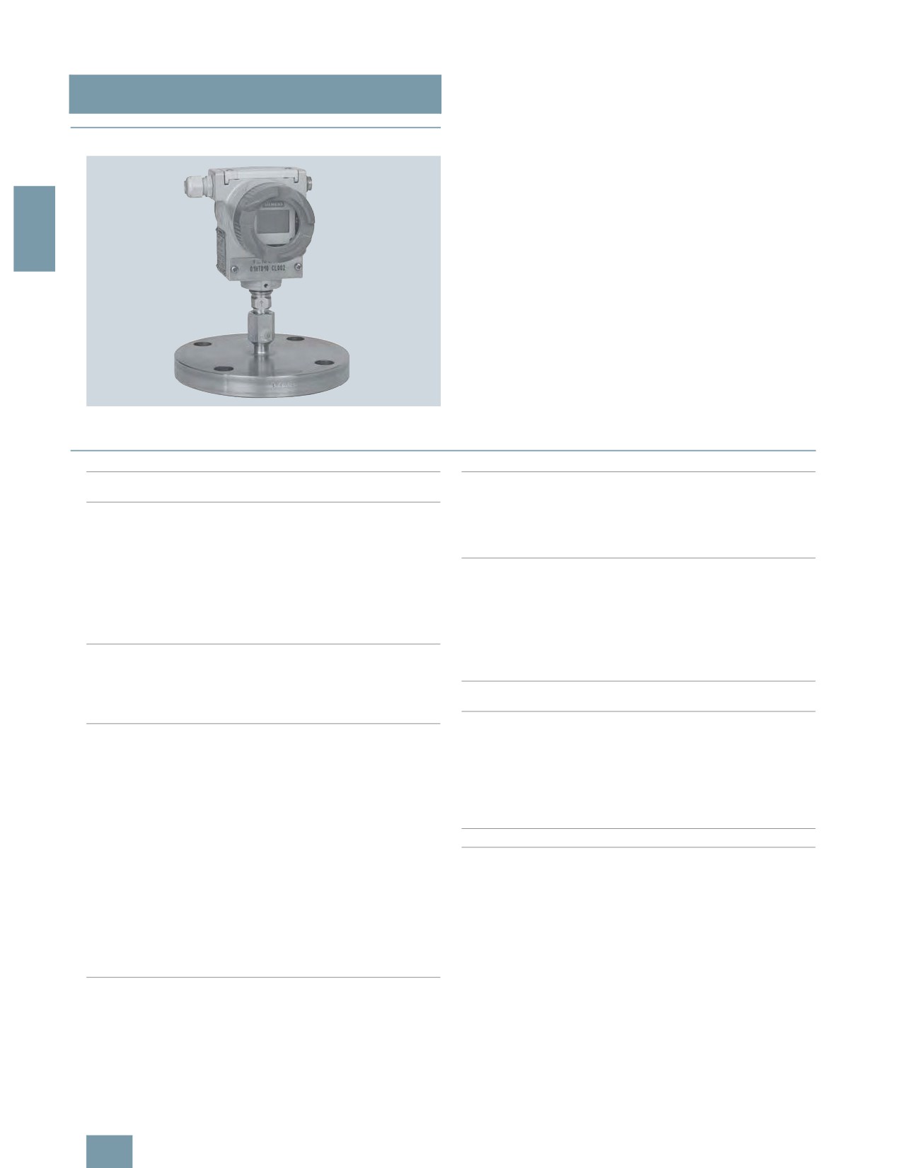
Diaphragm seals of flange design, directly fitted on a pressure transmitter
for pressure
■ Technical specifications
Diaphragm seals (flange design) for pressure and absolute pres-
Capillary
sure, directly fitted on a transmitter
• Length
Max. 10 m (32.8 ft), longer
Nominal diameter
Nominal pressure
lengths on request
• DN 50
PN 40, PN 100
• Internal diameter
2 mm (0.079 inch)
• DN 80
PN 40, PN 100
• Minimum bending radius
150 mm (5.9 inch)
• DN 100
PN 16, PN 40
Filling liquid
• Silicone oil M5
• 2 inch
Class 150, class 300, class 600,
• Silicone oil M50
class 1500
• High-temperature oil
• 3 inch
Class 150, class 300, class 600
• Halocarbon oil (for measuring
O2)
• 4 inch
Class 150, class 300, class 400
• Food oil (FDA listed)
Sealing face
• Glycerine/water (not suitable for
• For stainless steel, mat. No.
To EN 1092-1, form B1 or ASME
use in low-pressure range)
1.4404/316L
B16.5 RF 125 ... 250 AA
Max. recommended process
170 °C (338 °F)
• For the other materials
Smooth to EN 1092-1, form B2 or
temperature
ASME B16.5 RFSF
Permissible ambient temperature
Dependent on the pressure trans-
Materials
mitter and the filling liquid of the
remote seal.
• Main body
Stainless steel 316L
More information can be found in
• Wetted parts
Stainless steel 316L
the technical data of the pressure
transmitters and in the section
• Without foil
"Technical data of filling liquid" in
• PTFE (for vacuum on request)
the Technical description to the
remote seals.
• ECTFE (for vacuum on request)
Weight
Approx. 4 kg (8.82 lb)
• PFA (for vacuum on request)
Certificate and approvals
Monel 400, mat. No. 2.4360
Classification according to pressure
For gases of fluid group 1 and liq-
Hastelloy C276, mat. No. 2.4819
equipment directive (DRGL
uids of fluid group 1; complies
Hastelloy C4, mat. No. 2.4610
97/23/EC)
with requirements of article 3,
paragraph 3 (sound engineering
Tantalum
practice)
• Capillary
Stainless steel, 1.4571/316Ti
• Sealing material on the process
Copper
connection
Maximum pressure
See above and the technical data
of the transmitter
Tube length
• Without tube
• 50 mm (1.97 inch)
• 100 mm (3.94 inch)
• 150 mm (5.91 inch)
• 200 mm (7.87 inch)
2/164

SITRANS P measuring instruments for pressure
Diaphragm seals of flange design
For gage and absolute pressure,
directly fitted on transmitter
Selection and Ordering data
Order No. Ord.code
Selection and Ordering data
Order No. Ord.code
Diaphragm seal
D)
7MF491
0
-
Diaphragm seal
D) 7 M F 4 9 1 0 -
Directly fitted to a pressure transmitter
77777
7
7
7
Directly fitted to a pressure transmitter
77777
7
7
7
SITRANS P for pressure 7MF4037 and
SITRANS P for pressure 7MF4037 and
7MF4237 together with Order code "V01" (vac-
7MF4237 together with Order code "V01" (vac-
uum-proof design) and 7MF80271); must be
uum-proof design) and 7MF80271); must be
ordered separately
ordered separately
2
Process connection
Filling liquid
• Vertical (pressure transmitter upright)
0
• Silicone oil M5
1
• Silicone oil M50
2
• Horizontal
2
• High-temperature oil
3
Nominal diameter and nominal pressure
• Halocarbon oil (for measuring O2)
4
• DN 50
PN 40
A
• Glycerin/water3)
6
PN 100
B
• Food oil (FDA listed)
7
Other version
9
M
1
Y
• DN 80
PN 40
D
Add Order code and plain text:
PN 100
E
Filling liquid: ...
• DN 100
PN 16
G
1) With 7MF8027 and the measuring cells Q, S, T and U also order the vac-
PN 40
H
uum-tight version.
2) For vacuum on request.
• 2 inch
Class 150
L
3) Not suitable for use in low-pressure range.
Class 300
M
D) Subject to export regulations AL: N, ECCN: EAR99H.
Class 600
N
Class 1500
P
Selection and Ordering data
Order code
• 3 inch
Class 150
Q
Class 300
R
Further designs
Class 600
S
Please add "-Z" to Order No. and specify Order code.
• 4 inch
Class 150
T
Spark arrestor
A01
Class 300
U
With spark arrestor for mounting on zone 0 (including
Class 400
V
documentation) for transmitters for pressure and abso-
Smooth sealing face to DIN 1092-01, form B1 or
lute pressure
B2, or to ASME B16.5 125 ... 250 AA or RFSF
Quality inspection certificate (Factory calibration) to
C11
Other version
Z
J
1
Y
IEC 60770-2
Add Order code and plain text:
to IEC 60770-2
Nominal diameter: ...; Nominal pressure: ...
Acceptance test certificate
C12
Wetted parts materials
to EN 10204, section 3.1
• Stainless steel 316L
Vacuum-proof design
V01
- without foil
A
for use in low-pressure range for transmitters for
- with PTFE coating
E0
pressure
- with ECTFE coating2)
F
Calculation of span of associated pressure
Y05
- with PFA coating
D
transmitter
• Monel 400, mat. No. 2.4360
G
Enclose filled-in questionnaire with order
• Hastelloy C276, mat. No. 2.4819
J
• Hastelloy C4, mat. No. 2.4610
U
• Tantalum
K
Other version
Z
K
1
Y
Add Order code and plain text:
Wetted parts materials: ...
Tube length
• Without tube
0
• 50 mm
• (1.97 inch)
1
• 100 mm
• (3.94 inch)
2
• 150 mm
• (5.90 inch)
3
• 200 mm
• (7.87 inch)
4
Other version:
9
L
1
Y
Add Order code and plain text:
Tube length: ...
2/165

SITRANS P measuring instruments for pressure
Diaphragm seals of flange design
For gage and absolute pressure,
directly fitted on transmitter
Connection to EN 1092-1
■Dimensional drawings
Nom.
Nom.
b
D
d2
d4
d5
dM
f
k
n
diam. press.
G
mm
mm
mm
mm
mm
mm
mm
mm
DN 50
PN 40
20
165
18
102
48.3
59
2
125
4
2
PN 100 28
195
26
102
48.3
59
2
145
4
DN 80
PN 40
24
200
18
138
76
89
2
160
8
PN 100 32
230
26
138
76
89
2
180
8
=
DN 100 PN 16
20
220
18
158
94
89
2
180
8
PN 40
24
235
22
162
94
89
2
190
8
0
Connection to ASME B16.5
>
/
Nom. Nom.
b
D
d2
d4
d5
dM
f
k
n
- +
(
diam. press.
>
)
9
>,
lb/
mm
mm
mm
mm
mm
mm
mm
mm
sq.in.
>9
(inch)
(inch)
(inch)
(inch)
(inch)
(inch)
(inch)
(inch)
2 inch 150
20
150
20
92
48.3
59
1.6
120.5
4
+
(0.79)
(5.91)
(0.79)
(3.62)
(1.9)
(2.32)
(0.06)
(4.74)
300
22.5
165
20
92
48.3
59
1.6
127
8
=
0
(0.89)
(6.5)
(0.79)
(3.62)
(1.9)
(2.32)
(0.06)
(5)
600
32
165
20
92
48.3
59
6.4
127
8
(1.26)
(6.5)
(0.79)
(3.62)
(1.9)
(2.32)
(0.25)
(5)
1500
45
215
26
92
48.3
59
6.4
165
8
!4 &"
(1.77)
(8.46)
(1.02)
(3.62)
(1.9)
(2.32)
(0.25)
(6.5)
6
P
1 !4 5"
3 inch 150
24
190
20
127
76
89
1.6
152.5
4
(0.95)
(7.48)
(0.79)
(5)
(3)
(3.50)
(0.06)
(6)
300
29
210
22
127
76
89
1.6
168.5
8
Diaphragm seals of flange design, direct connection to a SITRANS P
pressure transmitter (process connection vertical (top) and horizontal
(1.14)
(8.27)
(0.87)
(5)
(3)
(3.50)
(0.06)
(6.63)
(bottom)), dimensions in mm (inch)
600
38.5
210
22
127
76
89
6.4
168.5
8
(1.52)
(8.27)
(0.87)
(5)
(3)
(3.50)
(0.25)
(6.63)
4 inch 150
24
230
20
158
94
89
1.6
190.5
8
(0.95)
(9.06)
(0.79)
(6.22)
(3.69)
(3.50)
(0.06)
(7.5)
300
32
255
22
158
94
89
1.6
200
8
(1.26)
(10.04)
(0.79)
(6.22)
(3.69)
(3.50)
(0.06)
(7.87)
400
41.5
255
26
158
94
89
6.4
200
8
(1.62)
(10.04)
(1.02)
(6.22)
(3.69)
(3.50)
(0.25)
(7.87)
d: Inside diameter of gasket according to EN 1092-1/
ASME B16.5
dM: Effective diaphragm diameter
2/166

SITRANS P measuring instruments for pressure
Diaphragm seals of flange design
For differential pressure,
fixed connection and with capillary
■Overview
2
Diaphragm seals of flange design for pressure transmitters for differential
pressure, fixed connection and with flexible capillary
■ Technical specifications
Diaphragm seals of flange design for pressure transmitters for dif-
Tube length
Without tube
ferential pressure, fixed connection and with flexible capillary
50 mm (1.97 inch)
Nominal diameter
Nominal pressure
100 mm (3.94 inch)
• DN 80
PN 40
150 mm (5.91 inch)
• DN 100
PN 16, PN 40
200 mm (7.87 inch)
• 3 inch
Class 150, class 300
Capillary
• 4 inch
Class 150, class 300
• Length
Max. 10 m (32.8 ft), longer
Sealing face
lengths on request
• For stainless steel, mat.
To EN 1092-1, form B1 or
• Internal diameter
2 mm (0.079 inch)
No. 1.4404/316L
ASME B16.5 RF 125 ... 250 AA
• Minimum bending radius
150 mm (5.9 inch)
• For the other materials
To EN 1092-1, form B2 or
Filling liquid
Silicone oil M5
ASME B16.5 RFSF
Silicone oil M50
Materials
High-temperature oil
• Main body
Stainless steel 316L
Halocarbon oil (for measuring O2)
• Wetted parts
Stainless steel 316L
Food oil (FDA listed)
• Without foil
Glycerine/water (not suitable for
• PTFE (for vacuum on request)
use in low-pressure range)
• ECTFE (for vacuum on request)
Max. recommended process
170 °C (338 °F)
temperature
• PFA (for vacuum on request)
Permissible ambient temperature
Dependent on the pressure trans-
Monel 400, mat. No. 2.4360
mitter and the filling liquid of the
remote seal
Hastelloy C276, mat. No. 2.4819
More information can be found in
Hastelloy C4, mat. No. 2.4610
the technical data of the pressure
Tantalum
transmitters and in the section
"Technical data of filling liquid" in
• Capillary
Stainless steel, mat.
the Technical description to the
No. 1.4571/316Ti
remote seals
• Sheath
Spiral hose made of stainless
Weight
Approx. 4 kg (8.82 lb)
steel, mat. No. 1.4301/316
Certificate and approvals
Sealing material in the process
flanges
Classification according to pressure
For gases of fluid group 1 and liq-
equipment directive (DRGL
uids of fluid group 1; complies
• For pressure transmitters, absolute
Copper
97/23/EC)
with requirements of article 3,
pressure transmitters and low-
paragraph 3 (sound engineering
pressure applications
practice)
• For other applications
Viton
Maximum pressure
See above and the technical data
of the pressure transmitter
2/167

SITRANS P measuring instruments for pressure
Diaphragm seals of flange design
For differential pressure,
fixed connection and with capillary
Selection and Ordering data
Order No. Ord. code
Selection and Ordering data
Order No. Ord. code
Diaphragm seal
D)
7MF4913 -
Diaphragm seal
D) 7 M F 4 9 1 3 -
Mounting flange (with tube as option) for
17777-7B
7
77
Mounting flange (with tube as option) for
17777-7B
7
7
7
direct mounting to high-pressure side and
direct mounting to high-pressure side and
flanged remote seal without tube, fitted by
flanged remote seal without tube, fitted by
means of capillary to low-pressure side of
means of capillary to low-pressure side of
2
SITRANS P for differential pressure, DS III series
SITRANS P for differential pressure, DS III series
(7MF4437)
(7MF4437)
Flange, connection to EN 1092-1
Length of capillary3)
Nom. diam.
Nom. press.
• 1.0 m
(3.28 ft)
2
• DN 80
PN 40
D
• 1.6 m
(5.25 ft)
3
• DN 100
PN 16
G
• 2.5 m
(8.20 ft)
4
PN 40
H
• 4.0 m
(13.1 ft)
5
Flange, connection to ASME B16.5
• 6.0 m
(19.7 ft)
6
Nom. diam.
Nom. press.
• 8.0 m
(26.25 ft)
7
• 10.0 m
(32.8 ft)
8
• 3 inch
Class 150
Q
Other version
9
N
1
Y
Class 300
R
Add Order code and plain text:
• 4 inch
Class 150
T
Length of capillary: ...
Class 300
U
1) For vacuum on request.
Other version
Z
J
1
Y
2) Not suitable for use in low-pressure range.
Add Order code and plain text:
3) Max. capillary length, see section "Technical description".
Flange: ..., Nominal diameter: ...; Nominal
pressure: ...
D) Subject to export regulations AL: N, ECCN: EAR99H.
Wetted parts materials
Selection and Ordering data
Order code
Smooth sealing face to EN 1092-1, form B1 or
B2, or to ASME B16.5 RF 125 ... 250 AA or RFSF
Further designs
• Stainless steel 316L
Please add "-Z" to Order No. and specify Order code.
- without foil
A
Spark arrestor
A02
- with PTFE coating
E0
With spark arrestor for mounting on zone 0 (including
- with ECTFE coating1)
F
documentation)
- with PFA coating
D
Quality inspection certificate (Factory calibration) to
C11
IEC 60770-2
• Monel 400, mat. No. 2.4360
G
• Hastelloy C276, mat. No. 2.4819
J
Acceptance test certificate
C12
• Hastelloy C4, mat. No. 2.4610
U
to EN 10204, section 3.1
• Tantalum
K
Vacuum-proof design
V03
Other version
Z
K
1
Y
for use in low-pressure range
Add Order code and plain text:
Calculation of span of associated pressure
Y05
Wetted parts materials: ...
transmitter
Tube length
Enclose filled-in questionnaire with order
(for mounting flange on high-pressure side)
• Without tube
0
• 50 mm
(1.97 inch)
1
• 100 mm
(3.94 inch)
2
• 150 mm
(5.90 inch)
3
• 200 mm
(7.87 inch)
4
Other version:
9
L
1
Y
Add Order code and plain text:
Tube length: ...
Filling liquid
• Silicone oil M5
1
• Silicone oil M50
2
• High-temperature oil
3
• Halocarbon oil (for measuring O2)
4
• Glycerin/water2)
6
• Food oil (FDA listed)
7
Other version
9
M
1
Y
Add Order code and plain text:
Filling liquid: ...
2/168

SITRANS P measuring instruments for pressure
Diaphragm seals of flange design
For differential pressure,
fixed connection and with capillary
Connection to EN 1092-1
■Dimensional drawings
Nom.
Nom.
b
D d2
d4
d5
dM
f
k
n
diam. press.
9
+
mm
mm mm mm
mm
mm
mm
mm
0
;
DN 80
PN 40
24
200
18
138
76
89
2
160
8
=
DN 100 PN 16
20
200
18
158
94
89
2
180
8
2
PN 40
24
235
22
162
94
89
2
190
8
Connection to ASME B16.5
Nom.
Nom. b
D
d2
d4
d5
dM
f
k
n
diam. press.
lb/
mm mm mm mm mm mm mm mm
sq.in.
(inch)
(inch)
(inch)
(inch)
(inch)
(inch)
(inch)
(inch)
3 inch
150
24
190
20
127
76
89
1,6
152,5
4
(0.96)
(7.48)
(0.79)
(5)
(3)
(3.50)
(0.06)
(6)
300
29
210
22
127
76
89
1,6
168,5
8
+
(1.14)
(8.27)
(0.87)
(5)
(3)
(3.50)
(0.06)
(6.63)
4 inch
150
24
230
20
158
94
89
1,6
190,5
4
=
0
(0.95)
(9.06)
(0.79)
(6.22)
(3.69)
(3.50)
(0.06)
(7)
300
32
255
22
158
94
89
1,6
200
8
(1.26)
(10.04)
(0.87)
(6.22)
(3.69)
(3.50)
(0.06)
(7.87)
d: Inside diameter of gasket according to EN 1092-1 /
ASME B16.5
- +
(
!& 5)"
dM: Effective diaphragm diameter
Diaphragm seals of flange design with flexible capillary, fixed connec-
tion, for connection to a SITRANS P pressure transmitter for differential
pressure, dimensions in mm (inch)
2/169

SITRANS P measuring instruments for pressure
Quick-release diaphragm seals
For gage, absolute and differential pressure
- DN 65
PN
25
■Overview
- DN 80
PN
25
• Clamp connection
-
1½ inch
PN
40
-
2 inch
PN
40
2
-
2½ inch
PN
25
-
3 inch
PN
25
For differential pressure and flow
• To DIN 11851 with slotted union nut
- DN 50
PN
25
- DN 65
PN
25
- DN 80
PN
25
• To DIN 11851 with threaded socket
- DN 50
PN
25
- DN 65
PN
25
- DN 80
PN
25
Quick-release diaphragm seals, to DIN 11851 with slotted union nut
• Clamp connection
-
2 inch
PN
40
-
2½ inch
PN
25
-
3 inch
PN
25
Sealing face
• For stainless steel, mat. No.
To EN 1092-1, form B1 or
1.4404/316L
ASME B 16.5RF 125 ... 250 AA
• For the other materials
To EN 1092-1, form B2 or
ASME B16.5 RFSF
Materials
• Main body
Stainless steel 316L
• Wetted parts
Stainless steel 316L
• Capillary
Stainless steel, mat.
Quick-release diaphragm seals, with clamp connection
No. 1.4571/316Ti
Quick-release diaphragm seals are available for the following
• Sheath
Spiral hose made of stainless
SITRANS P pressure transmitter series:
steel, mat. No. 1.4301/316
• For pressure: MK II, DS III, DS III PA, DS III FF
Maximum pressure
See above and the technical data
• For differential pressure and flow: DS III, DS III PA, DS III FF
of the pressure transmitter
The quick-release remote seals are common designs in the food
Tube length
Without tube
industry. Their design means that the measured medium cannot
Capillary
accumulate in dead volumes. The quick-release clamp present
on the remote seal means that quick dismounting is possible for
• Length
Max. 10 m (32.8 ft), longer
lengths on request
cleaning.
• Internal diameter
2 mm (0.079 inch)
■ Technical specifications
• Minimum bending radius
150 mm (5.9 inch)
Quick-release diaphragm seal
Filling liquid
Food oil (FDA listed)
Connection, nominal diameter
Nominal pressure
Glycerin/water (not suitable for
For pressure
use in low-pressure range)
• To DIN 11851 with slotted union nut
Permissible ambient temperature
Dependent on the pressure trans-
mitter and the filling liquid of the
- DN 25
PN 40
remote seal
- DN 32
PN 40
More information can be found in
the technical data of the pressure
- DN 40
PN 40
transmitters and in the section
- DN 50
PN 25
"Technical data of filling liquid" in
the Technical description to the
- DN 65
PN 25
remote seals
- DN 80
PN 25
Weight
Approx. 4 kg (8.82 lb)
• To DIN 11851 with threaded socket
Certificates and approvals
- DN 25
PN 40
Classification according to pressure
For gases of fluid group 1 and liq-
equipment directive
uids of fluid group 1; complies
- DN 32
PN 40
(DRGL 97/23/EC)
with requirements of article 3,
- DN 40
PN 40
paragraph 3 (sound engineering
practice)
- DN 50
PN 25
2/170

SITRANS P measuring instruments for pressure
Quick-release diaphragm seals
For gage, absolute and differential pressure
Selection and Ordering data
Order No. Ord. code
Selection and Ordering data
Order No. Ord. code
Quick-release diaphragm seal
D)
7MF4940 -
Quick-release diaphragm seal
D)
7MF4943 -
for SITRANS P pressure transmitters for
77A07-
7B
7
7
7
for SITRANS P pressure transmitters for pres-
77A07-7B
7
7
7
pressure 7MF4037 and 7MF4237 together with
sure for differential pressure and flow, type
Order code "V01" (vacuum-proof design) and
7MF4437; order separately
7MF80271); must be ordered separately
Filling liquid: Food oil (FDA listed)
Filling liquid: Food oil (FDA listed)
Material: Stainless steel, mat. No. 1.4435
2
Material: Stainless steel, mat. No. 1.4435
Delivery unit: 2 off
Nom. diam.
Nom. press.
Nom. diam.
Nom. press.
• Connection to DIN 11851 with slotted union nut
• Connection to DIN 11851 with slotted union nut
- DN 25
PN 40
1B
- DN 50
PN 25
1E
- DN 32
PN 40
1C
- DN 65
PN 25
1F
- DN 40
PN 40
1D
- DN 80
PN 25
1G
- DN 50
PN 25
1E
• Connection to DIN 11851 with threaded
- DN 65
PN 25
1F
socket
- DN 80
PN 25
1G
- DN 50
PN 25
2E
• Connection to DIN 11851 with screw necks
- DN 65
PN 25
2F
- DN 25
PN 40
2B
- DN 80
PN 25
2G
- DN 32
PN 40
2C
• Clamp connection
- DN 40
PN 40
2D
-
2 inch
PN 40
4M
- DN 50
PN 25
2E
-
2½ inch
PN 40
4N
- DN 65
PN 25
2F
-
3 inch
PN 40
4P
- DN 80
PN 25
2G
Other version
• Clamp connection
Add Order codes and plain text:
-
1½ inch
PN 40
4L
Nominal diameter: ...
9
H
1
Y
-
2 inch
PN 40
4M
Nominal pressure: ...
Z
J
1
Y
-
2½ inch
PN 40
4N
Filling liquid
-
3 inch
PN 40
4P
• Glycerin/water1)
6
Other version
• Food oil (FDA listed)
7
Add Order codes and plain text:
Other version
9
M
1
Y
Nominal diameter: ...
9
H
1
Y
Add Order code and plain text:
Nominal pressure: ...
Z
J
1
Y
Filling liquid: ...
Filling liquid
Connection to transmitter
• Glycerin/water2)
6
through capillary, Length:2)
• Food oil (FDA listed)
7
• 1.0 m
(3.28 ft)
2
Other version
9
M
1
Y
• 1.6 m
(5.25 ft)
3
Add Order code and plain text:
• 2.5 m
(8.20 ft)
4
Filling liquid: ...
• 4.0 m
(13.1 ft)
5
Connection to pressure transmitter
• 6.0 m
(19.7 ft)
6
• direct
0
• 8.0 m
(26.25 ft)
7
through capillary, length:3)
• 10.0 m
(32.8 ft)
8
• 1.0 m
(3.28 ft)
2
Other version
9
N
1
Y
Add Order code and plain text:
• 1.6 m
(5.25 ft)
3
Length of capillary: ...
• 2.5 m
(8.20 ft)
4
• 4.0 m
(13.1 ft)
5
Further designs
Order code
• 6.0 m
(19.7 ft)
6
Please add "-Z" to Order No. and specify Order
• 8.0 m
(26.25 ft)
7
code.
• 10.0 m
(32.8 ft)
8
Quality inspection certificate (Factory cali-
C11
Other version
9
N
1
Y
bration) to IEC 60770-2
Add Order code and plain text:
Acceptance test certificate
C12
Length of capillary: ...
to EN 10204, section 3.1
Further designs
Order code
Please add "-Z" to Order No. and specify Order
Vacuum-proof design
V03
code.
for use in low-pressure range
Quality inspection certificate (Factory cali-
C11
1) Not suitable for use in low-pressure range.
bration) to IEC 60770-2
2)
Max. capillary length, see section "Technical description"
Acceptance test certificate
C12
D) Subject to export regulations AL: N, ECCN: EAR99H.
to EN 10204, section 3.1
Vacuum-proof design
V01
for use in low-pressure range
1) With 7MF8027 and the measuring cells Q, S, T and U also order the
vacuum-tight version.
2) Not suitable for use in low-pressure range.
3) Max. capillary length, see section "Technical description"
D) Subject to export regulations AL: N, ECCN: EAR99H.
2/171

SITRANS P measuring instruments for pressure
Quick-release diaphragm seals
For gage, absolute and differential pressure
■Dimensional drawings
2
;
;
97
;
97
@
97
9
9
@
;
- *7
0
;
97
;
;
97
@
97
9
9
@
;
- *7
0
00
0
Clamp connection (left)
Connection to DIN 11851 with slotted
Connection to DIN 11851 with
union nut (center)
threaded socket (right)
DN
ØdM
ØD
H
DN Ø dM Ø D H
G1
DN Ø dM H
G1
(1½ inch)
32
(1.26)
50,5
(2)
35
(1.38)
25
25
63
36
Rd 52x1/6
25
25
36
Rd 52x1/6
(2 inch)
40
(1.57)
64
(2.52)
35
(1.38)
32
32
70
36
Rd 52x1/6
32
32
36
Rd 52x1/6
(2½ inch)
52
(2.05)
77,5
(3.05)
35
(1.38)
40
40
78
36
Rd 65x1/6
40
40
36
Rd 65x1/6
(3 inch)
72
(2.83)
91
(3.58)
35
(1.38)
50
52
112
36
Rd 78x1/6
50
52
36
Rd 78x1/6
65
65
112
36
Rd 95x1/6
65
65
36
Rd 95x1/6
80
72
127
36
Rd 110x1/6
80
72
36
Rd 110x1/6
25
25
63
36
Rd 52x1/6
dM Effective diaphragm diameter
Quick-release diaphragm seal, dimensions in mm (inch)
2/172
SITRANS P measuring instruments for pressure
Miniature diaphragm seal
For gage and absolute pressure
■Overview
■ Technical specifications
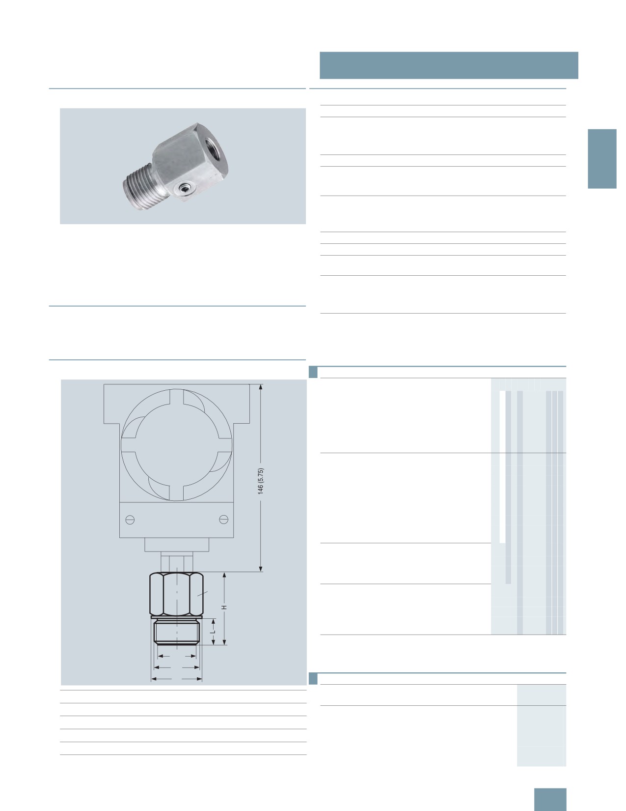
Miniature diaphragm seals
Span with
• G1B
> 6 bar (> 87 psi)
• G1½B
> 2 bar (> 29 psi)
• G2B
> 600 mbar (> 8.7 psi)
2
Filling liquid
Silicone oil M5 or food oil (FDA listed)
Material
• Main body
Stainl. steel mat No. 1.4404/ 316L
• Diaphragm
Stainl. steel mat No. 1.4404 / 316L
Maximum pressure
100% of nominal pressure of pressure
transmitter, up to maximum of PN 400
(5802 psi) (depending on the seal
used)
Miniature diaphragm seals
Temperature of use
Same as pressure transmitter
The miniature diaphragm seals are available for the following
Temperature range of medium Same as pressure transmitter
SITRANS P pressure transmitter series for pressure:
Max. recommended process
150 °C (302 °F)
• P300, DS III, DS III PA, DS III FF
temperature
Suitable for high pressures, contaminated, fibrous and viscous
Weight
media in the chemical, paper, food and drink industries.
• G1B
Approx. 0.3 kg (approx. 0.66 lb)
• G1½B
Approx. 0.5 kg (approx. 1.10 lb)
• G2B
Approx. 0.8 kg (approx. 1.76 lb)
■Design
Certificate and approvals
• Flush-mounted diaphragm
Classification according to
For gases of fluid group 1 and liquids
• No dead spaces
pressure equipment directive
of fluid group 1; complies with
• Fixed threaded stems
(DRGL 97/23/EC)
requirements of article 3, para-
graph 3 (sound engineering practice)
■Dimensional drawings
Selection and Ordering data
Order No. Ord. code
Miniature diaphragm seals
D) 7 M F 4 9 6 0 -
directly fitted to SITRANS P pressure transmitters
17707
777
for pressure; type, 7MF4037 and 7MF4237
together with Order code "V01" (vacuum-proof
design) and 7MF80271); must be ordered sepa-
rately
Material: Stainless steel, mat. No. 1.4401
Pressure rating, see "Pressure transmitters"
Process connection
• G1B
C
• G1½B
D
• G2B
E
• 1“ - NPT
K
• 1½“ - NPT
L
• 2“ - NPT
M
Other version, add Order code and plain text:
Z
J
1
Y
Process connection: ...
Wetted parts materials
• Stainless steel 316L
A
Other version, add Order code and plain text:
Z
K
1
Y
Wetted parts materials: ...
A
Filling liquid
• Silicone oil M5
1
• Food oil (FDA listed)
7
Other version, add Order code and plain text:
9
M
1
Y
Filling liquid: ...
1) With 7MF8027 and the measuring cells Q, S, T and U also order the
vacuum-tight version.
;
D) Subject to export regulations AL: N, ECCN: EAR99H.
@
Selection and Ordering data
Order code
Further designs
G
Ø dM
SW
Ø d
L
H
Please add "-Z" to Order No. and specify Order code.
mm
(inch)
mm (inch) mm (inch)
mm (inch)
mm (inch)
Quality inspection certificate (Factory calibration) to C11
G1B
25
(0.98)
41
(1.61)
39
(1.53)
28
(1.1)
56
(2.21)
IEC 60770-2
Acceptance test certificate
C12
G1½B
40
(1.57)
55
(2.17)
60
(2.36)
30
(1.18)
50
(1.97)
to EN 10204, section 3.1
G2B
50
(1.97)
60
(2.36)
70
(2.76)
30
(1.18)
63
(2.48)
V01
Vacuum-proof design
for use in low-pressure range
dM: Effective diaphragm diameter
Miniature diaphragm seal, dimensions in mm (inch)
2/173
SITRANS P measuring instruments for pressure
Flushing rings
For diaphragm seals
■Overview
■ Technical specifications
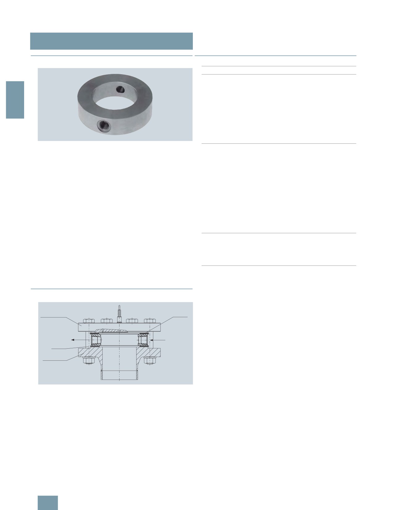
Flushing ring for remote seals of sandwich and flange design
Nominal diameter
Nominal pressure
• DN 50
PN 16 ... PN 100
2
• DN 80
PN 16 ... PN 100
• DN 100
PN 16 ... PN 100
• DN 125
PN 16 ... PN 100
• 2 inch
Class 150 ... class 600
• 3 inch
Class 150 ... class 600
• 4 inch
Class 150 ... class 600
• 5 inch
Class 150 ... class 600
Flushing ring
Sealing face
Flushing rings are required for flange-mounted and sandwich-
• To EN 1092-1
Form B1
type remote seals (Order No. 7MF4900 ... 7MF4923) if the dan-
Form B2
ger exists that the process conditions and the geometry of the
connection could cause the medium to form deposits or block-
Form D/Form D
ages.
Form C/Form C
The flushing ring is clamped between the process flange and
Form C/Form C
the remote seal.
Form E
Deposits can be flushed away from the diaphragm through the
Form F
holes in the side, or the pressure volume can be vented. Different
nominal diameters and forms permit adaptation to the respec-
• To ASME B16.5
RF 125 ... 250 AA
tive process flange.
RFSF
Process connection
RJT ring groove
For flanges to EN and ASME:
Flushing holes (2 off), female
• G¼
thread:
DN 50, 80, 100, 125; PN 16 ... 100 or
• G½
DN 2 inch, 3 inch, 4 inch, 5 inch; Class 150 ... 600
• ¼-18 NPT
Standard design
• ½-14 NPT
Material: CrNi-Stahl, mat. No. 1.4404/316L
Material
Stainless steel 1.4404/316L
Sealing faces and flushing holes: See Selection and Ordering
data
■Design
0
'
(
'
(
'
(
@
,
;
0
Installation example
2/174

SITRANS P measuring instruments for pressure
Flushing rings
For diaphragm seals
Selection and Ordering data
Order No. Ord. code
■Dimensional drawings
Flushing ring
D)
7MF492
5
-
for remote seals 7MF4900 to 7MF4923
17777
7
7
7
Nom. diam.
Nom. press.
• DN 50
PN 16 ... PN 100
A
• DN 80
PN 16 ... PN 100
B
2
• DN 100
PN 16 ... PN 100
C
• DN 125
PN 16 ... PN 100
D
• 2 inch
Class 150 ... 600
G
)
• 3 inch
Class 150 ... 600
H
• 4 inch
Class 150 ... 600
J
• 5 inch
Class 150 ... 600
K
Connection to EN 1092-1
Other version
Z
J
1
Y
DN
PN
d4
di
h
Weight
Add Order code and plain text:
Nominal diameter: ...; Nominal pressure: ...
(mm)
(bar)
(mm)
(mm)
(mm)
(kg)
Sealing face
50
16 ... 100
102
62
30
1.10
• EN 1092-1
80
16 ... 100
138
92
30
1.90
- Form B1
A
- Form B2
C
100
16 ... 100
162
92
30
3.15
- Form C/Form C
D
125
16 ... 100
188
126
30
3.50
- Form D/Form C
E
Connection to ASME B 16.5
- Form D/Form D
F
DN Class
d4
di
h
Weight
- Form E
G
- Form F
H
inch
mm
(inch) mm
(inch)
mm (inch)
kg
(lb)
• ASME B16.5
2
150 ... 600
92
(3.62)
62
(2.44)
30
(1.18)
0.60
(1.32)
- RF 125 ... 250 AA
M
3
150 ... 600
127
(5)
92
(3.62)
30
(1.18)
1.05
(2.31)
- RFSF
Q
- RJT ring groove
R
4
150 ... 600
157
(6.18)
92
(3.62)
30
(1.18)
2.85
(6.28)
Other version
Z
K
1
Y
5
150 ... 600
185.5
(7.3)
126
(4.96)
30
(1.18)
3.30
(7.28)
Add Order code and plain text:
Sealing face: ...
Flushing ring, dimension drawing
Flushing holes (2 off)
• Female thread G¼
1
• Female thread G½
2
• Female thread ¼-18 NPT
3
• Female thread ½-14 NPT
4
Material
• Stainless steel 316L
0
Other version
9
M
1
Y
Add Order code and plain text:
Material: ...
Selection and Ordering data
Order code
Further designs
Please add "-Z" to Order No. and specify Order code.
Acceptance test certificate
C12
to EN 10204, section 3.1
D) Subject to export regulations AL: N, ECCN: EAR99H.
2/175

SITRANS P measuring instruments for pressure
Clamp-on seals of flange design
For gage pressure, differential pressure and flow
■Overview
■ Technical specifications
Clamp-on seals for flange-mounting
Nominal diameter
Nominal pressure
• DN 25
PN 6 ... PN 100
2
• DN 40
PN 6 ... PN 100
• DN 50
PN 6 ... PN 100
• DN 80
PN 6 ... PN 100
• DN 100
PN 6 ... PN 100
• 1 inch
Class 150 ... class 2500
• 1½ inch
Class 150 ... class 2500
• 2 inch
Class 150 ... class 2500
• 3 inch
Class 150 ... class 2500
• 4 inch
Class 150 ... class 2500
Process connection
Flange to EN 1092-1 or
ASME B 16.5
Sealing face
To EN 1092-1, form B1 or to
Clamp-on seals for flange-mounting
ASME B16.5 RF 125 ... 250 A or
The clamp-on seal is completely integrated in the process line.
RFSF
It is particularly suitable for flowing and highly viscous media.
Materials
The clamp-on remote seal consists of a cylindrical jacket into
• Main body
Stainless steel 1.4404/316L
which a thin-walled pipe is welded. It is clamped directly be-
• Diaphragm
Stainless steel 1.4404/316L
tween two flanges in the pipeline.
• Wetted parts
Stainless steel 1.4404/316L
■Design
• Without foil
• Clamp-on seals for flange-mounting (flange design) to
• ECTFE coating
EN/ASME for SITRANS P pressure transmitters
• PFA coating (for vacuum on re-
- For pressure: P300, DS III, DS III PA and DS III FF series
quest)
- For differential pressure and flow: DS III, DS III PA and
Monel 400, mat. No. 2.4360
DS III FF
Hastelloy C276, mat. No. 2.4819
• Sealing face to EN 1092-1 or ASME B16.5
• Connection to the transmitter directly or by means of a flexible
Hastelloy C4, mat. No. 2.4610
capillary (max. 10 m long)
Tantalum
• See Technical data for details of materials used for the wetted
• Capillary
Stainless steel, mat.
parts
No. 1.4571/316Ti
• Material used for the capillary, the guard sleeve, the seal’s
• Sheath
Spiral hose made of stainless
main body and the measuring cell: Stainless steel,
steel, mat. No. 1.4301/316
mat.-No. 1.4571
Capillary
• Filling liquid: Silicone oil, high-temperature oil, halocarbon oil,
• Length
Max. 10 m (32.8 ft)
food oil (FDA listed) or glycerin/water (not suitable for uses in
low-pressure range)
• Internal diameter
2 mm (0.079 inch)
• Minimum bending radius
150 mm (5.9 inch)
Filling liquid
Silicone oil M5
■Function
Silicone oil M50
The measured pressure is transferred from the diaphragm to the
High-temperature oil
filling liquid and passes either directly or through the capillary to
Halocarbon oil
the measuring chamber of the pressure transmitter. The interior
of the diaphragm seal and of the capillary, as well as the mea-
Food oil (FDA listed)
suring chamber of the pressure transmitter, are filled gas-free by
Glycerin/water (not suitable for
the filling liquid.
uses in low-pressure range)
Note:
Permissible ambient temperature
See pressure transmitters, see fill-
ing liquid
When operating in the low-pressure range, also during commis-
Weight
Approx. 4 kg (8.82 lb)
sioning, it is recommended to use a vacuum-proof remote seal
(see Selection and Ordering data).
Certificates and approvals
Classification according to pressure
For gases of fluid group 1 and liq-
equipment directive
uids of fluid group 1; complies
(DRGL 97/23/EC)
with the requirements of article 3,
paragraph 1 (appendix 1);
assigned to category III, confor-
mity evaluation module H by the
TÜV Nord
2/176

SITRANS P measuring instruments for pressure
Clamp-on seals of flange design
For gage pressure, differential pressure and flow
Selection and Ordering data
Order No. Ord. code
Selection and Ordering data
Order code
Clamp-on seal for flange-mounting for
Further designs
SITRANS P pressure transmitters
Please add "-Z" to Order No. and specify Order code.
for pressure
D)
7MF4980 -
Spark arrestor
7MF4037 and 7MF4237 together with Order
With spark arrestor for mounting on zone 0 (including
code "V01" (vacuum-proof design) and
documentation)
7MF80271); must be ordered separately, scope
2
of delivery: 1 off
• Pressure and absolute pressure
A01
for differential pressure and flow
D)
7MF4983 -
• for differential pressure transmitters
A02
7MF4433 or 7MF4434; order separately, scope
Quality inspection certificate (Factory calibration) to
C11
of delivery: 1 pair (set); Material: Completely of
IEC 60770-2
stainless steel, mat. No. 1.4404/316L;
Process connection to EN 1092-1 or ASME
Acceptance test certificate
C12
B16.5; sealing face to EN 1092-1, form B1,
To EN 10204, section 3.1
or to ASME B16.5 RF 125 ... 250 AA
Vacuum-proof design
V01
17707-7B
7
77
For use in low-pressure range
Nominal diameter and nominal pressure
Calculation of span of associated pressure trans-
Y05
• DN 25
PN 6 ... 100
B
mitter
• DN 40
PN 6 ... 100
D
Enclose filled-in questionnaire with order
• DN 50
PN 6 ... 100
E
Note:
• DN 80
PN 6 ... 100
G
Suffix "Y01" required with pressure transmitter!
• DN 100
PN 6 ... 100
H
D) Subject to export regulations AL: N, ECCN: EAR99H.
• 1 inch
Class 150 ... 2500
L
• 1½ inch
Class 150 ... 2500
M
• 2 inch
Class 150 ... 2500
N
• 3 inch
Class 150 ... 2500
P
• 4 inch
Class 150 ... 2500
Q
Other version
Z
J
1 Y
Add Order code and plain text:
Nominal diameter: ...; Nominal pressure: ...
Wetted parts materials
• Stainless steel 316L
- Without foil
A
- With PFA coating
D
- With ECTFE coating2)
F
• Monel 400, mat. No. 2.4360
G
• Hastelloy C276, mat. No. 2.4819
J
• Hastelloy C4, mat. No. 2.4610
U
• Tantalum
K
Other version
Z
K
1
Y
Add Order code and plain text:
Wetted parts materials: ...
Filling liquid
• Silicone oil M5
1
• Silicone oil M50
2
• High-temperature oil
3
• Halocarbon oil (for measuring O2)
4
• Glycerin/water3)
6
• Food oil (FDA listed)
7
Other version
9
M
1
Y
Add Order code and plain text:
Filling liquid: ...
Connection to transmitter
• direct (only for 7MF4980)
0
through capillary, length:4)
• 1.0 m
(3.28 ft)
2
• 1.6 m
(5.25 ft)
3
• 2.5 m
(8.20 ft)
4
• 4.0 m
(13.1 ft)
5
• 6.0 m
(19.7 ft)
6
• 8.0 m
(26.25 ft)
7
• 10.0 m
(32.8 ft)
8
Other version
9
N
1
Y
Add Order code and plain text:
Length of capillary: ...
1) With 7MF8027 and the measuring cells Q, S, T and U also order the
vacuum-tight version.
2) For vacuum on request.
3) Not suitable for use in low-pressure range.
4) Max. capillary length, see section "Technical description"
2/177

SITRANS P measuring instruments for pressure
Clamp-on seals of flange design
For gage pressure, differential pressure and flow
Connection to EN 1092-1
■Dimensional drawings
DN
PN
D
Mb
L
H
mm
bar
mm
mm
mm
mm
25
6 ... 100
63
28,5
60
78.5
40
6 ... 100
85
43
60
89.5
2
50
6 ... 100
95
54.5
60
92.5
)1 !/ 2/"
80
6 ... 100
130
82.5
60
112
100
6 ... 100
150
107
60
122
Connection to ASME B16.5
DN
Class
D
Mb
L
H
(inch)
mm
mm
mm
mm
(inch)
(inch)
(inch)
(inch)
6
1
150 ... 2500
63
28.5
60
78.5
(2.48)
(1.12)
(2.36)
(3.1)
1½
150 ... 2500
85
43
60
86
(3.35)
(1.69)
(2.36)
(3.4)
2
150 ... 2500
95
54.5
60
94.5
> ;+
(3.74)
(2.15)
(2.36)
(3.72)
9
3
150 ... 2500
130
82.5
60
112
(5.12)
(3.25)
(2.36)
(4.4)
4
150 ... 2500
150
107
60
122
(5.9)
(4.21)
(2.36)
(4.8)
/ .. !/ 5"
Clamp-on seal for flange-mounting, connected to SITRANS P pressure
transmitter, dimensions in mm (inch)
2/178

SITRANS P measuring instruments for pressure
Quick-release clamp-on seals
For pressure and absolute pressure
■Overview
■Function
The measured pressure is transferred from the diaphragm,
mounted on the inner circumference of the clamp-on seal, to the
filling liquid and then passes through the capillary to the measur-
ing chamber of the pressure transmitter. The interior of the
clamp-on seal and of the capillary, as well as the measuring
2
chamber of the pressure transmitter, are filled gas-free by the fill-
ing liquid.
Note:
When operating in the low-pressure range, also during commis-
sioning, it is recommended to use a vacuum-proof pressure
transmitter (see Selection and Ordering data).
■ Technical specifications
Clamp-on seals of quick-release design for pressure
Connection
Nominal
Nominal
diameter
pressure
• To DIN 11851 with threaded
DN 25
PN 40
Quick-release clamp-on seals, to DIN 11851 with threaded socket
socket
DN 40
PN 40
DN 50
PN 25
DN 65
PN 25
DN 80
PN 25
DN 100
PN 25
• Clamp connection
1½ inch
PN 40
2 inch
PN 40
2½ inch
PN 40
3 inch
PN 40
Material
• Main body
Stainless steel 1.4404/316L
• Diaphragm
Stainless steel 1.4404/316L
Capillary
• Length
Max. 10 m (32.8 ft)
Quick-release clamp-on seals, with clamp connection
• Internal diameter
2 mm (0.079 inch)
Quick-release clamp-on seals for pressure are available for the
• Minimum bending radius
150 mm (5.9 inch)
following SITRANS P pressure transmitter series:
Filling liquid
• Food oil (FDA listed)
• P300
• Glycerin/water (not suitable for
• DS III
use in low-pressure range)
• DS III PA
Permissible ambient temperature
Dependent on the pressure trans-
mitter and the filling liquid of the
• DS III FF
remote seal
More information can be found in
■Application
the technical data of the pressure
transmitters and in the section
The quick-release clamp-on seal is a special design for flowing
"Technical data of filling liquid" in
media and high-viscosity media. Since it is completely inte-
the Technical description to the
grated in the process pipe, no turbulences, dead volumes or
remote seals
other obstructions to the flow occur. The measured medium
Weight
Approx. 4 kg (approx. 8.82 lb)
flows unhindered through the clamp-on seal and results in self-
Certificate and approvals
cleaning of the measuring chamber. Furthermore, the clamp-on
seal can be cleaned by a pig.
Classification according to pres-
For gases of fluid group 1 and liq-
sure equipment directive
uids of fluid group 1; complies with
(DRGL 97/23/EC)
the requirements of article 3,
■Design
paragraph 1 (appendix 1);
assigned to category III, confor-
The quick-release clamp is available in two versions:
mity evaluation module H by the
• DIN 11851 with threaded socket
TÜV Nord
• Clamp connection
The clamp-on seal is connected to the pressure transmitter ei-
ther directly or by way of a capillary.
2/179

SITRANS P measuring instruments for pressure
Quick-release clamp-on seals
For pressure and absolute pressure
Selection and Ordering data
Order No. Ord. code
Quick-release clamp-on seal
D)
7MF4950 -
for SITRANS P pressure transmitters for
77A07-
7B
7
7
7
pressure
7MF4037 and 7MF4237 together with Order
code "V01" (vacuum-proof design) and
2
7MF80271); must be ordered
separately
Filling liquid: Food oil (FDA listed)
Material: Stainless steel 316L
Nom. diam.
Nom. press.
• Connection to DIN 11851 with screw necks
- DN 25
PN 40
2B
- DN 40
PN 40
2D
- DN 50
PN 25
2E
- DN 65
PN 25
2F
- DN 80
PN 25
2G
- DN 100
PN 25
2H
• Clamp connection
-
1½ inch
PN 40
4L
-
2 inch
PN 40
4M
-
2½ inch
PN 40
4N
-
3 inch
PN 40
4P
Other version
Add Order codes and plain text:
Nominal diameter: ...
9
H
1
Y
Nominal pressure: ...
Z
J
1
Y
Filling liquid
• Glycerin/water2)
6
• Food oil (FDA listed)
7
Other version
9
M
1
Y
Add Order code and plain text:
Filling liquid: ...
Connection to transmitter
• Direct
0
Through capillary, length:3)
• 1.0 m
(3.28 ft)
2
• 1.6 m
(5.25 ft)
3
• 2.5 m
(8.20 ft)
4
• 4.0 m
(13.1 ft)
5
• 6.0 m
(19.7 ft)
6
• 8.0 m
(26.25 ft)
7
• 10.0 m
(32.8 ft)
8
Other version
9
N
1
Y
Add Order code and plain text:
Length of capillary: ...
1) With 7MF8027 and the measuring cells Q, S, T and U also order the vac-
uum-tight version.
2) Not suitable for use in low-pressure range.
3) Max. capillary length, see section "Technical description"
D) Subject to export regulations AL: N, ECCN: EAR99H.
Selection and Ordering data
Order code
Further designs
Please add "-Z" to Order No. and specify Order code.
Quality inspection certificate (Factory calibration) to C11
IEC 60770-2
Acceptance test certificate
C12
to EN 10204, section 3.1
Vacuum-proof design
V01
for use in low-pressure range
2/180

SITRANS P measuring instruments for pressure
Quick-release clamp-on seals
For pressure and absolute pressure
■Dimensional drawings
2
,
!!
> (=
1
4
,
!
> (=
1
4
! 44
!4
Connection to DIN 11851 with screw necks
Clamp connection for pipes to BS 4825/3 and o.D. tubes
DN Ø D1
ØD2
H
L
G1
d
ØD1
ØD2
H
L
D
25
38
52
68
128
Rd 52x1/6
mm
(inch) mm
(inch) mm
(inch) mm
(inch) mm
(inch) mm
(inch)
40
55
65
74.5
160
Rd 65x1/6
22.2
(1)
38
(1.5)
50
(1.97)
67
(2.64)
114
(4.49)
50.5
(1.98)
50
68
78
81
170
Rd 78x1/6
34.9
(1½)
43
(1.69)
65
(2.56)
74.5
(2.93)
146
(5.75)
50.5
(1.98)
65
85
95
89.5
182
Rd 95x1/6
47.6
(2)
56
(2.2)
75
(2.95)
79.5
(3.13)
156
(6.14)
64
(2.52)
80
110
110
97
182
Rd 110x1/4
60.3
(2½)
68
(2.68)
77
(3.03)
80.5
(3.17)
156
(6.14)
77.5
(3.05)
100
130
130
107
182
Rd 110x1/4
73.0
(3)
82
(3.23)
91
(3.58)
87.5
(3.44)
156
(6.14)
91
(3.58)
Quick-release clamp-on seal, dimensions in mm (inch)
2/181

SITRANS P measuring instruments for pressure
Remote seals
Measuring setups
Possible combinations of pressure transmitters and remote
■Overview
seals
This section shows examples of typical measuring setups for us-
Type of installation
Pressure transmit-
Remote seals
ing SITRANS P pressure transmitters with and without remote
ters
seals.
A/B
7MF4033
7MF4900
Equations for calculating start of scale and full scale are pro-
7MF4034
7MF4910
2
7MF4035
7MF4920
vided for each example.
7MF8023
Questionnaires are included to help you select the right combi-
7MF8024
nation of remote seal and pressure transmitter.
7MF8025
C1 and C2
7MF4233
7MF4900
Installation
7MF4234
7MF4910
Remote seals of sandwich design are fitted between the con-
7MF4235
7MF4920
nection flange of the measuring point and a dummy flange. Re-
(vacuum-proof design
mote seals of flange design are fitted directly on the connection
in each case)
flange of the measuring point. The respective pressure rating of
7MF4333
7MF4901
the dummy flange or the flanged remote seal must be observed.
7MF4334
7MF4921
7MF4335
The pressure transmitter should be installed below the connec-
tion flange (and below the lower connection flange in the case of
D
7MF4433
7MF4903
differential pressure transmitters). This arrangement must be
7MF4434
7MF4923
used in the low-pressure range.
7MF4435
E
7MF4433
7MF4913
When measuring at pressures above atmospheric, the pressure
7MF4434
transmitter can also be installed above the connection flange.
7MF4435
The capillaries between the remote seal and the pressure trans-
G, H and J
7MF4433
7MF4903
mitter should be as short as possible to obtain a good transmis-
7MF4434
7MF4923
sion response.
7MF4435
Offset of measuring range
If there is a difference in height between the two connection
flanges when measuring with two remote seals, an additional dif-
ferential pressure will result from the oil filling of the remote seal
capillaries. This results in a measuring range offset which has to
be taken into account when you set the pressure transmitter.
An offset in the measuring range also occurs when combining a
remote seal with a transmitter if the remote seal is not installed at
the same height as the transmitter.
Pressure transmitter output
If the level, separation layer or density increase in closed ves-
sels, the differential pressure and hence the output signal of the
pressure transmitter also increase.
For an inverted relationship between the differential pressure
and the output signal, the start-of-scale and full-scale values of
the SITRANS P must be interchanged.
With open vessels, a rising pressure is usually assigned to an in-
creasing level, separation layer or density.
Influence of ambient temperature
Temperature differences between the individual capillaries and
between the individual remote seals should be avoided.
Temperature variations in the area of the measuring setup cause
a change in volume of the filling liquid and hence measuring er-
rors.
Notes
• For the separation layer measurement, the separation layer
has to be positioned between the two spigots. Also you must
make sure that the level in the container is always above the
top spigot.
• When measuring density, make sure that the level of the me-
dium remains constant. The level should be above the top
spigot.
2/182

SITRANS P measuring instruments for pressure
Remote seals
Measuring setups with remote seals
■Dimensional drawings
Types of installation for pressure and level measurements (open vessels)
#
$$
#
$$
#
$$
4
#
R2
R
R2
,( I B R
2
B
#
,+ I B R
R2
R
R2
#
$$
4
#
,( I B R
R2
R
R2
B
#
,+ I B R
R2
R
R2
%
,(
4
&
F
,+
B
&
F
B
41 !
1
&
44
5
5
1
!
&
2
4
&
1
1
F &
5
1
F
5
1
2
B
&
2
F
&
4
!
#
2
:1
$
% 4 %$
55
F
4
H
!
2
01
$
%#
4%
Types of installation for absolute level measurements (closed vessels)
#
$$
&
#
$$
&
#
$$
&
&
4
#
,( I
>( >
R R2
B
#
,+ I
+=*
R R2
%
2
,(
4
&
F
,+
B
&
F
>( >
4
&
+=*
B
&
F
F
44
5
5
1
!
&
2
2
F
&
4
!
#
1
4
F
F
5
1
#2
11
$:#<
5%
Type of installation for differential pressure and flow measurements
#
$$
'
B
1
#
$$
'
4
#
,( I
>( >
R R2C
B
#
,+ I
+=*
R R2C
%
,(
4
&
F
,+
B
&
F
4
&
2
2
>( >
C
+=*
B
&
44
5
5
1
!
&
2C
*
F
5
1
$
%
2
2/183

SITRANS P measuring instruments for pressure
Remote seals
Measuring setups with remote seals
Types of installation for level measurements (closed vessels)
#
$$
(
#
$$
(
4
#
,( I B R
R2
R R2C
B
#
,+ I B R
R2
R R2C
2
%
,(
4
&
F
,+
B
&
F
B
41 !
1
&
44
5
2
5
1
2
!
&
C 2
2
4
&
2
B
&
2C
F
5
1
$
%
2
#
$$
)
#
$$
#
$$
+
2
2
2
2
2
C2
2
2
2
2
1
4
! 44
F
5
1
F
5
1
$
&
1
F &
5
1
$
&
1
2
:1
$
% 4 %$
55
F
2
:1
$
% 4 %$
55
F
4
H
!
2
01
$
%#
4%
4
H
!
2
01
$
%#
4%
#
$$
)*
+
%
4
#
R2
R R2C
,(
4
&
F
!
&
,( I B R
,+
B
&
F
2
4
&
B
#
,+ I B R
R2
R R2C
B
41 !
1
&
2
B
&
*
44
5
2C
*
F
5
1
$
%
5
1
2/184

SITRANS P measuring instruments for pressure
Remote seals
Measuring setups without remote seals
Also you must make sure that the level in the container is al-
■Overview
ways above the top spigot.
Notes
• When measuring density, make sure that the level of the me-
dium remains constant. The level should be above the top
• For the separation layer measurement, the separation layer
spigot
has to be positioned between the two spigots.
2
■Dimensional drawings
Pressure transmitters for differential pressure, for flanging
Measuring setups for open containers
% , $-
-
B
&
4
#
,( I
R R2
B
#
,+ I
R R2
%
,(
4
&
F
,+
B
&
F
2
41 !
1
&
4
&
!
&
2
4
&
2
2
B
&
$
-
-
"
&
4
#
,( I
R $2
R
$2
2 %R
%
I4
&
B
#
,+ I
R R2
%
,(
4
&
F
,+
B
&
F
2
45
&
H
!
4
&
4
5
H
!
!
&
2
2
4
&
2
B
&
'
-
-
4
#
,( I
,=R
R2
"
&
B
#
R2
,+ I
,(S R
%
,(
4
&
F
,+
B
&
F
2
,=
, 11!
41 !
1
&
,(S
, @1 1!
41 !
1
&
!
&
2
B
&
1
2/185

SITRANS P measuring instruments for pressure
Remote seals
Measuring setups without remote seals
Measuring setups for closed containers
% , $-
-
*.
4
#
R R2
-
4
!
&
,( I
B
#
,+
I R R2
%
2
, @1 1
&
4
&
F
,(
,+
B
&
F
41 !
1
&
B
&
!
&
2
4
&
2
B
&
4
&
2
2
>
1
4
Maximum level
$
-
-
4
#
,( I
R $2
R
$2
2 %R
2C R T %
"
&
B
#
,+ I
R $2
R
2C R T %
, @#
%
,(
4
&
F
,+
B
&
F
B
&
45
&
H
!
5
&
T
2&
4
5
H
!
5
4
&
T
4
H
!
5
&
2
$
!
5
1
@
5
%
!
&
2
2
4
&
2
B
&
2C
F
5
1
$
%
>
1
4
2/186

s
Questionnaire
Checking of transmitter/remote seal combinations
* Customer:___________________ Tag. No.: _____________________
* Plant:
___________________
Item No.: _____________________
* Ordering code:________________ Person responsible:
___________
* Ordering department: _____
Phone:
_____________________
* Transmitter Order No.: 7MF 4
-1
-1
2
Order No. of transmitter known?
Yes
No
* Order No. of remote seal:
* Or without Order No.: Process connection
* 7MF 4 9
-
-
-Z
* Standard:
________________________
Suffixes _______________________
* Nominal diameter:
________________________
* Nominal pressure:
________________________
Suffixes _______________________
* Constructional design:
Sandwich-type rem. seal
Flanged remote seal
Quick-release
remote seal
Clamp-on seal
Other.: ______________
* Connection:
Direct connection
Capillary on one side;
connection to:
+ side
- side
Capillaries on both sides;
Capillary length: ___ m
* Vacuum-proof design
Yes
No
* Wetted parts materials:
________________________
* Tube:
No
Yes, ___mm long
* Filling liquid
________________________
* Miscellaneous
________________________
Calculation of measuring range necessary?
No
Yes
* Range to be set:
* Medium ____________________________
* (without calculation)
* Density of medium: _______
kg/m3
Start-of-scale:_________ mbar ( 4 mA)
* Temperature of medium:
Normal
________ °C
Minimum________ °C
Full-scale:
_________ mbar (20 mA)
Maximum________ °C
* Required measuring accuracy:
* Ambient temperature on capillaries:
Normal
________ °C
Error:
<___.___%_ of set span per
Minimum________ °C
:
_________ 10 V change in
Maximum________ °C
:
_________ temperature
* Ambient temperature on transmitter:
Normal
________ °C
Minimum________ °C
Maximum________ °C
* Operating pressure referred to absolute zero:
____ bar a
* Does a vacuum occur during startup?
No
Yes
Please fill in this questionnaire
If yes, associated temperature of medium:
________ °C
and enclose with every order!
* Installation type, see pages 2/183 and 2/184
A B
C1
C2
D
E G H J
* Measuring: With install. types A, B, C1, C2 and D: from ___ to ___ mbar
range
With install. types A, B, G, H and J: HU = ___ mm; HO = ___ mm
* Dimensions: With install. types A, B, C1 and C2: H1 = ___ mm
With install. types D, G, H and J: HV = ___ mm
* Start-of-scale value following calculation:_________ mbar ( 4 mA)
* Full-scale value following calculation:_________ mbar (20 mA)
* Associated span:
_________ mbar
Checked: Name:
* Error to be expected:
<__.__% of set span per 10 K
Department:
_________ change in temperature
Date:
*) Values must be entered here!
2/187

s
Questionnaire
for hydrostatic level measurements
Order date: _______________________________________________
Processing date: __________________________________________
Ordering code (customer): _________________________________
2
Ordering code (supplier): __________________________________
Customer reference:_______________________________________
Measuring point: __________________________________________
Position: __________________________________________________
Dimensions: ______________________________________________
Pressure:
bar
Temperature:
K
°C
Measuring range:
cm
m
(please mark with cross)
Order No. of transmitter 1):
7 M F 4
-
-
-Z
Y01
The different pressures and tem-
Please supply the following characteristic data so that we can calculate the measuring range,
peratures (densities) in the vessel
start-of-scale value, full-scale value and calibration data:
and in the reference column result
in an offset in the start-of-scale
and full-scale values.
Please mark type of boiler with a cross: Closed1)
The calibration data are deter-
Open or not under pressure2)
mined in addition.
It is also checked whether - as a
Medium ____________________
result of the range offset - the
ordered transmitter is suitable for
this measurement.
Licensed boiler pressure (absolute)
_______________
bar
Operating pressure (absolute)
Lowest
_______________
bar
Normal3)
_______________
bar
Highest
_______________
bar
Temperature of reference column (cold)
_______________
K
Distance between measuring points (dimension according to sketch) HV = _________
m
Measuring range4) = start-of-scale value to full-scale value
Start-of-scale value
HU =___________ m
Full-scale value
HO =___________ m
Position of equalizing vessel above bottom measuring
point if different from HV
_______________
m
Please mark pressure correction of level with a cross:
No
Yes4)
1) Reference line filled with condensation! Falling differential pressure with increasing level.
2) Reference line without gas or filled with gas (air). Rising differential pressure with increasing level.
3) If not specified otherwise, this value is assumed as the calculation pressure of the level meter.
The input signal (differential pressure) depends on the density (pressure and temperature).
The influence is practically negligible for a lowest liquid level of 20 to 30% of the distance between the
measuring points.
4) If a pressure correction of the level is required, the measuring range must be the same as the
distance between the measuring points, and the transmitter is designed for the calculation pressure
of 1 bar (absolute).
Pressure correction means: the static pressure and the temperature are measured separately and
calculated by a correction computer or measured-value computer.
2/188

s
Questionnaire (suitable for US market)
Checking of transmitter/remote seal combinations
* Customer:___________________ Tag. No.: _____________________
* Plant:
___________________
Item No.: _____________________
* Ordering code:________________ Person responsible:
___________
* Ordering department: _____
Phone:
_____________________
* Transmitter Order No.: 7MF 4
-1
-1
2
Order No. of transmitter known?
Yes
No
* Order No. of remote seal:
* Or without Order No.: Process connection
* 7MF 4 9
-
-
-Z
* Standard:
________________________
Suffixes _______________________
* Nominal diameter:
________________________
* Nominal pressure:
________________________
Suffixes _______________________
* Constructional design:
Sandwich-type rem. seal
Flanged remote seal
Quick-release
remote seal
Clamp-on seal
Other.: ______________
* Connection:
Direct connection
Capillary on one side;
connection to:
+ side
- side
Capillaries on both sides;
Capillary length: ___ ft
* Vacuum-proof design
Yes
No
* Wetted parts materials:
________________________
* Tube:
No
Yes, __inch long
* Filling liquid
________________________
* Miscellaneous
________________________
Calculation of measuring range necessary?
No
Yes
* Range to be set:
* Medium ____________________________
* (without calculation)
* Density of medium: _______
kg/m3
Start-of-scale:_________ psi ( 4 mA)
* Temperature of medium:
Normal
________ °F
Minimum
________ °F
Full-scale:
_________ psi (20 mA)
Maximum ________ °F
* Required measuring accuracy:
* Ambient temperature on capillaries:
Normal
________ °F
Error:
<___.___%_ of set span per
Minimum
________ °F
:
_________ 18 °F change in
Maximum ________ °F
:
_________ temperature
* Ambient temperature on transmitter:
Normal
________ °F
Minimum
________ °F
Maximum ________ °F
* Operating pressure referred to absolute zero:
____ psiabs
* Does a vacuum occur during startup?
No
Yes
Please fill in this questionnaire
If yes, associated temperature of medium:
________ °F
and enclose with every order!
* Installation type, see pages 2/183 and 2/184
A B
C1
C2
D
E G H J
* Measuring: With install. types A, B, C1, C2 and D: from ___ to ___ psi
range
With install. types A, B, G, H and J: HU = ___ inch; HO = ___ inch
* Dimensions: With install. types A, B, C1 and C2: H1 = ___ inch
With install. types D, G, H and J: HV = ___ inch
* Start-of-scale value following calculation:
_________ psi ( 4 mA)
* Full-scale value following calculation:
_________ psi (20 mA)
* Associated span:
_________ psi
Checked: Name:
* Error to be expected:
<__.__% of set span per 18 °F
Department:
_________ change in temperature
Date:
*) Values must be entered here!
2/189
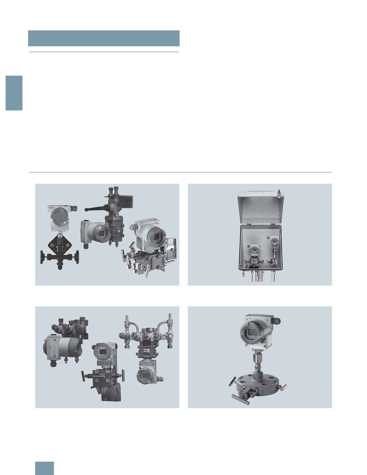
SITRANS P measuring instruments for pressure
Fittings
Technical description
Classification according to pressure equipment directive
■Overview
(DGRL 97/23/EC):
All 21-off fittings can be secured onto walls, racks (72 mm grid)
For gases of fluid group 1 and liquids of fluid group 1; compli-
and vertical and horizontal pipes.
ance with requirements of article 3, paragraph 3 (sound engi-
neering practice).
This offers the advantage when assembling a plant that the shut-
off fittings can be secured first and the lines for the medium and
New standard DIN EN 61518
2
differential pressure connected to them. It is then possible to
check all connections for leaks and to blow out or flush the pipes
The flange connection between transmitter and valve manifold
in order to remove dirt (welding residues, shavings etc.).
was modified in the new standard DIN EN 61518. The only con-
nection thread approved for use in the process flanges of the
The measuring instruments can be screwed onto the shut-off fit-
pressure transmitter is 7/16-20 UNF.
tings right at the end when all piping has been completed.
The valve manifolds for M12 screws, including the accessory
If an instrument has to be removed for maintenance, the fittings
sets, have therefore been deleted.
and pipes remain as they are. It is only necessary to close the
valves - the instrument can then be removed, and refitted follow-
Material acceptance test certificate to EN 10204-3.1
ing maintenance.
If a material acceptance test certificate to EN 10204-3.1 is re-
quired when ordering valve manifolds or shut-off fittings, please
note that a single certificate is sufficient for each ordered item
type. This means that you will only be charged for one certificate
in the cost calculations.
■Pressure transmitters with shut-off fittings - mounting examples
SITRANS P transmitter for gage pressure with double shut-off valve,
SITRANS P pressure transmitter for differential pressure, mounted in pro-
SITRANS P pressure transmitter with multiway cock or 3-spindle valve
tective box (available on request)
manifold
SITRANS P transmitter for differential pressure with 3-way valve manifold,
SITRANS P pressure transmitter mounted on valve combination
3-spindle valve manifold or valve manifold combination DN 5/DN 8
"Monoflange" for direct connection to flanges (available on request)
2/190

SITRANS P measuring instruments for pressure
Fittings
Selection aid
■Selection of available shut-off valves
Transmitters
Shut-off valves for general Page
Shut-off valves for spe- Page
applications
cial applications
Relative and absolute pres-
Shut-off valves/double shut-
2/193
Double shut-off valve DN 5
2/196
sure transmitters with process
off valves to DIN 16270,
for crossover ½-NPT-F to
connection G½" male thread
DIN 16271 and DIN 16272
G½ nipple connection
2
7MF9011-4EA
e.g.
• SITRANS P, Z series
7MF1564-
-.A..
• SITRANS P300
7MF802.-...0.-
2-spindle valve manifold
2/216
• SITRANS P DS III series
DN 5 for installation in pro-
7MF403.-...0.-
and
tective boxes
7MF423.-...0.-
7MF9412-1B
2-way valve manifolds,
2/198
DN 5, forged version
7MF9401-2J. and
7MF9401-2K.
Relative and absolute pres-
Double shut-off valve DN 5
2/196
Double shut-off valve
2/196
sure transmitter with G½"-14
7MF9011-4FA and
DN 5 for process connec-
NPT female thread
7MF9011-4GA
tion
½-NPT
• e.g.
7MF9011-4DA
• SITRANS P Z series
7MF1564-
-.H..
• SITRANS P300
7MF802.-...1.-
• SITRANS P DS III series
7MF403.-...1.-
and
7MF423.-...1.-
Absolute pressure transmitter
2-spindle valve manifold DN 5 2/201
2-spindle valve manifold
2/216
with process connection to
7MF9411-5A.
DN 5 for installation in pro-
IEC 61518
tective boxes
7MF9412-1C.
e.g.
• SITRANS P DS III series
7MF433.-...
2-way valve manifolds,
2/198
DN 5, forged version
7MF9401-2E. and
7MF9401-2F.
2/191
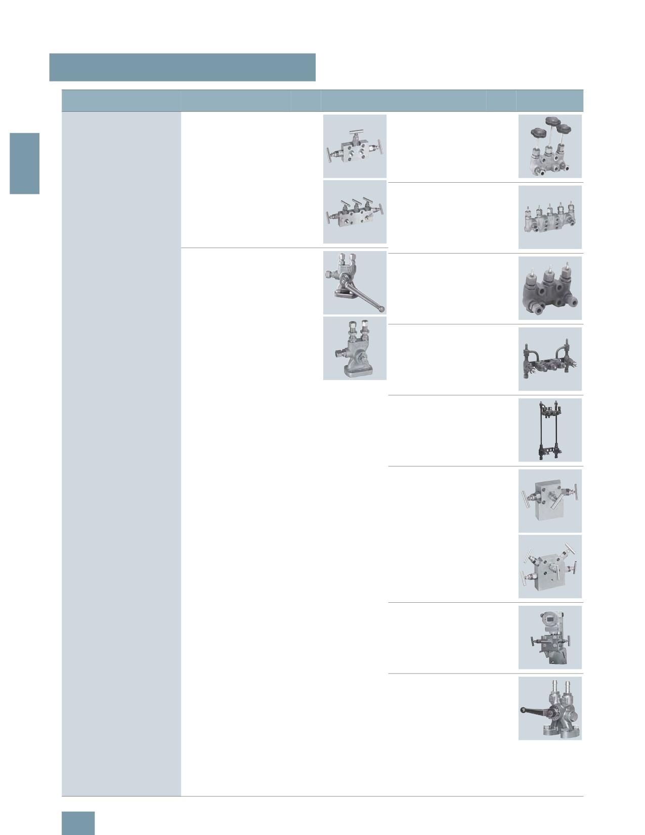
SITRANS P measuring instruments for pressure
Fittings
Selection aid
Transmitters
Shut-off valves for general
Page
Shut-off valves for spe-
Page
applications
cial applications
Differential pressure transmit-
For 3/5-spindle valve manifold
2/201
3-way valve manifolds,
2/206
ter with process connection to
DN 5
DN 5, forged version
IEC 61518
7MF9411-5B. and
7MF9410-1..
7MF9411-5C.
e.g.
2
• SITRANS P DS III series
7MF443.-... and
7MF453.-...
5-way valve manifolds,
2/206
DN 5, forged version
7MF9410-3..
PN 100 multiway cocks
2/204
7MF9004-...
3-way valve manifolds,
2/209
DN 8, forged version
7MF9416-1.. and
7MF9416-2..
Valve manifold combina-
2/212
tion DN 5/DN 8 for vapor
measurement
7MF9416-6..
Valve manifold combina-
2/214
tion DN 8 for vapor mea-
surement
7MF9416-4..
3- and 5-spindle valve
2/216
manifolds for DN 5 for
installation in protective
boxes
7MF9412-1D. and
7MF9412-1E.
3- and 5-spindle valve
2/220
manifolds for vertical dif-
ferential pressure lines
7MF9413-1..
Low-pressure multiway
2/223
cock
7MF9004-4..
2/192

SITRANS P measuring instruments for pressure
Fitttings - Shut-off valves for gage and absolute pressure transmitters
Shut-off valves
to DIN 16270, DIN 16271 and DIN 16272
Selection and Ordering data
Order No.
■Overview
Shut-off valves, form B, DIN 16270
without test collar, pipe union with ferrule
12 S DIN EN ISO 8484-1, without certificate
Material
Maximum permissible
Valve housing
working pressure
2
P250GH
400 bar
7MF9401-8AB
(mat. No. 1.0460)
X 6 CrNiMoTi 17 12 2
400 bar
7MF9401-8AC
(mat. No. 1.4571/316Ti)
Shut-off valves, form B, DIN 16271
with test collar, pipe union with ferrule
12 S DIN EN ISO 8484-1, without certificate
Material
Maximum permissible
Valve housing
working pressure
P250GH
400 bar
7MF9401-8BB
(mat. No. 1.0460)
X 6 CrNiMoTi 17 12 2
400 bar
7MF9401-8BC
(mat. No. 1.4571/316Ti)
Transmitter for pressure with double shut-off valve 7MF9401-...
Double shut-off valves, form B, DIN 16272
The shut-off valves for pressure gages are used to shut off the
with test collar, connection shank,
line of the measured medium when dealing with aggressive and
without certificate
non-aggressive gases, vapors and liquids.
Material
Maximum permissible
Valve housing
working pressure
■Design
CW614N (CuZn39Pb3)250 bar
7MF9401-7DA
A water trap must be connected upstream of the shut-off valve
(mat. No. 2.0402)
in the case of temperatures of the medium above 120 °C. The
P250GH
400 bar
7MF9401-7DB
shut-off valves form B have a shaft with which they can be se-
(mat. No. 1.0460)
cured on an instrument bracket. An adapter is therefore not re-
X 6 CrNiMoTi 17 12 2
400 bar
7MF9401-7DC
quired to secure these valves. The vent/test connection can be
(mat. No. 1.4571/316Ti)
shut off separately with the double shut-off valves DN 5. This per-
mits checking of the zero on the pressure gage. In addition, the
Double shut-off valves, form B, DIN 16272
characteristic of the pressure gage can be checked using an ex-
with test collar, pipe union with ferrule
ternal pressure source.
12 S DIN EN ISO 8484-1, without certificate
Material
Maximum permissible
Valve housing
working pressure
Selection and Ordering data
Order No.
P250GH
400 bar
7MF9401-8DB
Shut-off valves, form B, DIN 16270
(mat. No. 1.0460)
without test collar, connection shank,
X 6 CrNiMoTi 17 12 2
400 bar
7MF9401-8DC
without certificate
(mat. No. 1.4571/316Ti)
Material
Maximum permissible
Accessories
Valve housing
working pressure
Factory test certificate EN 10204-2.2
7MF9000-8AB
CW614N (CuZn39Pb3)250 bar
7MF9401-7AA
(mat. No. 2.0402)
Material acceptance test certificate
7MF9000-8AD
EN 10204-3.1
P250GH
400 bar
7MF9401-7AB
(mat. No. 1.0460)
Instrument bracket, see page 2/197.
X 6 CrNiMoTi 17 12 2
400 bar
7MF9401-7AC
(mat. No. 1.4571/316Ti)
Shut-off valves, form B, DIN 16271
with test collar, connection shank,
without certificate
Material
Maximum permissible
Valve housing
working pressure
CW614N (CuZn39Pb3)250 bar
7MF9401-7BA
(mat. No. 2.0402)
P250GH
400 bar
7MF9401-7BB
(mat. No. 1.0460)
X 6 CrNiMoTi 17 12 2
400 bar
7MF9401-7BC
(mat. No. 1.4571/316Ti)
2/193

SITRANS P measuring instruments for pressure
Fitttings - Shut-off valves for gage and absolute pressure transmitters
Shut-off valves
to DIN 16270, DIN 16271 and DIN 16272
■Characteristic curves
F
0
&
2
%
0
F
D"
%; F
D"
&
; F
D"
F
D"
%
0
D"
1
Permissible operating pressure as a function of the permissible operating
temperature
■Dimensional drawings
!
1#
?
5
&
!
1# ?
'
( "
! &
! #
* = ? 70$ -8
$
9 :
"
1
1
! #
5
3
* = += 7%:
$ -8
" "
1
1
! #
54
11 ! 1#$
$
* = +=
70%0
* "
$
5
%#
5
!,
@ $;
Shut-off valve, form B, dimension drawing, dimensions in mm
@# <
@# 7;
!
1#
?
5
9 :
!
1# ?
&
'
( "
! &
! #
* = ? 70$ -8
$
9 :
"
1
1
! #
5
3
* = += 7%:
$ -8
" "
1
1
! #
54
11 ! 1#$
$
* = +=
70%0
* "
$
5
&
%#
5
!,
@ $;
Double shut-off valve, form B, dimension drawing, dimensions in mm
2/194

SITRANS P measuring instruments for pressure
Fitttings - Shut-off valves for gage and absolute pressure transmitters
Angle adapter
■Overview
■Dimensional drawings
*®
É
2
P300 pressure transmitter with shut-off valve and angle adapter
Angle adapter, dimensions in mm
The angle adapter enables pressure transmitters with top dis-
plays to be read from the front.
Selection and Ordering data
Order No.
Angle adapters
7MF9401-7WA
Material: X 12 CrNiMoTi 17 12 2 (mat. No.
1.45714/316Ti), max. permissible operating
pressure 400 bar
Accessories
Factory test certificate EN 10204-2.2
7MF9000-8AB
Material acceptance test certificate
7MF9000-8AD
EN 10204-3.1
■Characteristic curves
F
0
%
%
0
D"
1
Permissible operating overpressure as a function of the permissible op-
erating temperature
2/195

SITRANS P measuring instruments for pressure
Fitttings - Shut-off valves for gage and absolute pressure transmitters
Double shut-off valves
■Overview
7#;
The double shut-off valves DN 5 are suitable for pressure gages
!
1# :
and pressure transmitters and available in 4 versions:
@#
?
;#;
;7
• Sleeve-collar
• Sleeve-sleeve
2
• Sleeve-nipple
&
• Collar-collar
!
1#
%
% #:;
?#0
?
@# <
■Characteristic curves
@#
7
( "
! &
! #
* = ? 70$ -8
$
9 :
F
"
1
1
! #8
0= >
0
" C
!
#J
7= >
%
Double shut-off valve DN 5 (sleeve-nipple) 7MF9011-4EA, dimensions in
0
F
D"
mm
%; F
D"
8 0= >
%
0
D"
1
&
Permissible operating pressure as a function of the permissible operating
temperature
Selection and Ordering data
Order No.
Double shut-off valves DN 5
8 0= >
Material: X 6 CrNiMoTi 17 13 2 (mat. No.
1.4404/316L), max. permissible working
pressure 420 bar;
( "
! &
! #8
0= >
• Sleeve-sleeve
7MF9011-4DA
"
1
1
! #8
0= >
" C
!
#J
7= >
• Sleeve-nipple connection
7MF9011-4EA
• Sleeve-collar
7MF9011-4FA
• Collar-collar
7MF9011-4GA
Double shut-off valve DN 5 (sleeve-collar) 7MF9011-4FA, dimensions in
mm
Accessories
Factory test certificate EN 10204-2.2
7MF9000-8AB
Material acceptance test certificate
7MF9000-8AD
EN 10204-3.1
~
137
A
■Dimensional drawings
@#
7
% #:;
;#;
:
B
C
&
!
1# ?#0
%
:
?
@# <
( "
! &
! #8
0= >
"
1
1
! #8
0= >
" C
!
#J
7= >
A Connection on device side : ½-14 NPT
Double shut-off valve DN 5 (sleeve-sleeve) 7MF9011-4DA, dimensions in
B Connection on measurement side: ½-14 NPT
mm
C Vent and test connection: ¼-18 NPT
Double shut-off valve DN 5 (collar-collar) 7MF9011-4GA, dimensions in
mm
2/196
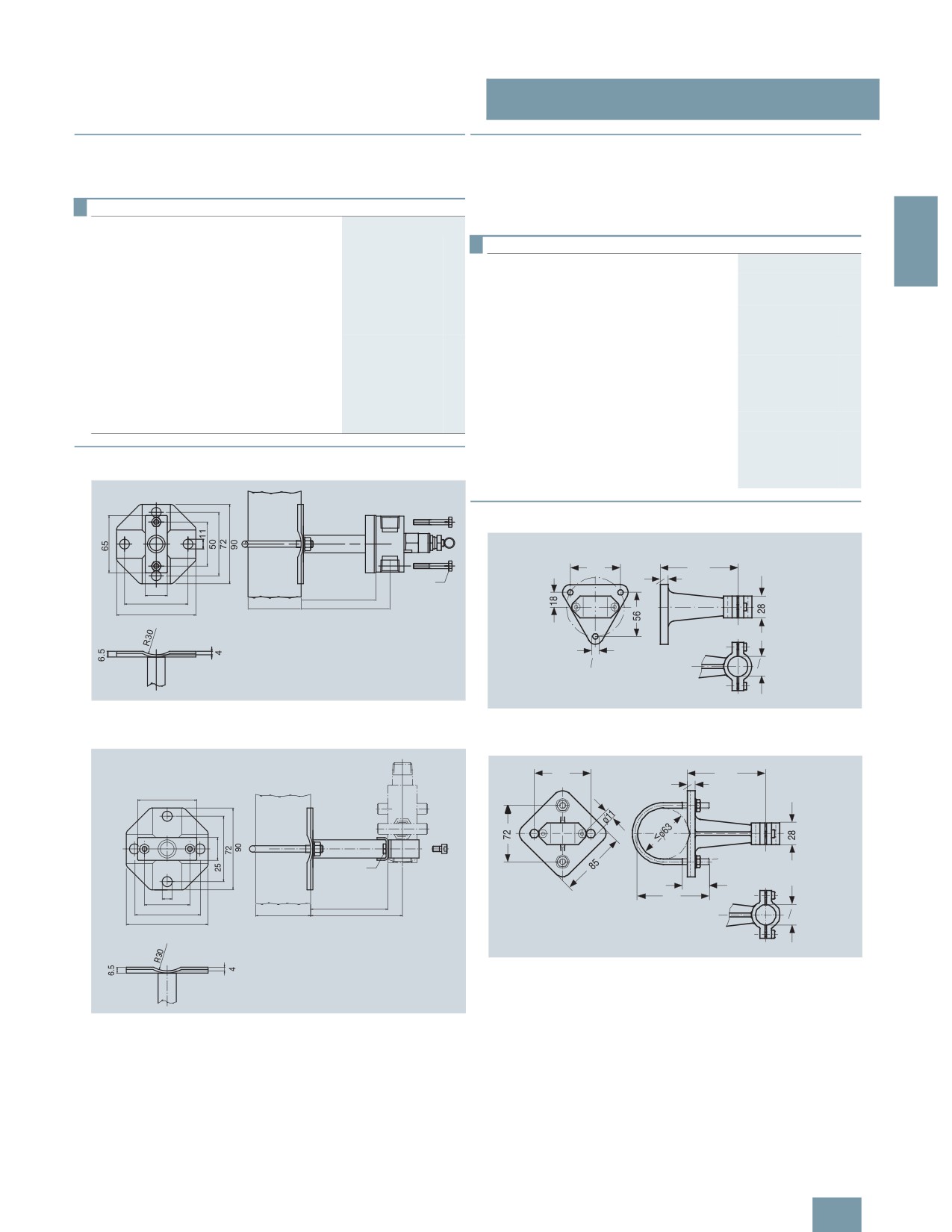
SITRANS P measuring instruments for pressure
Fitttings - Shut-off valves for gage and absolute pressure transmitters
Accessories for
shut-off valves / double shut-off valves
■Overview
■Overview
The mounting set is suitable for the double shut-off valves
The instrument brackets are needed to mount the following units:
7MF9011-4.A and for wall, rack and pipe mounting.
• Pressure gages with threaded connection at the bottom
Selection and Ordering data
Order No.
• Shut-off valves to DIN 16270, DIN 16271 and DIN 16272
Mounting set for shut-off valves
(7MF9401-7.. and 7MF9401-8..)
2
• 7MF9011-4DA und -4EA
7MF9011-8AB
Selection and Ordering data
Order No.
made of stainless steel, scope of delivery:
Instrument bracket, form H, DIN 16281
1x mounting bracket,
made of aluminium alloy, painted black,
2x hexagon screws M6x40,
for wall mounting, screw-type bracket cover
1x mounting clip,
2x washers 8.4 to DIN 125;
• Projection length 60 mm
M56340-A0046
2x hexagon nuts 8.4 to DIN EN 24032
• Projection length 100 mm
M56340-A0047
• 7MF9011-4FA und -4GA
7MF9011-8AC
Instrument bracket, form A, DIN 16281
made of stainless steel, scope of delivery:
made of annealed cast iron, galvanized and
M56340-A0053
1x mounting bracket,
primed for mounting on a wall or rack or or
2x hexagon screws M6x10,
on a sectional rail (horizontal/vertical);
1x mounting clip,
Screw-type bracket cover
2x washers 8.4 to DIN 125;
2x hexagon nuts 8.4 to DIN EN 24032
Instrument bracket, form A, DIN 16281
made of annealed cast iron, galvanized and
M56340-A0079
primed with pipe clamp for mouting on a
■Dimensional drawings
pipe (horizotal/vertical)
Screw-type bracket cover
■Dimensional drawings
$? %
?;
$
? %
6:
:
?
5
Mounting bracket (7MF9011-8AB) for shut-off valves 7MF9011-4DA and
Instrument bracket form H, for wall mounting, M56340-A0046/-A0047,
7MF9011-4EA for wall, rack or pipe mounting, dimensions in mm
dimensions in mm
2
65
;4
SW10
hex. 10
&)
11
5
85
50
1
72
Ø60.3
100
(
90
Instrument bracket form A, wall or pipe mounting,
M56340-A0053/-A0079, dimensions in mm
Mounting bracket (7MF9011-8AC) for shut-off valves 7MF9011-4FA and
7MF9011-4GA for wall, rack or pipe mounting, dimensions in mm
2/197

SITRANS P measuring instruments for pressure
Fitttings - Shut-off valves for gage and absolute pressure transmitters
2-way valve manifolds DN 5
■Overview
■Function
The characteristic of the pressure measuring instrument or pres-
sure transmitter can be tested through the test connection.
A pressure gage for local display can be connected to the test
connection.
2
The two-way valve manifold DN 5 can be used in addition to shut
off and vent the line with the measured medium.
■Accessories
Accessory set for 2-way valve manifold DN 5 for flanging
• A31: 2 screws 7/16-20 UNF x 21/8 inch to ASME B18.3,
1 flat gasket
• A34: 2 screws 7/16-20 UNF x 21/8 inch to ASME B18.3,
1 O-ring (FPM 90)
• A11: 2 screws M10x55 to DIN EN 4762, 2 washers,
1 flat gasket
• A15 (suitable for oxygen): 2 screws M10x55 to DIN EN 4762,
The two-way valve manifold DN 5 (7MF9401-2..) is used to shut
2 washers, 1 flat gasket
off and vent the line with the measured medium, and to test the
• A16: 2 screws M10x55 to DIN EN 4762, 2 washers,
connected pressure gage or transmitter.
1 flat gasket (FPM 90)
Note: M10 screws only permissible up to PN 160!
■ Benefits
Washers Ø 10.5 to DIN 125
• Available for aggressive and non-aggressive liquids and
gases
Flat gaskets made of PTFE, max. 420 bar, 80 °C
• Two connection versions available
O-ring to DIN 3771, 20 x 2.65 - S - FPM90, max. 420 bar, 120 °C
- For flanging to pressure transmitters
- With nipple for connection of pressure gages and pressure
Mounting plate
transmitters for pressure
Made of electrogalvanized sheet-steel
• Max. working pressure 420 bar, with version for oxygen max.
• M11: For wall mounting or for securing on rack (72 mm grid)
100 bar
Scope of delivery:
- 1 mounting plate with bolts for mounting on valve manifold
■Application
• M12: For pipe mounting
The 2-way valve manifold is available in versions for aggressive
Scope of delivery:
and non-aggressive liquids and gases.
- 1 mounting plate M11
- 2 pipe brackets with nuts and washers for pipes with max.
Mounting plates are available for wall mounting, for securing to
Ø 60.3 mm
mounting racks or for pipe mounting.
Valve manifold 100 bar, suitable for oxygen
■Design
• S12: (only in combination with versions for aggressive liquids
and gases): Suitable for oxygen
The 2-way valve manifold DN 5 has 3 connections:
• A process connection (pipe union with ferrule Ø 12 mm)
• A connection for a pressure gage (flange or nipple)
• A test connection (thread G3/8)
The 2-fold valve manifold DN 5 also has an operating valve and
a test valve, each with an internal spindle thread.
Materials used
2-way valve manifold DN 5 for flanging to pressure transmitters
For non-aggressive liquids and
For aggressive
gases
liquids and gases
Component Material
Mat. No.
Material Mat. No.
Housing
P250GH
1.0460
X 6
1.4571/
CrNiMoTi
316Ti
Head parts C 35
1.0501
17 12 2
Spindles
X 12 CrMoS 17
1.4104
Cones
X 35 CrMo 17 hard-
1.4122
ened and tempered
Valve seats X 6 CrNiMoTi 17 12 2
1.4571/316Ti
Packings PTFE
-
PTFE
-
2/198

SITRANS P measuring instruments for pressure
Fitttings - Shut-off valves for gage and absolute pressure transmitters
2-way valve manifolds DN 5
Selection and Ordering data
Order No.
Selection and Ordering data
Order code
Order No.
2-way valve manifold DN 5
7MF9401 -77A
Further designs1)
for flanging to pressure transmitters, max.
Please add "-Z" to Order No. and
working pressure 420 bar, weight 1.85 kg
specify Order code.
(order accessory set and mounting plate with
Order code), without certificate
Accessory set to EN
(required for flanging,
2
• for non-aggressive liquids and gases
2E
weight 0.2 kg)
• for aggressive liquids and gases
2F
2x screws 7/16-20 UNF x
A31
7MF9001-5CC
for fitting to pressure gages or pressure trans-
21/8 inch to ASME B18.3; chromized
mitters for pressure, with nipple connection to
steel
DIN 16284, max. working pressure 420 bar,
1x gasket made of PTFE,
weight 1.8 kg (order mounting plate with
max. permissible 420 bar, 80 °C
Order code)1)
2x screws 7/16-20 UNF x
A34
7MF9401-5AA
• for non-aggressive liquids and gases
2J
21/8 inch to ASME B18.3; chromized
steel
• for aggressive liquids and gases
2K
1x O-ring to DIN 3771, 20 x 2.65
Accessories
- S - FPM90, max. permissble
420 bar, 120 °C
Factory test certificate EN 10204-2.2
7MF9000-8AB
Accessory set to DIN2)
Material acceptance test certificate
7MF9000-8AD
(required for flanging3),
EN 10204-3.1
weight 0.2 kg)
1) For suitable seals, see page 2/228.
2x screws M10x55 to
DIN EN ISO 4762; chromized steel
2x washers Ø 10.5 to DIN 125;
1x gaskets made of PTFE,
max. permissible 420 bar, 80 °C
• Standard design
A11
7MF9001-6AD
• Version for oxygen
A15
7MF9001-6AE
2x screws M10x55 to
A16
7MF9001-6AF
DIN EN ISO 4762; chromized steel
2x washers Ø 10.5 mm
to DIN 125;
1x O-ring to DIN 3771, 20 x 2.65
- S - FPM90, max. permissble
420 bar, 120 °C
Mounting plate
for valve manifold, made of
electrogalvanized sheet-steel
for wall mounting or for securing
M11
7MF9006-6EA
on rack (72 mm grid),
weight 0.5 kg
Scope of delivery:
1 mounting plate with bolts for
mounting on valve manifold
for pipe mounting,
M12
7MF9006-6GA
weight 0.7 kg
Scope of delivery:
1x mounting plate M11, 2x pipe
brackets with nuts and washers
(for pipe with max. Ø 60.3 mm)
Valve manifold 100 bar
Suitable for oxygen, only for
S12
7MF9401-2F. and 7MF9401-2K.
1) When ordering accessory set or mounting together with the 2-way valve
manifold, please use Order code; otherwise use Order No.
2) Flange connections to DIN 19213 only permissible up to PN 160!
3) Only required for versions 7MF9401-2E. und -2F.
2/199