Siemens SITRANS P. Operating Instructions (2019) - page 9

SITRANS P measuring instruments for pressure
Transmitters for food, pharmaceuticals and biotechnology
SITRANS P300 for gage and absolute pressure
Selection and Ordering data
Order No.
Selection and Ordering data
Order No.
SITRANS P300 pressure transmitters for gage
SITRANS P300 pressure transmitters for gage
and absolute pressure with front-flush membrane,
and absolute pressure with front-flush membrane,
single-chamber measuring housing, rating plate
single-chamber measuring housing, rating plate
inscription in English
inscription in English
4 ... 20 mA/HART
F)
7MF8123 -
4 ... 20 mA/HART
F)
7MF8123 -
2
PROFIBUS PA
F)
7MF8124 -
PROFIBUS PA
F)
7MF8124 -
FOUNDATION Fieldbus (FF)
F)
7MF8125 -
FOUNDATION Fieldbus (FF)
F)
7MF8125 -
77777-
7777
77777-7777
Measuring cell filling Measuring cell cleaning
Display
Silicone oil
Standard
1
• Without display, with keys, closed lid4)
1
Inert liquid
Cleanliness level 2 to
3
• With display and keys, closed lid
2
DIN 25410
• With display and keys, lid with macrolon washer
4
FDA compliant fill fluid
(setting on HART devices: mA,
• Neobee oil
Standard
4
on PROFIBUS PA and FOUNDATION Fieldbus
devices: pressure units)
max. span
• With display (setting acc. to specifications, Order
5
0.01 ... 1 bar g
(0.15 ... 14.5 psi g)
B
code "Y21" or "Y22" required), lid with macrolon
0.04 ... 4 bar g
(0.58 ... 58 psi g)
C
washer
0.16 ... 16 bar g
(2.32 ... 232 psi g)
D
• With display and keys, lid with glass pane
6
0.63 ... 63 bar g
(9.14 ... 914 psi g)
E
(setting on HART devices: mA,
on PROFIBUS PA and FOUNDATION Fieldbus
13 ... 1300 mbar a1)
(0.19 ... 18.9 psi a)
S
devices: pressure units)
0.05 ... 5 bar a1)
(0.7 ... 72.5 psi a)
T
• With display (setting acc. to specifications, Order
7
0.03 ... 30 bar a1)
(4.35 ... 435 psi a)
U
code "Y21" or "Y22" required), lid with glass pane
Wetted parts materials
Power supply units see "SITRANS I power supply units and isol. amplifiers".
Seal diaphragm
Measuring cell
Included in delivery of the device:
Stainless steel
Stainless steel
A
• Brief instructions (Leporello)
• CD-ROM with detailed documentation
Process connection
• Flange version with Order code M.., N.., R.. or Q..
7
1) Not with temperature decoupler P00 and P10, not for process connections
(see "Further designs")
R02, R04, R10 and R11, and can only be ordered in conjunction with sili-
cone oil.
Non-wetted parts materials
2) Can only be ordered in conjunction with electrical connection Option A.
• Stainless steel, deep-drawn and electrolytically
4
3) Can only be ordered in conjunction with electrical connection Option B, C,
polished
F or G.
4) Only together with HART electronics.
Version
5) Without cable gland.
• Standard version
1
F) Subject to export regulations AL: 9I999, ECCN: N.
Explosion protection
• Without
A
• With ATEX, Type of protection:
- "Intrinsic safety (EEx ia)"
B
• Zone 20/21/222)
C
• Ex nA/nL (zone 2)3)
E
• With FM „Intrinsic safe“ (cFMUS)
M
Electrical connection / cable entry
• Screwed gland M20x1.5 (Polyamide)4)
A
• Screwed gland M20x1.5 (metal)
B
• Screwed gland M20x1.5 (stainless steel)
C
• M12 connector (without cable socket)
F
• M12 connector (stainless steel, without cable socket)
G
• ½-14 NPT thread, metal5)
H
• ½-14 NPT thread, stainless steel5)
J
2/40

SITRANS P measuring instruments for pressure
Transmitters for food, pharmaceuticals and biotechnology
SITRANS P300 for gage and absolute pressure
Selection and Ordering data
Order code
Selection and Ordering data
Order code
Further designs
HART
PA
FF
Further designs
HART
PA
FF
Add "-Z" to Order No. and specify Order
Add "-Z" to Order No. and specify Order
code.
code.
Mounting bracket
A02
Varivent connection
made completely of stainless steel, for wall or
certified to 3A and EHEDG3)
pipe mounting
• Type N = 68 for Varivent housing
N28
2
DN 40 ... 125 and 1½" ... 6", PN 40
Cable socket for M12 plug
• Metal
A50
Temperature decoupler up to 200 °C7)
P00
• Stainless steel
A51
for version with front-flush diaphragm
Rating plate inscription
Temperature decoupler up to 250 °C
P10
Measuring cell filling: High-temperature oil,
(instead of English)
only in conjunction with measuring cell filling
• German
B10
silicone oil
• French
B12
Bio-Control (Neumo) sanitary connection
• Spanish
B13
certified to 3A and EHEDG3)
• Italian
B14
• DN 50, PN 16
Q53
English rating plate
B21
• DN 65, PN 16
Q54
Pressure units in inH20 or psi
Sanitary process connection to DRD
Quality inspection certificate (Factory cali-
C11
• 65 mm, PN 40
M32
bration) to IEC 60770-21)
SMS socket with union nut
to IEC 60770-2
• 2“
M67
Acceptance test certificate2)
C12
• 2½“
M68
to EN 10204-3.1
• 3“
M69
Factory certificate
C14
SMS threaded socket
to EN 10204-2.2
• 2“
M73
Type of protection IP68
D12
• 2½“
M74
• 3“
M75
Only for SITRANS P300 with front-flush
diaphragm (7MF81..-...)
IDF socket with union nut ISO 2853
Flange to EN 1092-1, form B1
• 2“
M82
• DN 25, PN 403)
M11
• 2½“
M83
• DN 25, PN 1003)
M21
• 3“
M84
• DN 40, PN 40
M13
IDF threaded socket ISO 2853
• DN 40, PN 100
M23
• 2“
M92
• DN 50, PN 16
M04
• 2½“
M93
• DN 50, PN 40
M14
• 3“
M94
• DN 80, PN 25
M06
Sanitary process connection to
• DN 80, PN 40
M16
NEUMO Bio-Connect screw connection
Flanges to ASME B16.5
certified to 3A and EHEDG3)
• 1", class 1503)
M40
• DN 50, PN 16
Q05
• 1½", class 150
M41
• DN 65, PN 16
Q06
• 2", class 150
M42
• DN 80, PN 16
Q07
• 3", class 150
M43
• DN 100, PN 16
Q08
• 4", class 150
M44
• DN 2“, PN 16
Q13
• 1", class 3003)
M45
• DN 2½“, PN 16
Q14
• 1½", class 300
M46
• DN 3“, PN 16
Q15
• 2", class 300
M47
• DN 4“, PN 16
Q16
• 3", class 300
M48
Sanitary process connection to
NEUMO Bio-Connect flange connection
Threaded connection acc. to DIN 3852-2,
certified to 3A and EHEDG3)
Form A
• DN 50, PN 16
Q23
• G ¾“-A, flush-mounted4)
R01
• DN 65, PN 16
Q24
• G 1“-A, flush-mounted4)
R02
• DN 80, PN 16
Q25
• G 2“-A, flush-mounted4)
R04
• DN 100, PN 16
Q26
Tank connection5)
• DN 2“, PN 16
Q31
Sealing is included in delivery
• DN 2½“, PN 16
Q32
• TG 52/50, PN 40
R10
• DN 3“, PN 16
Q33
• TG 52/150, PN 40
R11
• DN 4“, PN 16
Q34
Sanitary process connection according
Sanitary process connection to
DIN 11851 (Dairy connection)
NEUMO Bio-Connect clamp connection
certified to 3A6)
3)
certified to 3A and EHEDG
• DN 50, PN 25
N04
• DN 50, PN 16
Q39
• DN 80, PN 25
N06
• DN 65, PN 10
Q40
Tri-Clamp connection according
• DN 80, PN 10
Q41
DIN 32676/ISO 2852
• DN 100, PN 10
Q42
certified to 3A6)
• DN 2½“, PN 16
Q48
• DN 50/2“, PN 16
N14
• DN 3“, PN 10
Q49
• DN 65/3“, PN 10
N15
• DN 4“, PN 10
Q50
2/41

SITRANS P measuring instruments for pressure
Transmitters for food, pharmaceuticals and biotechnology
SITRANS P300 for gage and absolute pressure
Selection and Ordering data
Order code
Selection and Ordering data
Order code
Further designs
HART
PA
FF
Additional data
HART
PA
FF
Add "-Z" to Order No. and specify Order
Add "-Z" to Order No. and specify Order
code.
code.
Sanitary process connection to
Measuring range to be set
Y01
NEUMO Connect S flange connection
Specify in plain text V (max. 5 digits):
2
certified to 3A and EHEDG
Y01: ... up to ... mbar, bar, kPa, MPa, psi
• DN 50, PN 16
Q63
Measuring point number (TAG No.)
Y15
• DN 65, PN 10
Q64
Max. 16 characters, specify in plain text:
• DN 80, PN 10
Q65
Y15:
• DN 100, PN 10
Q66
Measuring point text
Y16
• DN 2“, PN 16
Q72
Max. 27 characters, specify in plain text:
• DN 2½“, PN 10
Q73
Y16:
• DN 3“, PN 10
Q74
• DN 4“, PN 10
Q75
Entry of HART TAG
Y17
Max. 8 characters, specify in plain text:
Aseptic threaded socket to DIN 11864-1
Y17:
Form A
Setting of pressure indication in pressure
Y21
• DN 50, PN 25
N33
units
• DN 65, PN 25
N34
Specify in plain text (standard setting: mA):
• DN 80, PN 25
N35
Y21: mbar, bar, kPa, MPa, psi, ...
• DN 100, PN 25
N36
Note:
Aseptic flange with notch to DIN 11864-2
The following pressure units can be selected:
Form A
bar, mbar, mm H2O*), inH2O*), ftH2O*),
• DN 50, PN 16
N43
mmHG, inHG, psi, Pa, kPa, MPa, g/cm2,
• DN 65, PN 16
N44
kg/cm2, Torr, ATM or %
*) ref. temperature 20 °C
• DN 80, PN 16
N45
• DN 100, PN 16
N46
Setting of pressure indicator in
Y22 +
non-pressure units
Y01
Aseptic flange with groove to DIN 11864-2
Specify in plain text:
Form A
Y22:
up to
l, m3, m, USg, ...
• DN 50, PN 16
N43 +
(specification of measuring range in pressure
P11
units "Y01" is essential, unit with max. 5 char-
• DN 65, PN 16
N44 +
acters)
P11
Preset bus address
Y25
• DN 80, PN 16
N45 +
possible between 1 ... 126)
P11
Specify in plain text:
• DN 100, PN 16
N46 +
Y25:
P11
Only "Y01" and "Y21" can be factory preset
Aseptic clamp with groove to DIN 11864-3
Form A
= available
• DN 50, PN 25
N53
Ordering example
• DN 65, PN 25
N54
Item line:
7MF8023-1DB24-1AB7-Z
• DN 80, PN 16
N55
B line:
A02 + Y01 + Y21
• DN 100, PN 16
N56
C line:
Y01: 1 ... 10 bar (14.5 ... 145 psi)
1) When the manufacture’s certificate M (calibration certificate) has to be
C line:
Y21: bar (psi)
ordered for transmitters with diaphragm seals, it is recommended only to
order this certificate exclusively with the diaphragm seals. The measuring
accuracy of the total combination is certified here.
2) Whe the acceptance test certificate 3.1 for transmitters with direct-con-
nected diaphragm seals is ordered, this certificate must also be ordered
with the corresponding seals.
3) Special Viton seal included in delivery.
4) Lower measuring limit -100 mbar g (1.45 psi g).
5) The weldable socket can be ordered under accessories
6) Certified to 3A.
The maximum temperatures of the medium depend on the respective cell
fillings.
7)
3A certification only if used in conjunction with 3A-compliant sealing rings.
2/42
SITRANS P measuring instruments for pressure
Transmitters for food, pharmaceuticals and biotechnology
SITRANS P300 for gage and absolute pressure
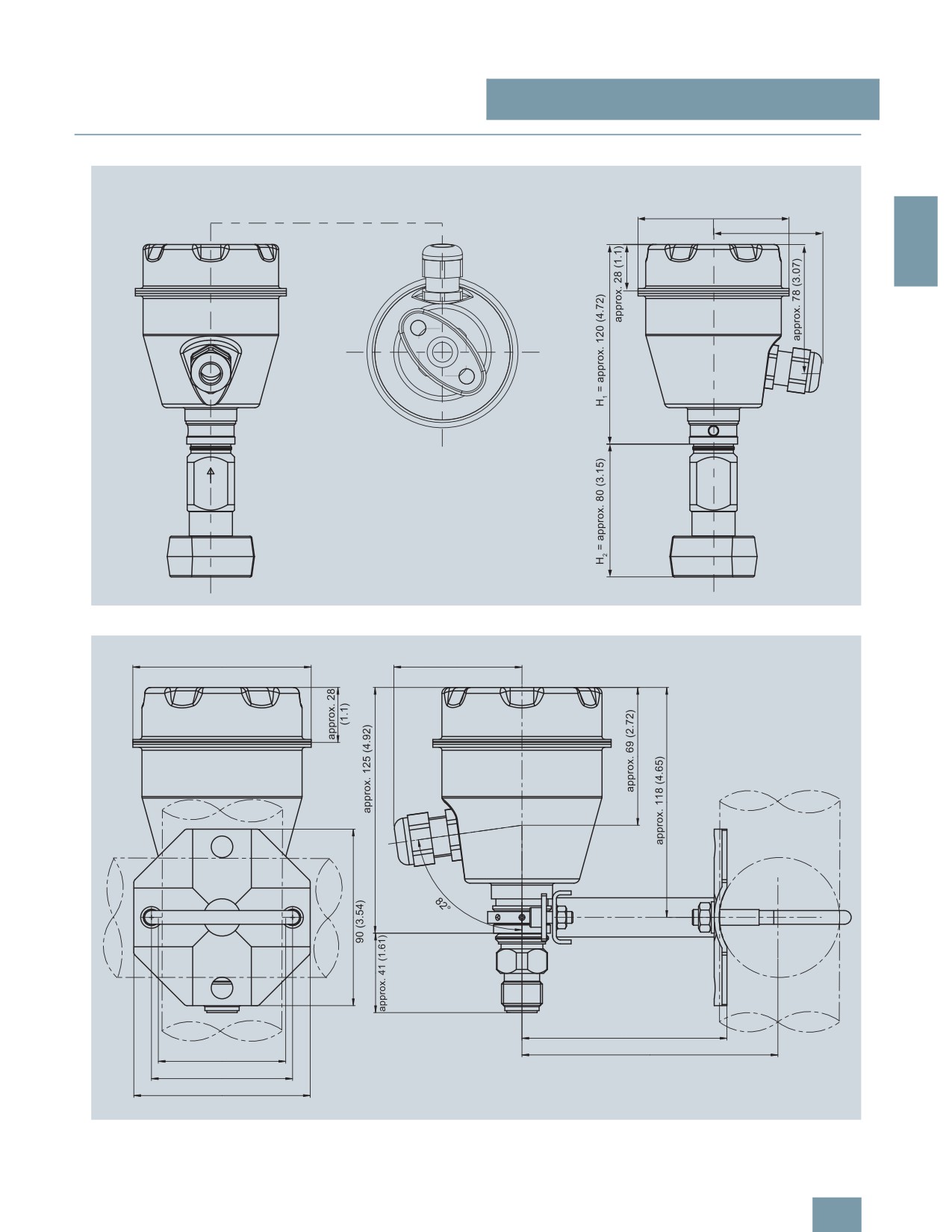
■Dimensional drawings
ෘ
DSSUR[
2
SITRANS P300, with oval flange, dimensions in mm (inch)
ෘ
DSSUR[
DSSUR[
DSSUR[
SITRANS P300, process connection M20 x 1,5, with mounted mounting bracket, dimensions in mm (inch)
2/43

SITRANS P measuring instruments for pressure
Transmitters for food, pharmaceuticals and biotechnology
SITRANS P300 for gage and absolute pressure
ෘ
2
7HPSHUDWXUH GHFRXSOHU
SITRANS P300, front-flush, dimensions in mm (inch)
The diagram shows a SITRANS P300 with an example of a
flange. In this drawing the height is subdivided into H1 and H2.
H1 = Height of the SITRANS P300 up to a defined cross-section
H2 = Height of the flange up to this defined cross-section
Only the height H2 is indicated in the dimensions of the flanges.
2/44

SITRANS P measuring instruments for pressure
Transmitters for food, pharmaceuticals and biotechnology
SITRANS P300 for gage and absolute pressure
Flanges to EN and ASME
Sanitary process connection to DRD
Flanges to EN
DN
PN
∅D
H2
EN 1092-1
50
40
105 mm (4.1“)
Approx.
DN
PN
∅D
H2
52 mm (2“)
25
40
115 mm (4.5“)
Approx.
'
2
25
100
140 mm (5.5“)
52 mm (2“)
40
40
150 mm (5.9“)
'
40
100
170 mm (6.7“)
50
16
165 mm (6.5“)
Sanitary process screw connection to NEUMO Bio-Connect
50
40
165 mm (6.5“)
DN
PN
∅D
H2
80
16
200 mm (7.9“)
50
16
82 mm (3.2“)
Approx.
80
40
200 mm (7.9“)
52 mm (2“)
65
16
105 mm (4.1“)
80
16
115 mm (4.5“)
Flanges to ASME
100
16
145 mm (5.7“)
ASME B16.5
'
2“
16
82 mm (3.2“)
DN
class
∅D
H2
2½“
16
105 mm (4.1“)
1“
150
110 mm (4.3“)
Approx.
3“
16
105 mm (4.1“)
1“
300
125 mm (4.9“)
52 mm (2“)
4“
16
145 mm (5.7“)
1½“
150
130 mm (5.1“)
'
1½“
300
155 mm (6.1“)
2“
150
150 mm (5.9“)
Sanitary connection to NEUMO Bio-Connect
2“
300
165 mm (6.5“)
flange connection
3“
150
190 mm (7.5“)
3“
300
210 mm (8.1“)
DN
PN
∅D
H2
4“
150
230 mm (9.1“)
50
16
110 mm (4.3“)
Approx.
4“
300
255 mm (10.0“)
52 mm (2“)
65
16
140 mm (5.5“)
NuG and pharmaceutical connections
'
80
16
150 mm (5.9“)
Connections to DIN
100
16
175 mm (6.9“)
DIN 11851 (Dairy connection)
2“
16
100 mm (3.9“)
DN PN
∅D
H2
2½“
16
110 mm (4.3“)
50
25
92 mm (3.6“)
Approx.
3“
16
140 mm (5.5“)
52 mm (2“)
80
25
127 mm (5.0“)
4“
16
175 mm (6.9“)
'
Sanitary connection to NEUMO Bio-Connect
clamp connection
Tri-Clamp according DIN 32676
DN
PN
∅D
2
H
DN PN
∅D
H2
50
16
77,4 mm (3.0“)
Approx.
50
16
64 mm (2.5“)
Approx.
52 mm (2“)
65
10
90,9 mm (3.6“)
52 mm (2“)
65
16
91 mm (3.6“)
80
10
106 mm (4.2“)
100
10
119 mm (4.7“)
'
'
2“
16
64 mm (2.5“)
Other connections
2½“
16
77,4 mm (3.0“)
Varivent connection
3“
10
90,9 mm (3.6“)
DN
PN
∅D
H2
4“
10
119 mm (4.7“)
40 ... 125
40
84 mm
Approx.
(3.3“)
52 mm (2“)
Sanitary connection to NEUMO Bio-Connect S
flange connection
'
DN
PN
∅D
2
H
50
16
125 mm (4.9“)
Approx.
52 mm (2“)
Bio-Control connection
65
10
145 mm (5.7“)
'
DN PN
∅D
H2
80
10
155 mm (6.1“)
50
16
90 mm (3.5“)
Approx.
100
10
180 mm (7.1“)
52 mm (2“)
65
16
120 mm (4.7“)
2“
16
125 mm (4.9“)
2½“
10
135 mm (5.3“)
'
3“
10
145 mm (5.7“)
4“
10
180 mm (7.1“)
2/45

SITRANS P measuring instruments for pressure
Transmitters for food, pharmaceuticals and biotechnology
SITRANS P300 for gage and absolute pressure
Thread connection G¾“, G1“ and G2“ to DIN 3852
Aseptic threaded socket to DIN 11864-1 Form A
DN PN
∅D
H2
DN
PN
∅D
H2
¾“
63
37 mm (1.5“)
Approx. 45
50
25
78 x 1/6“
Approx. 52
mm (1.8“)
mm (2.1“)
65
25
95 x 1/6“
1“
63
48 mm (1.9“)
Approx. 47
80
25
110 x ¼“
2
mm (1.9“)
'
100
25
130 x ¼“
2“
63
78 mm (3.1“)
Approx. 52
mm (2“)
'
Tank connection TG52/50 und TG52/150
Aseptic flange with notch to DIN 11864-2 Form A
DN
PN
∅D
H2
DN
PN
∅D
H2
25
40
63 mm (2.5“)
Approx. 63
mm (2.5“)
50
16
94
Approx. 52
mm (2.1“)
25
40
63 mm (2.5“)
Approx.170
65
16
113
mm (6.7“)
80
16
133
'
'
100
16
159
SMS socket with union nut
Aseptic flange with groove to DIN 11864-2 Form A
DN
PN
∅D
H2
DN
PN
∅D
H2
2“
25
84 mm (3.3“)
Approx. 52
mm (2.1“)
50
16
94
Approx. 52
2½“
25
100 mm (3.9“)
mm (2.1“)
65
16
113
3“
25
114 mm (4.5“)
80
16
133
'
'
100
16
159
Aseptic clamp with groove to DIN 11864-3 Form A
SMS threaded socket
DN
PN
∅D
H2
DN
PN
∅D
H2
50
25
77,5
Approx. 52
2“
25
70 x 1/6 mm
Approx. 52
mm (2.1“)
mm (2.1“)
65
25
91
2½“
25
85 x 1/6 mm
80
16
106
3“
25
98 x 1/6 mm
100
16
130
'
'
IDF socket with union nut
DN
PN
∅D
H2
2“
25
77 mm (3“)
Approx. 52
mm (2.1“)
2½“
25
91 mm (3.6“)
3“
25
106 mm (4.2“)
'
IDF threaded socket
DN
PN
∅D
H2
2“
25
64 mm (2.5“)
Approx. 52
mm (2.1“)
2½“
25
77,5 mm (3.1“)
3“
25
91 mm (3.6“)
'
2/46

SITRANS P measuring instruments for pressure
Transmitters for gage pressure for the paper industry
SITRANS P300 and DS III series
with PMC connection - Technical description
• Small long-term drift
■Overview
• Wetted parts made of Hastelloy
• Infinitely adjustable spans from 30 mbar g to 16 bar g for DS III
with HART interface
• Nominal measuring range from 1 mbar g to 16 bar g for DS III
with PROFIBUS PA and FOUNDATION Fieldbus interface
2
• Infinitely adjustable spans from 30 mbar g to 16 bar g for
SITRANS P300 with HART interface
• Nominal measuring range from 1 bar g to 16 bar g for
SITRANS P300 with PROFIBUS PA interface
• High measuring accuracy
• Parameterization over control keys and HART communication,
or over PROFIBUS PA or FOUNDATION Fieldbus interface (DS
III only).
■Application
The pressure transmitters of the DS III series, can be used in in-
dustrial areas with extreme chemical and mechanical loads.
Electromagnetic compatibility in the range 10 kHz ... 1 GHz
makes the DS III pressure transmitters suitable for locations with
high electromagnetic emissions.
Pressure transmitters with type of protection "Intrinsic safety" and
"Explosion-proof" may be installed within potentially explosive at-
mospheres (zone 1) or in zone 0. The pressure transmitters are
provided with an EC type examination certificate and comply
with the corresponding harmonized European standards
(ATEX).
Pressure transmitters with the type of protection "Intrinsic safety"
for use in zone 0 may be operated with power supply units of cat-
egory "ia" and "ib".
The transmitters can be equipped with various designs of re-
mote seals for special applications such as the measurement of
highly viscous substances.
The SITRANS P300 and DS III pressure transmitters have been
fitted with special process connections for the paper industry.
The pressure transmitter can be operated locally over 3 control
With the two process connection threads 1½" and 1" flush at the
keys or programmed externally over HART communication or
front, the SITRANS P300 and DS III transmitters can be used for
over PROFIBUS PA or FOUNDATION Fieldbus interface (only
all processes in the paper industry.
DS III).
SITRANS P300 and DS III series pressure transmitters are digital
SITRANS P, DS III series
pressure transmitters featuring extensive user-friendliness and
Measured variable: Gage pressure of aggressive and non-
high accuracy. The parameterization is performed using control
aggressive gases, vapors and liquids.
keys, over HART communication, PROFIBUS PA or
FOUNDATION Fieldbus interface (DS III only).
Span (infinitely adjustable)
Extensive functionality enables the pressure transmitter to be
For DS III HART: 0.03 ... 16 bar g (0.433 ... 232 psi g)
precisely adapted to the plant’s requirements. Operation is very
Nominal measuring range
simple in spite of the numerous setting options.
For DS III PA and FF: 1 ... 16 bar g (14.5 ... 232 psi g)
Transmitters with type of protection "Intrinsic safety" and "Explo-
sion-proof" may be installed within potentially explosive atmo-
SITRANS P300
spheres (zone 1) or in zone 0. The transmitters are provided with
an EC type examination certificate and comply with the corre-
Span (infinitely adjustable)
sponding harmonized European standards (ATEX).
For DS III HART: 0.03 ... 16 bar g (0.433 ... 232 psi g)
Various versions of the pressure transmitters are available for
Nominal measuring range
measuring:
For DS III PA: 1 ... 16 bar g (14.5 ... 232 psi g)
• Gage pressure
• Filling level
• Volume level
• Mass level
■ Benefits
• High quality and long life
• High reliability even under extreme chemical and mechanical
loads, e.g. abrasion.
• For aggressive and non-aggressive gases, vapors and liquids
• Extensive diagnosis and simulation functions
• Minimum conformity error
2/47

SITRANS P measuring instruments for pressure
Transmitters for gage pressure for the paper industry
SITRANS P300 and DS III series
with PMC connection - Technical description
SITRANS P300
■Design
The device comprises:
SITRANS P, DS III series
• Electronics
• Housing
• Measuring cell
2
Device front view, SITRANS P DS III
The transmitter comprises a range of different components, de-
pending on the order specifications. The various options are
Perspective view of the SITRANS P300
listed in the ordering information. The components described
below are the same for all transmitters.
The housing has a screwable cover (3), with or without an in-
spection window depending on the version. The electrical termi-
The rating plate (3, Figure "Front view") with the Order No. is lo-
nal housing, the buttons for operation of the device and, de-
cated on the side of the housing. The specified number together
pending on the version, the digital display are located under this
with the ordering information provide details on the optional de-
cover. The connections for the auxiliary power UH and the shield
sign details and on the possible measuring range (physical
are in the terminal housing. The cable gland is on the side of the
properties of built-in sensor element).
housing. The measuring cell with the process connection (5) is
The approval label is located on the opposite side.
located on the underside of the housing. Depending on the ver-
sion of the device, the measuring cell with the process connec-
The housing is made of die-cast aluminium or stainless steel pre-
tion may differ from the one shown in the diagram.
cision casting. A round cover is screwed on at the front and rear
of the housing. The front cover (6) can be fitted with a viewing
pane so that the measured values can be read directly on the
digital display. The inlet (4) for the electrical connection is lo-
cated either on the left or right side. The unused opening on the
opposite side is sealed by a blanking plug. The protective earth
connection is located on the rear of the housing.
The electrical connections for the power supply and screen are
accessible by unscrewing the rear cover. The bottom part of the
housing contains the measuring cell with process connection
(1). The measuring cell is prevented from rotating by a locking
screw (8). As the result of this modular design, the measuring
cell and the electronics can be replaced separately from each
other. The set parameter data are retained.
At the top of the housing is a plastic cover (5), which hides the
input keys.
2/48
SITRANS P measuring instruments for pressure
Transmitters for gage pressure for the paper industry
SITRANS P300 and DS III series
with PMC connection - Technical description
Operation of the electronics with PROFIBUS PA communica-
■Function
tion
Operation of the electronics with PROFIBUS PA communica-
tion
,
2
,
(
"
4
"
!
($ 2
++
,
"
2( >
4
+
++
,
,
+
,
,
,
7
>5
3
1
1 4
$
%
%
(
!
&
<
!
,
0
,
1
1 4
;
+
* ) (
3
%
(
!
&
?
&
11
1
0
,
5
5
1
;
&
!
& F
?
&
11
5
5
1
!
:
B
(
4
:
2( >
4
7
>5
3
$
%
<
!
* !
!
4
@
11
(
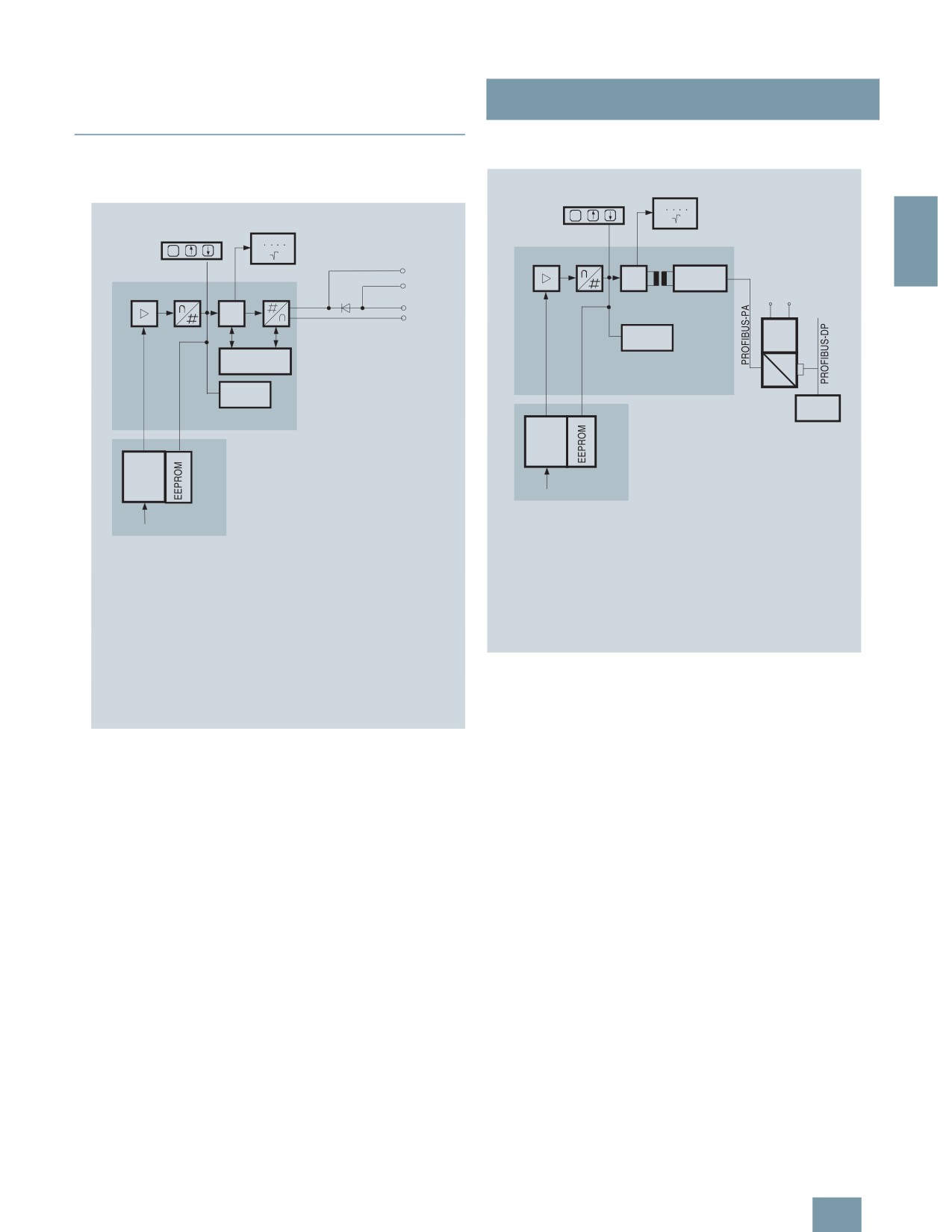
Function diagram of electronics
2
& F
The bridge output voltage created by the sensor (1, Figure
"Function diagram of electronics") is amplified by the instrument
amplifier (2) and digitized in the analog-to-digital converter (3).
The digital information is evaluated in the microcontroller, its lin-
Function diagram of electronics
earity and temperature response corrected, and provided on the
PROFIBUS PA through an electrically isolated PA interface (7).
The bridge output voltage created by the sensor (1, Figure
"Function diagram of electronics") is amplified by the instrument
The data specific to the measuring cell, the electronics data, and
amplifier (2) and digitized in the analog-to-digital converter (3).
the parameter data are stored in the two non-volatile memories
The digital information is evaluated in a microcontroller, its linear-
(6). The first memory is linked with the measuring cell, the sec-
ity and temperature response corrected, and converted in a dig-
ond with the electronics. This modular design means that the
ital-to-analog converter (5) into an output current of 4 to 20 mA.
electronics and the measuring cell can be replaced separately
from one another.
The diode circuit (10) protects against incorrect polarity.
Using the three input keys (8) you can parameterize the pressure
The data specific to the measuring cell, the electronics data, and
transmitter directly at the point of measurement. The input keys
the parameter data are stored in the two non-volatile memories
can also be used to control the view of the results, the error mes-
(6). The one memory is coupled to the measuring cell, the other
sages and the operating modes on the digital display (9).
to the electronics. As the result of this modular design, the elec-
tronics and the measuring cell can be replaced separately from
The results with status values and diagnostic values are trans-
each other.
ferred by cyclic data transmission on the PROFIBUS PA. Param-
eterization data and error messages are transferred by acyclic
Using the 3 input keys (8) you can parameterize the pressure
data transmission. Special software such as SIMATIC PDM is re-
transmitter directly at the point of measurement. The input keys
quired for this.
can also be used to control the view of the results, the error mes-
sages and the operating modes on the digital display (9).
The HART modem (7) permits parameterization using a protocol
according to the HART specification.
The pressure transmitters with spans ≤ 63 bar g measure the in-
put pressure compared to atmosphere, transmitters with spans
≥ 160 bar g compared to vacuum.
2/49

SITRANS P measuring instruments for pressure
Transmitters for gage pressure for the paper industry
SITRANS P300 and DS III series
with PMC connection - Technical description
Mode of operation of the FOUNDATION Fieldbus electronics
Mode of operation of the measuring cell
Measuring cell for gage pressure with front-flush diaphragm
,
2
BB
"
4
!
,
++
,
%
!
5
1
"
0
B
H
!
;
& F
+
Measuring cell for gage pressure, with front-flush diaphragm, function
,
diagram
The pressure pe is applied through the process connection
,
7
>5
3
(2, Figure "Measuring cell for gage pressure, with front-flush di-
1
1 4
$
%
aphragm for paper industry, function diagram") to the measuring
%
(
!
&
<
*
!
cell (1). This pressure is subsequently transmitted further
0
,
;
+
through the seal diaphragm (3) and the filling liquid (4) to the sil-
?
&
11
& F
icon pressure sensor (5) whose measuring diaphragm is then
5
5
1
flexed. This changes the resistance of the four piezo-resistors fit-
!
:
BB
4
ted in the diaphragm in a bridge circuit. This change in resis-
tance results in a bridge output voltage proportional to the input
pressure.
Function diagram of electronics
Parameterization
The bridge output voltage created by the sensor (1, Figure
Depending on the version, there are a range of options for pa-
"Function diagram of electronics") is amplified by the instrument
rameterizing the pressure transmitter and for setting or scanning
amplifier (2) and digitized in the analog-to-digital converter (3).
the parameters.
The digital information is evaluated in the microcontroller, its lin-
earity and temperature response corrected, and provided on the
Parameterization using the input keys (local operation)
FOUNDATION Fieldbus through an electrically isolated
With the input keys you can easily set the most important param-
FOUNDATION Fieldbus Interface (7).
eters without any additional equipment.
The data specific to the measuring cell, the electronics data, and
Parameterization using HART communication
the parameter data are stored in the two non-volatile memories
(6). The one memory is coupled to the measuring cell, the other
Parameterization using HART communication is performed with
to the electronics. As the result of this modular design, the elec-
a HART communicator or a PC.
tronics and the measuring cell can be replaced separately from
each other.
Using the three input keys (8) you can parameterize the pressure
transmitter directly at the point of measurement. The input keys
can also be used to control the view of the results, the error mes-
> (=
%
###
sages and the operating modes on the digital display (9).
1
The results with status values and diagnostic values are trans-
2( >
ferred by cyclic data transmission on the FOUNDATION
11
Fieldbus. Parameterization data and error messages are trans-
ferred by acyclic data transmission. Special software such as
National Instruments Configurator is required for this.
Communication between a HART communicator and a pressure
transmitter
When parameterizing with the HART communicator, the connec-
tion is made directly to the 2-wire system.
2/50

SITRANS P measuring instruments for pressure
Transmitters for gage pressure for the paper industry
SITRANS P300 and DS III series
with PMC connection - Technical description
Parameterization through PROFIBUS PA interface
Fully digital communication through PROFIBUS PA, profile 3.0, is
particularly user-friendly. The PROFIBUS puts the DS III PA is in
> (=
%
### ;
connection with a process control system, e.g. SIMATIC PSC 7.
1
Communication is possible even in a potentially explosive envi-
ronment.
"
2( >
2
For parameterization through PROFIBUS you need suitable soft-
1 ! 1
ware, e.g. SIMATIC PDM (Process Device Manager).
%
Parameterization through FOUNDATION Fieldbus Interface
Fully digital communication through FOUNDATION Fieldbus is
particularly user-friendly. Through the FOUNDATION Fieldbus
HART communication between a PC communicator and a pressure
the DS III FF is connected to a process control system. Commu-
transmitter
nication is possible even in a potentially explosive environment.
When parameterizing with a PC, the connection is made through
For parameterization through the FOUNDATION Fieldbus you
a HART modem.
need suitable software, e.g. National Instruments Configurator.
The signals needed for communication in conformity with the
Adjustable parameters for DS III PA and FF and P300 PA and FF
HART 5.x or 6.x protocols are superimposed on the output cur-
rent using the Frequency Shift Keying (FSK) method.
Adjustable parameters
Input keys
PROFIBUS PA and
FOUNDATION
Adjustable parameter DS III HART and P300 HART
Fieldbus interface
Parameters
Input keys
HART com-
Electrical damping
x
x
munication
Zero adjustment (correction of x
x
Start of scale
x
x
position)
Full-scale value
x
x
Key and/or function disabling x
x
Electrical damping
x
x
Source of measured-value dis- x
x
Start-of-scale value without application
x
x
play
of a pressure ("Blind setting")
Physical dimension of display x
x
Full-scale value without application of a
x
x
Position of decimal point
x
x
pressure ("Blind setting")
Bus address
x
x
Zero adjustment
x
x
Adjustment of characteristic
x
x
Current transmitter
x
x
Input of characteristic
x
Fault current
x
x
Freely-programmable LCD
x
Disabling of keys, write protection
x
x1)
Diagnostic functions
x
Type of dimension and actual dimension x
x
Characteristic (linear)
x
x
Input of characteristic
x
Diagnostic functions for DS III PA and FF and P300 PA and FF
Freely-programmable LCD
x
• Event counter
• Slave pointer
Diagnostics functions
x
• Maintenance timer
1)
Cancel apart from write protection
• Simulation functions
Diagnostic functions for DS III HART and P300 HART
• Display of zero correction
• Zero correction display
• Limit transmitter
• Event counter
• Saturation alarm
• Limit transmitter
• Saturation alarm
Physical dimensions available for the display
• Slave pointer
Physical variable
Physical dimensions
• Simulation functions
Pressure (setting can also be
MPa, kPa, Pa, bar, mbar, torr, atm,
• Maintenance timer
made in the factory)
psi, g/cm2, kg/cm2, mmH2O,
mmH2O (4 °C), inH2O, inH20
Available physical units of display for DS III HART and P300
(4 °C), ftH
2O (20 °C), mmHg, inHg
HART
Level (height data)
m, cm, mm, ft, in, yd
Physical variable
Physical dimensions
Mass
g, kg, t, lb, Ston, Lton, oz
Pressure (setting can also be
Pa, MPa, kPa, bar, mbar, torr, atm,
Volume
m3, dm3, hl, yd3, ft3, in3, US gallon,
made in the factory)
psi, g/cm2, kg/cm2, inH2O, inH2O
lmp, gallon, bushel, barrel, barrel
(4 °C), mmH2O, ftH2O (20 °C),
liquid
inHg, mmHg
Temperature
K, °C, °F, °R
Level (height data)
m, cm, mm, ft, in
Miscellaneous
%
Volume
m3, dm3, hl, yd3, ft3, in3, US gallon,
lmp, gallon, bushel, barrel, barrel
liquid
Mass
g, kg, t, lb, Ston, Lton, oz
Temperature
K, °C, °F, °R
Miscellaneous
%, mA
2/51

SITRANS P measuring instruments for pressure
Transmitters for gage pressure for the paper industry
DS III series with PMC connection
■ Technical specifications
SITRANS P, DS III series for gage pressure with PMC connection for the paper industry
HART
PROFIBUS PA or FOUNDATION Fieldbus
Input
2
Measured variable
Gage pressure
Spans (infinitely adjustable) or
Span
Max. perm. test pres-
Nominal measuring
Max. perm. test pres-
nominal measuring range and
sure
range
sure
max. permissible test pressure
0.01 ... 1 bar g
6 bar g
1 bar g
6 bar g
(0.145 ... 14.5 psi g)
(87 psi g)
(14.5 psi g)
(87 psi g)
0.04 ... 4 bar g
10 bar g
4 bar g
10 bar g
(0.58 ... 58 psi g)
(145 psi g)
(58 psi g)
(145 psi g)
0.16 ... 16 bar g
32 bar g
16 bar g
32 bar g
(2.32 ... 232 psi g)
(464 psi g)
(232 psi g)
(464 psi g)
Lower measuring limit
• Measuring cell with silicone oil filling
100 mbar a (1.45 psi a)
Upper measuring limit
100% of max. span
Output
Output signal
4 ... 20 mA
Digital PROFIBUS PA or FOUNDATION Fieldbus
signal
• Lower limit (infinitely adjustable)
3.55 mA, factory preset to 3.84 mA
-
• Upper limit (infinitely adjustable)
23 mA, factory preset to 20.5 mA or optionally set
-
to 22.0 mA
Load
• Without HART communication
RB ≤ (UH - 10.5 V)/0.023 A in Ω,
-
UH : Power supply in V
• With HART communication
RB = 230 ... 500 Ω (SIMATIC PDM) or
-
RB = 230 ... 1100 Ω (HART Communicator)
Physical bus
-
IEC 61158-2
With polarity reversal protection
-
Yes
Accuracy
To EN 60770-1
Reference conditions
Increasing characteristic, start-of-scale value 0 bar, stainless steel seal diaphragm, silicone oil filling,
(All error data refer always refer to the set
room temperature 25 °C (77 °F) r: Span ratio (r = max. span/set span)
span)
Error in measurement and fixed-point setting
(including hysteresis and repeatability)
• Linear characteristic
≤ 0,075%
- r ≤ 10
≤ (0.0029 ⋅ r + 0.071)%
-
10 < r ≤ 30
≤ (0.0045 ⋅ r + 0.071)%
-
30 < r ≤ 100
≤ (0.005 ⋅ r + 0.05)%
Long-term drift (temperature change ± 30 °C
≤ (0.25 ⋅ r)% every 5 years
≤ 0.25% every 5 years
(± 54 °F))
Influence of ambient temperature
• at -10 ... +60 °C (14 ... 140 °F)
≤ (0.08 ⋅ r + 0.1)%
≤ 0,3%
• at -40 ... -10 °C and +60 ... +85 °C
≤ (0.1 ⋅ r + 0.15)%/10 K
≤ 0.25%/10 K
(-40 ... +14 °F and 140 ... 185 °F)
Influence of medium temperature
• Temperature difference between medium
3 mbar/10 K (0.04 psi/10 K)
temperature and ambient temperature
Influence of mounting position
≤ 0.1 mbar g (0.00145 psi g) per 10° inclination
Measured Value Resolution
-
3 ⋅ 10-5 of nominal measuring range
2/52
SITRANS P measuring instruments for pressure
Transmitters for gage pressure for the paper industry
DS III series with PMC connection
SITRANS P, DS III series for gage pressure with PMC connection for the paper industry
HART
PROFIBUS PA or FOUNDATION Fieldbus
Rated operating conditions
Degree of protection (to EN 60529)
IP65, IP68, NEMA X, enclosure cleaning, resistant to lyes, steam to 150° C (302 °F)
Process temperature
-20 ... +100 °C (-4 ... +212 °F)
2
Ambient conditions
• Ambient temperature
-20 ... +85 °C (-4 ... +185 °F)
• Storage temperature
-50 ... +85 °C (-58 ... +185 °F)
• Climatic class
- Condensation
Permissible
• Electromagnetic compatibility
- Emitted interference and interference im-
To EN 61326 and NAMUR NE 21
munity
Design
Weight (without options)
≈ 1.5 kg (≈ 3.3 lb)
Housing material
Poor in copper die-cast aluminium, GD-AlSi12 or stainless steel precision casting, mat. No. 1.4408
Wetted parts materials
Stainless steel
• Gasket (standard)
PTFE flat gasket
• O-ring (minibolt)
FPM (Viton) or optionally: FFPM or NBR
Measuring cell filling
Silicone oil or inert filling liquid
Process connection (standard)
Front-flush, 1½", PMC Standard design
Process connection (minibolt)
Front-flush, 1", minibolt design
Power supply UH
Supplied through bus
Terminal voltage on transmitter
10.5 ... 45 V DC
-
10.5 ... 30 V DC in intrinsically-safe mode
Separate 24 V power supply necessary
-
No
Bus voltage
• Not Ex
-
9 ... 32 V
• With intrinsically-safe operation
-
9 ... 24 V
Current consumption
• Basic current (max.)
-
12.5 mA
• Startup current ≤ basic current
-
Yes
• Max. current in event of fault
-
15.5 mA
Fault disconnection electronics (FDE) avail-
-
Yes
able
Certificate and approvals
Classification according to pressure equip-
For gases of fluid group 1 and liquids of fluid group 1; complies with requirements of Article 3, para-
ment directive (DRGL 97/23/EC)
graph 3 (sound engineering practice)
2/53

SITRANS P measuring instruments for pressure
Transmitters for gage pressure for the paper industry
DS III series with PMC connection
SITRANS P, DS III series for gage pressure with PMC connection
Communication FOUNDATION Fieldbus
for the paper industry
Function blocks
3 function blocks analog input, 1
HART communication
function block PID
HART communication
230 ... 1100 Ω
• Analog input
Protocol
HART Version 5.x
- Adaptation to customer-specif-
Yes, linearly rising or falling char-
ic process variables
acteristic
2
Software for computer
SIMATIC PDM
- Electrical damping T63 , adjust-
0 ... 100 s
PROFIBUS PA communication
able
Simultaneous communication with
4
- Simulation function
Output/input (can be locked within
master class 2 (max.)
the device with a bridge)
The address can be set using
Configuration tool or local opera-
- Failure mode
Can be parameterized (last good
tion (standard setting address
value, substitute value, incorrect
126)
value)
Cyclic data usage
- Limit monitoring
Yes, one upper and lower warning
limit and one alarm limit respec-
• Output byte
5 (one measuring value) or
tively
10 (two measuring values)
- Square-rooted characteristic
Yes
• Input byte
0, 1, or 2 (register operating mode
for flow measurement
and reset function for metering)
• PID
Standard FF function block
Internal preprocessing
• Physical block
1 Resource block
Device profile
PROFIBUS PA Profile for Process
Control Devices Version 3.0,
Transducer blocks
1 transducer block Pressure with
Class B
calibration, 1 transducer block
LCD
Function blocks
2
• Pressure transducer block
• Analog input
-
Can be calibrated by applying
Yes
- Adaptation to customer-specif-
Yes, linearly rising or falling char-
two pressures
ic process variables
acteristic
-
Monitoring of sensor limits
Yes
- Electrical damping T63 , adjust-
0 ... 100 s
able
-
Simulation function: Measured
Constant value or over parameter-
pressure value, sensor temper-
izable ramp function
- Simulation function
Input /Output
ature and electronics tempera-
- Failure mode
Can be parameterized (last good
ture
value, substitute value, incorrect
value)
- Limit monitoring
Yes, one upper and lower warning
limit and one alarm limit respec-
tively
• Register (totalizer)
Can be reset, preset, optional
direction of counting, simulation
function of register output
- Failure mode
Can be parameterized (summation
with last good value, continuous
summation, summation with incor-
rect value)
- Limit monitoring
One upper and lower warning limit
and one alarm limit respectively
• Physical block
1
Transducer blocks
2
• Pressure transducer block
- Can be calibrated by applying
Yes
two pressures
- Monitoring of sensor limits
Yes
- Specification of a container
Max. 30 nodes
characteristic with
- Square-rooted characteristic
Yes
for flow measurement
- Gradual volume suppression
Parameterizable
and implementation point of
square-root extraction
- Simulation function for mea-
Constant value or over parameter-
sured pressure value and sen-
izable ramp function
sor temperature
2/54

SITRANS P measuring instruments for pressure
Transmitters for gage pressure for the paper industry
DS III series with PMC connection
Selection and Ordering data
Order No.
Selection and Ordering data
Order No.
SITRANS P pressure transmitters for gage
7MF4133 -
SITRANS P pressure transmitter for gage
pressure, with PMC connection
pressure, with PMC connection
77777-7777
series DS III HART
DS III PA (PROFIBUS PA) series
7MF4134 -
Measuring cell filling Measuring cell
DS III FF series (FOUNDATION Fieldbus)
7MF4135 -
cleaning
2
Silicone oil
Standard
1
77777-7777
Inert liquid
Grease-free
3
Measuring cell filling Measuring cell
Span
cleaning
0.01 ... 1 bar g1)
(0.15 ... 14.5 psi g)1)
B
Silicone oil
Standard
1
0.04 ... 4 bar g
(0.58 ... 58 psi g)
C
Inert liquid
Grease-free
3
0.16 ... 16 bar g
(2.32 ... 232 psi g)
D
Nominal measuring range
Wetted parts materials
1 bar g1)
(14.5 psi g)1)
B
Seal diaphragm
Connection shank
4 bar g
(58 psi g)
C
16 bar g
(232 psi g)
D
Hastelloy
Stainless steel
B
Wetted parts materials
Process connection
Seal diaphragm
Connection shank
• PMC Style Standard: Thread 1½"
2
• PMC Style Mini bolt: 1" front-flush (min. span:
3
Hastelloy
Stainless steel
B
500 mbar (7.25 psi), can not be ordered with mit
Process connection
1-bar (14.5 psi) measuring cell (Option B))
• PMC Style Standard: front-flush 1½"
2
Non-wetted parts materials
• PMC Style Mini bolt: front-flush 1"
3
• Housing made of die-cast aluminum
0
(min. span: 500 mbar (7.25 psi), can not be or-
• Housing stainless steel precision casting
3
dered with mit 1-bar (14.5 psi) measuring cell
(Option B))
Version
Non-wetted parts materials
• Standard version
1
• Housing made of die-cast aluminum
0
• International version, English label inscriptions,
2
documentation in 5 languages on CD
• Housing stainless steel precision casting
3
Explosion protection
Version
• None
A
• Standard version
1
• International version, English label inscriptions,
2
Electrical connection / cable entry
documentation in 5 languages on CD
• Female thread M20x1.5
B
Explosion protection
• Female thread ½-14 NPT
C
• None
A
• M12 connectors (metal)
F
Electrical connection / cable inlet
Display
• Screwed gland M20x1.5
B
• Without indicator
0
• Screwed gland ½-14 NPT
C
• Without visible digital indicator (digital indicator }
1
hidden, setting: mA)
• M12 connectors (metal)
F
• With visible digital indication, setting: mA
6
Display
• With customer-specific digital indication (setting
7
• Without indicator
0
as specified, Order code "Y21" or "Y22"
• Without visible digital indicator (digital indicator }
1
required)
hidden, setting: mA)
Power supply units see "SITRANS I power supply units and isolation
• With visible digital display
6
amplifiers".
• With customer-specific digital display (setting as
7
specified, Order code "Y21" or required)
Included in delivery of the device:
• Brief instructions (Leporello)
Included in delivery of the device:
• CD-ROM with detailed documentation
• Brief instructions (Leporello)
• Sealing ring
• CD-ROM with detailed documentation
• Sealing ring
1) Only with "PMC Style Standard" process connection
1) Only with "PMC Style Standard" process connection
2/55

SITRANS P measuring instruments for pressure
Transmitters for gage pressure for the paper industry
DS III series with PMC connection
Selection and Ordering data
Order code
Selection and Ordering data
Order code
Further designs
HART
PA
FF
Additional data
HART
PA
FF
Add "-Z" to Order No. and specify Order
Add "-Z" to Order No. and specify Order
code.
code.
M12 cable sockets (metal)
A50
Measuring range to be set
Y01
2
Specify in plain text (max. 5 digits):
Rating plate inscription
Y01: ... up to ... mbar, bar, kPa, MPa, psi
(instead of German)
Measuring point number (TAG No.)
Y15
• English
B11
Max. 16 characters, specify in plain text:
• French
B12
Y15:
• Spanish
B13
Measuring point text
Y16
• Italian
B14
Max. 27 characters, specify in plain text:
English rating plate
B21
Y16:
Pressure units in inH20 or psi
Entry of HART address (TAG)
Y17
Quality inspection certificate (Factory cali-
C11
Max. 8 characters, specify in plain text:
bration) to IEC 60770-2
Y17:
Acceptance test certificate
C12
Setting of pressure indication in pressure
Y21
units
To EN 10204-3.1
Specify in plain text (standard setting: mA):
Factory certificate
C14
Y21: mbar, bar, kPa, MPa, psi, ...
To EN 10204-2.2
Note:
The following pressure units can be selected:
Output signal can be set to upper limit of
D05
bar, mbar, mm H2O*), inH2O*), ftH2O*),
22.0 mA
mmHG, inHG, psi, Pa, kPa, MPa, g/cm2,
kg/cm2, Torr, ATM or %
Mounting
*) ref. temperature 20 °C
• Weldable sockets for standard 1½" threaded
P01
connection
Setting of pressure indication in
Y22 +
non-pressure units
Y01
• Weldable socket for mini bolt connection 1"
P02
(incl. screw 5/16-18 UNC-2B and washer)
Specify in plain text:
Y22:
up to
l, m3, m, USg, ...
(specification of measuring range in pressure
units "Y01" is essential, unit with
max. 5 characters)
Preset bus address
Y25
Max. 8 characters, specify in plain text:
Y25:
Only "Y01" and "Y21" can be factory preset
= available
Ordering example
Item line:
7MF4133-1DB20-1AB7-Z
B line:
A22 + Y01 + Y21
C line:
Y01: 1 ... 10 bar (14.5 ... 145 psi)
C line:
Y21: bar (psi)
2/56

SITRANS P measuring instruments for pressure
Transmitters for gage pressure for the paper industry
DS III series with PMC connection
■Dimensional drawings
;
00
$;?:%
$%#<0%
$
#?%
@# %
$
#
7%
;
?
2
:0
$
#<%
$
#
%
%
0 %
:
; %
<
$%#?%%
#
,"
!
!
3
%
+
#
!
!,
@ $;
!
!8 0= >
0
>
1
!
;
+
! $!
!
$
&
54
&
5
!
%
?
&
& &
3
:
&
4
F
3
$
4
@
4
$
5
5
!
%
%
(
@#
11
$
#:<
5%
5
!
5
!!
%
<
11
$%#?
5% 4
1 11!
1
5
!
SITRANS P DS III pressure transmitters for gage pressure, with PMC connection, dimensions in mm (inch)
The diagram shows a SITRANS P DS III with an example of a
PMC Style standard
flange. In this drawing the height is subdivided into H1 and H2.
DN
PN
∅D
H2
H1 = Height of the SITRANS P DS III up to a defined cross-sec-
40.9 mm (1.6")
Approx.
tion
36.8 mm
H2 = Height of the flange up to this defined cross-section
(1.4’’)
Only the height H2 is indicated in the dimensions of the flanges.
0
[
'
PMC Style minibolt
DN
PN
∅D
H2
26.3 mm (1.0")
Approx.
33.1 mm
(1.3’’)
'
2 ULQJ VXUIDFH
ERUH KROH PP
ಯ ZLWKRXW EXUU
PMC Style standard (left) and PMC Style minibolt (right) weldable sock-
ets, dimensions in mm (inch)
Material: Stainless steel, mat. No. 1.4404 / 316L
2/57

SITRANS P measuring instruments for pressure
Transmitters for gage pressure for the paper industry
SITRANS P300 with PMC connection
■ Technical specifications
SITRANS P300 for gage pressure with PMC connection for the paper industry
HART
PROFIBUS PA
Input
2
Measured variable
Gage pressure (flush-mounted)
Spans (infinitely adjustable) or
Span
Max. perm. test pres-
Nominal measuring
Max. perm. test pres-
nominal measuring range and
sure
range
sure
max. permissible test pressure
0.01 ... 1 bar g
6 bar g
1 bar g
6 bar g
(0.15 ... 14.5 psi g)
(87 psi g)
(14.5 psi g)
(87 psi g)
0.04 ... 4 bar g
10 bar g
4 bar g
10 bar g
(0.58 ... 58 psi g)
(145 psi g)
(58 psi g)
(145 psi g)
0.16 ... 16 bar g
32 bar g
16 bar g
32 bar g
(2.3 ... 232 psi g)
(464 psi g)
(232 psi g)
(464 psi g)
Depending on the process connection, the span
Depending on the process connection, the nomi-
may differ from these values
nal measuring range may differ from these values
Lower measuring limit
• Measuring cell with silicone oil
100 mbar a (1.45 psi a)
Upper measuring limit
• Measuring cell with silicone oil
100% of max. span
100% of the max. nominal measuring range
Output
Output signal
4 ... 20 mA
Digital PROFIBUS PA signal
Physical bus
-
IEC 61158-2
With polarity reversal protection
No
Yes
Electrical damping T63 (step width 0.1 s)
Set to 0.1 s (0 ... 100 s)
Accuracy
To EN 60770-1
Reference conditions
Increasing characteristic, start-of-scale value 0 bar, stainless steel seal diaphragm, measuring cell
(All error data refer always refer to the set
with silicone oil, room temperature 25 °C (77 °F), span ratio (r = max. span/set span)
span)
Measurement deviation with cut-off point set-
ting, including hysteresis and repeatability.
Linear characteristic curve
≤ 0,075%
• r ≤ 10
≤ (0.0029 ⋅ r + 0.071)%
• 10 < r ≤ 30
≤ (0.0045 ⋅ r + 0.071)%
• 30 < r ≤ 100
≤ (0.005 ⋅ r + 0.05)%
Settling time T63 without electrical damping
Approx. 0.2 s
Long-term drift at ±30 °C (±54 °F)
≤ (0.25 ⋅ r)%/5 years
≤ 0.25%/5 years
Influence of ambient temperature
• at -10 ... +60 °C (14 ... 140 °F)
≤ (0.1 ⋅ r + 0.2)%
≤ 0,3%
• at -40 ... -10 °C and +60 ... +85 °C
≤ (0.1 ⋅ r + 0.15)%/10 K
≤ 0.25%/10 K
(-40 ... 14 °F and 140 ... 185 °F)
Influence of the medium temperature (only
with front-flush diaphragm)
• Temperature difference between medium
3 mbar/10 K (0.04 psi/10 K)
temperature and ambient temperature
Rated operating conditions
Installation conditions
Ambient temperature
Observe the temperature class in areas subject to explosion hazard.
• Measuring cell with silicone oil
-40 ... +85 °C (-40 ... +185 °F)
• Digital display
-30 ... +85 °C (-22 ... +185 °F)
• Storage temperature
-50 ... +85 °C (-58 ... +185 °F)
Climatic class
Condensation
Permissible
Degree of protection to EN 60529
IP65, IP68, NEMA X, enclosure cleaning, resistant to lyes, steam to 150° C (302 °F)
Electromagnetic compatibility
• Emitted interference and interfer. immunity
To EN 61326 and NAMUR NE 21
2/58

SITRANS P measuring instruments for pressure
Transmitters for gage pressure for the paper industry
SITRANS P300 with PMC connection
SITRANS P300 for gage pressure with PMC connection for the paper industry
HART
PROFIBUS PA
Medium conditions
Process temperature
• Measuring cell with silicone oil
-40 ... +100 °C (-40 ... +212 °F)
2
Design
Weight (without options)
Approx. 1 kg (2.2 lb)
Housing material
Stainless steel, mat. No. 1.4301/304
Material of parts in contact with the medium
• Seal diaphragm
Hastelloy C276, mat. No. 2.4819
• Measuring cell filling
Silicone oil
Power supply UH
Terminal voltage on transmitter
10.5 ... 42 V DC
Supplied through bus
for intrinsically safe operation: 10.5 ... 30 V DC
Separate power supply
-
Not necessary
Bus voltage
• Without EEx
-
9 ... 32 V
• For intrinsically-safe operation
-
9 ... 24 V
Current consumption
• Max. basic current
-
12.5 mA
• Startup current ≤ basic current
-
Yes
• Max. fault current in the event of a fault
-
15.5 mA
Fault disconnection electronics (FDE)
-
Available
Certificate and approvals
Classification according to pressure equip-
For gases of fluid group 1 and liquids of fluid group 1; complies with requirements of Article 3, para-
ment directive (DRGL 97/23/EC)
graph 3 (sound engineering practice)
Explosion protection
Intrinsic safety "i"
PTB 05 ATEX 2048
Identification
Ex II 1/2 G EEx ia/ib IIB/IIC T4, T5, T6
Permissible ambient temperature
• Temperature class T4
-40 ... +85 °C (-40 ... +185 °F)
• Temperature class T5
-40 ... +70 °C (-40 ... +158 °F)
• Temperature class T6
-40 ... +60 °C (-40 ... +140 °F)
Connection
To certified intrinsically-safe circuits with maxi-
To certified intrinsically-safe circuits with maxi-
mum values:
mum values:
Ui = 30 V, Ii = 100 mA,
FISCO supply unit:
Pi = 750 mW, Ri = 300 Ω
Ui = 17.5 V, Ii = 380 mA, Pi = 5.32 W
Linear barrier:
Ui = 24 V, Ii = 250 mA, Pi = 1.2 W
Effective inner capacitance:
Ci = 6 nF
Ci = 1.1 nF
Effective inner inductance:
Li = 0.4 mH
Li ≤ 7 μH
Explosion protection to FM for USA and
Canada (cFMUS)
• Identification (DIP) or (IS); (NI)
Certificate of Compliance 3025099
CL I, DIV 1, GP ABCD T4 ... T6; CL II, DIV 1, GP EFG; CL III; CL I, ZN 0/1 AEx ia IIC T4 ... T6;
CL I, DIV 2, GP ABCD T4 ... T6; CL II, DIV 2, GP FG; CL III
• Identification (DIP) or (IS)
Certificate of Compliance 3025099C
CL I, DIV 1, GP ABCD T4 ... T6; CL II, DIV 1, GP EFG; CL III; Ex ia IIC 4 ... T6;
CL I, DIV 2, GP ABCD T4 ... T6; CL II, DIV 2, GP FG; CL III
2/59

SITRANS P measuring instruments for pressure
Transmitters for gage pressure for the paper industry
SITRANS P300 with PMC connection
SITRANS P300 for gage pressure with PMC connection for the
Communication FOUNDATION Fieldbus
paper industry
Function blocks
3 function blocks analog input,
HART communication
1 function block PID
HART communication
230 ... 1100 Ω
• Analog input
Protocol
HART Version 5.x
- Adaptation to customer-specif-
Yes, linearly rising or falling char-
2
ic process variables
acteristic
Software for computer
SIMATIC PDM
- Electrical damping T63 , adjust-
0 ... 100 s
able
PROFIBUS PA communication
- Simulation function
Output/input (can be locked within
Simultaneous communication with
4
the device with a bridge)
master class 2 (max.)
- Failure mode
Can be parameterized (last good
The address can be set using
configuration tool
value, substitute value, incorrect
Local operation
value)
(standard setting Address 126)
- Limit monitoring
Yes, one upper and lower warning
Cyclic data usage
limit and one alarm limit respec-
tively
• Output byte
One measuring value: 5 bytes
- Square-rooted characteristic
Yes
Two measuring values: 10 bytes
for flow measurement
• Input byte
Register operating mode: 1 bytes
• PID
Standard FF function block
Reset function due to metering.
• Physical block
1 Resource block
1 bytes
Transducer blocks
1 transducer block Pressure with
Device profile
PROFIBUS PA Profile for Process
calibration, 1 transducer block
Control Devices Version 3.0,
LCD
Class B
• Pressure transducer block
Function blocks
2
- Can be calibrated by applying
Yes
• Analog input
two pressures
- Adaptation to customer-specific
Linearly rising or falling character-
- Monitoring of sensor limits
Yes
process variables
istic
- Simulation function: Measured
Constant value or over parameter-
- Electrical damping T63
0 ... 100 s adjustable
pressure value, sensor temper-
izable ramp function
- Simulation function
Input /Output
ature and electronics tempera-
ture
- Limit monitoring
One upper and lower warning limit
and one alarm limit respectively
• Register (totalizer)
Can be reset and preset
Optional direction of counting
Simulation function of the register
output
- Limit monitoring
One upper and lower warning limit
and one alarm limit respectively
• Physical block
1
Transducer blocks
2
• Pressure transducer block
- Monitoring of sensor limits
Yes
- Specification of a container
Max. 31 nodes
characteristic with
- Characteristic
Linear
- Simulation function
Available
• Transducer block "Electronic tem-
perature"
- Simulation function
Available
2/60

SITRANS P measuring instruments for pressure
Transmitters for gage pressure for the paper industry
SITRANS P300 with PMC connection
Selection and Ordering data
Order No.
Selection and Ordering data
Order code
SITRANS P300 pressure transmitters with PMC
Further designs
HART
PA
FF
connection, single-chamber measuring housing,
Add "-Z" to Order No. and specify Order
rating plate inscription in English
code.
4 ... 20 mA/HART
F)
7MF8123 -
Cable socket for M12 plug
PROFIBUS PA
F)
7MF8124 -
• Metal
A50
2
• Stainless steel
A51
FOUNDATION Fieldbus (FF)
F)
7MF8125 -
Rating plate inscription
77777-
7777
(instead of English)
Measuring cell filling Measuring cell cleaning
• German
B10
Silicone oil
Standard
1
• French
B12
Inert liquid
Cleanliness level 2 to
3
• Spanish
B13
DIN 25410
• Italian
B14
Span
English rating plate
B21
1 bar g
(14.5 psi g)
B
Pressure units in inH2O or psi
4 bar g
(58 psi g)
C
16 bar g
(232 psi g)
D
Quality inspection certificate (Factory cali- C11
bration) to IEC 60770-2
Wetted parts materials
Seal diaphragm
Measuring cell
Acceptance test certificate
C12
To EN 10204-3.1
Hastelloy
Stainless steel
B
Process connection
Factory certificate
C14
• PMC Style Standard: Thread 1½"
2
To EN 10204-2.2
• PMC Style Mini bolt: 1" front-flush (min. span: 500
3
Set output signal to upper limit of 22.0 mA D05
mbar (7.25 psi), can not be ordered with mit 1-bar
(14.5 psi) measuring cell (Option B))
Type of protection IP68
D12
Mounting
Non-wetted parts materials
• Weldable sockets for standard 1½" threaded P01
• Stainless steel, deep-drawn and electrolytically
4
connection
polished
• Weldable socket for mini bolt connection 1"
P02
Version
(incl. screw 5/16-18 UNC-2B and washer)
• Standard version
1
Additional data
Explosion protection
Add "-Z" to Order No. and
• None
A
specify Order code.
• With ATEX, Type of protection:
Measuring range to be set
Y01
- "Intrinsic safety (EEx ia)"
B
Specify in plain text (max. 5 digits):
• Zone 20/21/221)
C
Y01: ... up to ... mbar, bar, kPa, MPa, psi
• Ex nA/nL (zone 2)2)
E
Measuring point number (TAG No.)
Y15
• With FM + CSA, Type of protection:
Max. 16 characters, specify in plain text: Y15:
- "Intrinsic Safe (is)" (planned)
M
Electrical connection / cable entry
Measuring point text
Y16
• Screwed gland M20x1.5 (Polyamide)3)
A
Max. 27 characters, specify in plain text: Y16:
• Screwed gland M20x1.5 (metal)
B
• Screwed gland M20x1.5 (stainless steel)
C
Entry of HART address (TAG)
Y17
• M12 connector (without cable socket)
F
Max. 8 characters, specify in plain text:
• M12 connector (stainless steel, without cable socket)
G
Y17:
• ½-14 NPT thread, metal4)
H
Setting of pressure indication in pressure
Y21
• ½-14 NPT thread, stainless steel4)
J
units
Display
Specify in plain text (standard setting: mA):
Y21: mbar, bar, kPa, MPa, psi, ...
• Without display, with keys, closed lid3)
1
Note: The following pressure units can be
2
• With display and keys, closed lid
selected:
• With display and keys, lid with glass pane
6
bar, mbar, mm H2O*), inH2O*), ftH2O*),
(setting on HART devices: mA, on PROFIBUS PA
mmHG, inHG, psi, Pa, kPa, MPa, g/cm2,
and FOUNDATION Fieldbus devices: pressure unit)
kg/cm2, Torr, ATM or %
*) ref. temperature 20 °C
7
• With display (setting acc. to specifications, Order
code "Y21" or "Y22" required), lid with glass pane
Setting of pressure indication in non-pres- Y22 +
sure units
Y01
Power supply units see "SITRANS I power supply units and isolation
Specify in plain text:
amplifiers".
Y22:
up to
l, m3, m, USg, ...
Included in delivery of the device:
(specification of measuring range in pressure
• Brief instructions (Leporello)
units "Y01" is essential, unit with max. 5 char-
• CD-ROM with detailed documentation
acters)
• Sealing ring
Preset bus address
Y25
Specify in plain text:
1) Can only be ordered in conjunction with electrical connection Option A.
Y25:
2) Can only be ordered in conjunction with electrical connection Option B, C,
F or G.
Only "Y01" and "Y21" can be factory preset
3) Only together with HART electronics.
= available
4) Without cable gland.
F) Subject to export regulations AL: 9I999, ECCN: N.
2/61
SITRANS P measuring instruments for pressure
Transmitters for gage pressure for the paper industry
SITRANS P300 with PMC connection
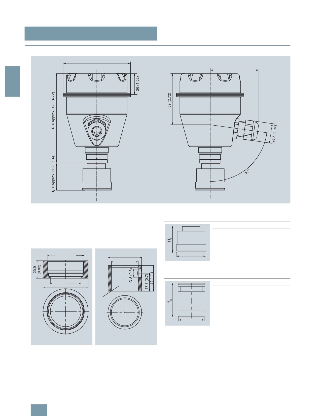
■Dimensional drawings
ෘ
2
SITRANS P300 pressure transmitters for gage pressure, with PMC connection, dimensions in mm (inch)
The diagram shows a SITRANS P300 with an example of a
PMC Style Standard
flange. In this drawing the height is subdivided into H1 and H2.
DN PN
∅D
H2
H1 = Height of the SITRANS P300 up to a defined cross-section
40.4 mm (1.6") Approx.
H2 = Height of the flange up to this defined cross-section
36.8 mm
(1.4’’)
Only the height H2 is indicated in the dimensions of the flanges.
0
[
'
PMC Style Minibolt
DN PN
∅D
H2
26.3 mm (1.0") Approx.
33.1 mm
(1.3’’)
'
2 ULQJ VXUIDFH
ERUH KROH PP
ಯ ZLWKRXW EXUU
PMC Style Standard (left) and PMC Style Minibolt (right) weldable sock-
ets, dimensions in mm (inch)
Material: Stainless steel, mat. No. 1.4404 / 316L
2/62

SITRANS P measuring instruments for pressure
Transmitters for gage, absolute and differential pressure, flow and level
DS III, DS III PA and DS III FF series
Technical description
■Overview
2
SITRANS P pressure transmitters, DS III series, are digital pres-
• Infinitely adjustable span from 0.01 mbar to 400 mbar for
sure transmitters featuring extensive user-friendliness and high
DS III with HART communication
accuracy. The parameterization is performed using control keys,
• Nominal measuring range from 1 to 400 bar for DS III PA
over HART communication, PROFIBUS-PA or FOUNDATION
(PROFIBUS PA) and FF (FOUNDATION Fieldbus)
Fieldbus interface.
• High measuring accuracy
Extensive functionality enables the pressure transmitter to be
• Parameterization over control keys and HART communication,
precisely adapted to the plant’s requirements. Operation is very
PROFIBUS PA communication or FOUNDATION Fieldbus in-
simple in spite of the numerous setting options.
terface.
Transmitters with type of protection "Intrinsic safety" and "Explo-
sion-proof" may be installed within potentially explosive atmo-
■Application
spheres (zone 1) or in zone 0. The transmitters are provided with
an EC type examination certificate and comply with the corre-
The pressure transmitters of the DS III series, can be used in in-
sponding harmonized European standards (ATEX).
dustrial areas with extreme chemical and mechanical loads.
Electromagnetic compatibility in the range 10 kHz to 1 GHz
The transmitters can be equipped with various designs of re-
makes the DS III pressure transmitters suitable for locations with
mote seals for special applications such as the measurement of
high electromagnetic emissions.
highly viscous substances.
Pressure transmitters with type of protection "Intrinsic safety" and
Various versions of the DS III pressure transmitters are available
"Explosion-proof" may be installed within potentially explosive at-
for measuring:
mospheres (zone 1) or in zone 0. The pressure transmitters are
• Gage pressure
provided with an EC type examination certificate and comply
with the corresponding harmonized European standards
• Absolute pressure
(ATEX).
• For differential pressure transmitters
Pressure transmitters with the type of protection "Intrinsic safety"
• Filling level
for use in zone 0 may be operated with power supply units of cat-
• Mass level
egory "ia" and "ib".
• Volume level
The transmitters can be equipped with various designs of re-
• Volume flow
mote seals for special applications such as the measurement of
• Mass flow
highly viscous substances.
The pressure transmitter can be operated locally over 3 control
■ Benefits
keys or programmed externally over HART communication or
over PROFIBUS PA or FOUNDATION Fieldbus interface.
• High quality and long life
• High reliability even under extreme chemical and mechanical
loads
• For aggressive and non-aggressive gases, vapors and liquids
• Extensive diagnosis and simulation functions
• Separate replacement of measuring cell and electronics with-
out recalibration
• Minimum conformity error
• Small long-term drift
• Wetted parts made of high-grade materials (e.g. stainless
steel, Hastelloy, gold, Monel, tantalum)
2/63
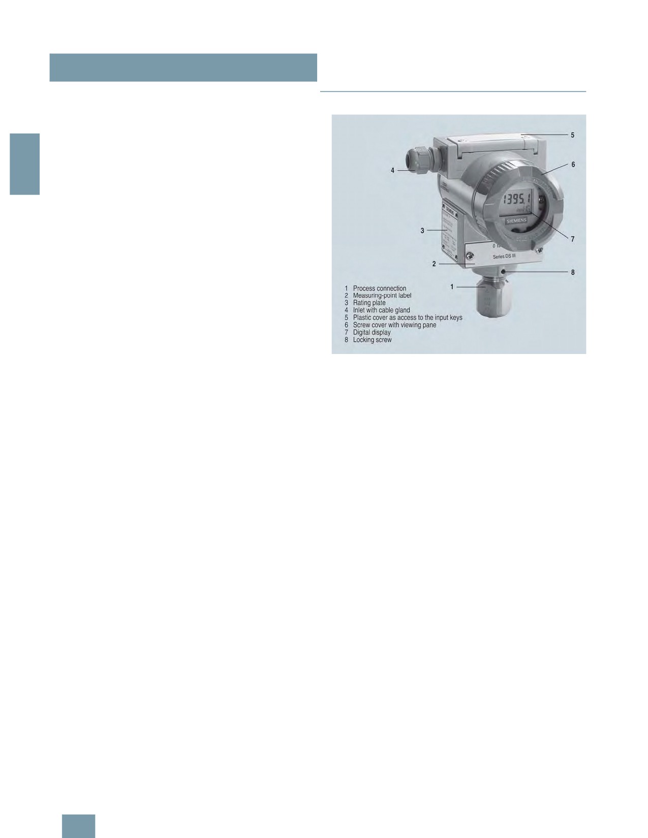
SITRANS P measuring instruments for pressure
Transmitters for gage, absolute and differential pressure, flow and level
DS III, DS III PA and DS III FF series
Technical description
Pressure transmitter for gage pressure
■Design
• Measured variable: Gage pressure of aggressive and non-ag-
gressive gases, vapors and liquids.
• Span (infinitely adjustable)
for DS III HART: 0.01 ... 400 bar g (0.145 ... 5802 psi g)
• Nominal measuring range
2
for DS III PA and FF: 1 ... 400 bar g (14.5 ... 5802 psi g)
Pressure transmitters for absolute pressure
• Measured variable: Absolute pressure of aggressive and non-
aggressive gases, vapors and liquids.
• Span (infinitely adjustable)
for DS III HART: 8.3 mbar a ... 100 bar a (0.12 ... 1450 psi a)
• Nominal measuring range
for DS III PA and FF: 250 mbar a ... 100 bar a
(3.63 ... 1450 psi a)
• There are two series:
- Gage pressure series
- Differential pressure series
Pressure transmitters for differential pressure and flow
• Measured variables:
- Differential pressure
- Small positive or negative pressure
- Flow q ~ √Δp (together with a primary differential pressure
device (see Chapter "Flow Meters"))
• Span (infinitely adjustable)
Front view
for DS III HART: 1 mbar ... 30 bar (0.0145 ... 435 psi)
The transmitter consists of various components depending on
• Nominal measuring range
the order. The possible versions are listed in the ordering infor-
for DS III PA and FF: 20 mbar ... 30 bar (0.29 ... 435 psi)
mation. The components described below are the same for all
transmitters.
Pressure transmitters for level
• Measured variable: Level of aggressive and non-aggressive
The rating plate (3, Figure "Front view") with the Order No. is lo-
liquids in open and closed vessels.
cated on the side of the housing. The specified number together
with the ordering information provide details on the optional de-
• Span (infinitely adjustable)
sign details and on the possible measuring range (physical
for DS III HART: 25 mbar ... 5 bar (0.363 ... 72.5 psi)
properties of built-in sensor element).
• Nominal measuring range
for DS III PA and FF: 250 mbar ... 5 bar (3.63 ... 72.5 psi)
The approval label is located on the opposite side.
• Nominal diameter of the mounting flange
The housing is made of die-cast aluminium or stainless steel pre-
- DN 80 or DN 100
cision casting. A round cover is screwed on at the front and rear
- 3 inch or 4 inch
of the housing. The front cover (6) can be fitted with a viewing
pane so that the measured values can be read directly on the
In the case of level measurements in open containers, the low-
digital display. The inlet (4) for the electrical connection is lo-
pressure connection of the measuring cell remains open (mea-
cated either on the left or right side. The unused opening on the
surement "compared to atmospheric").
opposite side is sealed by a blanking plug. The protective earth
In the case of measurements in closed containers, the lower-
connection is located on the rear of the housing.
pressure connection has to be connected to the container in or-
The electrical connections for the power supply and screen are
der to compensate the static pressure.
accessible by unscrewing the rear cover. The bottom part of the
The wetted parts are made from a variety of materials, depend-
housing contains the measuring cell with process connection
ing on the degree of corrosion resistance required.
(1). The measuring cell is prevented from rotating by a locking
screw (8). As the result of this modular design, the measuring
cell and the electronics can be replaced separately from each
other. The set parameter data are retained.
At the top of the housing is a plastic cover (5), which hides the
input keys.
2/64

SITRANS P measuring instruments for pressure
Transmitters for gage, absolute and differential pressure, flow and level
DS III, DS III PA and DS III FF series
Technical description
Operation of the electronics with PROFIBUS PA communica-
■Function
tion
Operation of the electronics with PROFIBUS PA communica-
tion
,
2
,
(
"
4
"
!
($ 2
++
,
"
2( >
4
+
++
,
,
+
,
,
,
7
>5
3
1
1 4
$
%
%
(
!
&
<
!
,
0
,
1
1 4
;
+
* ) (
3
%
(
!
&
?
&
11
1
0
,
5
5
1
;
&
!
& F
?
&
11
5
5
1
!
:
B
(
4
:
2( >
4
7
>5
3
$
%
<
!
* !
!
4
@
11
(
Function diagram of the electronics
2
& F
The bridge output voltage created by the sensor (1, Figure
"Function diagram of the electronics") is amplified by the instru-
ment amplifier (2) and digitized in the analog-to-digital converter
(3). The digital information is evaluated in the microcontroller, its
Function diagram of the electronics
linearity and temperature response corrected, and provided on
the PROFIBUS PA through an electrically isolated PA interface
The bridge output voltage created by the sensor (1, Figure
(7).
"Function diagram of the electronics") is amplified by the instru-
ment amplifier (2) and digitized in the analog-to-digital converter
The data specific to the measuring cell, the electronics data, and
(3). The digital information is evaluated in a microcontroller, its
the parameter data are stored in the two non-volatile memories
linearity and temperature response corrected, and converted in
(6). The first memory is linked with the measuring cell, the sec-
a digital-to-analog converter (5) into an output current of 4 to
ond with the electronics. This modular design means that the
20 mA.
electronics and the measuring cell can be replaced separately
from one another.
The diode circuit (10) protects against incorrect polarity.
Using the three input keys (8) you can parameterize the pressure
The data specific to the measuring cell, the electronics data, and
transmitter directly at the point of measurement. The input keys
the parameter data are stored in the two non-volatile memories
can also be used to control the view of the results, the error mes-
(6). The one memory is coupled to the measuring cell, the other
sages and the operating modes on the digital display (9).
to the electronics. As the result of this modular design, the elec-
tronics and the measuring cell can be replaced separately from
The results with status values and diagnostic values are trans-
each other.
ferred by cyclic data transmission on the PROFIBUS PA. Param-
eterization data and error messages are transferred by acyclic
Using the 3 input keys (8) you can parameterize the pressure
data transmission. Special software such as SIMATIC PDM is re-
transmitter directly at the point of measurement. The input keys
quired for this.
can also be used to control the view of the results, the error mes-
sages and the operating modes on the digital display (9).
The HART modem (7) permits parameterization using a protocol
according to the HART specification.
The pressure transmitters with spans ≤ 63 bar measure the input
pressure compared to atmosphere, transmitters with spans
≥ 160 bar compared to vacuum.
2/65

SITRANS P measuring instruments for pressure
Transmitters for gage, absolute and differential pressure, flow and level
DS III, DS III PA and DS III FF series
Technical description
Mode of operation of the FOUNDATION Fieldbus electronics
Mode of operation of the measuring cells
Measuring cell for gage pressure
,
2
BB
"
4
!
,
++
,
%
!
5
1
0
B
H
!
"
;
& F
+
Measuring cell for gage pressure, function diagram
,
The pressure pe is applied through the process connection (2,
Figure "Measuring cell for gage pressure, function diagram) to
,
7
>5
3
the measuring cell (1). This pressure is subsequently transmitted
1
1 4
$
%
further through the seal diaphragm (3) and the filling liquid (4) to
%
(
!
&
<
*
!
the silicon pressure sensor (5) whose measuring diaphragm is
0
,
;
+
then flexed. This changes the resistance of the four piezo-resis-
?
&
11
& F
tors fitted in the diaphragm in a bridge circuit. This change in re-
5
5
1
sistance results in a bridge output voltage proportional to the in-
!
put pressure.
:
BB
4
Measuring cell for gage pressure, with front-flush diaphragm for
Function diagram of the electronics
paper industry
The bridge output voltage created by the sensor (1, Figure
"Function diagram of the electronics") is amplified by the instru-
ment amplifier (2) and digitized in the analog-to-digital converter
(3). The digital information is evaluated in the microcontroller, its
linearity and temperature response corrected, and provided on
the FOUNDATION Fieldbus through an electrically isolated
FOUNDATION Fieldbus Interface (7).
The data specific to the measuring cell, the electronics data, and
the parameter data are stored in the two non-volatile memories
,
(6). The one memory is coupled to the measuring cell, the other
to the electronics. As the result of this modular design, the elec-
%
!
5
1
0
B
H
!
tronics and the measuring cell can be replaced separately from
;
each other.
& F
Using the three input keys (8) you can parameterize the pressure
transmitter directly at the point of measurement. The input keys
can also be used to control the view of the results, the error mes-
sages and the operating modes on the digital display (9).
The results with status values and diagnostic values are trans-
ferred by cyclic data transmission on the FOUNDATION
Measuring cell for gage pressure, with front-flush diaphragm for paper in-
Fieldbus. Parameterization data and error messages are trans-
dustry, function diagram
ferred by acyclic data transmission. Special software such as
National Instruments Configurator is required for this.
The pressure pe is applied through the process connection (2,
Figure "Measuring cell for gage pressure, with front-flush dia-
phragm for paper industry, function diagram") to the measuring
cell (1). This pressure is subsequently transmitted further
through the seal diaphragm (3) and the filling liquid (4) to the sil-
icon pressure sensor (5) whose measuring diaphragm is then
flexed. This changes the resistance of the four piezo-resistors fit-
ted in the diaphragm in a bridge circuit. This change in resis-
tance results in a bridge output voltage proportional to the input
pressure.
2/66
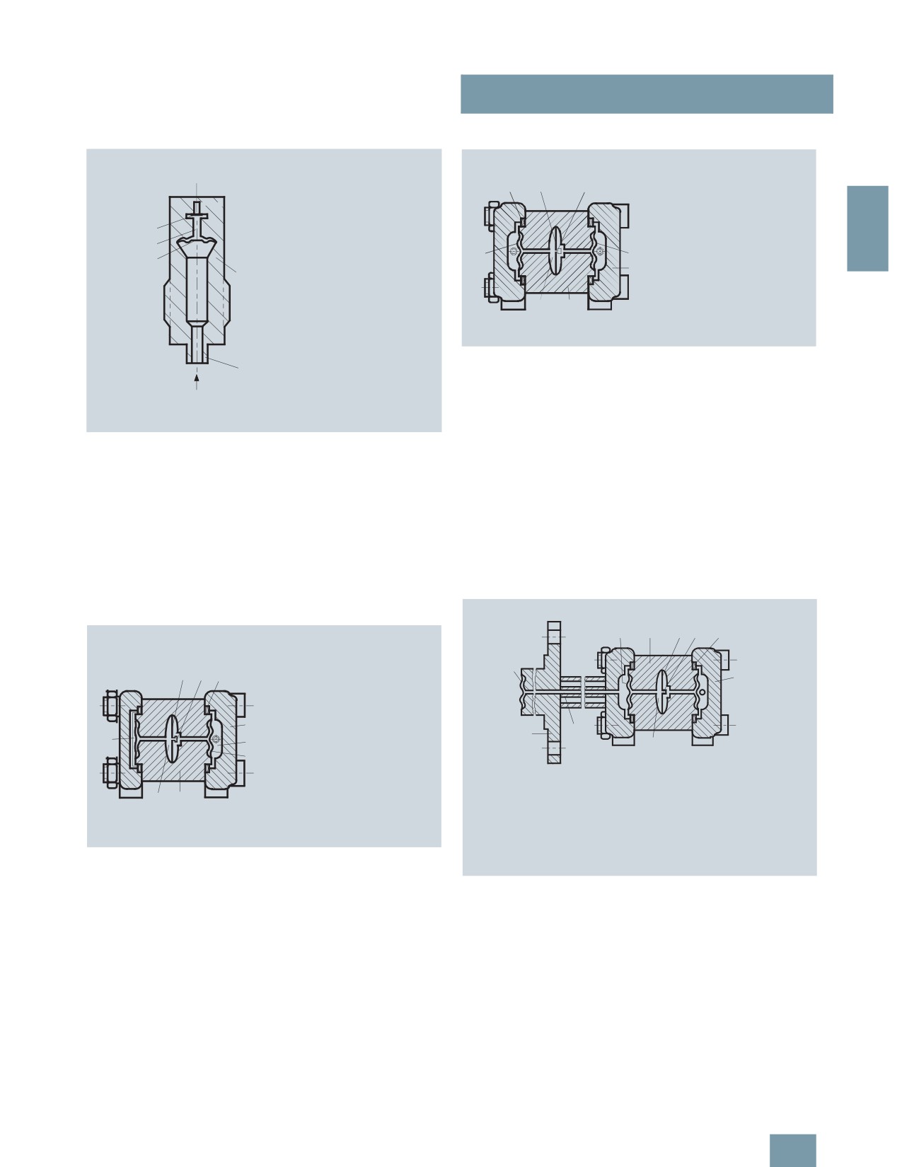
SITRANS P measuring instruments for pressure
Transmitters for gage, absolute and differential pressure, flow and level
DS III, DS III PA and DS III FF series
Technical description
Measuring cell for absolute pressure from gage pressure series
Measuring cell for differential pressure and flow
(
2
;
&
'
(
0
)
/
0
%
1
0.
2
'
3
,
%
!
5
1
0
B
H
!
;
F
(F
& F
Measuring cell for differential pressure and flow, function diagram
The differential pressure is transmitted through the seal dia-
phragms (1, Figure "Measuring cell for differential pressure and
flow, function diagram") and the filling liquid (7) to the silicon
pressure sensor (4).
The measuring diaphragm is flexed by the applied differential
Measuring cell for absolute pressure from the pressure series, function
pressure. This changes the resistance of the four piezo-resistors
diagram
fitted in the diaphragm in a bridge circuit. This change in resis-
The absolute pressure pe is transmitted through the seal dia-
tance results in a bridge output voltage proportional to the abso-
phragm (3, Figure "Measuring cell for absolute pressure from the
lute pressure.
gage pressure series, function diagram") and the filling liquid (4)
An overload diaphragm is installed to provide protection from
to the silicon absolute pressure sensor (5) whose measuring di-
overloads. If the measuring limits are exceeded, the overload di-
aphragm is then flexed. This changes the resistance of the four
aphragm (2) is flexed until the seal diaphragm rests on the body
piezo-resistors fitted in the diaphragm in a bridge circuit. This
of the measuring cell (7), thus protecting the silicon pressure
change in resistance results in a bridge output voltage propor-
sensor from overloads.
tional to the input pressure.
Measuring cell for level
Measuring cell for absolute pressure from differential pressure
series
4
&
1
&
!!
5
1
%
0
;
4
?
!
5
1
:
!
41
7
B
H
!
(F
& F
'
(
+
1
( .
2
0
4
0
&
(
5
'
3
)
0.
(0
3
/
'
( .
0.
0
Measuring cell for absolute pressure from differential pressure series,
function diagram
The input pressure pe is transmitted through the seal diaphragm
Measuring cell for level, function diagram
(6, Figure "Measuring cell for absolute pressure from differential
The input pressure (hydrostatic pressure) acts hydraulically on
pressure series, function diagram") and the filling liquid (8) to the
the measuring cell through the seal diaphragm on the mounting
silicon pressure sensor (3).
flange (2, Figure "Measuring cell for level, function diagram").
This differential pressure is subsequently transmitted further
The difference in pressure between the input pressure pe and
through the measuring cell (3) and the filling liquid (9) to the sil-
the reference vacuum (1) on the low-pressure side of the mea-
icon pressure sensor (6) whose measuring diaphragm is then
suring cell flexes the measuring diaphragm. The resistance of
flexed.
the four piezo-resistors fitted in the diaphragm in a bridge circuit
thus changes. This change in resistance results in a bridge out-
This changes the resistance of the four piezo-resistors fitted in
put voltage proportional to the absolute pressure.
the diaphragm in a bridge circuit.
This change in resistance results in a bridge output voltage pro-
An overload diaphragm is installed to provide protection from
portional to the differential pressure.
overloads. If the measuring limits are exceeded, the overload di-
aphragm (2) is flexed until the seal diaphragm rests on the body
An overload diaphragm is installed to provide protection from
of the measuring cell (7), thus protecting the silicon pressure
overloads. If the measuring limits are exceeded, the overload di-
sensor from overloads.
aphragm (2) is flexed until the seal diaphragm rests on the body
2/67

SITRANS P measuring instruments for pressure
Transmitters for gage, absolute and differential pressure, flow and level
DS III, DS III PA and DS III FF series
Technical description
of the measuring cell (7), thus protecting the silicon pressure
1) Cancel apart from write protection
sensor from overloads.
2) Only differential pressure
Parameterization DS III
Diagnostic functions for DS III HART
Depending on the version, there are a range of options for pa-
• Zero correction display
rameterizing the pressure transmitter and for setting or scanning
• Event counter
the parameters.
2
• Limit transmitter
Parameterization using the input keys (local operation)
• Saturation alarm
With the input keys you can easily set the most important param-
• Slave pointer
eters without any additional equipment.
• Simulation functions
Parameterization using HART communication
• Maintenance timer
Parameterization using HART communication is performed with
Available physical units of display for DS III HART
a HART communicator or a PC.
Table style: Technical specifications 2
Physical variable
Physical dimensions
Pressure (setting can also
Pa, MPa, kPa, bar, mbar, torr, atm, psi,
be made in the factory)
g/cm2, kg/cm2, inH2O, inH2O (4 °C),
> (=
%
###
mmH2O, ftH2O (20 °C), inHg, mmHg
1
Level (height data)
m, cm, mm, ft, in
2( >
Volume
m3, dm3, hl, yd3, ft3, in3, US gallon, lmp.
11
gallon, bushel, barrel, barrel liquid
Mass
g, kg, t, lb, Ston, Lton, oz
Communication between a HART communicator and a pressure transm.
Volume flow
m3/d, m3/h, m3/s, l/min, l/s, ft3/d, ft3/min,
ft3/s, US gallon/min, US gallon/s
When parameterizing with the HART communicator, the connec-
tion is made directly to the 2-wire system.
Mass flow
t/d, t/h, t/min, kg/d, kg/h, kg/min, kg/s, g/d,
g/h, g/min, g/s, lb/d, lb/h, lb/min, lb/s,
LTon/d, LTon/h, STon/d, STon/h, STon/min
Temperature
K, °C, °F, °R
Miscellaneous
%, mA
> (=
%
### ;
1
Parameterization through PROFIBUS PA interface
"
Fully digital communication through PROFIBUS PA, profile 3.0, is
2( >
particularly user-friendly. The PROFIBUS puts the DS III PA is in
1 ! 1
connection with a process control system, e.g. SIMATIC PSC 7.
Communication is possible even in a potentially explosive envi-
%
ronment.
For parameterization through PROFIBUS you need suitable soft-
HART communication between a PC communicator and a pressure
ware, e.g. SIMATIC PDM (Process Device Manager).
transmitter
Parameterization through FOUNDATION Fieldbus Interface
When parameterizing with a PC, the connection is made through
Fully digital communication through FOUNDATION Fieldbus is
a HART modem.
particularly user-friendly. Through the FOUNDATION Fieldbus
The signals needed for communication in conformity with the
the DS III FF is connected to a process control system. Commu-
HART 5.x or 6.x protocols are superimposed on the output cur-
nication is possible even in a potentially explosive environment.
rent using the Frequency Shift Keying (FSK) method.
For parameterization through the FOUNDATION Fieldbus you
Adjustable parameters, DS III HART
need suitable software, e.g. National Instruments Configurator.
Parameters
Input keys
HART com-
Adjustable parameters for DS III PA and FF
(DS III HART) munication
Parameters
Input keys
PROFIBUS PA and
Start of scale
x
x
(DS III HART) FOUNDATION
Full-scale value
x
x
Fieldbus interface
Electrical damping
x
x
Electrical damping
x
x
Start-of-scale value without application x
x
Zero adjustment (correction of x
x
of a pressure ("Blind setting")
position)
Full-scale value without application of a x
x
Key and/or function disabling x
x
pressure ("Blind setting")
Source of measured-value dis- x
x
Zero adjustment
x
x
play
Current transmitter
x
x
Physical dimension of display x
x
Fault current
x
x
Position of decimal point
x
x
Disabling of keys, write protection
x
x1)
Bus address
x
x
Type of dimension and actual dimension x
x
Adjustment of characteristic
x
x
Characteristic (linear / square-rooted)
x2)
x2)
Input of characteristic
x
Input of characteristic
x
Freely-programmable LCD
x
Freely-programmable LCD
x
Diagnostics functions
x
Diagnostics functions
x
2/68

SITRANS P measuring instruments for pressure
Transmitters for gage, absolute and differential pressure, flow and level
DS III, DS III PA and DS III FF series
Technical description
Diagnostic functions for DS III PA and FF
• Event counter
• Slave pointer
• Maintenance timer
• Simulation functions
• Display of zero correction
2
• Limit transmitter
• Saturation alarm
Physical dimensions available for the display
Physical variable
Physical dimensions
Pressure (setting can also MPa, kPa, Pa, bar, mbar, torr, atm, psi,
be made in the factory)
g/cm2, kg/cm2, mmH2O, mmH2O (4 °C),
inH2O, inH20 (4 °C), ftH2O (20 °C), mmHg,
inHg
Level (height data)
m, cm, mm, ft, in, yd
Volume
m3, dm3, hl, yd3, ft3, in3, US gallon, lmp.
gallon, bushel, barrel, barrel liquid
Volume flow
m3/s, m3/min, m3/h, m3/d, l/s, l/min, l/h, l/
d, Ml/d, ft3/s, ft3/min, ft3/h, ft3/d, US gal-
lon/s, US gallon/min, US gallon/h, US gal-
lon/d, bbl/s, bbl/min, bbl/h, bbl/d
Mass flow
g/s, g/min, g/h, g/d, kg/s, kg/min, kg/h,
kg/d, t/s, t/min, t/h, /t/d, lb/s, lb/min, lb/h,
lb/d, STon/s, STon/min, STon/h, STon/d,
LTon/s, LTon/min, LTon/h, LTon/d
Total mass flow
t, kg, g, lb, oz, LTon, STon
Temperature
K, °C, °F, °R
Miscellaneous
%
2/69

SITRANS P measuring instruments for pressure
Transmitters for gage, absolute and differential pressure, flow and level
DS III series
for gage pressure
■ Technical specifications
SITRANS P, DS III series for gage pressure
HART
PROFIBUS PA or FOUNDATION Fieldbus
Input
2
Measured variable
Gage pressure
Spans (infinitely adjustable) or
Span
Max. perm. test pres-
Nominal measuring
Max. perm. test pres-
nominal measuring range and
sure
range
sure
max. permissible test pressure
0.01 ... 1 bar g
6 bar g
1 bar g
6 bar g
(0.145 ... 14.5 psi g)
(87 psi g)
(14.5 psi g)
(87 psi g)
0.04 ... 4 bar g
10 bar g
4 bar g
10 bar g
(0.58 ... 58 psi g)
(145 psi g)
(58 psi g)
(145 psi g)
0.16 ... 16 bar g
32 bar g
16 bar g
32 bar g
(2.23 ... 232 psi g)
(464 psi g)
(232 psi g)
(464 psi g)
0.6 ... 63 bar g
100 bar g
63 bar g
100 bar g
(9.14 ... 914 psi g)
(1450 psi g)
(914 psi g)
(1450 psi g)
1.6 ... 160 bar g
250 bar g
160 bar g
250 bar g
(23.2 ... 2320 psi g)
(3626 psi g)
(2320 psi g)
(3626 psi g)
4.0 ... 400 bar g
600 bar g
400 bar g
600 bar g
(58 ... 5802 psi g)
(8700 psi g)
(5802 psi g)
(8700 psi g)
7.0 ... 700 bar g
800 bar g
700 bar g
800 bar g
(102 ... 10153 psi g)
(11603 psi g)
(10153 psi g)
(11603 psi g)
Lower measuring limit
• Measuring cell with silicone oil filling
30 mbar a (0.435 psi a)
• Measuring cell with inert filling liquid
30 mbar a (0.435 psi a)
Upper measuring limit
100% of max. span (max. 160 bar g (2320 psi g) with oxygen measurement and inert liquid)
Output
Output signal
4 ... 20 mA
Digital PROFIBUS PA or FOUNDATION Fieldbus
signal
• Lower limit (infinitely adjustable)
3.55 mA, factory preset to 3.84 mA
-
• Upper limit (infinitely adjustable)
23 mA, factory preset to 20.5 mA or optionally set
-
to 22.0 mA
Load
• Without HART communication
RB ≤ (UH - 10.5 V)/0.023 A in Ω,
-
UH : Power supply in V
• With HART communication
RB = 230 ... 500 Ω (SIMATIC PDM) or
-
RB = 230 ... 1100 Ω (HART Communicator)
Physical bus
-
IEC 61158-2
With polarity reversal protection
-
Yes
Accuracy
To EN 60770-1
Reference conditions
Increasing characteristic, start-of-scale value 0 bar, stainless steel seal diaphragm, silicone oil filling,
(All error data refer always refer to the set
room temperature 25 °C (77 °F)) r: Span ratio (r = max. span/set span)
span)
Error in measurement and fixed-point setting
(including hysteresis and repeatability)
• Linear characteristic
≤ 0,075%
- r ≤ 10
≤ (0.0029 ⋅ r + 0.071)%
-
10 < r ≤ 30
≤ (0.0045 ⋅ r + 0.071)%
-
30 < r ≤ 100
≤ (0.005 ⋅ r + 0.05)%
Long-term drift (temperature change ±30 °C
≤ (0.25 ⋅ r)% every 5 years
≤ 0.25% every 5 years
(±54 °F))
Influence of ambient temperature
• at -10 ... +60 °C (14 ... 140 °F)
≤ (0.08 ⋅ r + 0.1)%
≤ 0,3%
(at 700 bar: ≤ (0.1 ⋅ r + 0.2)%)
• at -40 ... -10 °C and +60 ... +85 °C
≤ (0.1 ⋅ r + 0.15)%/10 K
≤ 0.25%/10 K
(-40 ... +14 °F and 140 ... 185 °F)
Measured Value Resolution
-
3 ⋅ 10-5 of nominal measuring range
2/70

SITRANS P measuring instruments for pressure
Transmitters for gage, absolute and differential pressure, flow and level
DS III series
for gage pressure
SITRANS P, DS III series for gage pressure
HART
PROFIBUS PA or FOUNDATION Fieldbus
Rated operating conditions
Degree of protection (to EN 60529)
IP65
Process temperature
2
• Measuring cell with silicone oil filling
-40 ... +100 °C (-40 ... +212 °F)
• Measuring cell with inert filling liquid
-20 ... +100 °C (-4 ... +212 °F)
• In conjunction with dust explosion protec-
-20 ... +60 °C (-4 ... +140 °F)
tion
Ambient conditions
• Ambient temperature
- Digital indicators
-30 ... +85 °C (-22 ... +185 °F)
• Storage temperature
-50 ... +85 °C (-58 ... +185 °F)
• Climatic class
- Condensation
Permissible
• Electromagnetic compatibility
- Emitted interference and interference
To EN 61326 and NAMUR NE 21
immunity
Design
Weight (without options)
≈ 1.5 kg (≈ 3.3 lb)
Housing material
Poor in copper die-cast aluminium, GD-AlSi12 or stainless steel precision casting, mat. No. 1.4408
Wetted parts materials
• Connection shank
Stainless steel, mat. No. 1.4404/316L or Hastelloy C4, mat. No. 2.4610
• Oval flange
Stainless steel, mat. No. 1.4404/316L
• Seal diaphragm
Stainless steel, mat. No. 1.4404/316L or Hastelloy C276, mat. No. 2.4819
Measuring cell filling
Silicone oil or inert filling liquid (max. 160 bar (2320 psi g) with oxygen measurement)
Process connection
Connection shank G½A to DIN EN 837-1, female thread ½ -14 NPT or oval flange (PN 160
(MWP 2320 psi g)) to DIN 19213 with mounting thread M10 or 7/16-20 UNF to EN 61518
Material of the mounting bracket
• Steel
Sheet steel, Mat. No. 1.0330, chrome-plated
• Stainless steel
Stainless steel, Mat. No. 1.4301 (SS304)
Power supply UH
Supplied through bus
Terminal voltage on transmitter
10.5 ... 45 V DC
-
10.5 ... 30 V DC in intrinsically-safe mode
Separate 24 V power supply necessary
-
No
Bus voltage
• Not Ex
-
9 ...32 V
• With intrinsically-safe operation
-
9 ...24 V
Current consumption
• Basic current (max.)
-
12.5 mA
• Startup current ≤ basic current
-
Yes
• Max. current in event of fault
-
15.5 mA
Fault disconnection electronics (FDE) avail-
-
Yes
able
2/71
SITRANS P measuring instruments for pressure
Transmitters for gage, absolute and differential pressure, flow and level
DS III series
for gage pressure
SITRANS P, DS III series for gage pressure
HART
PROFIBUS PA or FOUNDATION Fieldbus
Certificate and approvals
Classification according to pressure equip-
For gases of fluid group 1 and liquids of fluid group 1; complies with requirements of Article 3, para-
ment directive (DRGL 97/23/EC)
graph 3 (sound engineering practice)
2
Explosion protection
• Intrinsic safety "i"
PTB 99 ATEX 2122
- Identification
Ex II 1/2 G EEx ia/ib IIB/IIC T6
- Permissible ambient temperature
-40 ... +85 °C (-40 ... +185 °F) temperature class T4;
-40 ... +70 °C (-40 ... +158 °F) temperature class T5;
-40 ... +60 °C (-40 ... +140 °F) temperature class T6
- Connection
To certified intrinsically-safe circuits with maxi-
FISCO supply unit:
mum values:
Uo = 17.5 V, Io = 380 mA, Po = 5.32 W
Ui = 30 V, Ii = 100 mA,
Linear barrier:
Pi = 750 mW; Ri = 300 Ω
Uo = 24 V, Io = 250 mA, Po = 1.2 W
- Effective internal inductance/capacitance
L
i
= 0.4 mH, Ci = 6 nF
L
i
= 7 μH, Ci = 1.1 nF
• Explosion-proof "d"
PTB 99 ATEX 1160
- Identification
Ex II 1/2 G EEx d IIC T4/T6
- Permissible ambient temperature
-40 ... +85 °C (-40 ... +185 °F) temperature class T4;
-40 ... +60 °C (-40 ... +140 °F) temperature class T6
- Connection
To circuits with values: UH = 10.5 ... 45 V DC
To circuits with values: UH = 9 ... 32 V DC
• Dust explosion protection for zone 20
PTB 01 ATEX 2055
- Identification
Ex II 1 D IP65 T 120 °C
Ex II 1/2 D IP65 T 120 °C
- Permissible ambient temperature
-40 ... +85 °C (-40 ... +185 °F)
- Max.surface temperature
120 °C (248 °F)
- Connection
To certified intrinsically-safe circuits with maxi-
FISCO supply unit:
mum values:
Uo = 17.5 V, Io = 380 mA, Po = 5.32 W
Ui = 30 V, Ii = 100 mA,
Linear barrier:
Pi = 750 mW, Ri = 300 Ω
Uo = 24 V, Io = 250 mA, Po = 1.2 W
- Effective internal inductance/capacitance
L
i
= 0.4 mH, Ci = 6 nF
L
i
= 7 μH, Ci = 1.1 nF
• Dust explosion protection for zone 21/22
PTB 01 ATEX 2055
- Identification
Ex II 2 D IP65 T 120 °C
- Connection
To circuits with values: UH = 10.5 ... 45 V DC;
To circuits with values: UH = 9 ... 32 V DC;
Pmax = 1.2 W
Pmax = 1.2 W
• Type of protection "n" (zone 2)
TÜV 01 ATEX 1696 X
Planned
- Identification
Ex II 3 G EEx nA L IIC T4/T5/T6
-
• Explosion protection to FM
Certificate of Compliance 3008490
- Identification (XP/DIP) or (IS); (NI)
CL I, DIV 1, GP ABCD T4...T6; CL II, DIV 1, GP EFG; CL III; CL I, ZN 0/1 AEx ia IIC T4...T6; CL I,
DIV 2, GP ABCD T4...T6; CL II, DIV 2, GP FG; CL III
• Explosion protection to CSA
Certificate of Compliance 1153651
- Identification (XP/DIP) or (IS)
CL I, DIV 1, GP ABCD T4...T6; CL II, DIV 1, GP EFG; CL III; Ex ia IIC T4...T6; CL I, DIV 2, GP ABCD
T4...T6; CL II, DIV 2, GP FG; CL III
2/72

SITRANS P measuring instruments for pressure
Transmitters for gage, absolute and differential pressure, flow and level
DS III series
for gage pressure
HART communication
Communication FOUNDATION Fieldbus
HART communication
230 ... 1100 Ω
Function blocks
3 function blocks analog input,
1 function block PID
Protocol
HART Version 5.x
• Analog input
Software for computer
SIMATIC PDM
- Adaptation to customer-specif-
Yes, linearly rising or falling char-
ic process variables
acteristic
2
PROFIBUS PA communication
- Electrical damping T63 , adjust-
0 ... 100 s
Simultaneous communication with
4
able
master class 2 (max.)
- Simulation function
Output/input (can be locked within
The address can be set using
Configuration tool or local opera-
the device with a bridge)
tion (standard setting address
126)
- Failure mode
Can be parameterized (last good
value, substitute value, incorrect
Cyclic data usage
value)
• Output byte
5 (one measuring value) or
- Limit monitoring
Yes, one upper and lower warning
10 (two measuring values)
limit and one alarm limit respec-
• Input byte
0, 1, or 2 (register operating mode
tively
and reset function for metering)
- Square-rooted characteristic
Yes
Internal preprocessing
for flow measurement
Device profile
PROFIBUS PA Profile for Process
• PID
Standard FF function block
Control Devices Version 3.0,
• Physical block
1 Resource block
Class B
Transducer blocks
1 transducer block Pressure with
Function blocks
2
calibration, 1 transducer block
• Analog input
LCD
- Adaptation to customer-specif-
Yes, linearly rising or falling char-
• Pressure transducer block
ic process variables
acteristic
-
Can be calibrated by applying
Yes
- Electrical damping T63 , adjust-
0 ... 100 s
two pressures
able
-
Monitoring of sensor limits
Yes
- Simulation function
Input /Output
-
Simulation function: Measured
Constant value or over parameter-
- Failure mode
Can be parameterized (last good
pressure value, sensor temper-
izable ramp function
value, substitute value, incorrect
ature and electronics tempera-
value)
ture
- Limit monitoring
Yes, one upper and lower warning
limit and one alarm limit respec-
tively
• Register (totalizer)
Can be reset, preset, optional
direction of counting, simulation
function of register output
- Failure mode
Can be parameterized (summation
with last good value, continuous
summation, summation with incor-
rect value)
- Limit monitoring
One upper and lower warning limit
and one alarm limit respectively
• Physical block
1
Transducer blocks
2
• Pressure transducer block
- Can be calibrated by applying
Yes
two pressures
- Monitoring of sensor limits
Yes
- Specification of a container
Max. 30 nodes
characteristic with
- Square-rooted characteristic
Yes
for flow measurement
- Gradual volume suppression
Parameterizable
and implementation point of
square-root extraction
- Simulation function for mea-
Constant value or over parameter-
sured pressure value and sen-
izable ramp function
sor temperature
2/73

SITRANS P measuring instruments for pressure
Transmitters for gage, absolute and differential pressure, flow and level
DS III series
for gage pressure
Selection and Ordering data
Order No.
Selection and Ordering data
Order No.
SITRANS P pressure transmitters for gage
7MF4033 -
SITRANS P pressure transmitters for gage
7MF4033 -
pressure, series DS III HART
pressure, series DS III HART
77777-7777
77777-7777
Measuring cell filling Measuring cell
Display
cleaning
• Without indicator
0
2
Silicone oil
Standard
}
1
• Without visible digital indicator (digital indicator }
1
Inert liquid1)
Grease-free
3
hidden, setting: mA)
6
Span
• With visible digital indicator, setting: mA
0.01 ... 1 bar g
(0.15 ... 14.5 psi g)
}
B
7
• with customer-specific digital indicator
0.04 ... 4 bar g
(0.58 ... 58 psi g)
}
C
(setting as specified, Order code "Y21" or "Y22"
0.16 ... 16 bar g
(2.32 ... 232 psi g)
}
D
required)
0.63 ... 63 bar g
(9.14 ... 914 psi g)
}
E
}Available ex stock
1.6 ... 160 bar g
(23.2 ... 2320 psi g)
}
F
Power supply units see "SITRANS I power supply units and isolation
4.0 ... 400 bar g
(58.0 ... 5802 psi g)
}
G
amplifiers".
7,0 ... 700 bar g
(102.0 ...10153 psi g)
}
J
Factory-mounting of shut-off valves and valve manifolds see page
Wetted parts materials
2/142.
Seal diaphragm
Process connection
Included in delivery of the device:
Stainless steel
Stainless steel
}
A
• Brief instructions (Leporello)
Hastelloy
Stainless steel
B
• CD-ROM with detailed documentation
Hastelloy
Hastelloy
C
1) For oxygen application, add Order code E10.
Version as diaphragm seal 2) 3)
Y
2) When the manufacture’s certificate M (calibration certificate) has to be
Process connection
ordered for transmitters with diaphragm seals, it is recommended only to
order this certificate exclusively with the diaphragm seals. The measuring
• Connection shank G½B to EN 837-1
}
0
accuracy of the total combination is certified here.
• Female thread ½-14 NPT
1
3) Whe the acceptance test certificate 3.1 for transmitters with direct-con-
• Oval flange made of stainless steel
nected diaphragm seals is ordered, this certificate must also be ordered
- Mounting thread 7/16-20 UNF to EN 61518
2
with the corresponding seals.
4) Not together with Electrical connection „Screwed gland Pg 13.5“ and
- Mounting thread M10 to DIN 19213
3
„Han7D plug“.
- Mounting thread M12 to DIN 19213
4
5) Without cable gland, with blanking plug
• Male thread M20 x 1,5
5
6) With enclosed cable gland EEx ia and blanking plug
• Male thread ½-14 NPT
6
7) Not together with type of protection "Explosion-proof" and type of protection
"Ex nA".
Non-wetted parts materials
8) Cannot be used together with the following types of protection:
• Housing made of die-cast aluminium
}
0
"Explosion-proof" and "Intrinsic safety and explosion-proof"
• Housing stainless steel precision casting4)
3
Version
• Standard version
1
• International version, English label inscriptions, }
2
documentation in 5 languages on CD
Explosion protection
• Without
A
• With ATEX, Type of protection:
- "Intrinsic safety (EEx ia)"
B
- "Explosion-proof (EEx d)"5)
D
- "Intrinsic safety and explosion-proof enclosure
P
(EEx ia + EEx d)"6)
- "Ex nA/nL (zone 2)"
E
- "Intrinsic safety, explosion-proof enclosure and}
R
dust explosion protection (EEx ia + EEx d +
Zone 1D/2D)"6)
• With FM + CSA, Type of protection:
- "Intrinsic safety and explosion-proof
NC
(is + xp)"5)
Electrical connection / cable entry
• Screwed gland Pg 13.5 (adapter)7)
A
• Screwed gland M20x1.5
}
B
• Screwed gland ½-14 NPT
C
• Han 7D plug (plastic housing) incl. mating
D
connector7)
• M12 connector (metal)8)
F
2/74

SITRANS P measuring instruments for pressure
Transmitters for gage, absolute and differential pressure, flow and level
DS III series
for gage pressure
Selection and Ordering data
Order No.
Selection and Ordering data
Order No.
SITRANS P pressure transmitters for gage
SITRANS P pressure transmitters for gage
pressure
pressure
DS III PA (PROFIBUS PA) series
7MF4034 -
DS III PA (PROFIBUS PA) series
7MF4034 -
DS III FF series (FOUNDATION Fieldbus)
7MF4035 -
DS III FF series (FOUNDATION Fieldbus)
7MF4035 -
77777-7777
77777-7777
2
Measuring cell filling Measuring cell
Display
cleaning
• Without indicator
0
Silicone oil
Standard
1
• Without visible digital indicator (digital indicator }
1
Inert liquid1)
Grease-free
3
hidden, setting: mA)
• With visible digital indicator
6
Nominal measuring range
• With customer-specific digital indicator (setting
7
1 bar g
(14.5 psi g)
B
as specified, Order code "Y21" or required)
4 bar g
(58 psi g)
C
16 bar g
(232 psi g)
D
Factory-mounting of shut-off valves and valve manifolds see page
2/142.
63 bar g
(914 psi g)
E
160 bar g
(2320 psi g)
F
The device is delivered together with brief instructions (Leporello) and a
CD-ROM containing detailed documentation.
400 bar g
(5802 psi g)
G
700 bar g
(10153 psi g)
J
1) For oxygen application, add Order code E10.
Wetted parts materials
2) When the manufacture’s certificate M (calibration certificate) has to be
ordered for transmitters with diaphragm seals, it is recommended only to
Seal diaphragm
Process connection
order this certificate exclusively with the diaphragm seals. The measuring
Stainless steel
Stainless steel
A
accuracy of the total combination is certified here.
3) Whe the acceptance test certificate 3.1 for transmitters with direct-con-
Hastelloy
Stainless steel
B
nected diaphragm seals is ordered, this certificate must also be ordered
Hastelloy
Hastelloy
C
with the corresponding seals.
Version as diaphragm seal2) 3)
Y
4) Without cable gland, with blanking plug.
5) With enclosed cable gland EEx ia and blanking plug.
Process connection
6) Cannot be used together with the following types of protection:
• Connection shank G½A to EN 837-1
0
"Explosion-proof" and "Intrinsic safety and explosion-proof"
• Female thread ½-14 NPT
1
• Oval flange made of stainless steel
- Mounting thread 7/16-20 UNF to EN 61518
2
- Mounting thread M10 to DIN 19213
3
- Mounting thread M12 nach DIN 19213
4
• Male thread M20 x 1,5
5
• Male thread ½-14 NPT
6
Non-wetted parts materials
• Housing made of die-cast aluminium
0
• Housing stainless steel precision casting
3
Version
• Standard version
1
• International version, English label inscriptions,
2
documentation in 5 languages on CD
Explosion protection
• Without
A
• With ATEX, Type of protection:
- "Intrinsic safety (EEx ia)"
B
- "Explosion-proof (EEx d)"4)
D
- "Intrinsic safety and explosion-proof enclosure
P
(EEx ia + EEx d)"5)
- "Ex nA/nL (zone 2)"
E
- "Intrinsic safety, explosion-proof enclosure and
R
dust explosion protection (EEx ia + EEx d +
Zone 1D/2D)"6) (not for DS III FF)
• With FM + CSA, Type of protection:
- "Intrinsic safety and explosion-proof
NC
(is + xp)"5)
Electrical connection / cable entry
• Screwed gland M20x1.5
B
• Screwed gland ½-14 NPT
C
• Plug M12 (metal)6)
F
2/75

SITRANS P measuring instruments for pressure
Transmitters for gage, absolute and differential pressure, flow and level
DS III series
for gage pressure
Selection and Ordering data
Order code
Selection and Ordering data
Order code
Further designs
HART
PA
FF
Additional data
HART
PA
FF
Add "-Z" to Order No. and specify Order code.
Add "-Z" to Order No. and specify Order
code.
Pressure transmitter with mounting
bracket made of:
Measuring range to be set
Y01
• Steel
A01
Specify in plain text (max. 5 digits):
2
• Stainless steel
A02
Y01: ... up to ... mbar, bar, kPa, MPa, psi
Plug
Measuring point number (TAG No.)
Y15
• Han 7D (metal, gray)
A30
Max. 16 characters, specify in plain text:
Y15:
• Han 8U (instead of Han 7D)
A31
Cable sockets for M12 connectors (metal)
A50
Measuring point text
Y16
Max. 27 characters, specify in plain text:
Rating plate inscription
Y16:
(instead of German)
Entry of HART address (TAG)
Y17
• English
B11
Max. 8 characters, specify in plain text:
• French
B12
Y17:
• Spanish
B13
• Italian
B14
Setting of pressure indication in pressure
Y21
units
English rating plate
B21
Specify in plain text (standard setting: mA):
Pressure units in inH2O or psi
Y21: mbar, bar, kPa, MPa, psi, ...
Note:
Quality inspection certificate (Factory cali-
C11
The following pressure units can be selected:
bration) to IEC 60770-21)
bar, mbar, mm H2O*), inH2O*), ftH2O*),
Acceptance test certificate2)
C12
mmHG, inHG, psi, Pa, kPa, MPa, g/cm2,
To EN 10204-3.1
kg/cm2, Torr, ATM oder %
*) ref. temperature 20 °C
Factory certificate
C14
To EN 10204-2.2
Setting of pressure indication in
Y22 +
non-pressure units
Y01
"Functional Safety (SIL)" certificate
C20
Specify in plain text:
"PROFIsafe“ certificate and protocol
C21
Y22:
up to
l/min, m3/h, m, USgpm, ...
(specification of measuring range in
Setting of upper limit of output signal to
D05
pressure units "Y01" is essential, unit with
22.0 mA
max. 5 characters)
Manufacturer's declaration acc. to NACE
D07
Preset bus address
Y25
Type of protection IP68
D12
(possible between 1 and 126)
(not together with 7D/
Specify in plain text:
Han 8U plug, cable gland Pg 13.5)
Y25:
Digital indicator alongside the input keys
D27
Only "Y01", "Y21", "Y22", "Y25" and "D05" can be factory preset
(only together with the devices 7MF4033-
= available
....0-.A.6 or -.A.7-Z, Y21 or Y22 + Y01)
Ordering example
Supplied with oval flange
D37
Item line:
7MF4033-1EA00-1AA7-Z
(1 item), PTFE packing and screws in thread
B line:
A01 + Y01 + Y21
of oval flange
C line:
Y01: 10 ... 20 bar (145 ... 290
psi)
Use in or on zone 1D/2D
E01
C line:
Y21: bar (psi)
(only together with type of protection
"Intrinsic safety (EEx ia)")
Use on zone 0
E02
(only together with type of protection
"Intrinsic safety (EEx ia)")
Oxygen application
E10
(max. 120 bar g (1740 psi g) at 60°C (140 °F)
for oxygen measurement and inert liquid)
Explosion-proof "Intrinsic safety" to
E25
INMETRO (Brazil)
(only for transmitter 7MF4...-
-.B..)
Explosion-proof "Intrinsic safety" to
E55
NEPSI (China)
(only for transmitter 7MF4...-
-.B..)
Explosion protection "Explosion-proof" to
E56
NEPSI (China)
(only for transmitter 7MF4...-
-.D..)
Explosion-proof "Zone 2" to NEPSI (China) E57
(only for transmitter 7MF4...-
-.E..)
1) When the manufacture’s certificate M (calibration certificate) has to be
ordered for transmitters with diaphragm seals, it is recommended only to
order this certificate exclusively with the diaphragm seals. The measuring
accuracy of the total combination is certified here.
2) Whe the acceptance test certificate 3.1 for transmitters with direct-con-
nected diaphragm seals is ordered, this certificate must also be ordered
with the corresponding seals.
2/76

SITRANS P measuring instruments for pressure
Transmitters for gage, absolute and differential pressure, flow and level
DS III series
for gage pressure
■Dimensional drawings
15
55
144 (5.67)
4)
(0.6)
(2.2)
approx 30 (1.2)
100 (3.94)
51
28
74
6
2
(2.0)
(1.1)
(2.9)
2
3
1)
1)
4
8
5
1
123 (4.8)
5)
7
min. 90 (3.6)
105 (4.1)
ø 50 ... 60
(1.97 ... 2.36)
1 Process connection:
- ½-14 NPT,
- connection shank G½B or
- oval flange
2 Blanking plug
3 Electrical connection:
- screwed gland M20x1,5 4),
- screwed gland ½-14 NPT or
- PROFIBUS-Stecker M12 3) 4)
4 Terminal side
5 Electronic side, digital display (longer overall
length for cover with window)
6 Protective cover over keys
1) Allow approx. 20 mm (0.79 inch) thread length in addition
7 Mounting bracket (option)
2) Minimum distance for rotating
8 Screw cover - safety bracket (only for type of protection
3) Not with type of protection "Explosion-proof enclosure"
"Explosion-proof enclosure", not shown in the drawing)
4) Not with type of protection "FM + CSA"
SITRANS P pressure transmitters, DS III HART series for gage pressure, dimensions in mm (inch)
2/77

SITRANS P measuring instruments for pressure
Transmitters for gage, absolute and differential pressure, flow and level
DS III series
for gage pressure
15
55
144 (5.67)
4)
100 (3.94)
(0.6)
(2.2)
ca. 30 (1.2)
51
28
ca. 96 (3.78)
74
6
2
(2.0)
(1.1)
(2.9)
2
3
3
1)
1)
4
8
5
1
123 (4.8)
5)
7
min. 90 (3.6)
105 (4.1)
ø 50 ... 60
(1.97 ... 2.36)
1 Process connection:
- ½-14 NPT,
- onnection shankG½B or
- oval flange
2 Blanking plug
3 Electrical connection:
- screwed gland Pg 13,5 (adapter)2) 3),
- screwed gland M20x1,5 3),
- screwed gland ½-14 NPT or
- Han 7D/ Han 8U 2) 3) plug
4 Terminal side
5 Electronic side, digital display (longer overall
length for cover with window)
1) Allow approx. 20 mm (0.79 inch) thread length to permit unscrewing
6 Protective cover over keys
2) Not with type of protection "Explosion-proof enclosure"
7 Mounting bracket (option)
3) Not with type of protection "FM + CSA" [is + xp]"
8 Screw cover - safety bracket (only for type of protection
4) For Pg 13,5 with adapter approx. 45 mm (1.77 inch)
"Explosion-proof enclosure", not shown in the drawing)
5) Minimum distance for rotating
SITRANS P pressure transmitters, DS III PA and FF series for gage pressure, dimensions in mm (inch)
2/78

SITRANS P measuring instruments for pressure
Transmitters for gage, absolute and differential pressure, flow and level
DS III series for gage and absolute pressure,
with front-flush diaphragm
■ Technical specifications
SITRANS P, DS III series for gage and absolute pressure, with front-flush diaphragm
HART
PROFIBUS PA or FOUNDATION Fieldbus
Input gage pressure, with front-flush
diaphragm
2
Measured variable
Gage pressure, flush-mounted
Spans (infinitely adjustable) or
Span
Max. perm. test pres-
Nominal measuring
Max. perm. test pres-
nominal measuring range and
sure
range
sure
max. permissible test pressure
0.01 ... 1 bar g
6 bar g
1 bar g
6 bar g
(0.145 ... 14.5 psi g)
(87 psi g)
(14.5 psi g)
(87 psi g)
0.04 ... 4 bar g
10 bar g
4 bar g
10 bar g
(0.58 ... 58 psi g)
(145 psi g)
(58 psi g)
(145 psi g)
0.16 ... 16 bar g
32 bar g
16 bar g
32 bar g
(2.23 ... 232 psi g)
(464 psi g)
(232 psi g)
(464 psi g)
0.6 ... 63 bar g
100 bar g
63 bar g
100 bar g
(9.14 ... 914 psi g)
(1450 psi g)
(914 psi g)
(1450 psi g)
Lower measuring limit
-100 mbar a (-1.45 psi a)
Upper measuring limit
100% of max. span
100% of nominal measuring range
Input absolute pressure, with front-flush
diaphragm
Measured variable
Absolute pressure, flush-mounted
Spans (infinitely adjustable) or
Span
Max. perm. test pres-
Nominal measuring
Max. perm. test pres-
nominal measuring range and
sure
range
sure
max. permissible test pressure
43 ... 1300 mbar a
10 bar a
1300 mbar a
10 bar a
(0.62 ... 18.9 psi a)
(145 psi a)
(18.9 psi a)
(145 psi a)
0,16 ... 5 bar a
30 bar a
5 bar a
30 bar a
(2.32 ... 72,5 psi a)
(435 psi a)
(72,5 psi a)
(435 psi a)
1 ... 30 bar a
100 bar a
30 bar a
100 bar a
(14.5 ... 435 psi a)
(1450 psi a)
(435 psi a)
(1450 psi a)
Depending on the process connection, the span
Depending on the process connection, the nomi-
may differ from these values
nal measuring range may differ from these values
Lower measuring limit
0 bar a (0 psi a)
Upper measuring limit
100% of max. span
100% of nominal measuring range
Output
Output signal
4 ... 20 mA
Digital PROFIBUS PA or FOUNDATION Fieldbus
signal
• Lower limit (infinitely adjustable)
3.55 mA, factory preset to 3.84 mA
-
• Upper limit (infinitely adjustable)
23 mA, factory preset to 20.5 mA or optionally
-
set to 22.0 mA
Load
• Without HART communication
RB ≤ (UH - 10.5 V)/0.023 A in Ω,
-
UH : Power supply in V
• With HART communication
RB = 230 ... 500 Ω (SIMATIC PDM) or
-
RB = 230 ... 1100 Ω (HART Communicator)
Physical bus
-
IEC 61158-2
With polarity reversal protection
-
Yes
Accuracy
To EN 60770-1
Reference conditions
Increasing characteristic, start-of-scale value 0 bar, stainless steel seal diaphragm, silicone oil fill-
(All error data refer always refer to the set span)
ing, room temperature 25 °C (77 °F)) r: Span ratio (r = max. span/set span)
Error in measurement and fixed-point setting
(including hysteresis and repeatability)
Gage pressure,
Absolute pressure,
Gage pressure,
Absolute pressure,
front-flushed
front-flushed
front-flushed
front-flushed
• Linear characteristic
≤ 0,075%
≤ 0,2%
- r ≤ 10
≤ (0.0029 ⋅ r + 0.071)%
≤ 0,2%
-
10 < r ≤ 30
≤ (0.0045 ⋅ r + 0.071)%
≤ 0,4%
-
30 < r ≤ 100
≤ (0.005 ⋅ r + 0.05)%
-
Long-term drift (temperature change ±30 °C
≤ (0.25 ⋅ r)% every 5
≤ 0.25% every 5 years
(±54 °F))
years
2/79