α2 Simple Application Controller. Manual in 6 languages (2018) - 2
AL-232CAB 7
7.
AL-232CAB
7.1
Introduction
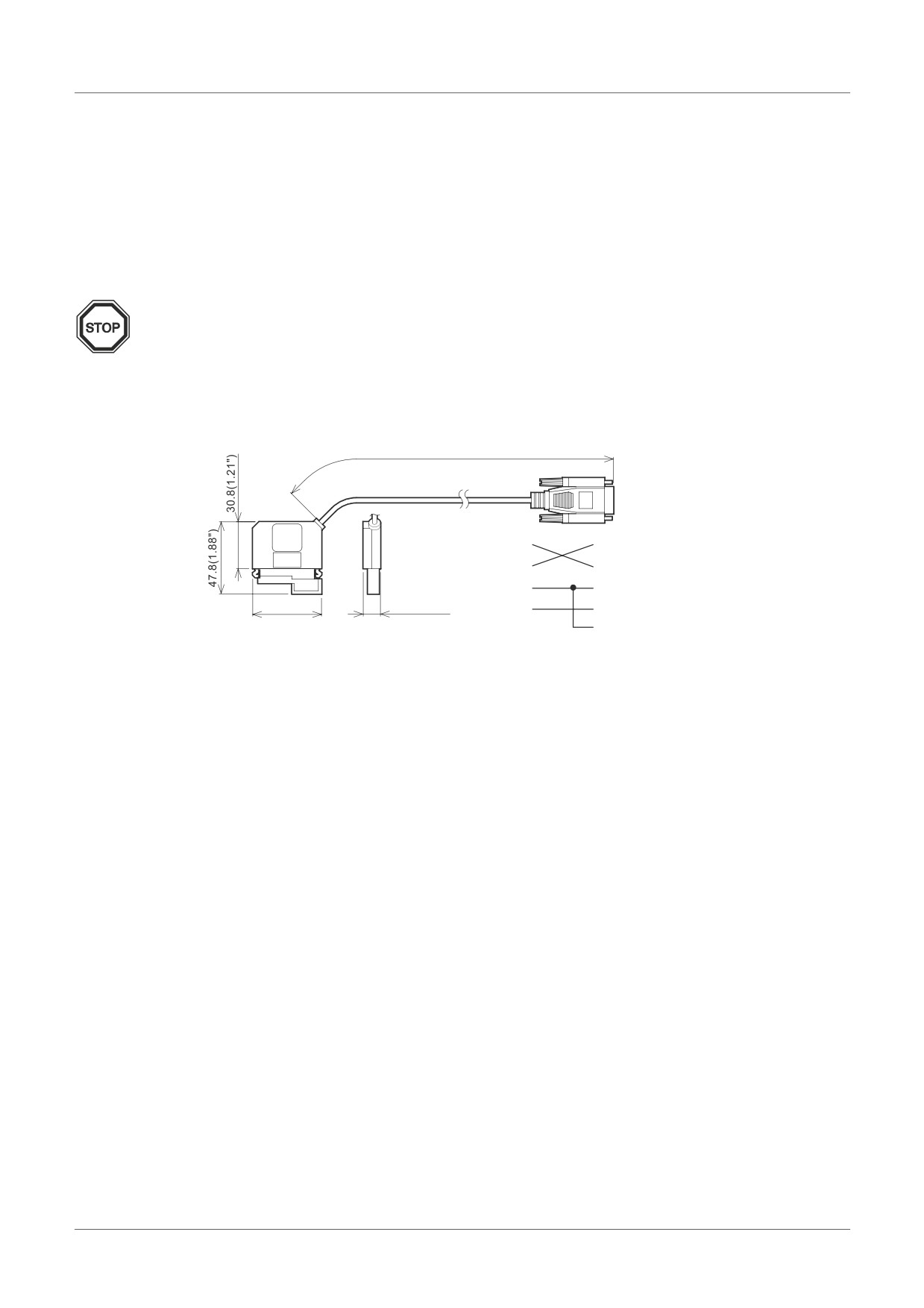
The AL-232CAB is an RS-232C cable used to connect an α series controller (α, α2) and a
personal computer that is running the programming software (AL-PCS/WIN-E).
Note;
• AL-232CAB cable cannot be used for any other applications.
• AL-232CAB cable rises about 40mm (1.57") above the top panel when connecting to an
α2 series controller.
7.1.1
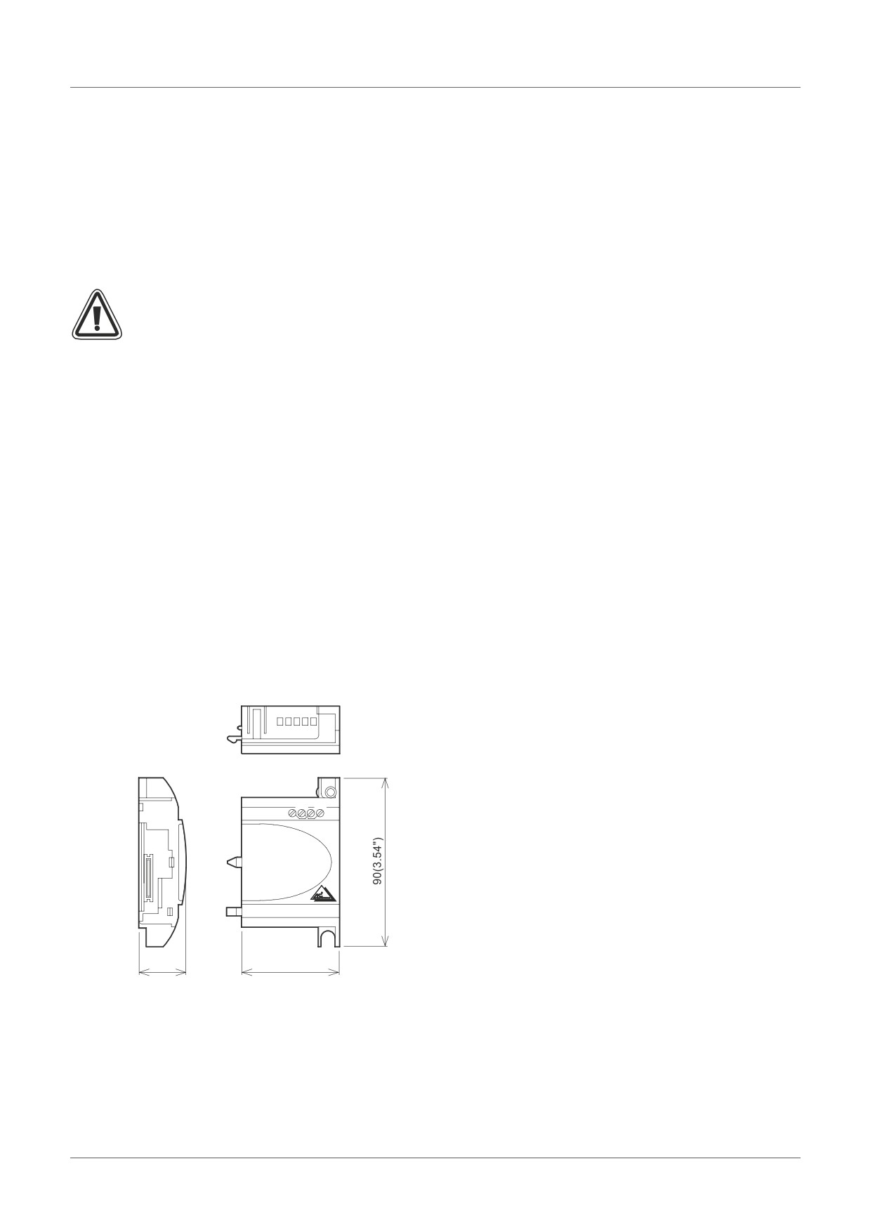
External Dimensions
Dimensions: mm (inches)
0
α2 series side
Personal computer side
(9-pin D-Sub female)
*1 Set this signal to
high-level.
ENG-32
AL-232CAB 7
7.2
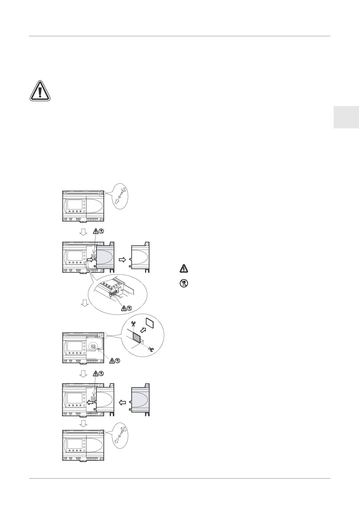
Connected to AL-232CAB cable
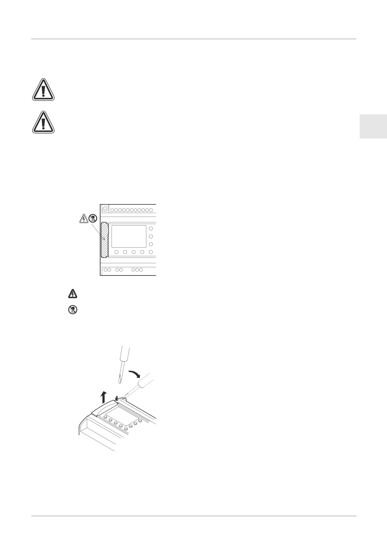
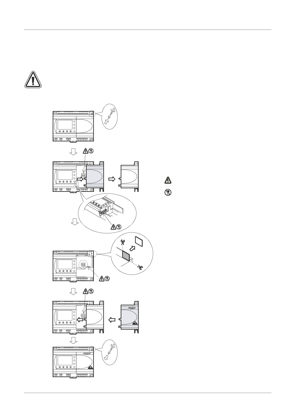
Remove cover and memory cassette
• Be careful of personal safety when removing the α2 cover.
Caution
• Turn off the power supply when you install or detach the AL-232CAB cable.
ENG
• Install the cover or the memory cassette after removing the AL-232CAB cable.
• When installing the connector cover or the memory cassette of α2 series, be careful not
to pinch your finger.
• Please hold the protective case when detaching the cable. DO NOT pull on the cord.
• DO NOT touch the following part when removing the cover, memory cassette or this
cable.
: A danger of electric shock.
: Do not touch the conductive parts of the product directly.
1) Removing the cover or the memory cassette
ENG-33
AL-232CAB 7
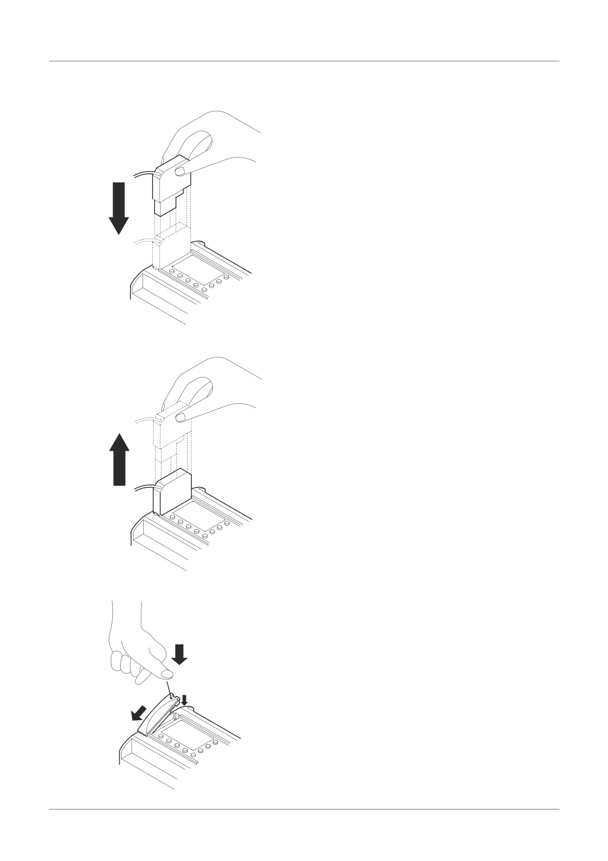
2) Connecting the AL-232CAB cable
3) Removing the AL-232CAB cable
4) Installing on the cover or the memory cassette
ENG-34
AL-232CAB 7
MEMO
ENG
ENG-35
AL2-GSM-CAB 8
8.
AL2-GSM-CAB
8.1
Introduction
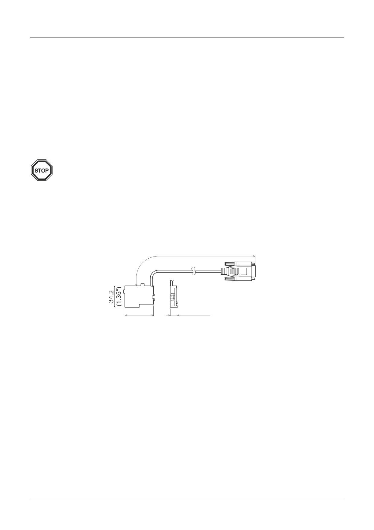
The AL2-GSM-CAB can be used to connect α2 Series Controllers to a normal or GSM
modem. The AL2-GSM-CAB can transfer Short Message Service (SMS) data to a GSM
modem for transmission to mobile phones and mail addresses or can facilitate remote
monitoring functions and program transfers via normal modems. RS-232C communication to a
personal computer can also be accomplished if an adaptor or cable is used.
Further information can be found in the α2 Programming Manual and α Software Manual.
Note;
• This cable cannot be used for any other applications.
• This cable attaches only to the α2 Series Controller (Model: AL2-14MR-*,AL2-24MR-*).
• Simultaneous communication through both ports of the α2 Series Controllers may result
in a damaged program or a malfunction in the controller.
8.1.1
External Dimensions
Figure 8.1: External Dimensions
Dimensions: mm (inches)
modem side
(9-pin D-Sub male)
α2 series side
ENG-36
AL2-GSM-CAB 8
8.1.2
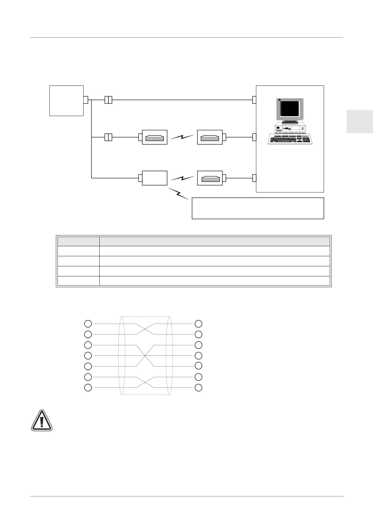
System Configuration with using AL2-GSM-CAB
Figure 8.2: System Configuration with AL2-GSM-CAB
Using Dedicated Protocol
AL2-14MR-*
c
d
AL2-24MR-*
Series
Remote Maintenance (Via Telephone Line)
ENG
Normal Modem
Normal Modem
c
e
f
Personal computer
Remote Maintenance, E-Mail (Via GSM)
- Programming Software
Normal Modem
(AL-PCS/WIN-E)
c
GSM
f
- Dedicated protocol
Modem
- E-Mail application
Sending SMS Message
Cellular Phone
(Supporting SMS message)
Table 8.1: System Configuration with AL2-GSM-CAB
Item
Using Cable
1
AL2-GSM-CAB
2
RS-232C cross cable (See Figure 8.3)
3
RS-232C straight cable for the modem (See Figure 8.5)
4
RS-232C straight cable for the modem (specified by modem manufacturer)
Figure 8.3: RS-232C Cross Cable Reference
(9-pin D-Sub female)
(9-pin D-Sub female)
2
2
3
3
4
4
5
5
6
6
7
7
8
8
Note;
The 4 and 7 signals must be set to high-level on the personal computer side.
If these signals are not set, it will not communicate to α2 series.
ENG-37
AL2-GSM-CAB 8
8.2
Installation
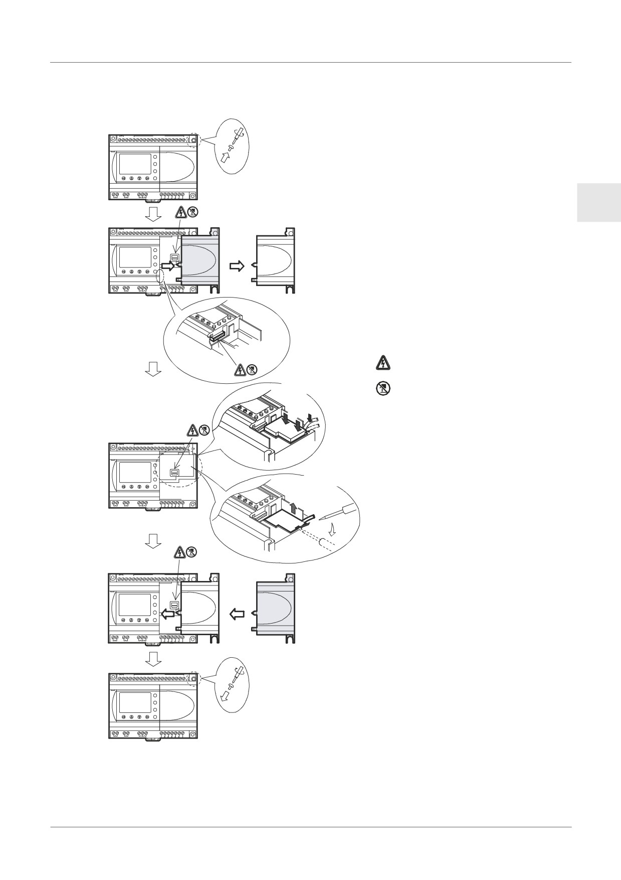
When installing AL2-GSM-CAB refer to Figure 8.4.
Caution
• Persons trained in the local and national electrical standards must install or remove the
AL2-GSM-CAB.
• Turn off the power supply when installing or removing the AL2-GSM-CAB.
• Put the cover back on after either installing or removing the AL2-GSM-CAB.
• Under no circumstances will Mitsubishi Electric be liable or responsible for any
consequential damage that may arise as a result of the installation or use of this
equipment.
• Do not pull on the cord, otherwise the cable may be damaged.
• When communicating to α2 series via GSM modem, the power supply for both units
must be turned ON at the same time. If they are not started up at same time, the α2
series will not communicate via GSM modem.
• Disconnect all terminals from the power supply before removing the cover.
ENG-38
AL2-GSM-CAB 8
Figure 8.4: Installation
1) Release screw ‘A’ and keep.
+
-
(A)
(B)
1
2
3
4
5
6
7
DC INPUT
8
9
10
11
12
13
14
15
1)
POWER
24V DC
2) Carefully remove the factory fitted
ESC
+
A
α2 expansion port cover or special
-
OK
module cover.
AL2-24MR-D
OUT1
OUT2
OUT3
OUT4
RELAY
OUTPUT
OUT
5
6
7
8
9
3) Install the AL2-GSM-CAB
into the
ENG
cavity, carefully placing the cable in
+
-
(A)
(B)
1
2
3
4
5
6
7
DC INPUT
8
9
10
11
12
13
14
15
the channel located on the input
2)
POWER
24V DC
terminal side.
ESC
+
-
4) Attach the α2 cover or expansion
OK
AL2-24MR-D
module taking care that there is no
RELAYOUTPUT
5
7
8
9
OUT1
OUT2
OUT3
OUT4
OUT
interference with the AL2-GSM-
CAB.
5) Tighten screw ‘A’ to a torque of 0.4
N·m.
: A danger of electric shock.
Install
: Do not touch the conductive parts
of the product directly.
d
c
+
-
(A)
(B)
1
2
3
4
5
6
7
DC INPUT
8
9
10
11
12
13
14
15
3)
POWER
24V DC
ESC
+
-
Remove
OK
AL2-24MR-D
e
OUT1
OUT2
OUT3
OUT4
RELAY
OUTPUT
OUT
5
6
7
8
9
c d
+
-
(A)
(B)
1
2
3
4
5
6
7
DC INPUT8
9
10
11
12
13
14
15
4)
POWER
24V DC
ESC
+
-
OK
AL2-24MR-D
RELAY
OUTPUT
5
6
7
8
9
OUT1
OUT2
OUT3
OUT4
OUT
+
-
(A)
(B)
1
2
3
4
5
6
7
DC INPUT
8
9
10
11
12
13
14
15
5)
POWER
24V DC
ESC
+
A
-
OK
AL2-24MR-D
OUT1
OUT2
OUT3
OUT4
RELAY
OUTPUT
OUT
5
6
7
8
9
ENG-39
AL2-GSM-CAB 8
8.3
Remote Maintenace with a Modem
Further information of the modem setup procedures can be found in the α2 Programming
Manual. The programming software (AL-PCS/WIN-E) provides the easiest method to setup
the modem.
8.3.1
Recommended Modems
The following modems have been successfully tested.
Table 8.2: Tested Modems
Maker name
Model name
Modem command (AT command)
3com
SP560V-P
ATE0Q1&B1&D0H0&I0&R1&S0S0=2S15=8&W
OMRON
ME3314
ATE0S0=2Q1&D0S15=8&R1&H0&W
AIWA
PV-AF3360
ATE0S0=2Q1&D0&M5\Q0\J0&W
Siemens
M20T
ATE0S0=2&S0;+IFC=0,0;+CMEE=1;+IPR=9600&W
8.3.2
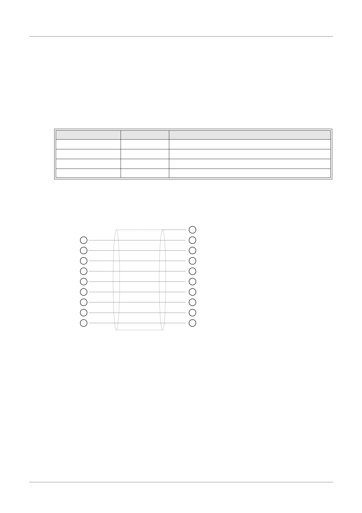
RS-232C Straight Cable Between Modem and AL2-GSM-CAB
Figure 8.5: RS-232C Straight Cable Reference Between a Modem and AL2-GSM-CAB
AL2-GSM-CAB Side
Modem Side
(9-pin D-Sub female)
(25-pin D-Sub male)
1
1
8
2
3
3
2
4
20
5
7
6
6
7
4
8
5
9
22
ENG-40
AL2-GSM-CAB 8
8.3.3
Modem Setting
1) Setting of personal computer side
Install the file for the setting of the attachment in the modem.
2) Setting of α2 series side
The modem on the α2 series side is set by the ModemInit command of the main unit.
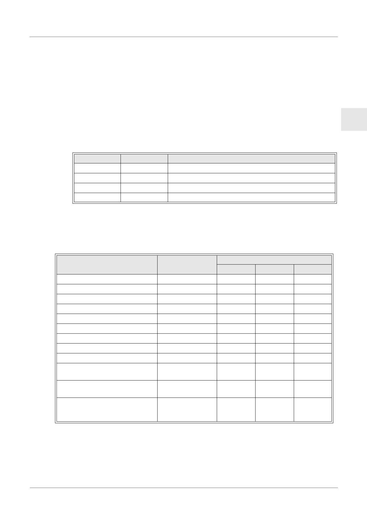
a) About the modem command (AT command)
ENG
Use the AT command to initialize the modem. Confirm details of the AT command in the
manual of the modem to be used. AT commands have been prepared for select modems
in the table 8.4 (normal modem) and 8.5 (GSM modem) below.
Table 8.3: Tested Modems
Maker name
Model name
Modem command (AT command)
3com
SP560V-P
ATE0Q1&B1&D0H0&I0&R1&S0S0=2S15=8&W
OMRON
ME3314
ATE0S0=2Q1&D0S15=8&R1&H0&W
AIWA
PV-AF3360
ATE0S0=2Q1&D0&M5\Q0\J0&W
Siemens
M20T
ATE0S0=2&S0;+IFC=0,0;+CMEE=1;+IPR=9600&W
Further information on the method to initialize a modem can be found in the α2
Programming Manual.
When modems not listed in the table above are used, set the AT command to meet the
following requirements.
Table 8.4: AT Command for Modem (Normal Modem)
Example Setting
Setting Item
Set content
SP560V-P
ME3314
PV-AF3360
Setting of command echo
None
E0
E0
E0
Call frequency of auto-answering
Twice
S0=2
S0=2
S0=2
Displayed result code
None
Q1
Q1
Q1
DTR control
Always on
&D0
&D0
&D0
DSR control
Always on
&S0
Communicate mode
V.42bis mode
S15=8
S15=8
&M5
Speed of terminal fixed dimension
Fixed
&B1
\J0
Terminal flow control scheme
None
-&R1
\Q0
Flow control of transmission data
None
&H0
&H0
-
Flow control of received data
None
&I0
(software)
Flow control of received data
None
&R1
(RTS control)
Write in the
Writing in nonvolatile memory
nonvolatile
&W
&W
&W
memory.
ENG-41
AL2-GSM-CAB 8
Table 8.5: AT Command for GSM Modem
Example Setting
Setting Item
Set content
M20T
Enable command echo
Echo mode OFF
E0
Set number of ring before
Enable automatic answering on the ring
S0=2
automatically answering the call
twice
Set circuit data set ready (DSR)
DSR always ON
&S0
function mode
• Specifies the method which will be used
by TE when data is received from TA:
None
Set TE-TA local data flow control
+IFC=0,0
• Specifies the method which will be used
by TA when data is received from TE:
None
Report mobile equipment error
Enable result code and use numeric value
+CMEE=1
Set fixed local rate
Baud Rate: 9600 bps
+IPR=9600
Set circuit data carrier detect
DCD line is ON only in the presence of
&C1
(DCD) function mode*1
Data Carrier
9600 bps (V.32), asynchronous modem,
Select bearer service type*1
+CBST=7,0,1
non-transparent
Store current parameter to use
The user profile is stored in non-volatile
&W
defined profile
memory
*1 In Siemens M20T case, these settings are not necessary because they are default
settings. If using other GSM Modem, maybe these settings are necessary.
b) Timing to initialize the modem during system startup
In the α2 series, there is a function to delay the transmission of the modem command (AT
command) to initialize the modem from the main unit at start up. The delay can range from
0 - 10 seconds. This command can be useful to ensure the AT command is correctly
transmitted when the α2 series start up is faster than the modem start up.
Further information for the modem operation can be found in the α2 Programming Manual
and the α Software Manual.
ENG-42
AL2-GSM-CAB 8
MEMO
ENG
ENG-43
AL2-ASI-BD (AL2-14MR-*, AL2-24MR-* ) 9
9.
AL2-ASI-BD (AL2-14MR-*, AL2-24MR-* )
The AL2-ASI-BD Actuator Sensor Interface board module is used in conjunction with α2
series controller for data communication over an Actuator Sensor Interface (AS-interface)
network.
Further information can be found in the α2 Series Programming Manuals.
Caution
• Persons trained in the local and national electrical standards must replace the
AL2-ASI-BD.
• Turn off the power supply when you install or remove the AL2-ASI-BD.
• Replace the cover after removing the AL2-ASI-BD.
• Under no circumstances will Mitsubishi Electric be liable or responsible for any
consequential damage that may arise as a result of the installation or use of this
equipment.
9.1
Introduction
The AL2-ASI-BD connects onto the main unit of the α2 series controller, forming a slave
station for an AS-interface network (Input 4 points, Output 4 points). A maximum of 31 slaves
can be connected to form an AS-interface network. Power for the communication is supplied
over the AS-interface bus by the AS-interface power supply. The communication signal is
superimposed over the power supply on the AS-interface bus.
9.1.1
External Dimensions
Figure 9.1: External Dimensions
Unit: mm (inches)
ENG-44
AL2-ASI-BD (AL2-14MR-*, AL2-24MR-* ) 9
9.1.2
System Configuration
Figure 9.2: System Configuration
AS-interface Master
AS-interface Slave
Module
(Sensor / Actuator)
ENG
AS-interface Slave
AS-interface
AS-interface Slave
AS-interface Slave
(α2 Series
Power Supply
(Sensor / Actuator)
(Sensor / Actuator)
+ AL2-ASI-BD)
9.2
Specifications
For general specifications please refer to the Chapter 2.
Table 9.1: Hardware Communication Specifications
Item
Content
Number of I/O
4 Input (E01-E04) 4 Output (A01-A04)
I/O Refresh Time
Max. 5ms
Network Distance
Max. 100m
External Power Voltage
Typ. 30.5V DC (AS-interface Power supply)
External Power Current Consumption
40 mA or less
EC Directive
EMC
Complies with
AS-interface Certification
Table 9.2: Software Communication Specifications
Item
Content
Station Number
Set by Master Station (Factory default 0)
IO Code
7
ID Code
F
Data Bit
D0 - D3
Input/Output 01 - 04 (E01 - E04, A01 - A04)
P0
Communication monitor (set by default).*1
Parameter Bit
P1,P2,P3
Unused
M6
“ON” when communication Error of AS-interface occurs
System Bit
M7
“ON” when communication Error by AS-interface power fail occurs
ON: Connect to AS-interface network
Control Bit
N1
OFF: Unconnected to AS-interface network
*1 Function to reset input signal (E01 - E04) when AS-interface communication is cut for 70
ms or more.
ENG-45
AL2-ASI-BD (AL2-14MR-*, AL2-24MR-* ) 9
9.3
Wiring & Installation
9.3.1
Installation
Caution
Disconnect all terminals from the power supply before removing the cover.
Figure 9.3: Installation
1) Release screw ‘A’ and keep.
+
-
(A)
(B)
1
2
3
4
5
6
7
DC INPUT
8
9
10
11
12
13
14
15
1)
POWER24V DC
2) Carefully remove the factory fitted
ESC
+
A
expansion port cover.
-
OK
AL2-24MR-D
RELAY
3) Cut away section ‘B’ from the α2 series
OUTPUT
5
6
7
8
9
OUT1
OUT2
OUT3
OUT4
OUT
controller main unit.
4) Attach the expansion module to the main
unit.
+
-
(A)
(B)
1
2
3
4
5
6
7
DC INPUT
8
9
10
11
12
13
14
15
2)
POWER
24V DC
ESC
5) Tighten screw ‘A’ to a torque of 0.4 N·m.
+
-
OK
: A danger of electric shock.
AL2-24MR-D
RELAYOUTPUT
5
7
8
9
OUT1
OUT2
OUT3
OUT4
OUT
: Do not touch the conductive parts of the
product directly.
B
+
-
(A)
(B)
1
2
3
4
5
6
7
DC INPUT
8
9
10
11
12
13
14
15
3)
POWER24V DC
ESC
+
-
OK
AL2-24MR-D
RELAY
OUT1
OUT2
OUT3
OUT4
OUTPUT
OUT
5
6
7
8
9
+
-
(A)
(B)
1
2
3
4
5
6
7
DC INPUT
8
9
10
11
12
13
14
15
4)
ASI+
ASI-ASI+
ASI-
24V DC
POWER
ESC
+
-
OK
AL2-24MR-D
RELAY
OUTPUT
5
6
7
8
9
OUT1
OUT2
OUT3
OUT4
OUT
+
-
(A)
(B)
1
2
3
4
5
6
7
DC INPUT
8
9
10
11
12
13
14
15
ASI+
ASI-ASI+
ASI-
5)
POWER
24V DC
ESC
+
A
-
OK
AL2-24MR-D
RELAYOUTPUT
5
6
7
8
9
OUT1
OUT2
OUT3
OUT4
OUT
ENG-46
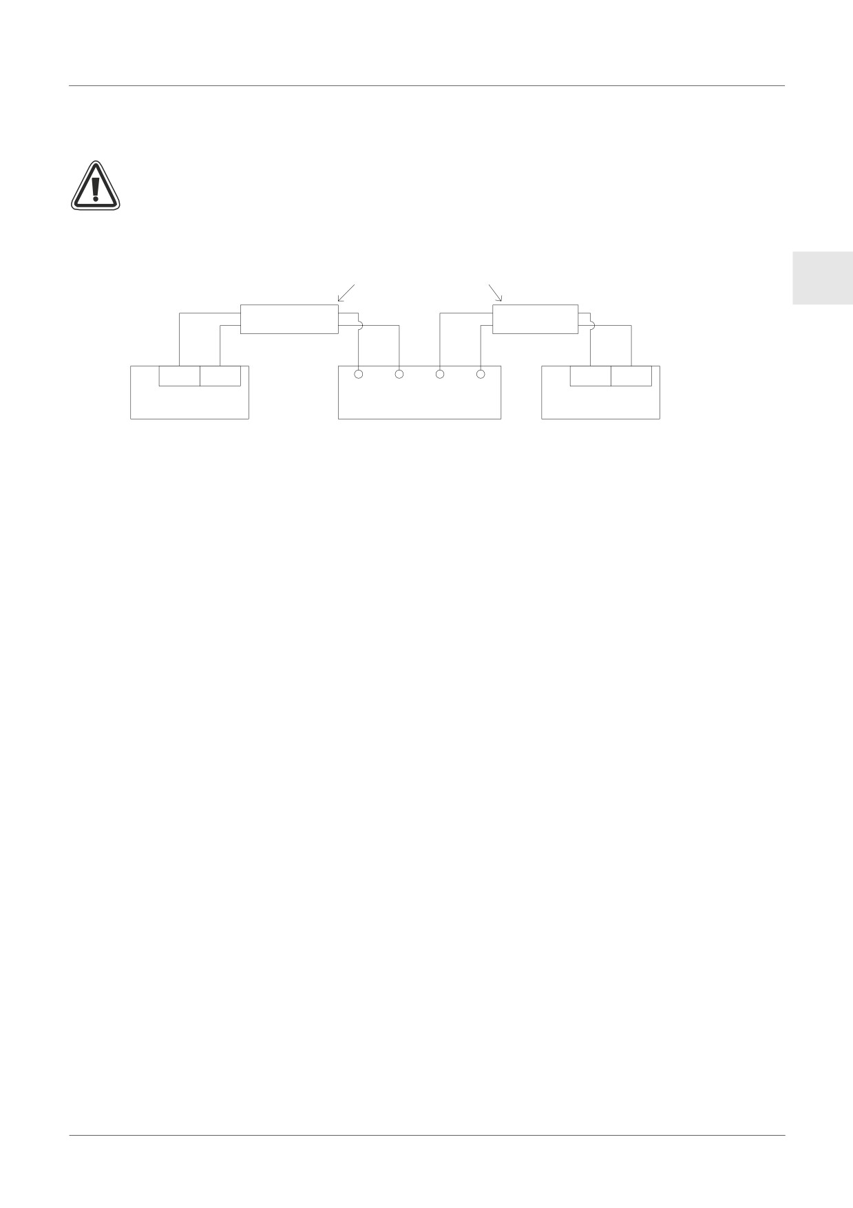
AL2-ASI-BD (AL2-14MR-*, AL2-24MR-* ) 9
9.3.2
Wiring
Use the AS-interface flat cable (yellow) for connecting the AL2-ASI-BD to the network.
When connecting AS-interface cable to the module, tighten communication connector pin
screws to a torque of 0.5 - 0.6N·m.
Figure 9.4: Wiring
AS-interface Flat cable (Yellow)
ENG
ASI+
ASI-
ASI+
ASI-
ASI+ ASI- ASI+ ASI-
AS-interface Master
AS-interface Power
Module
AL2-ASI-BD
Supply
9.4
Slave Address Setting & Diagnostics
9.4.1
Setting Slave Address
The address of AL2-ASI-BD must be set from the AS-interface master module. The setting
range of the slave address is 1 to 31. New modules are preset to 0 before shipping, if a module
has been previously assigned an address other than 0, it must be reset to 0 before it need to
add into new AS-interface network.
Refer to the AS-interface master module's manual for details of how to set station address
from the AS-interface master.
Many modules can be added to a network at one time, all but one of them should be set in their
passive state (set N1=1). Once the network has been powered up the modules can be
individually activated (set N1=0), where the Master station will assign a slave address.
9.4.2
Applicable Error checks
1) If a Communication error (M6) occurs;
- Check connections to the AS-interface master, and that the slave station number is
correct.
2) If a Communications power supply error (M7) occurs;
- Check the connection of the AS-interface Bus cable at each affected unit, also the AS-
interface power supply and its operation.
ENG-47
DCF77 Radio Clock 10
10.
DCF77 Radio Clock
The DCF77 function for the α2 series provides automatic setup of the RTC (Real Time Clock)
from receiving and decoding DCF77 time information that is broadcast over the radio signal
77.5kHz from Frankfurt/Germany.
DCF77
Deutschland
Radio band C (long wave)
Frankfurt
77.5kHz
10.1
Introduction
Table 10.1: Radio Clock
Item
Content
Transmitter location
Mainflingen, 25km south of Frankfurt/Germany
Frequency
77.5kHz
Transmission Range
2000km
Coding
BCD (Binary Coded Decimal)
Transmitted Data
minutes, hours, calendar day, day of the week, month, year
Transmission Time
24 hours daily
The carrier amplitude is reduced to 25% at the beginning of each second for a period of 100ms
(binary:0) or 200ms (binary:1), except for the 59th second.
ENG-48
DCF77 Radio Clock 10
10.2
System Configuration
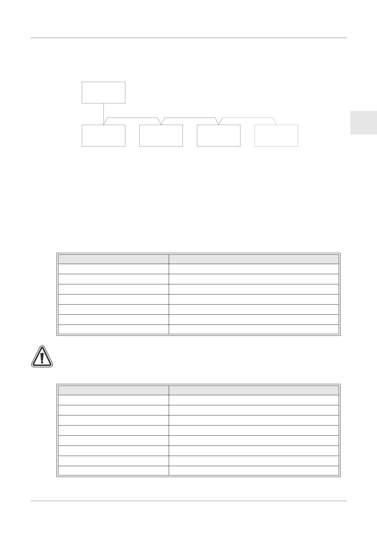
Figure 10.1:
DCF 77
Antenna*
ENG
NT DCF 77
α2 Series
α2 Series
α2 Series
Power-pack*
* Manufactured by Theben AG
The α2 series must use a Theben DCF77 antenna and at least one Theben device to power
the antenna. The α2 series internal decoding will only recognise a Theben DCF77 signal.
The extra Theben device must power the antenna with 12V DC, only a Theben power supply
can be used to provide the required power and signal line.
A maximum of 10 α2 series main units can be connected in one configuration.
10.3
Specifications
For general specifications please refer to Chapter 2.
Table 10.2: Theben DCF77 Antenna
Item
Content
Part Name
DCF 77 Antenna 907 0 243
Ambient Temperature
-20 - 70°C
Protection
IP 54
Reception Threshold
100µV/m
Reception Area
approx. 1000km from Frankfurt
Connection cable length
max. 200m
Polarity
none
Caution
• To avoid interference from external signals, do not use the Theben DCF77 antenna in
TV, PC or telecommunications areas.
Table 10.3: Theben Power-pack
Item
Content
Part Name
Power pack NT DCF 77 907 0 182
Operating Voltage
230V AC~ +/-10%
Nominal frequency
50-60Hz
Internal consumption
max. 3VA
Power-line length
max. 200m individually conducted two-core power line
Capacity
10 units
Protection class
II acc. to EN 60335
Protection
IP20 acc. to EN 60529
ENG-49
DCF77 Radio Clock 10
Table 10.4: Applicable Version
PLC Type
Applicable version
α2 Series (DC Version only)
V2.00 or later
VLS Software
V2.30 or later
Caution
• The AC version of the α2 series cannot be used to receive DCF77 radio signals.
• Only analog inputs that are available with the DC version of the a2 series can be used to
decode DCF77 radio signals.
Table 10.5: Software Specifications
Item
Content
M10
“ON” during DCF77 decoding
System Bit
M11
Pulses “ON” when DCF77 finishes decoding without an error
M15
“ON” when DCF77 finishes decoding an error
For further Front programming details please refer to the α2 Programming Manual
(JY992D97101).
10.4
Wiring
10.4.1
Wiring
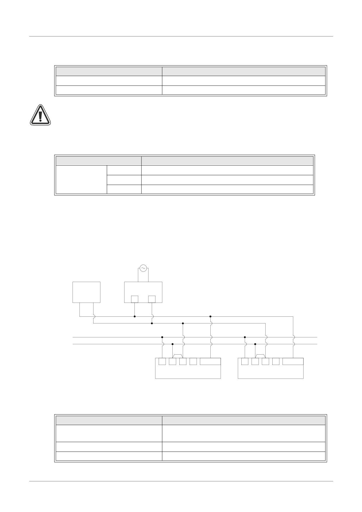
Figure 10.2: Wiring
NT DCF 77
DCF 77
Power-pack*
Antenna*
+
-
24V+
24V-
+
-
A
B
I01-I08
+
-
A
B
I01-I08
α2
α2
* Manufactured by Theben AG
The α2 series controller must be wired for a source configuration, otherwise, the DCF77 signal
will not be received and decoded at the analog inputs.
Table 10.6: Wiring conditions
Item
Description
AL2-10MR-D:I01 - I06
α2 Series Antenna signal inputs
AL2-14MR-D,AL2-24MR-D:I01 - I08
Max. α2 Series controllers
10 units
Max. wiring distance from antenna
200m
ENG-50
DCF77 Radio Clock 10
10.4.2
DCF77 Setup from α2 display
1) From the TopMenu, scroll to “ClockSet” and press the “OK” key. From the options that
appear, scroll to “Radioclock” and press the “OK” key. Only one option appears if the
Radioclock has not been activated. Scroll to “Radioclock” and press the “OK” key.
Radi oCl ock
Radi oCl ock
ENG
2) From the options that appear, scroll to “DCF77” and press the “OK” key.
Radi oCl ock
Not Use
DCF 7 7
3) Choose the α2 Analog Input (I01-I08) that carries the DCF77 antenna signal. More options
will appear under the Radioclock menu. Scroll to “ Input” and press the “OK” key.*1
Rad i oCl ock
Rad i oCl ock
I npu t
T imeDi f f e r
4) Enter the Analog Input (I01-I08) with the +, - buttons and press the “OK” key.
Radi oCl ock
Input
I01
5) Adjust for the timezone difference between Frankfurt Germany and the controllers’ location.
This amount is added to the received time. Scroll to “TimeDiffer” and press the “OK” key.
Rad i oCl ock
Rad i oCl ock
I npu t
T imeDi f f e r
6) Select the timezone difference in half hour increments using the +,- buttons. Press “OK” to
select the current timezone difference.
Rad i oCl ock
T imeDi f f e r
0 .0
h r s
7) The time signal decoding can be manually stopped or started. Scroll to “Manual” and press
the “OK” key.
Rad i oCl ock
I npu t
T imeDi f f e r
Ma n u a l
ENG-51
DCF77 Radio Clock 10
8) Press the “OK” or “ESC” keys to preform an execute or cancel operation.
Manua l
St op Ac t
OK o r ESC
Note
*1 The α2 Controller will alternate between “No signal” and “Radioclock” if the DCF77
signal is not received and decoded.
10.4.3
Automatically Start
The DCF77 Radioclock decoding phase will start automatically if the following conditions are
satisfied:
1) The α2 Real Time Clock (RTC) reaches 1.00am.
2) The α2 Real Time Clock (RTC) will produce an error after Powering ON the controller.
10.4.4
Automatically Stop
The DCF77 Radioclock decoding phase will stop automatically if the following conditions are
satisfied:
1) The α2 Real Time Clock (RTC) was configured correctly and a valid time was received
2) No valid time was received during 30 minutes of retries.
10.4.5
Verification of Received Time
The DCF77 Radioclock decoded time is checked for validity based on the following three
items:
1) Parity Check - The DCF77 time code data frame is protected by 3 (even) parity bits. The
first parity bit protects the minute data, the second protects the hour data and the third parity
bit protects the day, day of the week, month and year data.
2) Data Range Check -
a) 0< mintues<59
b) 0< hours<23
c) 1< days<31
d) 1< month<12
e) 0< year<59
3) Time Difference Check - The difference between two received time frames must equate to 1
minute, thus, the total time (in minutes from 1990/01/01) of every time frame is referenced.
Caution
• When "Start Act." is used to manually start DCF77 decoding, the user must check
the state of M10 (decoding active flag) 30 minutes after starting the decoding. If
M10 is off, DCF77 decoding finished without error. If M10 is still ON, there is a
problem with either the wiring or the availability of the signal in the location of
use. The user should check both possible causes.
ENG-52
DCF77 Radio Clock 10
MEMO
ENG
ENG-53
AL2-2DA (AL2-14MR-*, AL2-24MR-*) 11
11.
AL2-2DA (AL2-14MR-*, AL2-24MR-*)
The AL2-2DA Analog Output module should be used with the α2 Series Controller for 2
channels of either voltage or current output.
Further information can be found in the α2 Series Programming Manual and the AL2-2DA
Installation Manual.
Caution
• Persons trained in the local and national electrical standards must perform all tasks
associated with wiring the α2 Series Controller.
• The α2 Series is not designed to be used in life critical or fail safe applications.
• Under no circumstances will Mitsubishi Electric be liable or responsible for any
consequential damage that may arise as a result of the installation or use of this
equipment.
• Securely install the AL2-2DA to the α2 Series controller to avoid any malfunction.
EMC Caution
Mitsubishi Electric α2 Series Analog module has been found to be compliant to the said
European standards and directive. However, (for the very best performance from what are in
fact delicate measuring and controller output devices) Mitsubishi Electric would like to make
the following points:
•
As analog modules are sensitive by nature, their use should be considered carefully. For
users of proprietary cables (integral with sensors or actuators), these users should follow
those manufacturers installation requirements.
•
Mitsubishi Electric recommends that shielded cables should be used. If NO other EMC
protection is provided, then users may experience temporary errors not exceeding
+10%/-10% in very heavy industrial areas. However, Mitsubishi Electric suggest that if
adequate EMC precautions are followed with general good EMC practise for the users
complete control system, users should expect normal errors as specified in each
independent product manual.
•
Make sure to attach a noise filter to the power cable.
Mitsubishi's EMC tests have been carried out on a noise filter with the common mode
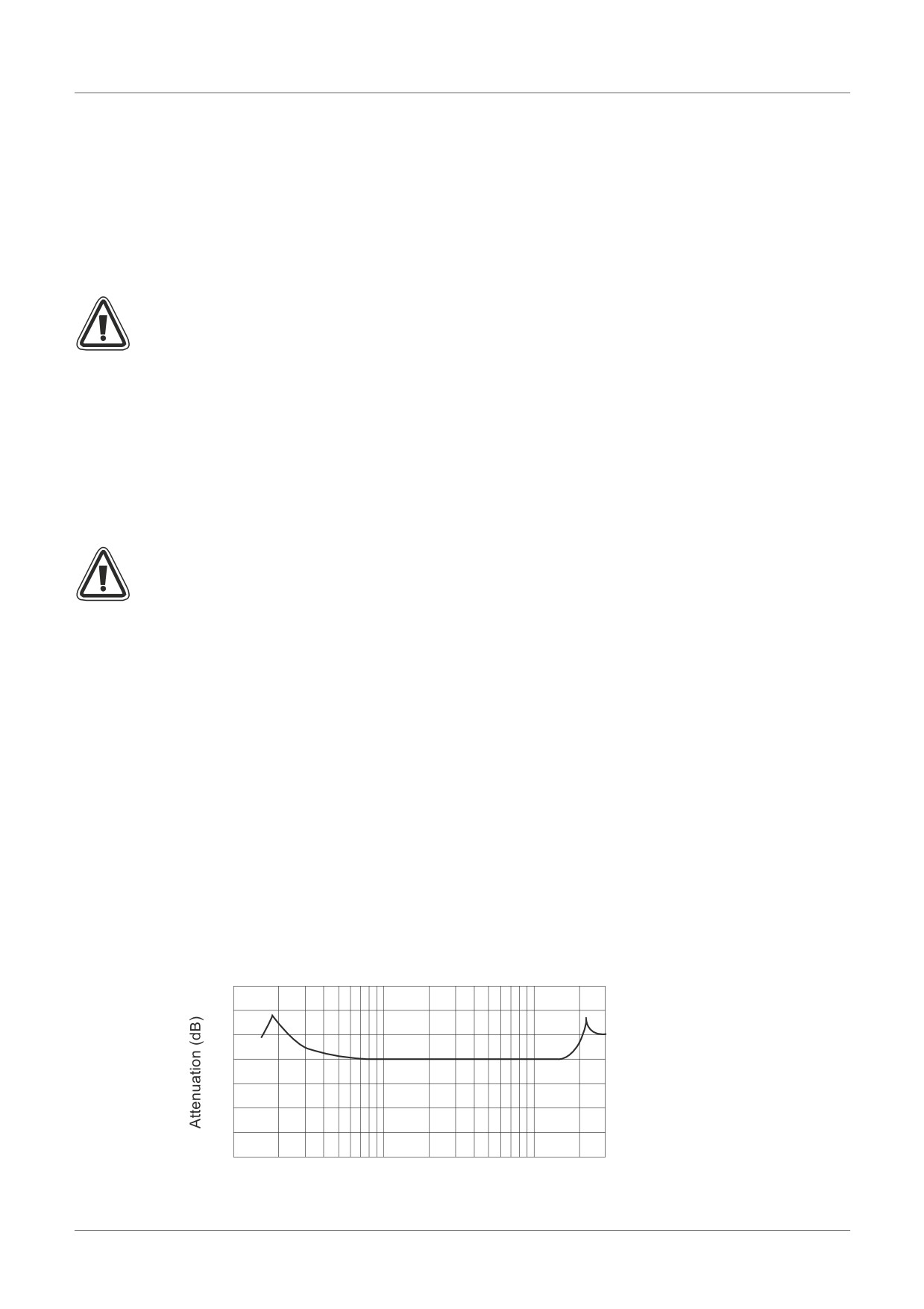
damping characteristics (Figure 11.1) of the 50 dB mean at 150 kHz to 2 MHz.
Figure 11.1: Damping Characteristics of Noise Filter
60
40
20
0
0.15
1
10
30
Frequency (MHz)
ENG-54
AL2-2DA (AL2-14MR-*, AL2-24MR-*) 11
11.1
Introduction
The AL2-2DA Analog Output Module (hereafter called "AL2-2DA") is to be installed onto an α2
Series Controller and should be used to convert a digital value to a voltage (0-10V) or current
(4-20mA) analog output signal.
The AL2-2DA is to be used in conjunction with the α2 Series Controller's Analog Output (AO)
function block. Refer to the α2 Programming manuals for further details.
ENG
11.1.1
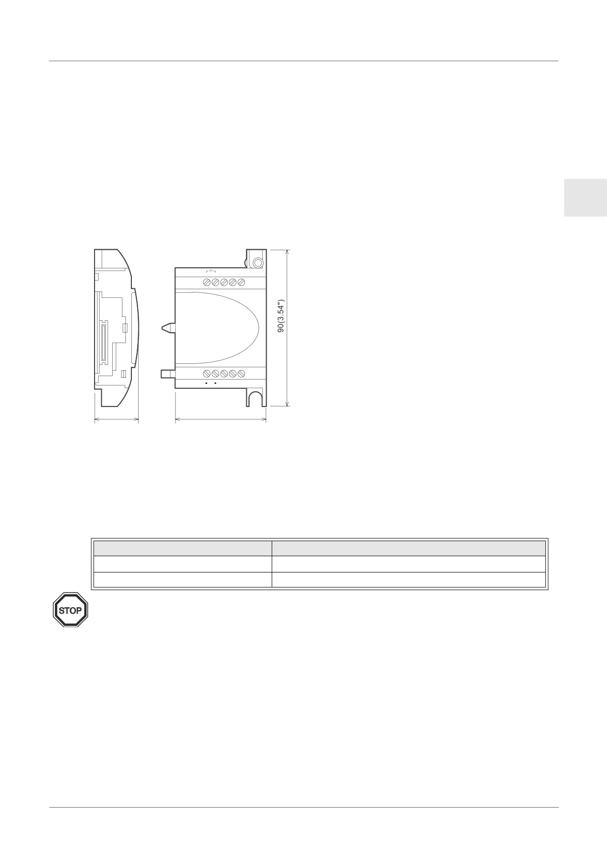
External Dimensions
Figure 11.2:External Dimensions
Unit:mm (inches)
11.1.2
System Configuration
For general specifications please refer to Chapter 2.
Table 11.1: Applicable Version
PLC Type
Applicable version
AL2-14MR-*,AL2-24MR-*
V2.00 or later
VLS Software
V2.30 or later
Note
1) The AL2-2DA cannot be used together with either an AL2-4EX-A2, AL2-4EX, AL2-ASI-BD,
AL2-4EYR or AL2-4EYT.
2) The AL2-2DA cannot be used with the original α Series Controllers.
ENG-55
AL2-2DA (AL2-14MR-*, AL2-24MR-*) 11
11.2
Specification
Table 11.2: Power Specification
Item
Content
Integrated Power Supply
Supplied from the α2 Main Unit
External Supply for Analog Output
24V DC +20%, -15%
Maximum Power Consumption
1.5W
Fuse <Rating>/<Type>
86 V DC 1.6A / Inrush-withstand
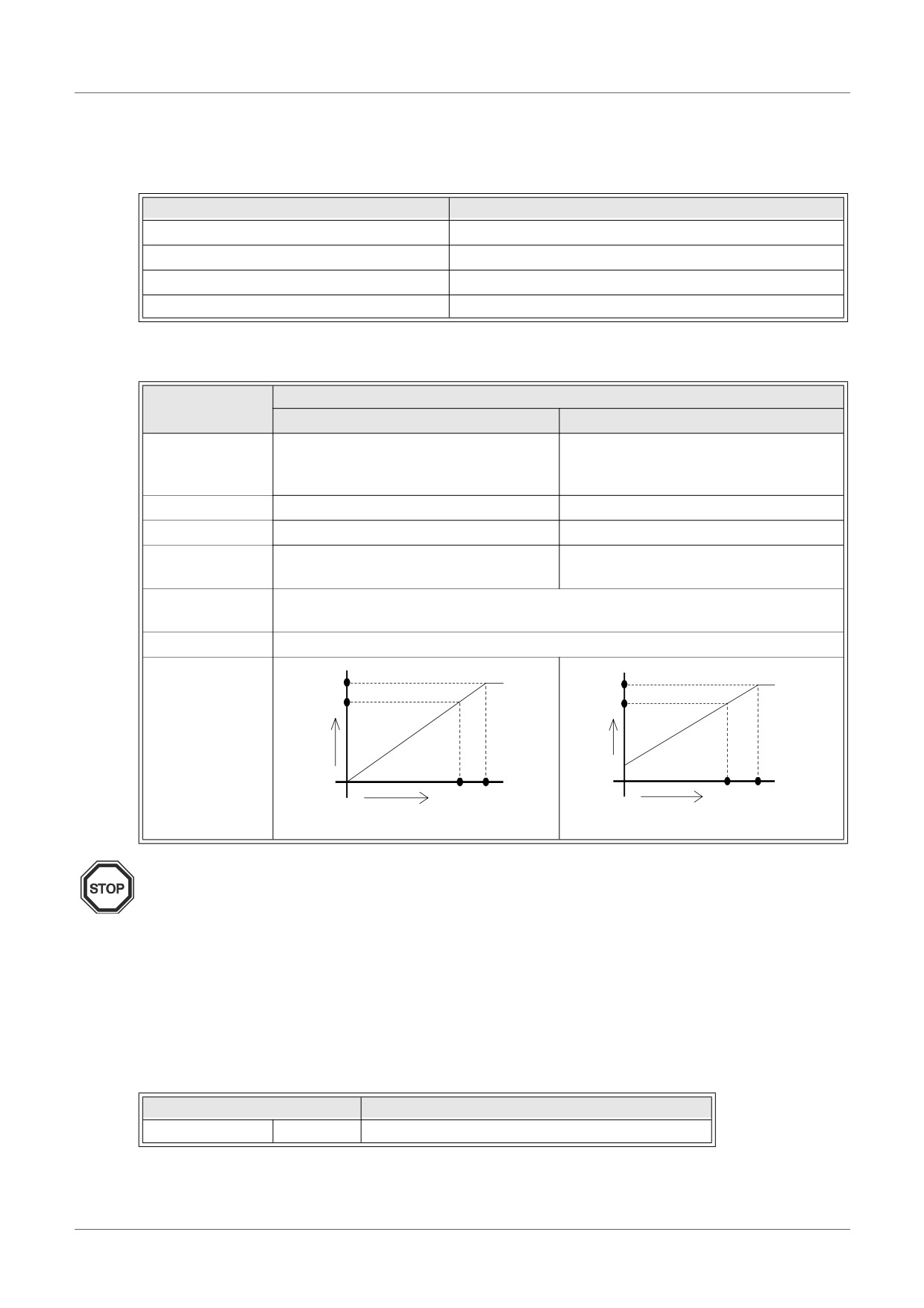
Table 11.3: Hardware Specification
Item
Specification
Voltage
Current
4 - 20mA
Analog Output
0 - 10V DC
(External load resistance less than
Range
(External load resistance 5k - 1MΩ)
500Ω)
Digital Input
0 to 4000
0 to 2000
Resolution
2.5mV (10V / 4000)
8µA ((20-4)mA / 2000)
Integrated
+/- 1% Full scale (0-10V : +/-0.1V)
+/- 1% Full scale (4-20mA : +/-0.16mA)
accuracy
D/A Conversion
20ms (10ms x 2ch)
Time
Isolation Circuit
Photocoupler
10.1V
20.16mA
10V
20mA
Analog
Analog
Input
output
output
Characteristics
4mA
0
4000 4040
0
2000 2020
Digital input
Digital input
Note
1) When the external load resistance is 5kΩ to 1MΩ, the overall accuracy of the voltage
output is adjusted to “+/-1%”.(Factory calibration point is 10kΩ external load)
If the load resistance is smaller than 5kΩ, the output voltage becomes smaller than the
correct value.
2) If the current output mode is used, an external load resistance of 500Ω or less must be
used.
If the load resistance exceeds 500Ω, the output current will be lower than the correct
value.
Table 11.4: Software Specification
Item
Content
System Bit
M16
“ON” when external power for the AL2-2DA
ENG-56
AL2-2DA (AL2-14MR-*, AL2-24MR-*) 11
11.3
Wiring & Installation
11.3.1
Installation
Caution
• Disconnect all terminals from the power supply before installing the AL2-2DA.
• Do not install in areas with: excessive or conductive dust, corrosive or flammable gas,
moisture or rain, excessive heat, regular impact shocks or excessive vibration.
ENG
• The α2 Series Controller and AL2-2DA must be installed in a distribution box or a control
cabinet.
• Leave a minimum of 10 mm (0.40") of space for ventilation between the top and bottom
edges of the α2 Series Controller and the enclosure walls.
Figure 11.3: Installation
+
-
(A)
(B)
1
2
3
4
5
6
7
DC INPUT
8
9
10
11
12
13
14
15
1) Release screw ‘A’ and keep.
1)
24V DC
POWER
ESC
2) Carefully remove the factory fitted expansion
+
A
-
OK
port cover.
AL2-24MR-D
OUT1
OUT2
OUT3
OUT4
RELAYOUTPUT
OUT
5
6
7
8
9
3) Cut away section
‘B’ from the α2 series
controller main unit.
+
-
(A)
(B)
1
2
3
4
5
6
7
DC INPUT
8
9
10
11
12
13
14
15
4) Attach the expansion module to the main unit.
2)
POWER
24V DC
ESC
+
5) Tighten screw ‘A’ to a torque of 0.4 N·m.
-
OK
AL2-24MR-D
RELAYOUTPUT
5
7
8
9
OUT1
OUT2
OUT3
OUT4
OUT
: A danger of electric shock.
: Do not touch the conductive parts of the
product directly.
B
+
-
(A)
(B)
1
2
3
4
5
6
7
DC INPUT
8
9
10
11
12
13
14
15
3)
POWER
24V DC
ESC
+
-
OK
AL2-24MR-D
OUT1
OUT2
OUT3
OUT4
RELAYOUTPUT
OUT
5
6
7
8
9
+
-
(A)
(B)
1
2
3
4
5
6
7
DC INPUT
8
9
10
11
12
13
14
15
4)
POWER
24V DC
ESC
+
-
OK
AL2-24MR-D
OUT1
OUT2
OUT3
OUT4
RELAY
OUTPUT
OUT
5
6
7
8
9
+
-
(A)
(B)
1
2
3
4
5
6
7
DC INPUT8
9
10
11
12
13
14
15
5)
24V DC
POWER
ESC
+
A
-
OK
AL2-24MR-D
RELAYOUTPUT
5
6
7
8
9
OUT1
OUT2
OUT3
OUT4
OUT
ENG-57
AL2-2DA (AL2-14MR-*, AL2-24MR-*) 11
11.3.2
Wiring
Caution
• Turn off the Power before performing any wiring operations.
• The Output cables should not be run through the same multi core cable or share the
same wire.
• The wire should be used as a single cable or the multi core wires (can be used with a
crimp terminal) should be carefully twisted together.
Do not connect a soldered wire end to the α2 Series Controller.
• The Output cable length must be less than 30 m (98' 5")
• To avoid damaging the wire, tighten to a torque of 0.5 - 0.6 N·m.
• The connectors must be covered to prevent contact with “Live” wires.
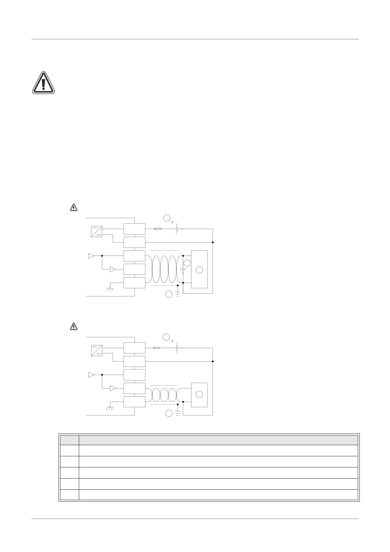
Figure 11.4:Wiring in Voltage output mode
Note: "+" and "-" terminals are nonreversible.
4
DC/DC converter
24V DC
1.0A
+
-
VO+
2
IO+
3
VIO-
AL2-2DA
1
Figure 11.5:Wiring in Current output mode
Note: "+" and "-" terminals are nonreversible.
4
24V DC
DC/DC converter
1.0A
+
-
VO+
IO+
5
VIO-
AL2-2DA
1
Table 11.5: Wiring Notation
Item
Description
1
Grounding resistance of 100Ω or less
2
In the case of apparent excess noise please connect a 0.1-0.47µF capacitor
3
External equipment such as an Inverter, etc.
4
External 24VDC power supply
5
External equipment such as a Record meter, etc.
ENG-58
AL2-2DA (AL2-14MR-*, AL2-24MR-*) 11
11.3.3
Applicable Error checks
1) If an External power supply error (M16) occurs:
Check the “+” and “-” connections to the AL2-2DA for correct wiring and installation
procedures.
Check the original Power Supply source for 24V DC operation.
ENG
ENG-59
AL2-2PT-ADP 12
12.
AL2-2PT-ADP
The AL2-2PT-ADP PT100 adaptor module (hereafter called “AL2-2PT-ADP”) should be used
to amplify PT100 temperature input to 0 - 10V voltage analog signal for use in the main unit.
Further information can be found in the AL2-2PT-ADP Installation Manual.
Caution
• Persons trained in the local and national electrical standards must perform all tasks
associated with wiring the α2 Series Controller and AL2-2PT-ADP.
• The α2 Series is not designed to be used in life critical or fail safe applications.
• Under no circumstances will Mitsubishi Electric be liable or responsible for any
consequential damage that may arise as a result of the installation or use of this
equipment.
EMC Caution
Mitsubishi Electric α2 Series Analog modules has been found to be compliant to the said
European standards and directive. However, (for the very best performance from what are in
fact delicate measuring and controller output devices) Mitsubishi Electric would like to make
the following points:
• As analog modules are sensitive by nature, their use should be considered carefully. For
users of proprietary cables (integral with sensors or actuators), these users should follow
those manufacturers installation requirements.
• Mitsubishi Electric recommends that shielded cables should be used. If NO other EMC
protection is provided, then users may experience temporary errors not exceeding
+10%/-10% in very heavy industrial areas. However, Mitsubishi Electric suggest that if
adequate EMC precautions are followed with general good EMC practise for the users
complete control system, users should expect normal errors as specified in each
independent product manual.
ENG-60
AL2-2PT-ADP 12
12.1
Introduction
The AL2-2PT-ADP should be used convert PT100 Temperature input (-50 - 200°C) to a voltage
equivalent (0 - 10V) for direct use in the main unit.
12.1.1
External Dimensions
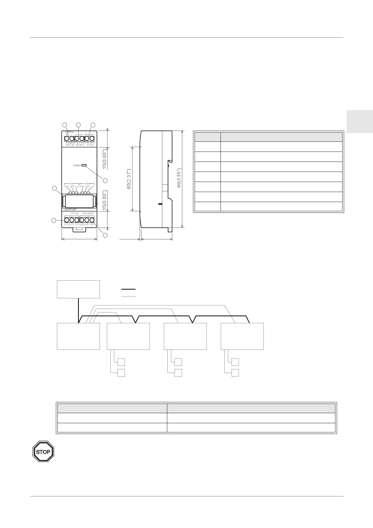
Figure 12.1:External Dimensions
Unit:mm (inches)
ENG
1
2
3
Table 12.1:
Item
Description
1
+24V DC Power Supply
2
Channel 1 Voltage Output Terminal
3
Channel 2 Voltage Output Terminal
4
Channel 1 PT100 Sensor Input Terminal
7
6
5
Channel 2 PT100 Sensor Input Terminal
6
Jumper pins for adjustment
7
Power LED
4
35.5(1.40")
5
1.5(0.06")
31.0(1.23")
12.2
System Configuration
Figure 12.2:
Power Supply
DC power line
24V DC
Analog signal
AL2-10MR-D
AL2-14MR-D
AL2-2PT-ADP
AL2-2PT-ADP
AL2-2PT-ADP
AL2-24MR-D
PT100
PT100
PT100
Sensor
Sensor
Sensor
For general specifications please refer to Chapter 2.
Table 12.2: Applicable Version
PLC Type
Applicable version
α2 Series (DC Version only)
V2.00 or later
VLS Software
V2.30 or later
Note
The AL2-2PT-ADP cannot be used with the original α Series Controllers.
ENG-61
AL2-2PT-ADP 12
12.3
Specification
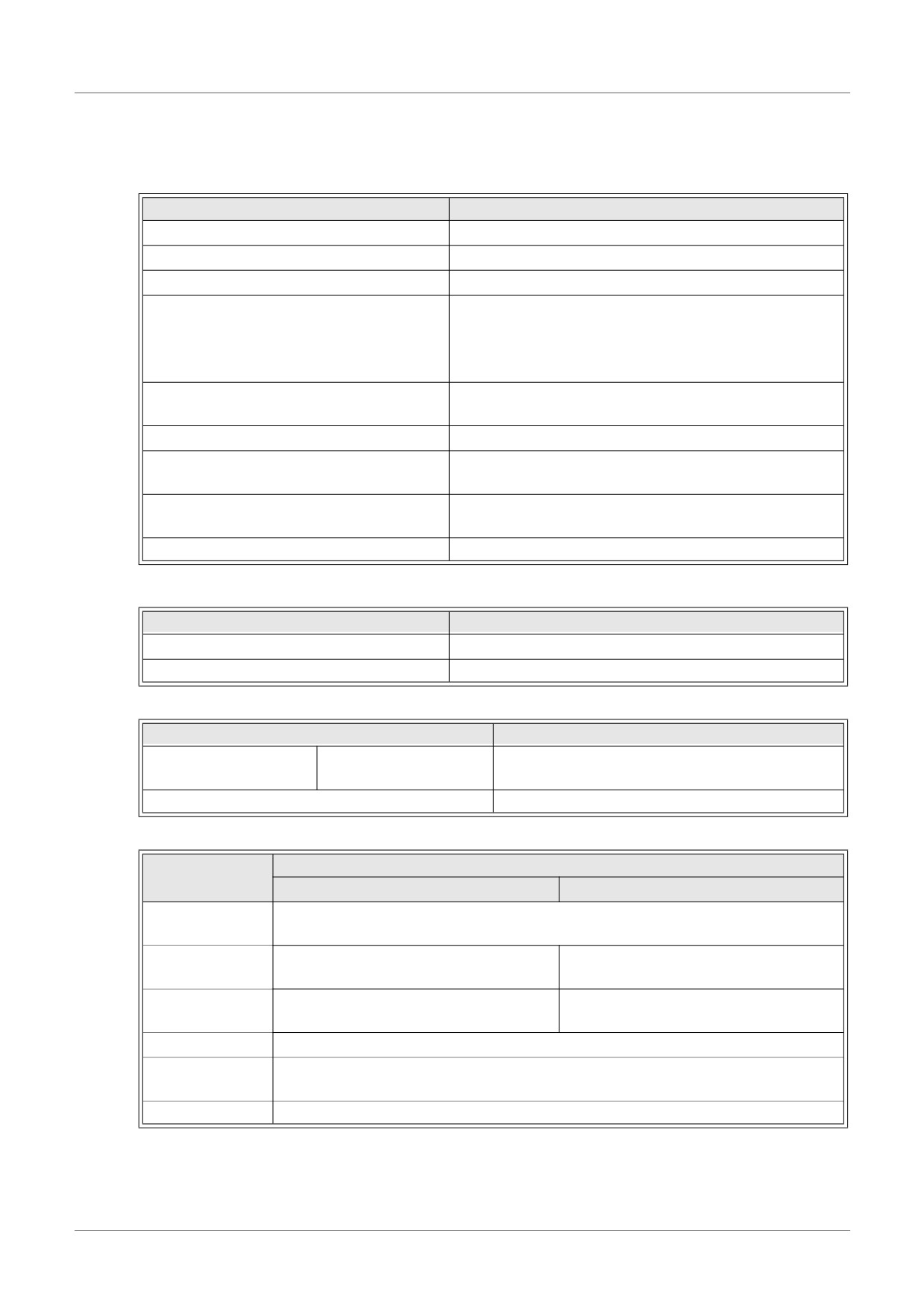
Table 12.3: General Specification
Item
Content
Operating Temperature
(-25) - 55°C / (-13) - 131°F
Storage Temperature
(-30) - 70°C / (-22) - 158°F
Humidity
35 - 85% Relative humidity, no condensation
Conforms to IEC 68-2-6; 10-57: Hz: 0.075mm
Constant Amplitude
Vibration Resistance - DIN Rail mounting
57-150Hz:9.8m/s2 Acceleration. Sweep Count for
X, Y, and Z: 10 times (80 minutes in each direction)
Conforms to IEC 68-2-27: 147m/s2 Acceleration, Action
Shock Resistance
Time: 11ms 3 times in each direction X, Y and Z
Noise Immunity
1000 Vpp, 1µs, 30-100Hz tested by a noise simulator
500V AC~>1min per EN60730-1 between all terminals
Dielectric Withstand Voltage
and the DIN43880 control box or equivalent.
7MΩ 500V DC EN60730-1 between all terminals and
Insulation Resistance
the DIN43880 distribution box or equivalent
Operation Ambience
To be free of corrosive gases
Table 12.4: Power Specification
Item
Content
Power Supply
24V DC +20%, -15%
Maximum Power Consumption
1.0W
Table 12.5: Adjustment Standard
Item
Content
EN61131-2: 2007
EC Directive
EMC
EN60730-1: 2011
Certification of UL/cUL
File number: E95239
Table 12.6: Hardware Specifications
Specification
Item
Centigrade (°C)
Fahrenheit (°F)
Input
Plantinum temperature PT100 sensors (100Ω), 3-wire,
Specification
Temperature coefficient: JIS C 1604-1997 (IEC 751)
Compensated
-50°C - 200°C
-58°F - 392°F
Range
±1.5% (range of all temperatures) and
±1.5% (range of all temperatures) and
Overall accuracy
±1.0% (at 25°C)
±1.0% (at 77°F)
Resolution
0.5°C
D/A Conversion
20.5ms
Time
Isolation Circuit
No isolation between channels (input/output) and power
ENG-62
AL2-2PT-ADP 12
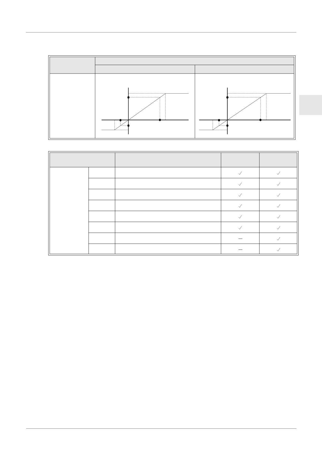
Table 12.6: Hardware Specifications
Specification
Item
Centigrade (°C)
Fahrenheit (°F)
Digital
Digital
+2075
+4055
+2000
+207.5°C
+3920
+405.5°F
Input
ENG
Characteristics
-50°C
-58°F
+200°C
Temperature
+392°F
Temperature
-500
-580
-57.5°C
(PT100)
-71.5°F
(PT100)
-575
-715
Table 12.7: Software Specification
AL2-14MR-D
Item
Content
AL2-10MR-D
AL2-24MR-D
M17
“ON” when there is a sensor defect at I01
M18
“ON” when there is a sensor defect at I02
M19
“ON” when there is a sensor defect at I03
M20
“ON” when there is a sensor defect at I04
System Bit
M21
“ON” when there is a sensor defect at I05
M22
“ON” when there is a sensor defect at I06
M23
“ON” when there is a sensor defect at I07
M24
“ON” when there is a sensor defect at I08
ENG-63
AL2-2PT-ADP 12
12.4
Wiring and Installation
12.4.1
Installation
Caution
• Do not install in areas with: excessive or conductive dust, corrosive or flammable gas,
moisture or rain, excessive heat, regular impact shocks or excessive vibration.
• The connectors must be covered to prevent contact with “Live” wires.
• The α2 Series Controller and AL2-2PT-ADP must be installed in a distribution box or a
control cabinet. The distribution box should be equipped with a cover for the AL2-2PT-
ADP module to avoid any possible foreign objects from falling inside.
• Leave a minimum of 10mm (0.40") of space for ventilation between the top and bottom
edges of the AL2-2PT-ADP and the enclosure walls.
• The maximum distance between the α2 Series Controller and the AL2-2PT-ADP should
be 3m (9’10”) or less.
• The power cable should be less than 10m in length.
• A sensor with insulation rated for 500V or more should be used when the sensor is
placed near a conductive material.
Figure 12.3: Installation
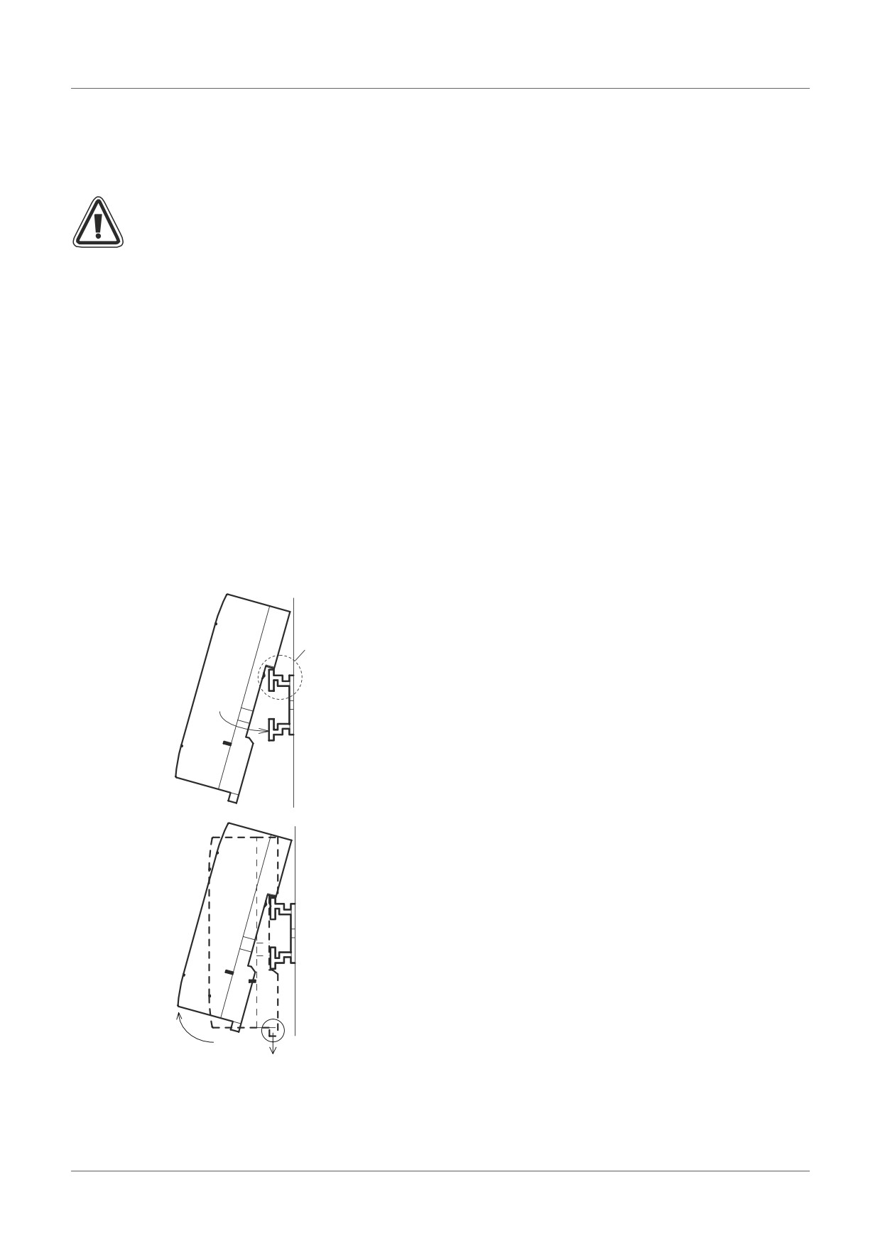
Attach
Units can be snap mounted to 35mm DIN rail (DIN
EN 50022). To release the unit pull the spring
loaded clips away from the rail and slide the unit off
(1)
and up.
1) To Attach
Align the upper side of the AL2-2PT-ADP DIN
rail mounting groove with the DIN rail (1) and
(2)
push it onto the rail (2).
2) To Release
Pull the DIN rail hook (1) and remove the AL2-
2PT-ADP.
Release
(2)
(1)
ENG-64
AL2-2PT-ADP 12
12.4.2
Wiring
Caution
• Please use an isolated Power supply and turn off the Power before any wiring operation
is performed.
• Input and Output cables should not be run through the same multi core cable or share
the same wire.
ENG
• Input cable (from sensor to AL2-2PT-ADP) must be less than 10m (32’81’’) and the
output cable length must be less than 3m (9'10").
• The wire should be used as a single cable or the multi core wires (can be used with a
crimp terminal) should be carefully twisted together.
Do not connect a soldered wire end to the AL2-2PT-ADP.
• To avoid damaging the wire, tighten to a torque of 0.5 - 0.6 N⋅m.
• The AL2-2PT-ADP should be adjusted for offset and gain purposes, therefore, turn off
the Power before performing the adjustment wiring.
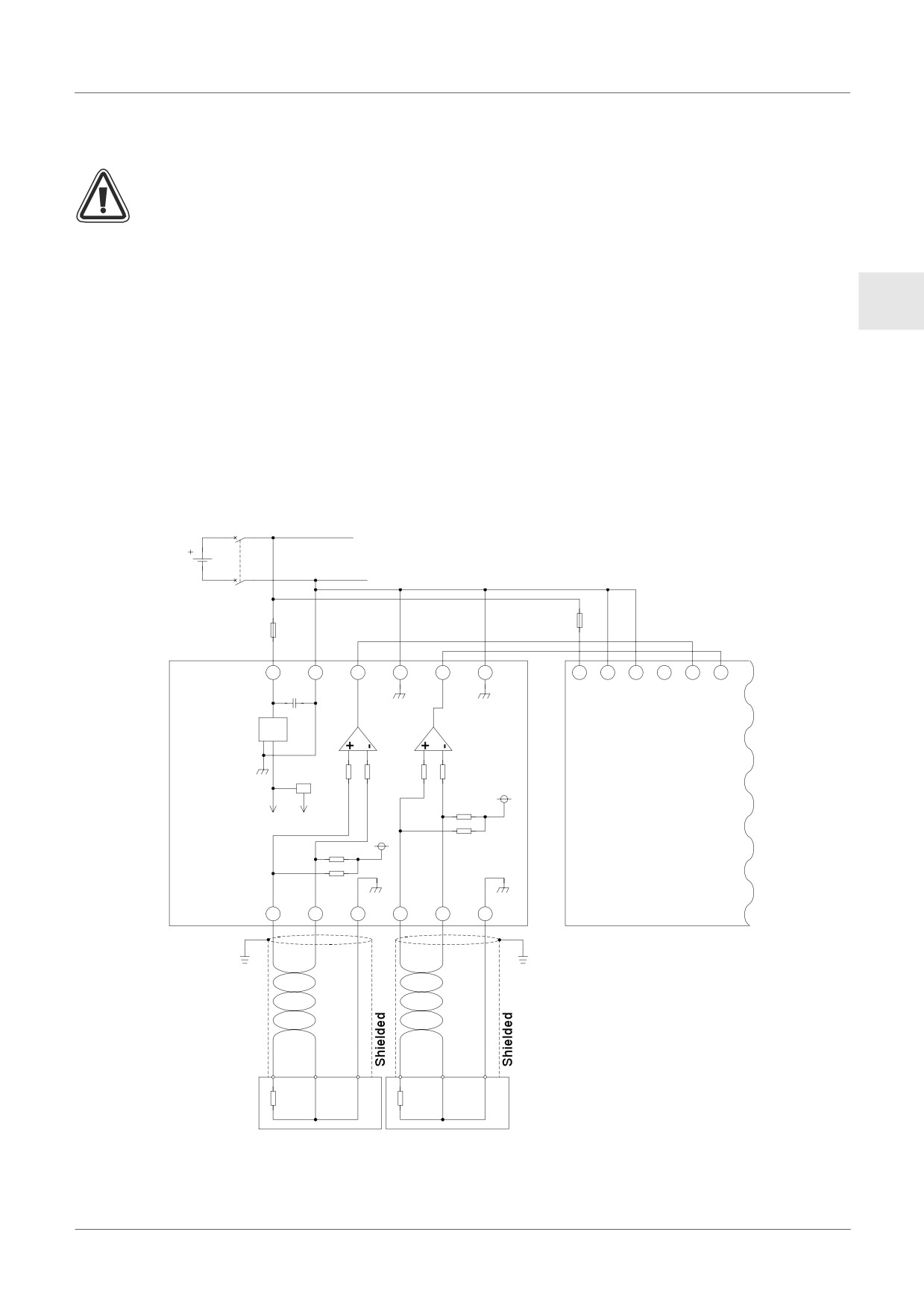
Figure 12.4:Wiring
24V
DC
1.0A
0.5A
24+
24-
V1+
V1-
V2+
V2-
+
-
(A)
(B)
1
2
100kΩ
100kΩ
100kΩ
100kΩ
5V
4.7kΩ
+15V 5V
5V
4.7kΩ
4.7kΩ
AL2-2PT-
4.7kΩ
AL2-10MR-D
ADP
AL2-14MR-D
L1+
L1-
I1-
L2+
L2-
I2-
AL2-24MR-D
Grounding
Grounding
resistance
resistance
100Ω or less
100Ω or less
PT100 Sensor
PT100 Sensor
ENG-65
AL2-2PT-ADP 12
12.4.3
Choosing a Temperature Scale
1) Turn on the power to the α2 controller and select “Others...” from the TopMenu.
TopMenu
C l o c kSe t
LANGUAGE
O t he r s . . .
2) Select “Analog In” from the Others... menu.
Ot her s . . .
Se r i a l Com
L i gh t T ime
Ana l og I n
3) Select “Temp. Scale” from the Analog In menu.
Ana l og I n
I
07
I
08
Temp . Sca l e
4) Choose “Celsius” or “Fahrenheit.” with the OK button
Ana l og I n
Temp . Sc a l e
Ce l s i u s
Fah r enhe i t
Only one system of units can be selected per controller.
The values under the Calibrate menu will remain in Celsius, regardless of the system
of units that is selected for the controller, as they are the labels for the jumper pins on
the Hardware.
ENG-66
AL2-2PT-ADP 12
12.4.4
Offset Adjustment
Note
If Gain adjustment is complete, then step 3 - 7 are not needed.
1) To begin the offset calibration for channel 1, turn off the power to the α2 controller and the
AL2-2PT-ADP, remove the temperature sensor and shorten the pins L1- and I1-.
ENG
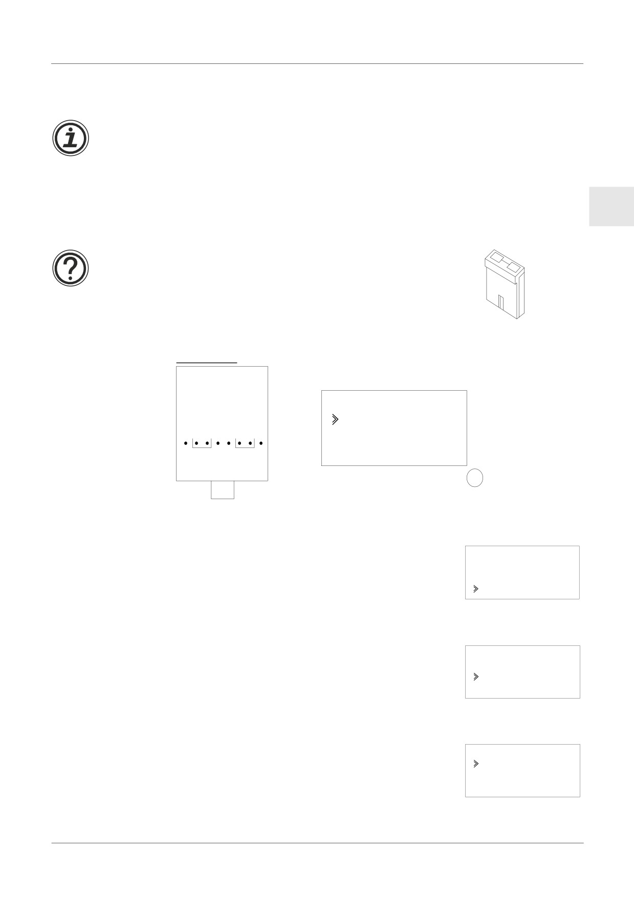
2) Remove the top cover from the jumper area and move the jumper to the pins labeled -50°C
as in “Hardware Setup” below. The external wiring should be performed as in the Hardware
Setup below.
TOP
Caution
The jumper should be installed correctly, otherwise, on occasion
electrical contact may not occur.
Bottom
Figure 12.5: AL2-2PT-ADP Offset Adjustment
Hardware Setup
Controller Setup
Ca l i brat e
-50°C
200°C
-50°C
-50°C
L1+ L1- I1-
OK
3) Turn the power on and select “Others...” from the TopMenu while in Stop Mode.
TopMenu
C l o c kSe t
LANGUAGE
O t he r s . . .
4) Select “Analog In” from the “Others...” menu.
Ot her s
L i gh t T i
me
Ana l og I
n
Pr ogCl ea r
5) Select the Input that is connected to the AL2-2PT-ADP module.
Ana l og
I n
I
01
I
02
I
03
ENG-67
AL2-2PT-ADP 12
6) Configure the input for temperature sensing with the AL2-2PT-ADP module by selecting
“Mode” and choosing “PT100” from the following screen.
I
01
I
01
Mode
No rma l
TC
PT100
7) After setting the mode to “PT100”, select “Calibrate” from the Analog input settings menu.
I
01
Mode
Ca l i b r a t e
O f f s e t f i ne
8) Select “-50°C” from the Calibrate menu as in “Controller Setup” in the figure 12.5 and press
OK. There should be a confirmation message that reads “OK.” If not, refer to the Applicable
Error Checks section below. This completes the offset calibration procedure. To calibrate
the offset for channel 2, repeat the steps above replacing L1-, L1+ and I1- with L2-, L2+ and
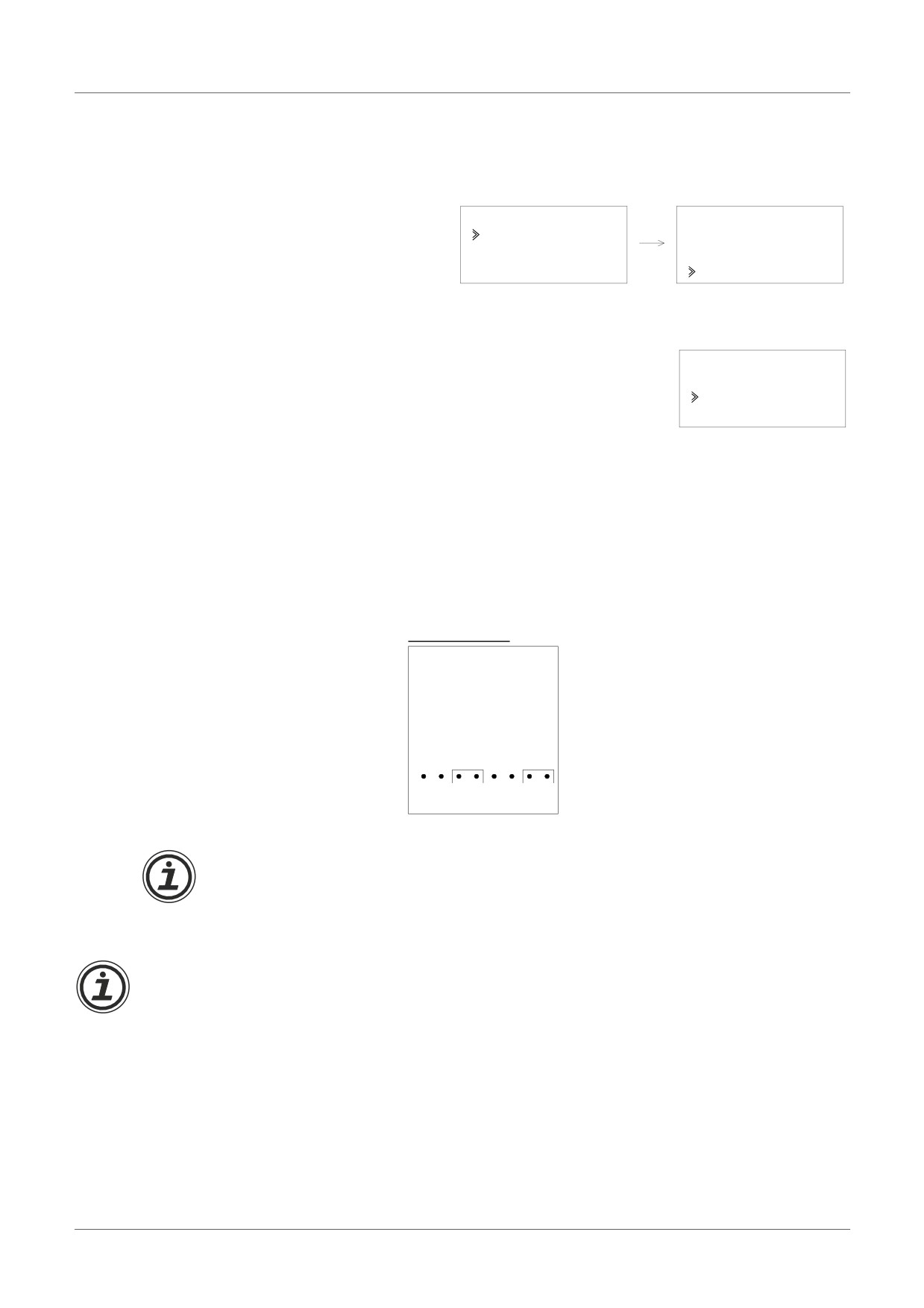
I2- respectively. When the calibration is finished, move the jumper to the “LINE” pins.
Figure 12.6: Jumper position after calibration
Hardware Setup
LINE
LINE
It is usually necessary to perform the Gain Adjustment when performing the Offset
Adjustment. See section 12.4.4 for more details.
12.4.5
Gain Adjustment
Note
If Offset adjustment is complete, then step 3 - 4 are not needed.
1) To begin the calibration for channel 1, turn off the power to the α2 controller and the AL2-
2PT-ADP, remove the temperature sensor and shorten the pins L1- and I1-.
ENG-68
AL2-2PT-ADP 12
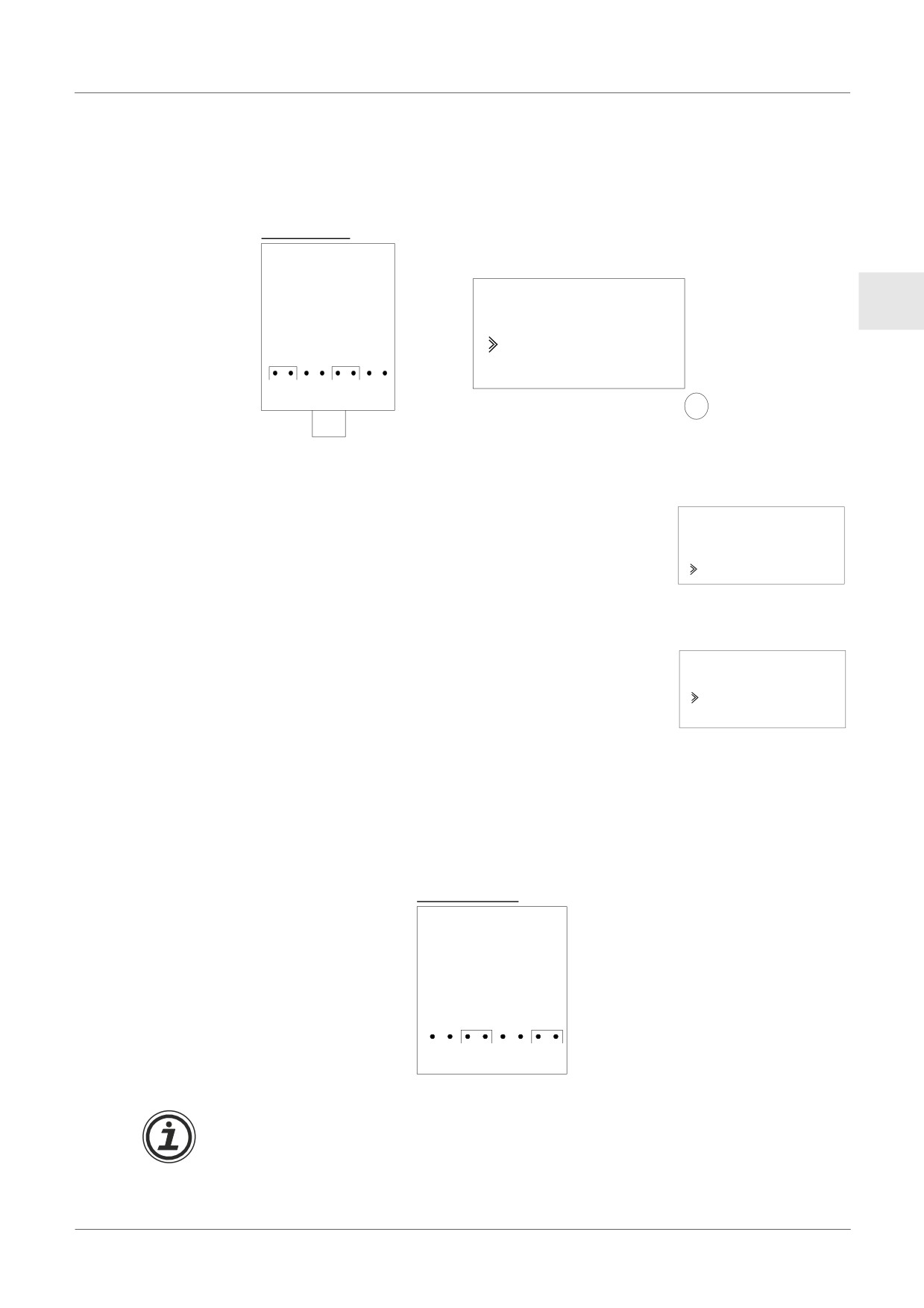
2) Remove the top cover from the jumper area and move the jumper to the pins labeled 200°C
as in “Hardware Setup” below.
Figure 12.7: AL2-2PT-ADP Gain Adjustment
Hardware Setup
Controller Setup
Ca l i brat e
ENG
-50°C
200°C
200°C
200°C
L1+ L1- I1-
OK
3) Turn the power on and select “Others...” from the TopMenu while in Stop Mode.
TopMenu
C l o c kSe t
LANGUAGE
O t he r s . . .
4) After setting the mode to “PT100” (See the Offset Adjustment description above.), select
“Calibrate” from the Analog input settings menu.
I
01
Mode
Ca l i b r a t e
O f f s e t f i ne
5) Select “200°C” from the Calibrate menu as in “Controller Setup” in the figure 12.7 and press
OK. There should be a confirmation message that reads “OK.” If not, refer to the Applicable
Error Checks section below. This completes the gain calibration procedure. To calibrate the
gain for channel 2, repeat the steps above but replace L1-, L1+ and I1- with L2-, L2+ and I2-
respectively. When the calibration is finished, move the jumper to the “LINE” pins.
Jumper position after calibration
Hardware Setup
LINE
LINE
It is usually necessary to perform the Offset Adjustment when performing the Gain
Adjustment. See section 12.4.3 for more details.
ENG-69
AL2-2PT-ADP 12
12.4.6
Fine Offset Adjust
The fine adjust should only be performed after both Gain and Offset Adjusts have
been performed.
1) From the TopMenu, select “Others...”
TopMenu
C l o c kSe t
LANGUAGE
O t he r s . . .
2) From the “Others...” menu, select “Analog In”
Ot her s
L i gh t T i
me
Ana l og I
n
Pr ogCl ea r
3) From the Analog In menu select an input that is configured for PT100 input.
Ana l og I n
I
01
I
02 : PT100
I
03 : TC
4) Select “Offset fine” from the Analog Input settings menu.
I
02
Mode
Ca l i b r a t e
Of f se t f i ne
5) Using the + and - buttons, enter a value from -15.5°C to 15.5°C (-27.9°F to 27.9°F).
Press the OK button when finished.
I
02
O f f s e t f i ne
0 .0 °C
ENG-70
AL2-2PT-ADP 12
12.4.7
Applicable Error checks
In the event that the input voltage is greater than 11 V or equal to 0V the following system flags
will be set.
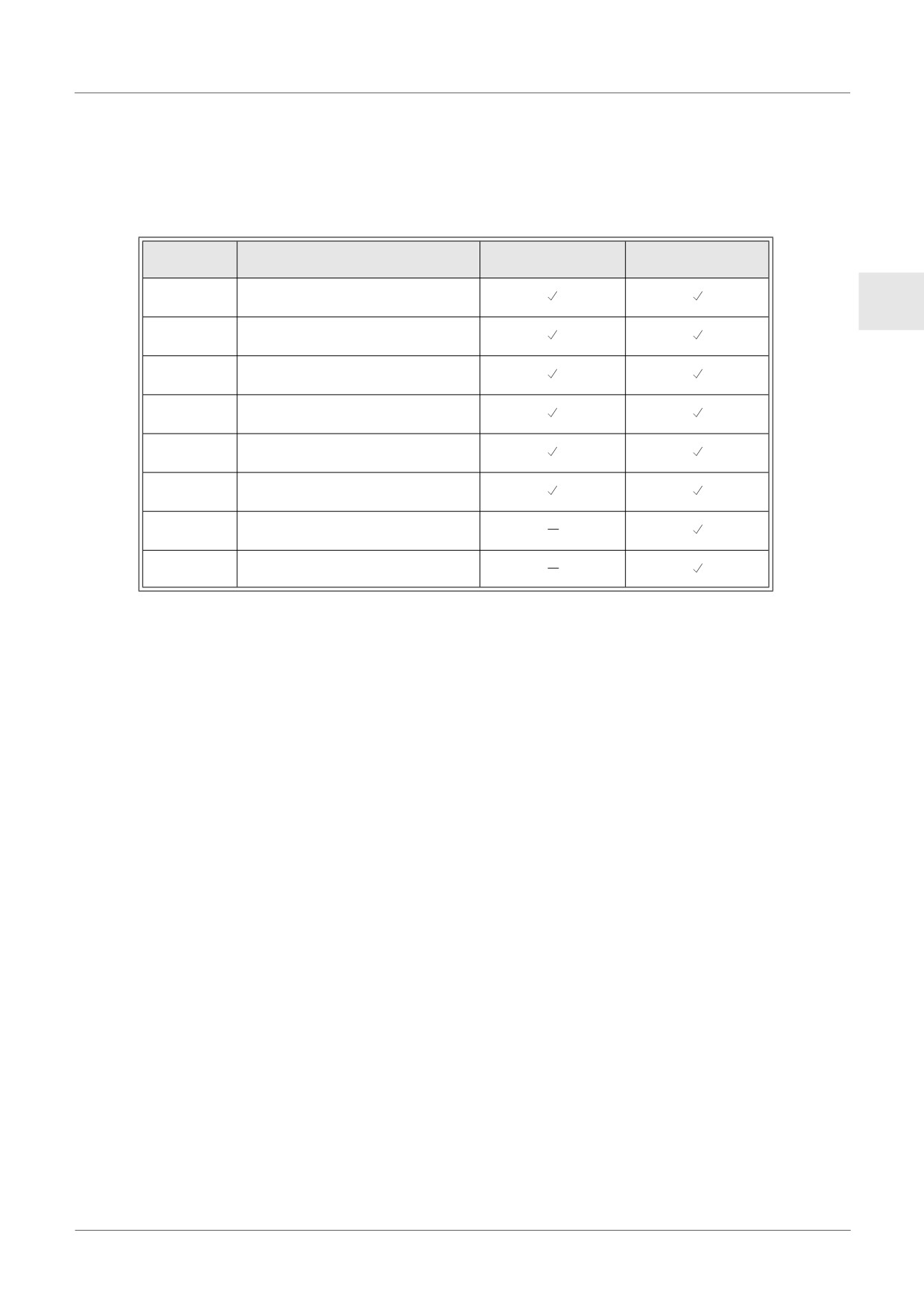
Table 12.8:
AL2-14MR-D
AL2-10MR-D
AL2-24MR-D
0: Normal
M17
1: Defect at I01
ENG
0: Normal
M18
1: Defect at I02
0: Normal
M19
1: Defect at I03
0: Normal
M20
1: Defect at I04
0: Normal
M21
1: Defect at I05
0: Normal
M22
1: Defect at I06
0: Normal
M23
1: Defect at I07
0: Normal
M24
1: Defect at I08
- If the flags in the table above are activated, check that:
• a sensor is connected
• there is not a break in the sensor connection
• the temperature is not greater than the specified limit
• that power is being supplied to the AL2-2PT-ADP.
- If the “Error” message appears instead of “OK” while offset/gain calibration, check that.
• The power is being supplied to the AL2-2PT-ADP.
• The AL2-2PT-ADP is connected to α2 correctly.
• The input, which connects the AL2-2PT-ADP is selected for calibration.
• The AL2-2PT-ADP inputs L1- and l1- are shortened.
• The jumper on is placed either on the “-50°C” position or the “200°C” position.
• The calibration menu entry related to the jumper position is selected (“-50°C” or “200°C”).
ENG-71